Article

A Grain Boundary Regulates the Friction Behaviors between Graphene and a Gold Substrate

1
The Institute of Technological Sciences, Wuhan University, Wuhan 430072, China
2
School of Power and Mechanical Engineering, Wuhan University, Wuhan 430072, China
3
Nuclear Engineering and Radiological Sciences, University of Michigan, Ann Arbor, MI 48109, USA
*
Authors to whom correspondence should be addressed.
Submission received: 27 June 2019 / Revised: 28 July 2019 / Accepted: 9 August 2019 / Published: 13 August 2019
(This article belongs to the Special Issue Graphene Mechanics)

Abstract

:
The nanofriction of graphene is critical for its broad applications as a lubricant and in flexible electronics. Herein, using a Au substrate as an example, we have investigated the effect of the grain boundary on the nanofriction of graphene by means of molecular dynamics simulations. We have systematically examined the coupling effects of the grain boundary with different mechanical pressures, velocities, temperatures, contact areas, and relative rotation angles on nanofriction. It is revealed that grain boundaries could reduce the friction between graphene and the gold substrate with a small deformation of the latter. Large lateral forces were observed under severe deformation around the grain boundary. The fluctuation of lateral forces was bigger on surfaces with grain boundaries than that on single-crystal surfaces. Friction forces induced by the armchair grain boundaries was smaller than those by the zigzag grain boundaries.

1. Introduction

Graphene, a single sheet of graphite, possesses exceptional mechanical properties [1,2], large transparency [3], extraordinary electronic mobility [4], and adaptable electronic properties [5] owing to its unique two-dimensional structure [6,7,8,9,10]. It is a promising material in the field of nanoscale electronics [11,12,13,14]. However, the properties of these nanoscale electronics can be affected by the friction behaviors of graphene [15]. A number of studies have been conducted to investigate the friction mechanism of graphene [16,17,18,19]. Atomic force microscopy (AFM) has been widely applied to measure the friction force between the scanning probe tip and the graphene [20,21,22,23,24]. The results show that graphene has atypical friction behaviors. For instance, the nanoscale friction increases and then decreases with increasing load [23]. A negative friction coefficient was found on chemically modified graphite [20]. The friction of either monolayer or bilayer graphene is inversely proportional to the strain in graphene, which violates Amontons’ law [25]. Besides, lubricating behaviors of graphene have also been examined. The superlubricity, a regime of motion in which friction nearly vanishes, was found between graphene nanoribbons and gold surfaces [26,27], suggesting that graphene is a promising lubricant [28,29,30]. The friction on a sliding steel surface was found to be reduced by the solution-processed graphene layer [31]. The friction of graphene can be modulated using nitrogen-doping [32], surface wrinkles [33,34], oxidation [35,36], hydrogenation [24], and fluorination [37]. Furthermore, frictional properties of few-layer graphene under the effect of elastic deformation have been studied. The results revealed that the observed friction force is directly related to the effects of surface compliance [38]. The friction of graphene is found to be attributable to the interaction between the incommensurate interface lattices [39]. The effect of temperature has been explored [40,41]. The friction forces between Si tips and a supported graphene increase with rising temperature [41], while the friction forces between carbon nanotubes and graphene are found to either increase or decrease locally depending on the detection parameters [40].
Among previous studies, the friction behaviors between graphene and single-crystal gold have been investigated [42] in relation to the wide usage of gold in graphene-based devices [43,44,45]. The contact of the gold and the graphene in these devices emphasizes the great importance of the friction behaviors between them. In applications, defects in materials, especially grain boundaries, are common. Grain boundaries have a greater influence on the friction behaviors than what point defects and line defects may do because of the interaction with another type of contact surface as well as the deformation around grain boundaries. Therefore, the investigation of the effects of grain boundaries on the friction behavior has a greater practical value for the design of the nanoscale electronic devices. The effect of the grain boundary on the friction behaviors of 2D materials has not been systematically studied. The results may be also applicable to other metal substrates. In this study, we used molecular dynamics (MD) simulations to investigate the friction behaviors between the graphene flake and gold substrate with and without a grain boundary. The effects of various factors on friction behaviors regulated by a grain boundary were investigated.

2. Materials and Methods

The MD simulations were performed using the Large-scale Atomic/Molecular Massively Parallel Simulator (LAMMPS, distributed by Sandia National Laboratories) [46]. MD is a reliable and indispensable tool in various investigations [47]. The MD model for this study is shown in Figure 1. It consisted of a graphene flake dyed blue and a gold substrate dyed cyan. A 90° <010> grain boundary was in the middle of the system, represented by the blue translucent rectangle. We built the grain boundary with two single crystals. For the first crystal on the left part, the coordinate system was set as x—[110], y—[001], and z—[1 1 ( ) 0]. For the second crystal on the right part, the coordinate system was set as x—[100], y—[011], and z—[0 1 ( ) 1]. The whole system was 20 nm × 15 nm × 3 nm in size, which contained 53309 Au atoms and 1372 C atoms. Three layers of atoms at the bottom of the substrate were taken as boundary atoms and fixed in space. Simulations were conducted with the graphene atoms constrained in the y-direction to maintain the orientation of the flake. The graphene flake was dragged by a harmonic spring to slide on the gold substrate. The spring was tied to a virtual atom that had a constant velocity. The stiffness of the spring was 10 N/m [48], which was used to represent the compliance of an AFM system. An equal pulling force was applied to every atom of the flake. The lateral force was obtained as in the AFM experiment. AFM is an advanced tool to investigate the friction behaviors of the target material due to the interaction between its tip and the surface of the material [19,20,49]. In our simulations, the graphene flake served as the tip. In our case, the puckering effect [49] did not exist. The contact area between the tip and the surface had a slight change under various detection parameters. A constant normal pressure was applied to the graphene atoms. The boundary conditions were periodic in the x- and y-directions, and fixed in the z-direction. We examined the friction behaviors between graphene and the gold substrate under different pressures, velocities, temperatures, contact areas, and relative rotation angles. In order to obtain adequate data for statistical analysis, for each condition we performed simulations several times with different initial positions of the graphene flake. The average friction forces under each condition, as well as the uncertainties, are shown in Appendix A. The uncertainties are the standard deviations of the corresponding data.
The interaction between Au atoms was described using an embedded atom method (EAM) potential [50]. The interaction among C atoms was modeled using the modified adaptive intermolecular reactive empirical bond order (AIREBO) potential [51,52]. The AIREBO potential is adequate for describing the hydrocarbon bonds and the van der Waals forces. The interaction between the Au atoms and C atoms was modeled using the Lennard-Jones (LJ) potential. The parameters were: ε = 22.0 meV and σ = 2.74 Å [53,54]. For the purpose of controlling the temperature of the system, time integration on Nose-Hoover style non-Hamiltonian equations of motion, which are designed to generate positions and velocities sampled from the canonical ensemble (NVT), was performed [55].
Here, the flake was a 5.9 nm × 5.9 nm square in all simulations except in Section 3.4 and Section 3.5. The flake was placed above the substrate and fully relaxed before the pulling force and the normal pressure were applied. The ratio of the contact areas between the graphene and two single-crystal surfaces ranged from 0.59 to 1.70, except in Section 3.4. If not specified, the y-axis was along the armchair direction of the graphene and the simulations were conducted at 300 K with a pressure of 3.57 GPa. The default sliding velocity was 10 m/s.

3. Results and Discussion

It has been found that the nanofriction of single-crystal surfaces is related to many factors such as mechanical pressures and velocities. Compared with single-crystal materials, the polycrystalline material is more common in the real applications. The grain boundary can regulate friction behaviors between graphene and gold substrate and modify the influence of these factors on nanofriction. Therefore, it is vital to study the coupling effects of the grain boundary with mechanical pressures [56], velocities [57,58], temperatures [41], contact areas, and relative rotation angles [42] on nanofriction.

3.1. Mechanical Pressure Effect

Three pressures—1.19 GPa, 2.38 GPa, and 3.57 GPa—were applied. The effect with a larger pressure, such as 6 GPa, was beyond the scope of our study because under this condition, the graphene flake was squeezed into the grain boundary. Besides, our uniaxial compression simulations showed that the Au substrate can sustain elastic pressure as large as 5.1 GPa. This might be the reason why there is no plastic deformation of the gold substrate under these pressures. Figure 2 illustrates the lateral force as a function of the sliding distance of the harmonic spring with various pressures. The lateral forces on the single-crystal surfaces from the current study align with the results of previous research [42]. On the two single-crystal surfaces, the lateral forces increased linearly, and then suddenly dropped and repeated periodically. These repetitive behaviors are called stick-slip motions. In these curves, a maximum lateral force represents a maximum offset of the graphene flake from the equilibrium position. Every drop of the lateral force represents a jump of the tip from a stable equilibrium position on the surface into the neighboring one. When the tip jumps across the equilibrium position of the spring, the lateral force becomes negative.
The stick-slip motions were also observed from the lateral forces on the boundary surface, as shown in Figure 2. The periods of these curves varied with the movement because of the grain boundary. The periods of the lateral forces and the maximum offsets on the boundary surface sometimes coincided with those on the two single-crystal surfaces. This behavior of the lateral forces on the boundary surface can be explained using the Frenkel–Kontorova model. In this model, the friction behaviors strongly depend on the ratio of the two lattice spacings of the contact surfaces. When they are commensurate, the atoms of graphene flakes are spatially matched with the atoms of the substrate. In this case, the contribution of each atom pair to the lateral force is maximized, which leads to a high lateral force. As shown in Figure 1, the lattice spacings of two single-crystal surfaces were different: 2.8 Å for the first surface and 4.08 Å for the second surface. The atoms of graphene only matched well with the atoms of one surface. The interactions of each atom pair could not reach their peaks simultaneously. The result was that the maximum offsets on the boundary surfaces were sometimes smaller than those on the single-crystal surfaces along the movement. Smaller maximum offsets resulted in smaller friction forces. For both pressures of 1.19 GPa and 2.38 GPa, the friction forces on the boundary surface were only 60% of those on the single crystal surfaces. Our finding agrees with the experimental observations in Tripathi et al. [59], who found that the friction forces between a silica tip and few-layer graphene over Ni interface boundaries are smaller than those between a silica tip and few-layer graphene over Ni grain.
The average maximum offset on different surfaces with different pressures are shown in Figure 3a. It can be seen that the larger the pressures, the larger the maximum offsets if other parameters remained unchanged. For the single-crystal surfaces, with a 1.19 GPa increment in pressure, the maximum offsets increased by approximately 0.6 Å. Different from the single-crystal surfaces, the boundary surface with different pressures was deformed to different degrees, as shown in Figure 3b and Figure S1 in Supplementary Materials. When the pressure increased from 1.19 GPa to 2.38 GPa, the deformation was not greatly intensified. However, when the pressure increased to 3.57 GPa, the deformation was much bigger than that with a 2.38 GPa pressure. This deformation led to a more rapid increase in the average maximum offset compared to the increase on the smooth surfaces of the single crystal. Despite the severe deformation, the friction force on the boundary surface was still smaller than those on the single-crystal surface. Further simulations revealed that the deformations of the grain boundary under these pressures were reversible. The friction coefficient, which was generally independent of the pressure, varied with the pressures on the boundary surface. This was because the pressures induced a different corrugation of the graphene and changed the friction coefficient. The relation between the friction force and pressure was not linear on the boundary surface.

3.2. Velocity Effect

The influence of velocity on the boundary effect was explored. The velocities were set as 5 m/s, 10 m/s, and 20 m/s. Figure 4a–c shows the lateral force as a function of sliding distance with various velocities. It was demonstrated that on the single-crystal surfaces, the maximum offsets and periods of the lateral forces were almost the same with different velocities, indicating that the velocity had little influence on the friction behaviors on the single-crystal surfaces. This finding agrees with those of previous studies. In the continuous regime, the friction was constant with increasing velocity [60]. The velocities used in our study were above the velocities accessible by AFM experiments. Therefore, the frictions were expected to be constant.
However, velocity played an important role in the deformation of the graphene. Figure 4d shows the deformation of graphene at different velocities. The deformation at 10 m/s was larger than those at other velocities. A possible explanation for the greater deformation at 10 m/s could be that at a lower velocity of 5 m/s, there was more time for the graphene flake to relax and avoid strong interaction with the grain boundary; at a higher velocity of 20 m/s, the flake rushed across the grain boundary and caused smaller deformation. The difference of the deformation could have an effect on the friction behaviors. For the friction force on the boundary surface, there was little difference with various velocities. This was because the difference of the deformation was not large enough to induce an obvious difference in the friction force. However, different deformation caused strong fluctuations of the maximum offset when the velocity varied, as shown in Figure 4b. The maximum offsets fluctuated, probably because the interaction potential on the boundary surface was not periodic around the grain boundary.

3.3. Temperature Effect

Given that the graphene-based devices may be required to operate under different temperatures, we have conducted the simulations at 100 K, 200 K, and 300 K to study the effect of temperature. The results are shown in Figure 5. The friction forces on the single crystal surfaces were nearly unaffected by different temperatures, while the friction forces on the boundary surface varied with temperature. In previous research, the friction forces between the Si tip and the supported graphene decreased with the temperature under a scan velocity of 1 m/s [40]. The discrepancy might be attributed to the grain boundary and high velocity (10 m/s) used in this study. Our recent study of polycrystalline graphene showed that the surface corrugation increases with an increase in temperature [61]. An increase in surface corrugation led to an increase of friction forces. In addition, with a high velocity, there was less time for the interacting atoms to relax and avoid strong interaction, which weakened the effect of the rising temperature.
The influence of temperature on friction behavior with the grain boundary could be a result of a combination of disorder and deformation. On the one hand, the increase of temperature boosted the degree of disorder near the grain boundary, which disrupted the stick-slip motions and reduced the friction force. On the other hand, the deformation of the substrate depended on the temperature. Theoretically, a higher temperature leads to larger deformation of the material, which could magnify the friction force. Therefore, the friction force on the boundary surface at 300 K was larger than those at the other two temperatures.

3.4. Effect of the Ratio of Contact Areas

This study has also examined the ratio of the contact areas between the graphene and the two single-crystal surfaces. Owing to the exceptional properties of this two-dimensional material, it is necessary to explore the influence of the ratio of two contact areas. In Figure 6a, a triangular flake consisting of 1225 atoms was pulled across the grain boundary. The normal pressure was 4.00 GPa, which meant the atoms in the triangle flake bore 12% more pressure than those in the square flake. The position where we started to record the lateral force is shown in Figure 6a. It can be observed in Figure 6b that the lateral force on the second surface was much bigger than that on the first surface. At the beginning, the maximum offset and the period of the lateral force on the boundary surface were closer to those on the first surface because the lateral force mainly came from the interaction between the graphene and the first surface. The contact area between the flake and the second surface increased when the flake moved forward, which led to a slow increase of the lateral force, as shown in Figure 6b. The period of the stick-slip motions on the first and second single-crystal surfaces were 3 Å and 7 Å, respectively. It can be seen in Figure 6b that the periods of the stick-slip motions were unsteady. A possible cause for the unsteady period is the increasing contact length between the graphene and the grain boundary. The longer contact length caused a greater interference in the period.

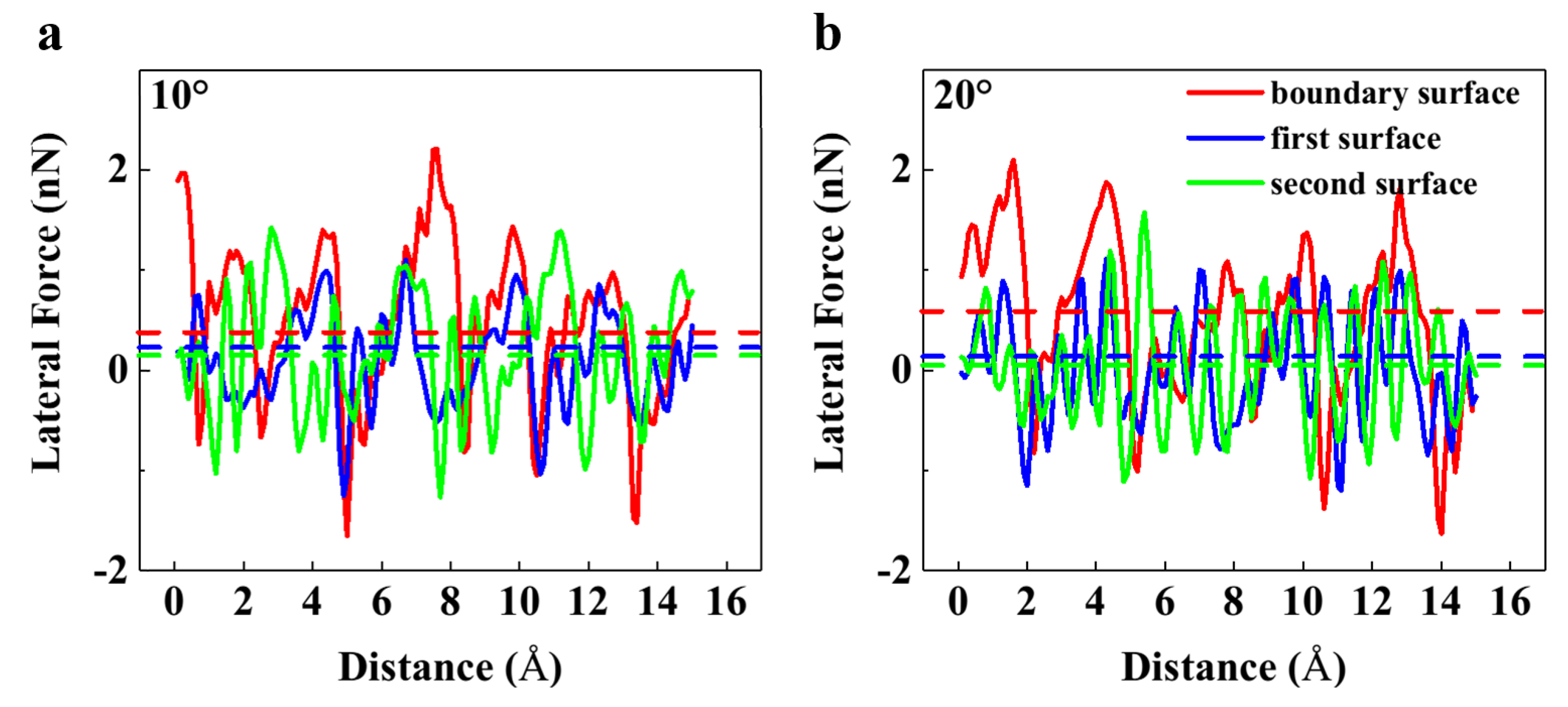
3.5. Relative Rotation Angle

We explored the friction behaviors at four relative rotation angles. First, we dragged the graphene flake in the zigzag direction of graphene along the x-axis. Then, we rotated the flake by 30°, which put in the armchair direction of graphene along the x-axis. The flake was rounded to make sure the differences of the friction behaviors were only caused by from the relative rotation angles. The rounded flake had a radius of 3.31 nm, consisting of 1356 atoms.
As shown in Figure 7a, the stick-slip motions vanished on the first surface. The lateral force on the first surface fluctuated around zero and the lateral force on the boundary surface was between those on the two single-crystal surfaces. The maximum offset on the second surface was 9.0 Å. In contrast, the maximum offset on the boundary surface fluctuated between 3 Å and 5 Å. This discrepancy indicated that the lateral force on the boundary surface could be the average of those on the two single-crystal surfaces. In Figure 7b, the lateral forces on both single crystal surfaces lingered around zero, while the lateral force on the boundary surface was much bigger. This could be attributed to the deformation of the substrate, which directly magnified the lateral force. The friction force on the boundary surface was smaller than that in the armchair direction situation. The friction force on the boundary surface in the armchair direction situation was 1.80 nN, which was a combination of the friction force on the second surface and the interaction between the graphene and the grain boundary. The friction force on the boundary surface in the zigzag direction situation was 0.96 nN, most of which came from the interaction between the graphene and the grain boundary. Therefore, the interaction in the armchair direction along the x-axis was smaller than that in the zigzag direction along the x-axis.
The situations at other relative rotation angles were also investigated. Considering the hexagonal symmetry structure of the unit cell of graphene, we rotated the rounded flake to change the angle between its zigzag direction and the x-axis to 10° and 20°. The results are shown in Figure 8. Superlubricity could be observed on the two single-crystal surfaces for both cases. Their friction forces on the boundary surface were 0.38 nN and 0.69 nN, respectively. The friction forces on the single crystal surfaces with the angle of 10° were slightly larger than those with the angle of 20°. As a result, we found that with the angle of 20°, the interaction between the graphene and the grain boundary was greater. Compared to the situation when the angle was 0°, as shown in Figure 7b, there were extremely low friction forces on the single-crystal surfaces in all three situations. The friction force on the boundary surface with the zigzag direction along the x-axis was 1.09 nN, as shown in Table A5, while the friction force on the single crystal surfaces were 0.42 nN and 0.09 nN, respectively. Considering the relation between the contact area and lateral force revealed in Section 3.4, the interaction with the grain boundary induced a friction force of about 0.8 nN, which was larger than those in other situations.

4. Conclusions

We have investigated the effects of grain boundaries on the friction behaviors between graphene and a gold substrate utilizing MD simulations. The friction behaviors were systematically examined with different mechanical pressures, velocities, temperatures, contact areas, and relative rotation angles. The results show that in the low-pressure situation, the grain boundary reduced the friction force due to the incommensurate atom spacings of the two single crystal surfaces. Under different velocities and temperatures, the friction behaviors on the boundary surface differed from those on the single-crystal surfaces owing to the deformation and disorder of the grain boundary. Furthermore, the ratio of the contact areas between graphene and the two single-crystal surfaces had a strong effect on the friction behaviors on the boundary surface. The larger the contact area, the greater the contribution to the lateral force. Finally, the interaction between the graphene and the grain boundary was strongly affected by the relative rotation angle. The friction force induced by the grain boundary was smaller in the armchair direction of the graphene perpendicular to the grain boundary than that in the zigzag direction. The friction force induced by the grain boundary was larger when the zigzag direction was 20° from the x-axis than for 10°. These findings revealed the effect of a grain boundary in regulating the friction behaviors of graphene, and therefore could be beneficial to the fabrication of nanoscale graphene-based devices.

Supplementary Materials

The following are available online at https://0-www-mdpi-com.brum.beds.ac.uk/2073-4352/9/8/418/s1, Figure S1: The images of the deformed samples with different pressures of (a) 1.19 GPa, (b) 2.38 GPa, and (c) 3.57 GPa.

Author Contributions

P.H., Q.C., and Q.P. conceived the idea of the paper and wrote the paper; P.H. conceived, designed, and performed the simulations; P.W., H.W., S.Z., S.L. (Shuting Lei), and S.L. (Sheng Liu) offered much helpful advice. All the authors had a full discussion and commented on the paper.

Funding

This research was funded by the National Natural Science Foundation of China (No. 51727901).

Acknowledgments

We acknowledge the calculation support from the Supercomputing Center of Wuhan University.

Conflicts of Interest

The authors declare no conflict of interest.

Appendix A

Table A1. The average maximum offsets with different pressures.
Pressure (GPa)Boundary Surface (Å)First Surface (Å)Second Surface (Å)
1.192.5 ± 0.52.7 ± 0.23.4 ± 0.2
2.383.4 ± 0.63.1 ± 0.34.1 ± 0.3
3.574.7 ± 0.73.7 ± 0.45.0 ± 0.3
Table A2. The friction forces under different pressures.
Pressure (GPa)Boundary Surface (nN)First Surface (nN)Second Surface (nN)
1.190.61 ± 0.071.16 ± 0.131.29 ± 0.03
2.381.10 ± 0.151.75 ± 0.171.95 ± 0.07
3.571.84 ± 0.312.24 ± 0.312.69 ± 0.07
Table A3. The friction forces with different velocities.
Velocity (m/s)Boundary Surface (nN)First Surface (nN)Second Surface (nN)
51.90 ± 0.302.18 ± 0.242.57 ± 0.06
101.84 ± 0.312.24 ± 0.312.69 ± 0.07
201.91 ± 0.222.08 ± 0.262.49 ± 0.09
Table A4. The friction forces at different temperatures.
Temperature (K)Boundary Surface (nN)First Surface (nN)Second Surface (nN)
1001.56 ± 0.142.18 ± 0.222.65 ± 0.12
2001.73 ± 0.292.28 ± 0.252.65 ± 0.12
3001.84 ± 0.312.24 ± 0.312.69 ± 0.07
Table A5. The friction forces at different relative rotation angles.
Rotation AngleBoundary Surface (nN)First Surface (nN)Second Surface (nN)
Zigzag direction1.09 ± 0.280.42 ± 0.310.09 ± 0.02
10°0.38 ± 0.200.24 ± 0.160.15 ± 0.03
20°0.59 ± 0.160.14 ± 0.110.05 ± 0.01
Armchair direction1.80 ± 0.380.05 ± 0.053.40 ± 0.51

References

  1. Wang, P.; Cao, Q.; Yan, Y.; Nie, Y.; Liu, S.; Peng, Q. Graphene surface reinforcement of iron. Nanomaterials 2019, 9, 59. [Google Scholar] [CrossRef] [PubMed]
  2. Wang, H.; Cao, Q.; Peng, Q.; Liu, S. Atomistic study of mechanical behaviors of carbon honeycombs. Nanomaterials 2019, 9, 109. [Google Scholar] [CrossRef] [PubMed]
  3. Nair, R.R.; Blake, P.; Grigorenko, A.N.; Novoselov, K.S.; Booth, T.J.; Stauber, T.; Peres, N.M.R.; Geim, A.K. Fine structure constant defines visual transparency of graphene. Science 2008, 320, 1308. [Google Scholar] [CrossRef] [PubMed]
  4. Pallecchi, E.; Lafont, F.; Cavaliere, V.; Schopfer, F.; Mailly, D.; Poirier, W.; Ouerghi, A. High electron mobility in epitaxial graphene on 4H-SiC(0001) via post-growth annealing under hydrogen. Sci. Rep. 2014, 4, 4558. [Google Scholar] [CrossRef] [PubMed]
  5. Pereira, V.M.; Castro Neto, A.H. Strain engineering of graphene’s electronic structure. Phys. Rev. Lett. 2009, 103, 046801. [Google Scholar] [CrossRef] [PubMed]
  6. Koenig, S.P.; Boddeti, N.G.; Dunn, M.L.; Bunch, J.S. Ultrastrong adhesion of graphene membranes. Nat. Nanotechnol. 2011, 6, 543–546. [Google Scholar] [CrossRef] [PubMed]
  7. Zheng, S.; Cao, Q.; Liu, S.; Peng, Q. Atomic structure and mechanical properties of twisted bilayer graphene. J. Compos. Sci. 2018, 3, 2. [Google Scholar] [CrossRef]
  8. Cao, Q.; Geng, X.; Wang, H.; Wang, P.; Liu, A.; Lan, Y.; Peng, Q. A review of current development of graphene mechanics. Crystals 2018, 8, 357. [Google Scholar] [CrossRef]
  9. Lee, C.; Wei, X.D.; Kysar, J.W.; Hone, J. Measurement of the elastic properties and intrinsic strength of monolayer graphene. Science 2008, 321, 385–388. [Google Scholar] [CrossRef]
  10. Lei, S.; Cao, Q.; Geng, X.; Yang, Y.; Liu, S.; Peng, Q. The mechanical properties of defective graphyne. Crystals 2018, 8, 465. [Google Scholar] [CrossRef]
  11. Liu, M.; Yin, X.; Ulin-Avila, E.; Geng, B.; Zentgraf, T.; Ju, L.; Wang, F.; Zhang, X. A graphene-based broadband optical modulator. Nature 2011, 474, 64–67. [Google Scholar] [CrossRef] [PubMed]
  12. Traversi, F.; Raillon, C.; Benameur, S.M.; Liu, K.; Khlybov, S.; Tosun, M.; Krasnozhon, D.; Kis, A.; Radenovic, A. Detecting the translocation of DNA through a nanopore using graphene nanoribbons. Nat. Nanotechnol. 2013, 8, 939–945. [Google Scholar] [CrossRef] [PubMed]
  13. Margine, E.R.; Bocquet, M.L.; Blase, X. Thermal stability of graphene and nanotube covalent functionalization. Nano Lett. 2008, 8, 3315–3319. [Google Scholar] [CrossRef] [PubMed]
  14. Su, Y.; Kravets, V.G.; Wong, S.L.; Waters, J.; Geim, A.K.; Nair, R.R. Impermeable barrier films and protective coatings based on reduced graphene oxide. Nat. Commun. 2014, 5, 4843. [Google Scholar] [CrossRef] [PubMed]
  15. Kim, S.H.; Asay, D.B.; Dugger, M.T. Nanotribology and MEMS. Nano Today 2007, 2, 22–29. [Google Scholar] [CrossRef]
  16. Wang, W.; Peng, Q.; Dai, Y.; Qian, Z.; Liu, S. Distinctive nanofriction of graphene coated copper foil. Comput. Mater. Sci. 2016, 117, 406–411. [Google Scholar] [CrossRef]
  17. Liu, Y.; Grey, F.; Zheng, Q. The high-speed sliding friction of graphene and novel routes to persistent superlubricity. Sci Rep. 2014, 4, 4875. [Google Scholar] [CrossRef] [Green Version]
  18. Lodge, M.S.; Tang, C.; Blue, B.T.; Hubbard, W.A.; Martini, A.; Dawson, B.D.; Ishigami, M. Lubricity of gold nanocrystals on graphene measured using quartz crystal microbalance. Sci Rep. 2016, 6, 31837. [Google Scholar] [CrossRef] [Green Version]
  19. Ye, Z.; Balkanci, A.; Martini, A.; Baykara, M.Z. Effect of roughness on the layer-dependent friction of few-layer graphene. Phys. Rev. B 2017, 96, 115401. [Google Scholar] [CrossRef] [Green Version]
  20. Deng, Z.; Smolyanitsky, A.; Li, Q.; Feng, X.Q.; Cannara, R.J. Adhesion-dependent negative friction coefficient on chemically modified graphite at the nanoscale. Nat. Mater. 2012, 11, 1032. [Google Scholar] [CrossRef]
  21. Zhang, J.; Lu, W.; Tour, J.M.; Lou, J. Nanoscale frictional characteristics of graphene nanoribbons. Appl. Phys. Lett. 2012, 101, 123104. [Google Scholar] [CrossRef]
  22. Paolicelli, G.; Tripathi, M.; Corradini, V.; Candini, A.; Valeri, S. Nanoscale frictional behavior of graphene on SiO2 and Ni(111) substrates. Nanotechnology 2015, 26, 055703. [Google Scholar] [CrossRef] [PubMed]
  23. Ye, Z.; Martini, A. Atomistic simulation of the load dependence of nanoscale friction on suspended and supported graphene. Langmuir 2014, 30, 14707–14711. [Google Scholar] [CrossRef] [PubMed]
  24. Dong, Y.; Wu, X.; Martini, A. Atomic roughness enhanced friction on hydrogenated graphene. Nanotechnology 2013, 24, 375701. [Google Scholar] [CrossRef] [PubMed]
  25. Kitt, A.L.; Qi, Z.; Remi, S.; Park, H.S.; Swan, A.K.; Goldberg, B.B. How graphene slides: Measurement and theory of strain-dependent frictional forces between graphene and SiO2. Nano Lett 2013, 13, 2605–2610. [Google Scholar] [CrossRef] [PubMed]
  26. Kawai, S.; Benassi, A.; Gnecco, E.; Söde, H.; Pawlak, R.; Feng, X.; Müllen, K.; Passerone, D.; Pignedoli, C.A.; Ruffieux, P.; et al. Superlubricity of graphene nanoribbons on gold surfaces. Science 2016, 351, 957. [Google Scholar] [CrossRef] [PubMed]
  27. Gigli, L.; Manini, N.; Benassi, A.; Tosatti, E.; Vanossi, A.; Guerra, R. Graphene nanoribbons on gold: Understanding superlubricity and edge effects. 2D Mater. 2017, 4, 045003. [Google Scholar] [CrossRef]
  28. Berman, D.; Erdemir, A.; Sumant, A.V. Graphene: A new emerging lubricant. Mater. Today 2014, 17, 31–42. [Google Scholar] [CrossRef]
  29. Peng, Y.; Wang, Z.; Zou, K. Friction and wear properties of different types of graphene nanosheets as effective solid lubricants. Langmuir 2015, 31, 7782–7791. [Google Scholar] [CrossRef]
  30. Kim, K.-S.; Lee, H.-J.; Lee, C.; Lee, S.-K.; Jang, H.; Ahn, J.-H.; Kim, J.-H.; Lee, H.-J. Chemical vapor deposition-grown graphene: The thinnest solid lubricant. Acs Nano 2011, 5, 5107–5114. [Google Scholar] [CrossRef]
  31. Berman, D.; Erdemir, A.; Sumant, A.V. Few layer graphene to reduce wear and friction on sliding steel surfaces. Carbon 2013, 54, 454–459. [Google Scholar] [CrossRef]
  32. Zhang, B.; Zhang, G.; Cheng, Z.; Ma, F.; Lu, Z. Atomic-scale friction adjustment enabled by doping-induced modification in graphene nanosheet. Appl. Surf. Sci. 2019, 483, 742–749. [Google Scholar] [CrossRef]
  33. Ye, Z.; Tang, C.; Dong, Y.; Martini, A. Role of wrinkle height in friction variation with number of graphene layers. J. Appl. Phys. 2012, 112, 116102. [Google Scholar] [CrossRef]
  34. Long, F.; Yasaei, P.; Yao, W.; Salehi-Khojin, A.; Shahbazian-Yassar, R. Anisotropic friction of wrinkled graphene grown by chemical vapor deposition. Acs Appl. Mater. Interfaces 2017, 9, 20922–20927. [Google Scholar] [CrossRef]
  35. Ko, J.-H.; Kwon, S.; Byun, I.-S.; Choi, J.S.; Park, B.H.; Kim, Y.-H.; Park, J.Y. Nanotribological properties of fluorinated, hydrogenated, and oxidized graphenes. Tribol. Lett. 2013, 50, 137–144. [Google Scholar] [CrossRef]
  36. Zeng, X.; Peng, Y.; Yu, M.; Lang, H.; Cao, X.A.; Zou, K. Dynamic sliding enhancement on the friction and adhesion of graphene, graphene oxide, and fluorinated graphene. Acs Appl. Mater. Interfaces 2018, 10, 8214–8224. [Google Scholar] [CrossRef]
  37. Kwon, S.; Ko, J.H.; Jeon, K.J.; Kim, Y.H.; Park, J.Y. Enhanced nanoscale friction on fluorinated graphene. Nano Lett 2012, 12, 6043–6048. [Google Scholar] [CrossRef]
  38. Smolyanitsky, A.; Killgore, J.P.; Tewary, V.K. Effect of elastic deformation on frictional properties of few-layer graphene. Phys. Rev. B 2012, 85, 035412. [Google Scholar] [CrossRef]
  39. Koren, E.; Lörtscher, E.; Rawlings, C.; Knoll, A.W.; Duerig, U. Adhesion and friction in mesoscopic graphite contacts. Science 2015, 348, 679–683. [Google Scholar] [CrossRef]
  40. Smolyanitsky, A. Effects of thermal rippling on the frictional properties of free-standing graphene. Rsc Adv. 2015, 5, 29179–29184. [Google Scholar] [CrossRef] [Green Version]
  41. Zhang, Y.; Dong, M.; Gueye, B.; Ni, Z.; Wang, Y.; Chen, Y. Temperature effects on the friction characteristics of graphene. Appl. Phys. Lett. 2015, 107, 011601. [Google Scholar] [CrossRef]
  42. Zhu, P.; Li, R. Study of nanoscale friction behaviors of graphene on gold substrates using molecular dynamics. Nanoscale Res. Lett. 2018, 13, 34. [Google Scholar] [CrossRef]
  43. Cakmakyapan, S.; Lu, P.K.; Navabi, A.; Jarrahi, M. Gold-patched graphene nano-stripes for high-responsivity and ultrafast photodetection from the visible to infrared regime. Light: Sci. Appl. 2018, 7, 20. [Google Scholar] [CrossRef]
  44. Lee, H.; Choi, T.K.; Lee, Y.B.; Cho, H.R.; Ghaffari, R.; Wang, L.; Choi, H.J.; Chung, T.D.; Lu, N.; Hyeon, T.; et al. A graphene-based electrochemical device with thermoresponsive microneedles for diabetes monitoring and therapy. Nat. Nanotechnol. 2016, 11, 566. [Google Scholar] [CrossRef]
  45. Liu, W.; Hu, B.; Du, Z.; Wang, Z.; Zhou, X.; Liu, J.; Wang, Y. Enhanced electric tuning of raman scattering in monolayer graphene by gold nanorods. Plasmonics 2017, 13, 275–280. [Google Scholar] [CrossRef]
  46. Plimpton, S. Fast Parallel Algorithms for Short-Range Molecular Dynamics. J. Comput. Phys. 1995, 117, 1–19. [Google Scholar] [CrossRef] [Green Version]
  47. Peng, Q.; Meng, F.; Yang, Y.; Lu, C.; Deng, H.; Wang, L.; De, S.; Gao, F. Shockwave generates dislocation loops in bcc iron. Nat. Commun. 2018, 9, 4880. [Google Scholar] [CrossRef]
  48. Dong, Y.; Li, Q.; Martini, A. Molecular dynamics simulation of atomic friction: A review and guide. J. Vac. Sci. Technol. A 2013, 31, 030801. [Google Scholar] [CrossRef]
  49. Lee, C.; Li, Q.; Kalb, W.; Liu, X.-Z.; Berger, H.; Carpick, R.W.; Hone, J. Frictional Characteristics of Atomically Thin Sheets. Science 2010, 328, 76–80. [Google Scholar] [CrossRef] [Green Version]
  50. Zhou, X.W.; Johnson, R.A.; Wadley, H.N.G. Misfit-energy-increasing dislocations in vapor-deposited CoFe/NiFe multilayers. Phys. Rev. B 2004, 69, 144113. [Google Scholar] [CrossRef] [Green Version]
  51. Stuart, S.J.; Tutein, A.B.; Harrison, J.A. A reactive potential for hydrocarbons with intermolecular interactions. J. Chem. Phys. 2000, 112, 6472–6486. [Google Scholar] [CrossRef] [Green Version]
  52. Deng, B.; Hou, J.; Zhu, H.; Liu, S.; Liu, E.; Shi, Y.; Peng, Q. The normal-auxeticity mechanical phase transition in graphene. 2D Mater. 2017, 4, 021020. [Google Scholar] [CrossRef]
  53. Xu, Z.; Buehler, M.J. Interface structure and mechanics between graphene and metal substrates: A first-principles study. J. Phys. Condens. Matter 2010, 22, 485301. [Google Scholar] [CrossRef]
  54. van Wijk, M.M.; Dienwiebel, M.; Frenken, J.W.M.; Fasolino, A. Superlubric to stick-slip sliding of incommensurate graphene flakes on graphite. Phys. Rev. B 2013, 88, 235423. [Google Scholar] [CrossRef]
  55. Hoover, W.G. Canonical dynamics: Equilibrium phase-space distributions. Phys. Rev. A 1985, 31, 1695–1697. [Google Scholar] [CrossRef] [Green Version]
  56. Ye, Z.; Egberts, P.; Han, G.H.; Johnson, A.T.C.; Carpick, R.W.; Martini, A. Load-dependent friction hysteresis on graphene. Acs Nano 2016, 10, 5161–5168. [Google Scholar] [CrossRef]
  57. Gnecco, E.; Bennewitz, R.; Gyalog, T.; Loppacher, C.; Bammerlin, M.; Meyer, E.; Güntherodt, H.J. Velocity Dependence of Atomic Friction. Phys. Rev. Lett. 2000, 84, 1172–1175. [Google Scholar] [CrossRef]
  58. Li, Q.; Dong, Y.; Perez, D.; Martini, A.; Carpick, R.W. Speed dependence of atomic stick-slip friction in optimally matched experiments and molecular dynamics simulations. Phys. Rev. Lett. 2011, 106, 126101. [Google Scholar] [CrossRef]
  59. Tripathi, M.; Awaja, F.; Paolicelli, G.; Bartali, R.; Iacob, E.; Valeri, S.; Ryu, S.; Signetti, S.; Speranza, G.; Pugno, N.M. Tribological characteristics of few-layer graphene over Ni grain and interface boundaries. Nanoscale 2016, 8, 6646–6658. [Google Scholar] [CrossRef] [Green Version]
  60. Riedo, E.; Gnecco, E.; Bennewitz, R.; Meyer, E.; Brune, H. Interaction potential and hopping dynamics governing sliding friction. Phys. Rev. Lett 2003, 91, 084502. [Google Scholar] [CrossRef]
  61. Yong, C.; Shiwei, W.; Lu, X.; Pengzhe, Z.; Rui, L.; Qing, P. Grain size and hydroxyl-coverage dependent tribology of polycrystalline graphene. Nanotechnology 2019, 30, 385701. [Google Scholar]
Figure 1. Simulation model consisted of a graphene flake and a gold substrate. The blue translucent rectangle represents the grain boundary. The flake was dragged by a harmonic spring force.
Crystals 09 00418 g001
Figure 2. Lateral force as a function of sliding distance under different pressures of (a) 1.19 GPa, (b) 2.38 GPa, and (c) 3.57 GPa. The dashed lines represent the friction force of the corresponding situation.
Crystals 09 00418 g002
Figure 3. (a) The average maximum offset on different surfaces as a function of pressure. (b) The corrugation of the graphene under different pressures, which can represent the deformation of the gold substrate and graphene.
Crystals 09 00418 g003
Figure 4. Lateral force as a function of sliding distance with different velocities on (a) the first surface, (b) the boundary surface, and (c) the second surface. The dashed lines represent the friction force of the corresponding situation. (d) The deformation of graphene with different velocities.
Crystals 09 00418 g004
Figure 5. Lateral force as a function of sliding distance at different temperatures on: (a) the first surface, (b) the boundary, and (c) the second surface. The dash lines represent the friction force of the corresponding situation.
Crystals 09 00418 g005
Figure 6. (a) Simulation model of a triangular graphene flake. (b) Lateral force as a function of sliding distance for the triangle flake on different surfaces. The black dashed line is a guideline to highlight the rise of the lateral force on the boundary surface.
Crystals 09 00418 g006
Figure 7. Lateral force as a function of sliding distance with x-axis along the (a) armchair direction of rounded graphene and (b) zigzag direction, respectively. The dashed lines represent the friction force of the corresponding situation.
Crystals 09 00418 g007
Figure 8. Lateral force as a function of sliding distance with the zigzag direction of the graphene being (a) 10° and (b) 20° from the x-axis. The dash lines represent the friction force of the corresponding situation.
Crystals 09 00418 g008

