Band Tunability of Coupled Elastic Waves along Thickness in Laminated Anisotropic Piezoelectric Phononic Crystals


1
College of Urban and Rural Construction, Shanxi Agricultural University, Jinzhong 030801, China
2
School of Civil Engineering and Mechanics, Lanzhou University, and Key Laboratory of Mechanics on Disaster and Environment in Western China, Ministry of Education, Lanzhou 730000, China
*
Author to whom correspondence should be addressed.
Crystals 2019, 9(8), 426; https://0-doi-org.brum.beds.ac.uk/10.3390/cryst9080426
Submission received: 22 May 2019
/
Revised: 3 August 2019
/
Accepted: 13 August 2019
/
Published: 16 August 2019
(This article belongs to the Special Issue Sonic and Photonic Crystals)
Abstract
:Although the passively adjusting and actively tuning of pure longitudinal (primary (P-)) and pure transverse (secondary or shear (S-)) waves band structures in periodically laminated piezoelectric composites have been studied, the actively tuning of coupled elastic waves (such as P-SV, P-SH, SV-SH, and P-SV-SH waves), particularly as the coupling of wave modes is attributed to the material anisotropy, in these phononic crystals remains an untouched topic. This paper presents the analytical matrix method for solving the dispersion characteristics of coupled elastic waves along the thickness direction in periodically multilayered piezoelectric composites consisting of arbitrarily anisotropic materials and applied by four kinds of electrical boundaries. By switching among these four electrical boundaries—the electric-open, the external capacitance, the electric-short, and the external feedback control—and by altering the capacitance/gain coefficient in cases of the external capacitance/feedback-voltage boundaries, the tunability of the band properties of the coupled elastic waves along layering thickness in the concerned phononic multilayered crystals are investigated. First, the state space formalism is introduced to describe the three-dimensional elastodynamics of arbitrarily anisotropic elastic and piezoelectric layers. Second, based on the traveling wave solutions to the state vectors of all constituent layers in the unit cell, the transfer matrix method is used to derive the dispersion equation of characteristic coupled elastic waves in the whole periodically laminated anisotropic piezoelectric composites. Finally, the numerical examples are provided to demonstrate the dispersion properties of the coupled elastic waves, with their dependence on the anisotropy of piezoelectric constituent layers being emphasized. The influences of the electrical boundaries and the electrode thickness on the band structures of various kinds of coupled elastic waves are also studied through numerical examples. One main finding is that the frequencies corresponding to (with the dimensionless characteristic wavenumber) are not always the demarcation between pass-bands and stop-bands for coupled elastic waves, although they are definitely the demarcation for pure P- and S-waves. The other main finding is that the coupled elastic waves are more sensitive to, if they are affected by, the electrical boundaries than the pure P- and S-wave modes, so that higher tunability efficiency should be achieved if coupled elastic waves instead of pure waves are exploited.
1. Introduction
Periodically multilayered composite structures [1,2,3] are constituted by periodically arranged unit cell with multilayered configuration. The different constituent layers in the unit cell have disparate material parameters such as material density and elastic stiffness constants. When elastic waves propagate in the periodically multilayered composites, their abovementioned particular construction form leads to the frequency band property resulting from the periodic scattering and further interference phenomenon of partial waves due to impedance mismatch at the interfaces between alternating constituent layers. This property, caused by the well-known Bragg scattering mechanism [2,3], refers to the elastic wave with frequency in pass-bands that propagates without attenuation, and the elastic wave with frequency in stop-bands that attenuates without propagation. During the recent three decades, the Bragg bands in periodically multilayered composites have been subsequently extended by the innovative concepts such as superlattices [4,5], phononic crystals [2,3,6,7], and metamaterials [2,6,8,9,10]. Besides the frequency bands, other novel elastic wave phenomena in these periodically multilayers such as the negative refraction, beam steering, and mode switching have also been revealed. On account of this progress, elastic wave (also referred to Floquet/Bloch waves) propagation in periodically multilayered composites (also known as laminated phononic crystals) becomes an even more attractive research topic.
Among the extensive studies on elastic waves in laminated phononic crystals, the very earliest object of study is the periodically multilayered composites made of only elastic materials. The incipient motivation for studying elastic wave propagation in periodically elastic multilayers is to develop nondestructive evaluation strategy for composite materials [2]. To achieve this goal, various elastic waves in the corresponding periodically elastic multilayers have been investigated, i.e., the bulk waves including the pure longitudinal (primary (P-)), pure transverse (secondary or shear (S-)), and their coupling modes in infinitely periodic multilayered elastic media [10,11,12,13,14,15], the surface/interface waves including the Rayleigh, Love, and surface transverse waves in semi-infinitely periodic multilayered elastic half-spaces [15,16,17], and the guided waves such as the Lamb and SH-type guided wave in periodically laminated elastic slab of finite thickness [10,15]. Besides the frequency bands of these wave modes, particular attentions have also been paid on the dispersion properties of various waves influenced by material anisotropy [12,13] as well as material elastic constants [13] and on the anisotropy of the characteristic waves like shear horizontal (abbr. SH) wave [14]. With the deepening understanding of the Floquet/Bloch waves in periodically multilayered elastic composites and the pressing demand for acoustic wave devices, researchers realized as early as 1980s that the piezoelectric materials can be introduced periodically into multilayers to form periodically laminated piezoelectric composites [4,5,18], and developed high-performed filters, guiders, and splitters, or delicately control mechanical waves through electricity. Since the piezoelectric material couples the mechanical field with the electrical field that is relatively easier to excite, detect and control as compared to other physical fields, the piezoelectric material is the most important and extensively-used intelligent material, especially in many functional devices like the bulk acoustic wave (BAW) and surface acoustic wave (SAW) devices [19]. Therefore, the combination of the piezoelectric effect and the elastic wave bands in the laminated piezoelectric phononic crystals is a very natural advance to improve the performance of and to add new function for acoustic wave devices [18]. It is also a promising strategy to control mechanical waves in a feasible and relatively easy way.
To push forward the development and design of these wave devices and the control strategy for various elastic waves, multifarious laminated piezoelectric periodic structures (phononic crystals) have been conceived. Moreover, the properties of the corresponding elastic waves thereof have been studied [4,5,18,20,21,22,23,24,25,26,27,28,29,30,31,32,33,34,35,36,37,38,39,40,41,42,43,44,45,46,47,48,49,50,51,52,53,54,55,56,57,58,59,60,61,62,63,64,65,66,67,68,69,70,71]. Nevertheless, the studies on elastic waves in laminated piezoelectric phononic crystals may be difficult on four counts. The first aspect, which appears definitely, is that the coupling between mechanical and electrical fields exists in piezoelectric phononic crystals, which represents the most essentially different property when compared to the purely elastic periodic composites. This electromechanical coupling causes the dependence of some or all the mechanical waves on the electrical field, besides results in the addition of a new wave mode (electric potential wave) mainly dominated by the electric field. Accordingly, these waves are sensitive to the electrical boundary conditions, which should be specified during the study of the wave properties and can be sorted into two main classes. One class is called as the passive-type electrical boundary, which remains fixed after applied like either the electric-open or the electric-short one as the most common boundary condition. The other class is referred to as the active-type electrical boundary, which is able to be switched between diverse passive electrical boundaries or adjusted through connection to external electric circuits. The second aspect, which may possibly happen, is that the constituent materials in multilayered piezoelectric phononic crystals are anisotropic with enough low crystal symmetry to bring about the coupling among the original pure horizontally-transverse (shear horizontal (SH)), pure longitudinal (P), and pure vertically transverse (shear vertical (SV)) modes even for the normally-propagating elastic waves. The third aspect, which depends on the utilized intention of the multilayered piezoelectric phononic crystals, is that the propagation direction of the elastic waves may affect their properties, even as the constituent materials have weak anisotropy (i.e., high symmetry). The fourth aspect is that the multiple reflection and transmission together with possible mode conversion of elastic waves at the surfaces/interfaces of constituent layers give rise to the complex bulk wave modes in infinite composites, or the surface/interface waves including the surface SH, Rayleigh, Love, and Stoneley waves in semi-infinite half-spaces, or the guided waves such as Lamb wave in finite thickness slabs. Note that the first aspect is exclusive of piezoelectric multilayered phononic crystals, while the latter three aspects are all common to multilayered phononic crystals of any materials. In addition, the second aspect, i.e., the material anisotropy actually affects the coupling and the electric-field dependence of wave modes in combination with the third and fourth aspects, i.e., the propagation direction and surface/interface property. For example, as the constituent piezoelectric and elastic layers in the multilayered piezoelectric phononic crystals all have enough high crystal symmetries, the mechanical waves thereof will be pure P-, pure SV-, and pure SH-waves, among which only one is influenced by the electric field and boundary. Nonetheless, the uncoupling requirement to the crystal symmetry may be different for disparate propagation direction. When the constituent materials entail crystal symmetries that do not satisfy the uncoupling condition of mechanical waves in a specific direction, some or all wave modes propagating in that direction will be coupled. The uncoupling or coupling of mechanical waves also influences the complexity of bulk wave and the formation of surface, interface, and guided waves.
Taking the above four aspects into account, we can review the research progresses on elastic waves in laminated piezoelectric phononic crystals by classification in two levels including the electrical boundary and wave type as follows.
Firstly, the investigations considering passive-type electrical boundaries (actually nearly all literature so far, except those specified otherwise concerning the electric open condition although not clearly pointed out), will be surveyed according to the wave type studied. For all kinds of bulk waves, including the pure SH wave, the uncoupled P and SV waves, and the coupled P-SV wave, propagating both normally and obliquely in infinite media with transversely isotropic (hexagonal crystal) constituent materials: Sapriel & Djafari-Rouhani [4] and Nougaoui & Djafari-Rouhani [5] summarized some research achievements before 1990 involving the dispersion curves, the effective constants and the analysis methods. Li and Wang [20,22] and Li et al. [21,23] studied the localization factor and length in randomly disordered piezoceramic–polymer composites by the transfer matrix method (TMM) with particular attention on the disorders of the thicknesses and thickness ratio of constituent layers and the piezoelectric/elastic constants of the piezoelectric layer. The effects of the piezoelectricity, the piezocomposite sort, the propagation direction, the nondimensional wavenumber, and the electrical potential on wave band and localization were discussed. Guo and Wei [24], considering initial stresses and their effects on constitutive equations, governing equations and boundary conditions, analyzed by TMM the dispersion curves in phononic crystal composed of two piezoelectric materials, whose dependences on the normal and shear initial stresses and the corresponding boundary conditions were discussed based on the numerical results. Golub et al. [25] and Fomenko et al. [26] analyzed by TMM the dispersion properties (such as dispersion curves and transmission/reflection coefficients), the localization factor and the classification of pass-bands and band gaps in phononic crystals composed of a specific number of periodically arranged unit cells with homogenous or functionally-graded interlayers and elastic half-spaces on both sides, whose dependences on the incident angle and the gradation and geometrical properties of interlayers were also discussed. Very recently, this functionally-graded model was extended by Fomenko et al. [27] to two cases, i.e., the infinite layered phononic crystals and finite counterparts between two isotropic half-spaces. The unit cell of both cases was composed of four piezoelectric sublayers with two being homogeneous and two being functionally graded. A semi-analytical method based on the transfer matrix of a unit cell was proposed to analyze the dispersion curves (phase and attenuation coefficients), the energy transmission coefficients, the localization factor and the classification of pass-bands and band gaps, whose dependences on the number of unit cells, the angle and type of incident waves, the thickness and material properties of the functionally graded sublayers, and the geometrical and material properties of the homogeneous layers were also discussed. Chen et al. [28] and Yan et al. [29], based on the nonlocal piezoelectricity continuum theory, analyzed the dispersion curves and the localization factor by TMM and the transmission/reflection spectra by the stiffness matrix method (SMM), respectively, in nanoscale phononic crystals consisting of two piezoelectric materials. The dependences of these wave propagation behaviors together with the found cutoff frequency on the ratio of internal to external characteristic lengths (R), the piezoelectric constant, the impedance ratio, and the incident angle were discussed with referring to numerical results. The influence of R on the mode conversion and the influence of the mode conversion on band gaps were also analyzed. Only concerning the pure SH waves in infinite media with transversely isotropic (hexagonal crystal) constituent materials: Zinchuk et al. [30] proposed a matrizant method to analyze the dispersion characteristics with particular attention on the effects of the piezoelectricity, the unit cell configuration, and the relative thickness ratio in numerical examples. This analysis was later extended by Zinchuk et al. [31] to periodic medium made of alternating metal and piezoelectric layers. Alshits and Shuvalov [32] analyzed the reflection/transmission of inclined SH waves in periodic composites having finite number of unit cells consisting of identical piezoelectric layers with metallized interfaces of fixed electropotential at alternating distances and semi-infinite substrates on its both sides, in which the existence of Bragg resonances was revealed. Qian et al. [33] obtained the phase velocity equations of normally and parallelly propagating waves in piezoelectric-elastic composites, and discussed the basic wave properties such as the filter effect and the effects of thickness and shear modulus ratios of the piezoelectric layer to elastic layer on phase velocity. Lan and Wei [34] studied the influence of imperfect interfaces (modeled by the mass-spring parameters) on dispersion curves and band gaps of both normally and obliquely propagating waves in piezoceramic–polymer composites with incidental attention on the piezoelectricity and the thickness-ratio effects. Only regarding the pure P waves, Faidi and Nayfeh [35] developed an improved continuum mixture model for analyzing the dispersion curves (phase velocity spectra) of the parallelly propagating longitudinal waves in periodic bi-laminated orthotropic piezoelectric media. As far as only the coupled P-SV waves are concerned, Geng and Zhang [36] analyzed the dispersion curves of parallelly propagating coupled P-SV waves in periodic piezoceramic–polymer composites by the method of partial wave expansion with special attention on the effects of the volume fraction and the polymer properties, which are partially validated through the experimentally measured thickness resonance (with polarization parallel to interface) and lateral resonance (with polarization along periodic direction) spectra. Regarding the three-dimensional (3D) coupled waves, besides some occasional discussions in Fomenko et al. [27], Podlipenets [37] presented without validation a Hamiltonian system formalism to analyze the dispersion equations of bulk, surface, and plate waves in respectively the infinite, semi-infinite, and finite phononic crystals with constituent materials of mm2 or higher symmetry crystal. With respect to the surface/interface and guided waves, the laminated semi-infinite and finite transversely isotropic piezoelectric phononic crystals, respectively, with bounding plane either parallel or perpendicular to the layering plane have all been considered. Initially in the parallel case, Zinchuk et al. [38] analyzed the dispersion curves of the SH-type surface, Stoneley, and guided waves and discussed the state variables distribution of corresponding modes in periodic piezoelectric and metal composites under metallized mechanically free condition. The distinctive/interrelation characteristics of dispersion spectra for guided (normal) wave in even-layered periodic finite thickness plate with those for the surface wave in semi-infinite half-space were also discussed. Yan et al. [39] investigated the dispersion curves and the mechanical displacements and electrical potential variations of the symmetrical Lamb waves in nanoscale periodic piezoelectric composites based on the nonlocal piezoelectricity continuum theory. The influences of the piezoelectric effect, the ratio of internal to external characteristic lengths (i.e., R representing nanoscale size-effect), and the volume fractions on these wave behaviors particularly like the found mode conversion and cut-off frequency were analyzed in details. Later in the perpendicular case, Wang et al. [40] analyzed using TMM the localization factor of Rayleigh waves in periodic piezoceramic–polymer half-space due to disorders in polymer thickness or piezoceramic material constant, and discussed its influence by the thickness ratios of constituent layers. Alippi et al. [41] proposed an approximate theoretical model by neglecting the mode coupling to analyze the dispersion curves of Lamb wave below the frequency of thickness resonance. By experimentally exciting the band edge resonances, the analysis was validated and the fractional volume dependence of stop-bands was discussed. This work was later improved by Craciun et al. [42] who experimentally and theoretically studied the resonance spectra of the lateral and thickness resonances with polarizations along and perpendicular to the periodic direction, respectively, based on the Kronig-Penney and effective medium models, when considering the anisotropy, piezoelectricity, and volume fraction factors, which together with the coupling of two resonant modes were verified by the corresponding dispersion curves of pure elastic P and electroelastic SV waves. Note from the above literatures considering passive electrical boundaries that although the passive-type electrical boundaries are easy to realize and already provide the laminated piezoelectric phononic crystals with abundant elastic wave properties such as the frequency bands, but these wave properties are fixed or work at fixed frequency ranges once the laminated piezoelectric phononic crystals are fabricated. This passive feature obviously limits the application of laminated piezoelectric phononic crystals with passive electrical boundaries in working occasions where the external dynamic excitations have varying frequencies. Therefore, active-type electrical boundaries are proposed to tune the elastic wave properties such as the frequency bands anytime for adapting them to the external excitations. Two approaches have been proposed so far to actively adjust the electrical boundaries: One is to switch between diverse passive electrical boundaries and the other is to connect to external electrical network with alterable parameters such as capacitance, inductance, resistance, voltage, etc. In what follows, the studies related to the two adjusting manners will be reviewed successively.
Secondly, the investigations simultaneously considering many passive electrical boundaries for possibly switching between will be surveyed according to the wave type studied. For all kinds of bulk waves, including the pure SH wave, the uncoupled P and SV waves, and the coupled P-SV wave, propagating both normally and obliquely, Guo et al. [43] used TMM to analyze the dispersion curves of the phononic crystals composed of two transversely isotropic piezoelectric materials, considering four kinds of dielectric imperfect interfaces including weak conducting, high conducting, low dielectric, and grounded metallized interfaces together with four kinds of mechanical imperfect interfaces such as normal compliant, tangent compliant, tangent fixed, and tangent slippery interfaces. The influences of the piezoelectricity and these mechanically and dielectrically imperfect interfaces on the dispersion curves were discussed based on the numerical results. As far as only the pure SH waves in infinitely laminated piezoelectric phononic crystals with transversely isotropic (hexagonal symmetric) constituent materials are concerned, Ghazaryan and Piliposyan [44] investigated the effects of three kinds of interfaces, including electrically shorted with mechanically continuous condition, magnetically closed with mechanically continuous condition, and electrically open with mechanically smooth contacts, on dispersion properties such as band structures and bandgap width of obliquely-propagating Bloch–Floquet waves, with special attention on the factors like piezoelectricity, incident wavenumber, and filling fraction. In cases of electric-open and electric-short conditions, Zhao et al. [45] computed the dispersion curves, the transmission coefficients, and the reflective spectrum by the global transfer matrix method with attention on the effects of the piezoelectricity, the volume fraction and the propagation direction. With respect to coupled P-SV waves in infinite media, Zhao et al. [46], also in cases of electric-open and electric-short conditions and by the modified transfer matrix recursive algorithm, theoretically studied the dispersion curves (band gaps) and the transmission/reflection spectra in periodic structures containing fluid layer and orthotropic piezoelectric layer with special attention on the influences of piezoelectricity and propagation direction. As regard to the surface/interface or guided waves, the usually considered laminated piezoelectric semi-infinite or finite phononic crystals have bounding plane parallel to the layering plane. For this kind of phononic crystals, Sapriel & Djafari-Rouhani [4] and Nougaoui & Djafari-Rouhani [5] summarized research results on the dispersion curve of SH-type surface wave in cases of metallized or non-metallized surfaces before 1990s, with special attention on the influence of the nature of the film at the surface. Considering the same electrical boundaries, Zinchuk et al. [47] and Zinchuk & Podlipenets [48] analyzed the dispersion curves of SH-type surface and guided waves, the corresponding mode distributions of state variables by a matrizant method based on periodic Hamiltonian system, as the constituent materials belong to 6mm crystal class. The effects of the electrical boundaries, the unit cell configuration and relative thickness ratio on the dispersion properties were studied by numerical examples. Zinchuk and Podlipenets [49] introduced their previous method to the analysis of dispersion curves of Rayleigh waves also with the 6mm materials assumption for three kinds of electrical boundaries including electric-short, non-metalized contact with a vacuum and electric-open conditions, whose influence by the piezoelectricity was examined in the case of free mechanical boundary. Alami et al. [50], on basis of Green’s function method, derived and validated the dispersion relation and state density of the SH-type surface waves in a semi-infinite superlattice composed of 6mm class piezoelectric–metallic layers and capped with a piezoelectric layer with open- or short-circuited surfaces. The interaction between this SH-type surface wave and the possibly-existing interface, guided and pseudo-guided (leaky) waves induced by the cap layer and the dependences of electromechanical coupling coefficient on the cap layer thickness and the metallic layer property were also investigated. In addition, the laminated piezoelectric finite phononic crystals with bounding planes perpendicular to the layering plane have also been considered. The model studied so far is the plane-strain plate consisting of piezoceramic–polymer or two piezoelectric layers with hexagonal (usually 6mm) symmetry and with the length in the periodic direction and the thickness parallel to the interfaces. In cases of electric open and short boundaries, Otero et al. [51] computed the dispersion curves of Lamb waves along periodic direction using the effective coefficients approximated by the first order asymptotic homogenization method considering four piezoelectric volume fractions. The behaviors of the mechanical displacement and the electric potential for different wave modes were illustrated. Considering the same electric boundaries and Lamb wave, Zou et al. [52] studied, using the plane wave expansion (PWE) method, the band properties such as the dispersion curves, widths and starting frequencies of the first bandgaps and their influences by the filling fraction, the thickness to lattice pitch ratio, and the polarizations directions. In cases of non-piezoelectricity, open-circuit, and short-circuit conditions, Zhu et al. [53] analyzed and compared the dispersion curves, transmission spectra, eigenmode displacements of different modes by the finite element method (FEM) on COMSOL Multiphysics software, based on which the piezoelectric-sensitive mode was defined and its physical mechanism such as its dependences on the piezoelectric constants, the filling ratio, and the ratio of thickness to lattice pitch were revealed. Considering both metallized and non-metallized interfaces, Piliposyan et al. [54] analyzed by TMM the dispersion curves and the reflection/transmission of inclined SH-type guided waves in the infinite periodic composites or in the finite counterparts with a defect layer as the mirror symmetry center and two piezoelectric half-spaces on both sides as substrates. The dependences of these wave behaviors on the ratio of the unit cell’s length to the waveguide’s height, the piezoelectric material properties, the boundary condition distribution on the lower and upper walls, and the presence of defect layer were discussed, with special attention on the Bragg resonances and the presence of trapped modes and slow waves. Notice from the above surveyed research works that the switching method between diverse passive electrical boundaries can adjust the frequency bands and other wave properties of laminated piezoelectric phononic crystals among several discrete states. However, in practical applications there is a trend toward the flexible usage of the frequency spectrum since the external dynamic excitations in working environments usually have continuously-varying frequency components rather than discrete-varying ones. This trend requires continuously-tunable frequency bands and other wave properties, which can be realized via installing external electrical circuits with alterable electrical parameters on the laminated piezoelectric phononic crystals that serves as the other approach to actively adjust the electrical boundaries. Next, the studies on elastic waves in laminated piezoelectric phononic crystals with connecting to external electrical network will be reviewed.
Thirdly, by the category of studied wave type and the alterable parameters such as capacitance, inductance, resistance, and voltage in the connected electrical circuits, the investigations on laminated piezoelectric phononic crystals possessing continuously-varying wave behaviors will be surveyed. For all kinds of uncoupled waves including pure P and S (SH or SV) modes, Li et al. [55] studied the dispersion curves of waves along the thickness direction in infinite media with orthotropic materials (the lowest symmetry crystal guaranteeing the decoupling of three wave modes) in cases of four electrical boundaries including the electric-open, applied electric capacitance, electric-short, and applied feedback voltage that are capable of both discretely and continuously tuning the frequency bands. Particular attentions were also on the influence of electrode thickness and on the characteristics of wave dispersion. Regarding to pure P waves in infinite phononic crystals with the faces of the piezoelectric layers being electroded and connected to electrical capacitor: Ponge et al. [56,57] briefly reviewed the dispersion properties induced by the periodic electrical boundary conditions (with open-circuit and short-circuit as reference) in homogeneous piezoelectric material, and then accordingly designed a Fabry-Perot cavity whose length might be tuned by a spatial shift of electrical boundaries along with the position of the transducer driven electrically by a voltage. The optimum performance of the cavity device achieved through compromise among the series/parallel resonance frequencies, the band gaps of phononic crystal (influenced by number and length of unit cells), and the coupling coefficient was corroborated by the 1D analytical analysis using TMM, the numerical simulation using finite element method (FEM), and the experiment. Kutsenko et al. [58,59] analyzed using TMM the dispersion spectra of normally-propagating wave in periodic structure of identical transversely isotropic piezoelectric layers or of alternating elastic and piezoelectric layers. Special attentions were on the unusual features of dispersion spectra in the case of negative capacitance value, such as the quasistatic stop-band, the poles of attenuation constant spectra corresponding to jumps of phase constant from 0 to π, and the occurrence of quasiflat dispersion branches and dispersion curves with infinitely growing group velocity [58,59]. Kutsenko et al. [60] extended the model to a general case where a unit cell may consist of several piezoelectric or elastic–piezoelectric multilayers (possibly functionally graded), and studied the effective properties characterizing the homogenized medium such as effective density, elastic constant, as well as Willis coupling constant, and their tunability by the capacitance. Recently, Kutsenko et al. [61] further extended the electrical boundary to 2D semi-infinite periodic network whose unit cell contains two capacitors in parallel and in series, and studied the dispersion spectra and wave fields by deriving explicit equations. The control of the dispersion spectrum, which can come out either as a discrete set of curves, or as a continuous band, or as a superposition of both, by the signs and values of the two capacitances in the unit cell was studied with considering examples and the limiting cases of open and short circuits. As far as pure P waves in infinite media with electrical circuits other than simple capacitor are concerned, Mansoura et al. [62] investigated theoretically the dispersion curves of normally-propagating waves in phononic piezoelectric-elastic crystals, paying special attention to the newly-opening hybridization gap due to a coupling of electrical resonance with the wave propagation as the electrical impendence was inductances. The results were verified experimentally by the measured transmission. Zhu et al. [63] proposed an active acoustic metamaterial consisting of periodic layers of steel, polyuria, and piezoelectric ceramic transducer (PZT) with the PZT layer shunted by an inductor. Its band structure and transmission coefficient were calculated by the TMM, and its effective material parameters were computed by homogenization method. The extremely narrow stop band induced by the resonance circuit was able to be controlled through the inductor and the corresponding effective parameters behaved negative. Parra et al. [64] calculated using TMM the dispersions, impedances, and displacements in phononic crystals with periodically distributed local and interconnected LC (inductance-capacitance) shunts, which were experimentally validated. The ability of local or interconnected shunts to control the width or depth of bandgap was also discussed. As regard to the coupled P-SV (or identical P-SH) waves, Fomenko et al. [65] analyzed using TMM the dispersion curves, transmission coefficients, and localization factor of the obliquely-propagating waves in infinite phononic crystals with the unit cell consisting of two piezoelectric interlayers and with or without electric potentials at the metallic interfaces of two kinds of configurations, i.e., an infinite periodic structure and a periodic structure surrounded by two half-spaces. The influences of the electrical potential and the incident angle on these wave properties were also investigated. As for the pure longitudinal waves and vibrations along the thickness in finite thickness plates have bounding plane parallel to the layering plane: Mansoura et al. [66,67] theoretically and experimentally investigated the electrical impedance of one piezoelectric layer within phononic crystals made of alternating piezoelectric and elastic layers while the other piezoelectric layers were connected to the external circuit including electric-open, electric-short, and external capacitance conditions, which is related to the band structures and transmissions together with the electromechanical coupling. Mansoura et al. [68] further verified, by comparing the experimentally measured transmissions with theoretically analyzed dispersion curves, the wave control in phononic piezoelectric elastic crystals through the negative capacitance connected on the electroded faces of piezoelectric layers that broadening band gaps. Darinskii et al. [69] theoretically studied using TMM the reflection/transmission along the 6-fold symmetry axis in periodic piezoelectric structure constructed by inserting infinitesimally thin metallic electrodes into a homogeneous piezoelectric material of 6mm symmetry class and then interconnecting each two successive electrodes by an external capacitor (with electric-open and electric-short conditions corresponds to zero and infinity capacitance). Allam et al. [70] proposed an active acoustic metamaterial (AMM) with the unit cell consisting of transversely isotropic piezoelectric and isotropic brass layers clamped in air, whose effective density in real-time might be controlled by the closed feedback control loop connected between the piezoelectric layers. The stability, characterization, and behavior of the AMM were predicted by vibro-acoustic analytic model and were verified experimentally. The adaptive and programmable control of AMM’s effective density through three types of controllers was also studied. Wang et al. [71] theoretically studied using TMM the transmission and the pass-band in piezoelectric laminated phononic crystals inserted with a 0.2 mol% Fe-doped relaxor-based ferroelectric 0.62 Pb(Mg1/3Nb2/3)O3–0.38PbTiO3 (PMN–0.38PT) single crystal defect layer, whose dependences on the thickness/strain adjusted nonlinearly by the external electrical voltage and on the acoustic impedance of constituent materials were analyzed. As for the vibrations associated with coupled P-SV waves propagation in finite thickness plates that have bounding plane perpendicular to the layering plane, Geng and Zhang [36] studied theoretically and experimentally the vibration properties of thickness and lateral resonances (such as the surface vibration profile, the electric impedance distribution, and the electromechanical coupling factor) under an external driving AC electric field in both air and water media and under external incident pressure wave from the water, respectively, with particular attention on the influence of the aspect ratio.
In summary of the above literature review on various types of elastic waves in laminated piezoelectric phononic crystals with both passive and active electrical boundary conditions, we propose the following five insufficiencies that exist in the investigations so far:
- Although the electric-open, the electric-short, and the applied electrical capacitance boundaries have all received plenty attentions, but the feedback control condition, which plays an important role in vibration control of structures in many engineering fields [72,73], is nearly not concerned except that in Allam et al. [70] the feedback strategy was adopted to control the real-time effective density of an unit cell of the proposed active acoustic metamaterial involving pure P wave propagation in laminated piezoelectric phononic crystals of finite thickness. Hence, the authors Li et al. [55] extended the external feedback control voltage boundary into the infinite media and investigated its contrast with the electric-open, the electric-short, and the applied electrical capacitance boundaries when considering the pure P- and S-waves propagation. However, when the coupled mechanical waves in laminated piezoelectric phononic crystals are investigated, the applied feedback control electrical condition has never been considered so far.
- Throughout the studies on coupled elastic waves in cases of all electrical boundaries, the coupling of the wave modes is due to the obliquely-propagating direction rather than the material anisotropy, since the piezoelectric and elastic constituent layers in all these investigations are assumed as transversely isotropic and isotropic, respectively, with hexagonal or higher symmetries. Notice from Li et al. [55] that as long as the interlayers all have orthorhombic or higher symmetries, the normally-propagating elastic waves are decoupled. That is to say, the wave coupling caused by material anisotropy actually has nearly not been investigated in literatures except the following two [74,75] to the best of authors’ knowledge. In Honein et al. [74] and Minagawa [75], the analysis of the 2D coupled P-SV waves and the 3D coupled waves along arbitrary (and occasionally along thickness) direction were considered, respectively, both for periodically multilayered piezoelectric media with general anisotropic constituent materials. Concretely, Honein et al. [74] introduced without validation a surface impedance matrix method based on state vector formalism. Minagawa [75] proposed the TMM and evaluated the influence of piezoelectric effect on the phase velocity–wavenumber relation. Therefore, the dependence of various coupled waves on the material anisotropy alone is yet to know.
- In cases of electrical boundaries with alterable parameters, the dominantly studied wave type is the pure P wave. Although Li et al. [55] concerned the pure S wave in cases of applied electric capacitance and feedback voltage conditions, and Fomenko et al. [65] and Geng & Zhang [36] considered the coupled P-SV mode in respectively infinite and finite laminated piezoelectric phononic crystals with applied electric potential boundary, but the coupled SV-SH, P-SH and P-SV-SH waves in cases of diverse electrical boundaries have not been comprehensively investigated yet.
- In all the previous studies, the mechanical effect of electrodes is omitted by neglecting their thickness. However, the feasibility of this manner to treat the electrode has not been validated as far.
- In the previous studies, except that the phase velocity spectrum is concerned occasionally in literatures [33,35,75], the dispersion curve is dominantly represented as the frequency–wavenumber relation. The properties of other forms of dispersion curves such as the frequency-wavelength spectra have not been discussed up to now.
In order to make up for the above deficiencies, this paper analyzes, by introducing the TMM [76] based on the state space formalism [77], the coupled elastic waves, including P-SH, P-SV, SV-SH, and P-SV-SH modes, along thickness direction in infinitely laminated piezoelectric phononic crystals with the unit cell consisting of any number of arbitrarily anisotropic piezoelectric and elastic layers and having four electrical boundaries, such as the electric-open, the applied electrical capacitance, the electric-short, and the applied feedback control conditions. The electrodes on the surfaces of the piezoelectric interlayers are all modeled as elastic layers along with the inserted elastic materials themselves, whose mechanical and electrical functions are both considered in the analysis. The configuration of the analysis model hereof renders the presence of coupled waves without introducing the effect of inclined propagation direction. Consequently, the forming of coupled waves is solely caused by the material anisotropy, the individual effect of which on the multifarious frequency related dispersion curves in cases of four electrical boundaries is the main motivation of our research. Compared with our previous similar work [55], this paper innovatively considers the coupled-mode waves due to material anisotropy as an extension to the previously concerned pure P and pure S waves and as a remedy to deficiencies (2) and (3), in spite that a similar analysis process is adopted.
This paper is organized as follows. Following the research background and motivation in Section 1, the basic model of the general periodically laminated arbitrarily-anisotropic piezoelectric composites is described in Section 2. Section 3 provides the state space formalism for describing the elastodynamics of the constituent layers. Based on the wave solutions to the state variables of constituent layers, the formulation of transfer matrix method (TMM) is presented in Section 4 to establish the governing relations of the unit cell, which are combined with the Floquet–Bloch theorem [2,78,79] to bring out the dispersion equation of the whole system. The numerical examples for phononic crystals with various layouts of piezoelectric materials and four kinds of electrical boundaries are given in Section 5, with special attention on the general features of diversified frequency related dispersion curves and their dependences on the electrode thickness and electrical boundaries. Some findings from this research are drawn as conclusions in Section 6.
2. Basic Model
Consider the elastic waves propagating along the thickness direction, i.e., perpendicular to the interface, in infinitely periodically laminated piezoelectric composite structures whose unit cell, as shown in Figure 1, consists of any number of arbitrarily anisotropic (triclinic) piezoelectric and elastic layers with the piezoelectric interlayers having anyone of four electrical boundaries such as the electric-open, the applied electrical capacitance, the electric-short, and the applied feedback control conditions. These electrical boundaries are applied through the electrodes coated on the surfaces of piezoelectric layers. Here in this paper, the electrodes are also modeled as elastic layers along with the inserted elastic materials themselves, whose mechanical and electrical functions are both considered in the analysis, so that their effect on the wave propagation can be revealed. According to the Floquet–Bloch theorem [2,78,79], the unit cell model in Figure 1 together with the periodic boundary condition is adequate for the analysis of characteristic waves with wavenumber and circular frequency . Since arbitrarily anisotropic (triclinic) materials are considered in the model, whose crystal symmetry is far lower than orthotropy, the lowest crystal symmetry requirement for decoupling the elastic waves along thickness direction [55]. Therefore, coupled-mode waves are actually analyzed via the model. In the unit cell shown by Figure 1, altogether any number () of interlayers, involving the shaded elastic layers, gray piezoelectric layers, and black electrode layers, and correspondingly () interfaces are assumed for the sake of modeling all sorts of structural configurations.
As shown in Figure 1, the constituent layers, with finite thicknesses and being unbounded on their layering planes, in the unit cell are labeled in sequence from top to bottom as , while correspondingly those surfaces/interfaces are denoted as , for the convenience of description. The thickness of a typical layer, say , is denoted as , shown both in Figure 1 and in the enlarged view of layer in Figure 2b, while the thickness of the unit cell is . For the piezoelectric layer as depicted by Figure 2b, a local coordinate system is established with its origin on the top surface of the layer for facilitating the description of physical quantities. , , and signify the displacements along , , and axes at any position on a plane within layer parallel to the layer surfaces, while , , and denote the corresponding stresses on that plane. These mechanical quantities, if the linear theory of piezoelectricity [80,81,82] are resorted, are known to be related to the six partial mechanical waves whose wavenumbers are the components of vector . The six partial waves can be divided into two groups propagating respectively in downward and upward directions and into three pairs representing respectively the three modes. Because of the piezoelectric effect in the piezoelectric layer, these partial waves can also be tuned by the electrical boundaries applied on the electrode layers, which are coated on the piezoelectric layer surfaces and are connected to the four external circuits including the electric-open, the applied electric capacitance, the electric-short, and the applied feedback control conditions. Both switching between the four electrical boundaries and adjusting the applied capacitance in the case of connecting external capacitor or the gain coefficient in the connecting feedback control condition can actively change the electric charge on the electrode and the voltage (electric potential difference) between electrodes , and further alter the thickness distribution of the electric potential , the electrical displacement along the thickness direction, and the intensity of electrical field along the thickness direction. Note that in the case of applied feedback control boundary, is related to through , where and represent the displacements along the thickness direction on the top and bottom surfaces of layer at the sampling position, respectively.
The descriptions of the local coordinates and the pertaining physical quantities of other piezoelectric layers and of elastic layers denoting either the electrodes or the inserted elastic materials are exactly the same as those for piezoelectric layer , except that the quantities related to electrical field of elastic layers are not provided as can be noticed from Figure 2a for elastic layer , because they will not be involved in later formulation. Moreover, no electrical boundaries are applied on the elastic layers, as also noted from Figure 2a. Here and after, all the quantities pertaining to a layer are denoted by a subscript of layer label, while those pertaining to a surface/interface will be signified by a superscript of surface/interface label. All the vector-type physical variables are deemed as positive when their directions are coincident with the positive coordinate axes, while the scalar electric quantities are deemed as positive when they are corresponding to the positive electric charge, and vice versa.
3. State Space Formalism
Since the considered piezoelectric phononic crystals and their unit cells are laminated, the state space formalism [77], which is essentially a displacement–stress hybrid method suitable for structures with unidirectional configuration, is introduced to describe the elastodynamics of the constituent layers. For any elastic or piezoelectric constituent layer, by using the method of separation of variables and by choosing the displacements and stresses on the plane parallel to the surfaces as the components in the state vector, the state equation governing the spectral state vector in frequency–wavenumber domain can be derived from all the fundamental equations of three-dimensional (3D) elasticity and piezoelectricity, respectively. The solution to the state equation can then be obtained by virtue of the theory of first order ordinary differential equations. It should be pointed out that all the equations and their solutions in this section are given in the local coordinate system, but the subscript indicating the pertinent layer and coordinates is omitted for brevity.
3.1. The State Equation of a Layer Derived from the 3D Elastodynamics
The derivation of the state equation for elastic and piezoelectric layers will be provided successively, although their route is generally similar except for the introduction of electrical boundaries to the piezoelectric layer. For the piezoelectric layer, the differences of the deriving process as compared to that for the elastic layer will be emphasized, and the similarities will be abbreviated, as indicated in Section 3.1.2.
3.1.1. The State Equation of An Elastic Layer
According to the 3D elasticity, the fundamental equations governing the elastodynamics of a typical arbitrarily anisotropic elastic layer as seen in Figure 2a can be written based on mechanical and electrical considerations [82]. The mechanical equations include the equation of motion (without body force here), the strain–displacement relation, and the elastic constitutive equation, which are written in fully matrix notation as
where the superscript “” denotes the transposition of a matrix or a vector here and after; , , and are the displacement, stress, and strain vectors, respectively; denotes the mass density; and and are the operator matrix and the symmetric elastic stiffness constant matrix, respectively, with the following components
The electrical equations under the quasi-static assumption to electric field include the charge equation (Gauss’s law) of electrostatics (with free charge here), the electric field-electric potential relation, and the electric constitutive equation, which are written in fully matrix notation as
where is the scalar electric potential; and denote the electric displacement and electric field intensity vectors, respectively; and and are the Hamilton operator vector and the dielectric constant matrix, respectively, having the following components
According to the method of separation of variables, the harmonic solutions to the physical quantities can be given as
where is the imaginary unit; is the circular frequency; and are the wavenumbers along the local coordinates and , respectively; and the superscript “” means corresponding physical quantities in the domain. In Equation (5), the vanishing of wavenumbers in the layering plane has been taken into account, because only the elastic waves propagating along the thickness direction are considered in this paper. Besides, since the considered layer is infinite in the layering plane and has finite thickness, then only the displacements and stresses on the surfaces will appear in the mechanical boundaries. Consequently, we choose the displacements and stresses on the plane parallel to the surfaces [77] as the components of the state vector , with and being referred to as the displacements and stresses state vectors, respectively.
Note from Equations (1) and (3) that the mechanical and electrical fields in the elastic layer are mutually independent each other. Since here in this paper the mechanical field rather than electrical field is continuous across the adjacent layers, only Equation (1) is used to derive the state equation of the elastic layer. Substitution of Equation (5) into the first formula in Equation (1) leads to
Substituting the second formula into the third formula in Equation (1), then introducing Equation (5) into the resulting equation , and finally selecting from the consequent equation out those pertaining to the stress state vector, we can obtain
which further leads, through matrix inversion, to
The coefficient matrix is composed of
The combination of Equations (6) and (8) results in the state equation of the elastic layer
where the coefficient matrix of the state equation are formed as
with the third order identity matrix.
3.1.2. The State Equation of a Piezoelectric Layer
According to the 3D piezoelectricity, the fundamental elastodynamic equations of a typical arbitrarily anisotropic piezoelectric layer , as seen in Figure 2b, can be given. From both mechanical and electrical considerations [80,81,82,83], all the equations are identical to those of elastic layer except that the constitutive equation currently should be written in fully matrix notation as
where is the piezoelectric constant matrix composed of
Equation (12) indicates that the mechanical and electrical fields in piezoelectric layer are coupled through the constitutive relation. Consequently, although here in this paper only the mechanical field is continuous across the adjacent layers, the effect of the electrical field on the mechanical field needs to be considered during the derivation of the state equation for the piezoelectric layer.
Bear in mind that the solutions to the mechanical and electrical quantities of the piezoelectric layer can be still expressed as Equation (5), and the displacements, stresses, and whole state vectors of the piezoelectric layer are formed identically as those of the elastic layer shown before. Therefore, Equation (6) is still right for piezoelectric layer when Equation (5) is substituted into the equation of motion without body force. In addition, by substituting the strain–displacement relation as the second formula in Equation (1), the electric field-electric potential relation as the second formula in Equation (3), and Equation (5) into the constitutive Equation (12), through the similar process as before in Section 3.1.1, we gain
where is the same as Equation (9)
and only the expression of among the three components of electric displacement vector is sorted out since only it can be used, after the electrical boundaries of the piezoelectric layer have been introduced, to represent by as
The coefficient matrix is related to diversely in cases of four different electrical boundaries as shown from Table A1 in Appendix A, where the derivation of Equation (16) is provided in detail. Substituting Equation (16) into the first formula of Equation (14), it is obtained by further simplification that
The combination of Equations (6) and (17) gives the state equation of the piezoelectric layer as
where the coefficient matrix and the inhomogeneous term matrix are given by
Notice that the state Equation (18) of the piezoelectric layer is naturally degenerated to that of the elastic layer in Equation (10), when the piezoelectric constants are set to zero, i.e., is a matrix of zeros due to , with signifying the numbers of row and column of the zero matrix here and after.
3.2. The Traveling Wave Solution to the State Equation of a Layer
The state equation of an elastic layer is a set of one order homogeneous linear ordinary differential equations as shown in Equation (10), whose general solution can be directly written according to the mathematical theory of this kind of equations as
where is the order column vector composed of undetermined amplitudes; and and are the matrices composed of eigenvalues and eigenvectors of coefficient matrix , respectively. The diagonal matrix is formed by placing on the main diagonal with the th () eigenvalue.
Nevertheless, the state equation of a piezoelectric layer is a set of one order inhomogeneous linear ordinary differential equations as shown in Equation (18), whose complete solution is comprised of the general solution to the corresponding homogeneous equations and the particular solution to the inhomogeneous equations and is expressed as
where is the matrix related to matrix via with denoting the sixth order identity matrix here and after.
Notice that the solution to the state equation of the elastic layer in Equation (20) can also be achieved through degeneration to that of the piezoelectric layer when the piezoelectric coefficients equal to zero, i.e., is a matrix of zeros due to .
4. Transfer Matrix Method
After the state equations and their solutions determining the state vectors of the elastic and piezoelectric constituent layers have been obtained, the classical transfer matrix method (TMM) [76] is further introduced to derive the equation governing the elastodynamics of the whole unit cell. This equation is represented by a relation between the state vector on the top surface and that on the bottom surface in the TMM formulation. The derived transfer relation of the unit cell will then be combined with the Floquet–Bloch theorem [2,78,79] to bring out the dispersion equation governing the dispersion characteristics of coupled elastic waves in the laminated arbitrarily anisotropic piezoelectric phononic crystals.
4.1. Transfer Relation of an Elastic Layer
Take a typical elastic layer (as depicted in Figure 2a for illustration), the state vectors of its top and bottom surfaces, when referring to Equation (20), should be expressed respectively as
It is obtained from the former formula in Equation (22) that , which is substituted into the latter formula in Equation (22) to provide the transfer relation of elastic layer
where is referred to as the transfer matrix of elastic layer .
4.2. Transfer Relation of a Piezoelectric Layer
A typical piezoelectric layer is accounted for demonstration. By referring to Equation (21) one can express the state vectors at the top and bottom surfaces of layer as
When the expression gotten from the former formula in Equation (24) is introduced into its latter formula, the transfer relation is easily obtained by this process of eliminating as
where is referred to as the transfer matrix of piezoelectric layer .
4.3. Transfer Relation of an Interface
Consider a typical interface between adjacent layers and . According to the compatibility of displacements and equilibrium of stresses, the state vector at the top surface of layer is related to that at the bottom surface of layer by
where is referred to as the transfer matrix of interface .
4.4. Transfer Relation of the Unit Cell
For the whole unit cell, by recurring the transfer relations of layers and interfaces alternately from bottom to top, the state vector at the bottom surface of the bottommost layer can be expressed by the state vector at the top surface of the topmost layer as
which is referred to as the transfer relation of the unit cell. The matrix is the transfer matrix of the unit cell.
4.5. Dispersion Relation of the Laminated Arbitrarily anisotropic Piezoelectric Phononic Crystals
Since the unit cells with arbitrarily anisotropic elastic and piezoelectric constituent layers are periodically arranged in the considered laminated phononic crystals, in view of the Floquet–Bloch theorem [2,78,79] for periodic structures, the state vector should also be related to through
where and are the wavenumber of the characteristic coupled elastic waves in and the height of the unit cell, respectively, as can be seen in Figure 1.
Combining Equation (28) with Equation (27) and eliminating the state vector , one gets
The former formula in Equation (29) comes down to the matrix eigenvalue problem, while the latter indicates that the determinant of the coefficient matrix should be zero to give nontrivial solution to , i.e.,
These formulas are the dispersion equations governing the characteristics of the coupled elastic waves along the thickness direction in the laminated arbitrarily anisotropic piezoelectric phononic crystals, which actually specify the relation between the wavenumber and the frequency . Notice that the phase velocity and the wavelength are expressed as and , respectively. When the frequency is given within a range at specified increment, the frequency-related dispersion curves including the eigenvalue, wavenumber, wavelength and phase velocity spectra, can all be obtained after the former formula in Equation (30) has been solved numerically by direct eigenvalue operation. Otherwise, as anyone among , (or ) and is specified, the other two can be obtained by numerically solving the latter formula in Equation (30), so as to provide the comprehensive dispersion curves including the frequency-related, wavenumber-related, wavelength-related, and phase velocity-related dispersion curves. Regardless, in the following section, only the frequency-related dispersion curves are illustrated since they can already describe the dispersion characteristics of coupled elastic waves in a relatively complete way.
5. Numerical Examples
The above derived analysis method will be utilized in this section to calculate the comprehensive frequency-related dispersion curves of elastic waves along thickness direction, including the eigenvalue amplitude spectra, the wavenumber spectra, the wavelength spectra, and the phase velocity spectra in laminated piezoelectric phononic crystals with four exemplified unit cell configurations and with four kinds of electrical boundaries as stated in Section 2. The four unit cell configurations guarantee the presence of four representative patterns about the elastic wave coupling and decoupling, which are composed of the Glass as the inserted elastic layer, the Brass as the electrode layer, and anyone or two layers among the three types piezoelectric layers labeled as “LiNbO3A”, “LiNbO3B”, and “LiNbO3C”, respectively. These three piezoelectric layers are actually all acquired from the piezoelectric material LiNbO3 crystal with 3m symmetry but are arranged in three different directions. The layers “LiNbO3A”, “LiNbO3B”, and “LiNbO3C” are formed, respectively, when the threefold symmetry axis 3 are parallel to the local coordinate axes , , and , and correspondingly the three layers are interpreted as 3//, 3//, and 3//, respectively. Because “LiNbO3B” and “LiNbO3C” have lower crystal symmetry in the layering plane than the orthotropic crystal discussed by the authors of [55], the coupling of normally-propagating elastic waves exists when they are the constituent layers of the unit cell. By contrast, “LiNbO3A” layer still has high crystal symmetry in the layering plane. Thus, when the unit cell is Glass-Brass-LiNbO3A-Brass, which is the first analysis model, all the elastic waves along thickness direction are decoupled. The computed dispersion curves of the pure mode waves in this configuration will be later taken as the reference to show the differences of dispersion characteristics of the coupled mode waves in the other three configurations, i.e., Glass-Brass-LiNbO3B-Brass, Glass-Brass-LiNbO3C-Brass, and Glass-Brass-LiNbO3B-Brass-LiNbO3C-Brass. In all the four considered configurations, the thicknesses of the inserted elastic Glass layer and the piezoelectric layers are all 10 mm, and the thickness of the Brass electrodes is 0.025 mm, except that it is varied as stated in Section 5.3 where the effect of the electrode thickness on the dispersion curves is discussed. The material parameters of these constituent layers are listed in Table 1. Note that the parameters for “LiNbO3A” are exactly excerpted from Auld [82], while those for “LiNbO3B” and “LiNbO3C” are obtained from further coordinate transformation. The and for Glass are quoted from Kutsenko et al. [60] and the other parameters are computed from the Poisson’s ratio and the Young’s modulus determined by rough average of the many values in material handbook [84]. The stiffness constants of Brass are all computed from the Poisson’s ratio and the Young’s modulus that are roughly determined together with the mass density by referring material handbook [84]. The material parameters of Glass and Brass have also been provided in our previous studies [55,85].
For the convenience of drawing the dispersion curves, the dimensionless frequency , the dimensionless wavenumber , the dimensionless wavelength , and the dimensionless phase velocity are employed with the velocity of shear wave in LiNbO3A.
Since in previous literatures the coupled waves and the electrode thickness are not considered, in order to validate our proposed analysis method, these factors have to be left out. Thus, we further calculated the band structures (frequency–wavenumber spectra) of pure P and S waves along thickness in periodically multilayered Glass-LiNbO3A composites with electric-open boundary, which can be compared with the results computed by analytical formula in Galich et al. [86] or identically in Shen & Cao [87]. All the results are provided in Appendix B.
5.1. Dispersion Properties of Coupled Elastic Waves
To search the general features of the comprehensive frequency-related dispersion curves, the electric-short boundary is adopted in the calculation, because the spectra associated with this electrical boundary serve as the limiting curves for both the applied capacitance and the applied feedback control boundaries as will be shown in Section 5.2. Figure 3, Figure 4, Figure 5 and Figure 6 give the results of these comprehensive frequency-related dispersion curves for the periodic structures consisting of Glass-Brass-LiNbO3A-Brass, Glass-Brass-LiNbO3B-Brass, Glass-Brass-LiNbO3C-Brass, and Glass-Brass-LiNbO3B-Brass-LiNbO3C-Brass configurations, respectively; subfigures (a–d) in these figures represent the relations between the frequency and the eigenvalue amplitude (), the wavenumber (), the wavelength (), and the phase velocity (), respectively. The corresponding wave modes of all the spectra in these figures are marked out.
The subfigures in Figure 4, Figure 5 and Figure 6 indicate, as compared with their counterparts in Figure 3, that the coupled mechanical waves in laminated phononic crystals have some dispersion features identical to those of the uncoupling pure waves, which can be found in [55] but some of which will mention briefly as follows. For example, (1) any kind of frequency-related dispersion curve can show the frequency bands clearly. In frequency ranges where the spectra associated with the real wavenumber (or wavelength/phase velocity) appear, the corresponding wave modes propagate without attenuation, while in frequency ranges where the spectra associated with the imaginary wavenumber (or non-unit eigenvalue amplitude) emerge, the corresponding wave modes attenuate without propagation. These frequency ranges are called as the pass-bands and stop-bands, respectively. (2) When the wavelength tends to infinity, the first order spectrum of each mode asymptotically tend to zero frequency, and the corresponding phase velocity gradually tends to a cut-off value; the higher order spectra of each mode asymptotically tend to the bounding frequencies with phase ( is an integer), and the corresponding phase velocity also asymptotically tends to infinity. These features are actually common to all kinds of waves in diverse periodic structures such as the longitudinal waves in periodic elastic rods [88] and periodic piezoelectric rods [85]. In addition, as a complement to the summarization in previous studies, it is also found that the eigenvalue amplitude spectra appear in reciprocal pairs.
Beside these same features, the subfigures in Figure 4, Figure 5 and Figure 6 also exhibit three dispersion features of coupled elastic waves that are different from those of the pure mode waves. The first remarkable one is that a narrow stop-band can be observed near the intersections of the dispersion curves of different coupled and/or uncoupled waves, which are shown in the green ellipse of Figure 4b, Figure 5b, and Figure 6b. The reason for forming these bands may involve strong coupling and interaction between different wave modes near specific frequency as a result of the material anisotropy. The second feature is that the pass-bands and stop-bands of the coupled wave of one mode no longer appear alternately, which is exactly opposite to those of the pure wave of one mode shown in Figure 3b. The third feature is that for some pass-bands/stop-bands, the frequency lines corresponding to phase and , i.e., the Brillouin zone boundaries, are no longer the demarcation line between a pass-band and a stop-band. Thus the dispersion curves of these pass-bands/stop-bands are not entirely constrained in-between the Brillouin zone boundaries.
5.2. Tuning the Dispersion Characteristics of Coupled Elastic Waves by the Electrical Boundaries
In order to show the influence of the electrical boundaries on the dispersion characteristics of coupled elastic waves, the band structures (wavenumber spectra) of the periodic anisotropic piezoelectric composites with the four configurations of the unit cell are computed in cases of four electrical boundaries, including the electric-open, the applied electrical capacitance, the electric-short, and the applied feedback control conditions. The wavenumber spectra are selected from the four kinds of frequency-related dispersion curves because they contain the most information and thus they are the representative dispersion curves. For the sake of expressing the influences more clearly, we always take the electric-open and electric-short boundaries as reference and individually consider the applied positive capacitance, the applied negative capacitance, and the applied feedback control conditions. Figure 7 shows the band structures in cases of electric-open, electric-short, and applied capacitances and , with the subfigures (a), (b), (c), and (d) denoting the results for the unit cell configurations of Glass-Brass-LiNbO3A-Brass, Glass-Brass-LiNbO3B-Brass, Glass-Brass-LiNbO3C-Brass, and Glass-Brass-LiNbO3B-Brass-LiNbO3C-Brass, respectively. Figure 8a–d provides the corresponding wavenumber spectra in cases of the applied capacitance with the values and for periodic Glass-Brass-LiNbO3A-Brass composite as well as and for the other configurations, together with the electric-open () and electric-short () condition, while Figure 9a–d provides the corresponding ones in the case of applied feedback control with the gain coefficient being and together with the electric-open and electric-short () conditions. Note that the values of the positive capacitance and the gain coefficient are chosen so as to most clearly show their influences on the band structures and their correlation with the electric-open and electric-short conditions. The negative capacitance values are determined so as to closely near but not at the singular point specified by that can be obtained through the vanishing of the denominator of the expression for vector as given in Table A1. In addition, notice also from the expression for vector in Table A1 that and actually lead to the same and accordingly the same computed band structures. In Figure 10, the band structures associated with the negative capacitances are compared with those associated with a very big gain coefficient , so that the correlation between applied negative capacitance and applied feedback control can be revealed. In Figure 7, Figure 8, Figure 9 and Figure 10, the band structures corresponding to the pure wave that is independent on the electric field are marked by solid arrows pointing to the direction of increasing frequency, these are trivial curves for our investigation. In the following interpretations, we only focus on the elastic waves that are dependent on electric field and thus the electrical boundary. Each unit cell configuration exactly corresponds to one elastic wave. As also noticed in Section 5.1, these waves are pure P, coupled P-SV, coupled SV-SH, and coupled P-SV-SH modes in subfigures (a–d), respectively. Common in this numerical example Section, the pure P wave in the periodic Glass-Brass-LiNbO3A-Brass structure is used as the object of comparison, so that the differences between the coupled waves and the pure modes waves can be clearly exhibited.
From all the subfigures in Figure 7, it is seen that as the positive capacitance varies from to , the band structures gradually changes from those associated with the electric-open condition to those associated with the electric-short condition. Generally, the central frequency of bandgaps moves downward, and the bandgap widths becomes narrower. Nevertheless, the entire alteration is not very significant, since the band structures associated with the electric-short condition are actually relatively near the corresponding curves associated with the electric-open condition. Comparing Figure 7b–d with Figure 7a, it is seen that the dispersion curves of coupled waves are more obviously influenced than those of the pure wave, so that the coupled waves are more sensitive to the applied positive capacitance.
From all the subfigures in Figure 8, it is seen that for any waves related to the electric field, either uncoupled or coupled modes, sharp variation of the attenuation constants (imaginary wavenumbers) to infinity exists at some frequency ranges, where the phase constants also sharply and corresponding changed. These phenomena are similarly found in Refs. [55,58] for pure P and S waves. As the negative capacitance varies from to , the band structures does not change in a monotonous way, which is attributed to the singular property as the applied capacitance corresponds to the zero denominator of the expression for vector . The comparison between Figure 8a–d further indicates that the coupled P-SV-SH wave has more complex variation pattern of the attenuation and phase constants spectra near the singular range.
It is seen from Figure 9 that the gain coefficient of the applied feedback control has very obvious influence on the band structures of both uncoupled and coupled waves except those of the coupled SV-SH wave. The insensitivity of coupled SV-SH wave to the applied feedback control condition is resulting from the for LiNbO3C as shown in Table 1, which further leads to the vanishing of the last component of vector and accordingly the vanishing of the components at the last row of . As the gain coefficient increases from zero, the band structures of coupled P-SV and P-SV-SH waves associated with the applied feedback control condition, as compared to those associated with the electric-short condition, changes substantially including forming new phase/attenuation constants spectra as shown in subfigures (b,d). However, those of pure P wave simply move downwards to the smaller frequency side.
Figure 10 indicates, except the coupled SV-SH wave, all other waves can realize the singular pattern of dispersion by either applying proper negative capacitance boundary or applying feedback control condition with relatively big gain coefficient. For coupled SV-SH wave in periodic Glass-Brass-LiNbO3C-Brass composites discussed here, only the proper negative capacitance can be applied.
Moreover, from all the above discussion it is known that the electric-short boundary is both the upper value limiting of the applied positive/negative capacitance boundary and the lower value limiting of the applied feedback control boundary. This is the reason that the electric-short boundaries are utilized in the previous Section 5.1 and the following Section 5.3.
5.3. Electrode Thickness Influence on the Dispersion Characteristics of Coupled Elastic Waves
For the sake of knowing the mechanical effect of electrode layers on coupled elastic waves besides their electrical function, the band structures (wavenumber spectra) of the periodic anisotropic piezoelectric composites with the above-mentioned four configurations of unit cell are computed by specifying the electric-short boundary and four values of the electrode thickness, i.e., , , , and . The results are provided in Figure 11, with subfigures (a–d) corresponding to the configuration of Glass-Brass-LiNbO3A-Brass, Glass-Brass-LiNbO3B-Brass, Glass-Brass-LiNbO3C-Brass, and Glass-Brass-LiNbO3B-Brass-LiNbO3C-Brass, respectively. Adopting the electric-short boundary is because the associated band structures serve exactly as the limiting curves for both the applied capacitance and the applied feedback control boundaries as obtained from Section 5.2, and thus they are typical. In Figure 11a–d, for any kind of wave, when the ratio of the electrode thickness to the thickness of the piezoelectric layer (called as the relative electrode thickness) is less than (), the mechanical effect of the electrode is too weak to affect the band structures. When it reaches to (), the band structures of the relatively high order modes are distinguishably affected by the mechanical effect of the electrode, though the band structures of low order modes are nearly not influenced. Also inferred from these figures that, when the relative electrode thickness is higher than , with the increasing of electrode thickness, the band structures will be more and more obviously affected by the mechanical effect of the electrode. The variation is characterized by the decreasing of the central frequencies of the pass-bands/stop-bands and the changes of the bandgap widths without uniform rule. From the comparisons of Figure 11b–d with Figure 11a, it can be noticed that the band structures of coupled wave modes associated with the narrow bandgaps discussed in Section 5.1 are more sensitive to the electrode thickness than those of the other coupled wave modes and uncoupled waves. With the increasing of electrode thickness, these sensitively-influenced bandgaps gradually move down, but their widths remain almost unchanged.
6. Conclusions
This paper studies the active tuning of coupled elastic waves propagating perpendicular to the interface in general laminated piezoelectric phononic crystals composed of arbitrarily anisotropic piezoelectric and elastic materials, where the wave coupling is attributed only to the material anisotropy. The active tuning is realized through the continuous adjustment of the electrical parameters in the external electric circuit connected to the piezoelectric layers or the switching between different electric circuits. The considered electrical boundaries include the electric-open, the electric-short, the applied capacitance, and the applied feedback control conditions. The analytical matrix method is proposed, on the bases of the state space formalism for modeling the elastodynamics of constituent layers, the transfer matrix method for modeling the relations between constituent layers, and the Floquet–Bloch theorem for modeling the periodic conditions of the unit cell, to derive the dispersion equation of general periodic laminated piezoelectric composites. By validating and adopting the analysis method in numerical examples, the dispersion characteristics of coupled elastic waves as well as the influences of electrical boundaries and electrode thickness on the band structures of coupled waves were investigated. The following conclusions may be drawn from these studies for the coupled waves induced by only material anisotropy other than inclined propagation.
- The coupled elastic waves may have innovative dispersion phenomena such as the presence of narrow band gaps that are not bounded between frequency lines associated with phase or ( is an integer). That is to say, the dispersion curves in some pass-bands/stop-bands of coupled waves are not entirely constrained in between the Brillouin zone boundaries.
- The coupled elastic waves are generally more sensitive than pure waves to the electrical boundaries if they are related to electric field. The electric-short boundary is both the upper value limiting of the applied positive/negative capacitance boundary and the lower value limiting of the applied feedback control boundary. The applied negative capacitance and the applied feedback control generally have much bigger extent of tunability on the band structures of couple waves than the applied positive capacitance has. The negative capacitance and the gain coefficient do not monotonously affect the band structures of coupled waves, but the positive capacitance does.
- For most coupled waves, the singular pattern of dispersion curves characterized as infinity attenuation constant (imaginary wavenumber) may be realized by either applying proper negative capacitance boundary or applying feedback control condition with relatively big gain coefficient.
- The mechanical effect of the electrode should be considered, as its relative thickness (defined as the ratio of the electrode thickness to the thickness of the piezoelectric layer) reaches ~ or above if the accurate band structures of the coupled waves are required.
All these findings will push forward the design and nondestructive evaluation of laminated anisotropic piezoelectric phononic crystals that may be applied in the smart structures with active wave control function.
Author Contributions
Conceptualization, Y.Q.G.; methodology, Y.Q.G.; software, Y.Q.G. and Q.Q.L.; validation, Q.Q.L., Y.J.W., and H.B.Z.; formal analysis, Q.Q.L., Y.J.W., and H.B.Z.; investigation, Y.Q.G.; resources, Y.Q.G.; data curation, Q.Q.L.; writing—original draft preparation, Q.Q.L., Y.J.W., and H.B.Z.; writing—review and editing, Y.Q.G. and Q.Q.L.; visualization, Q.Q.L.; supervision, Y.Q.G.; project administration, Y.Q.G. and Q.Q.L.; funding acquisition, Y.Q.G. and Q.Q.L.
Funding
This work was funded by the National Natural Science Foundation of China, grant number 11372119, and the Youth Innovation Funds in Shanxi Agricultural University, grant number 2018003.
Conflicts of Interest
The authors declare no conflicts of interest.
Appendix A
In this section, the derivation of the relation between and will be given in detail, based on all the electrical considerations including the electrical boundary conditions and their influences on mechanical field.
First, substituting Equation (5) into the charge equation (Gauss’s law) of electrostatics with free charge as the first formula in Equation (3), one gets , which implies that is a constant. The relation between and the electric charge on electrodes is with the area of electrodes, which further indicates that is a constant. It is then substituted into the latter formula of Equation (14) to express as
Second, the voltage (potential difference) between the electrodes can be computed from the electric potential by
where Equation (A1) has been involved. Equation (A2) provides the relation with respect to three quantities, i.e., the voltage , the electric charge , and the displacement difference . On the basis of Equation (A2) and the mathematical relation specifying either or or a relation between and corresponding to the four considered electrical boundaries, the expressions of and can be further obtained as listed in Table A1.

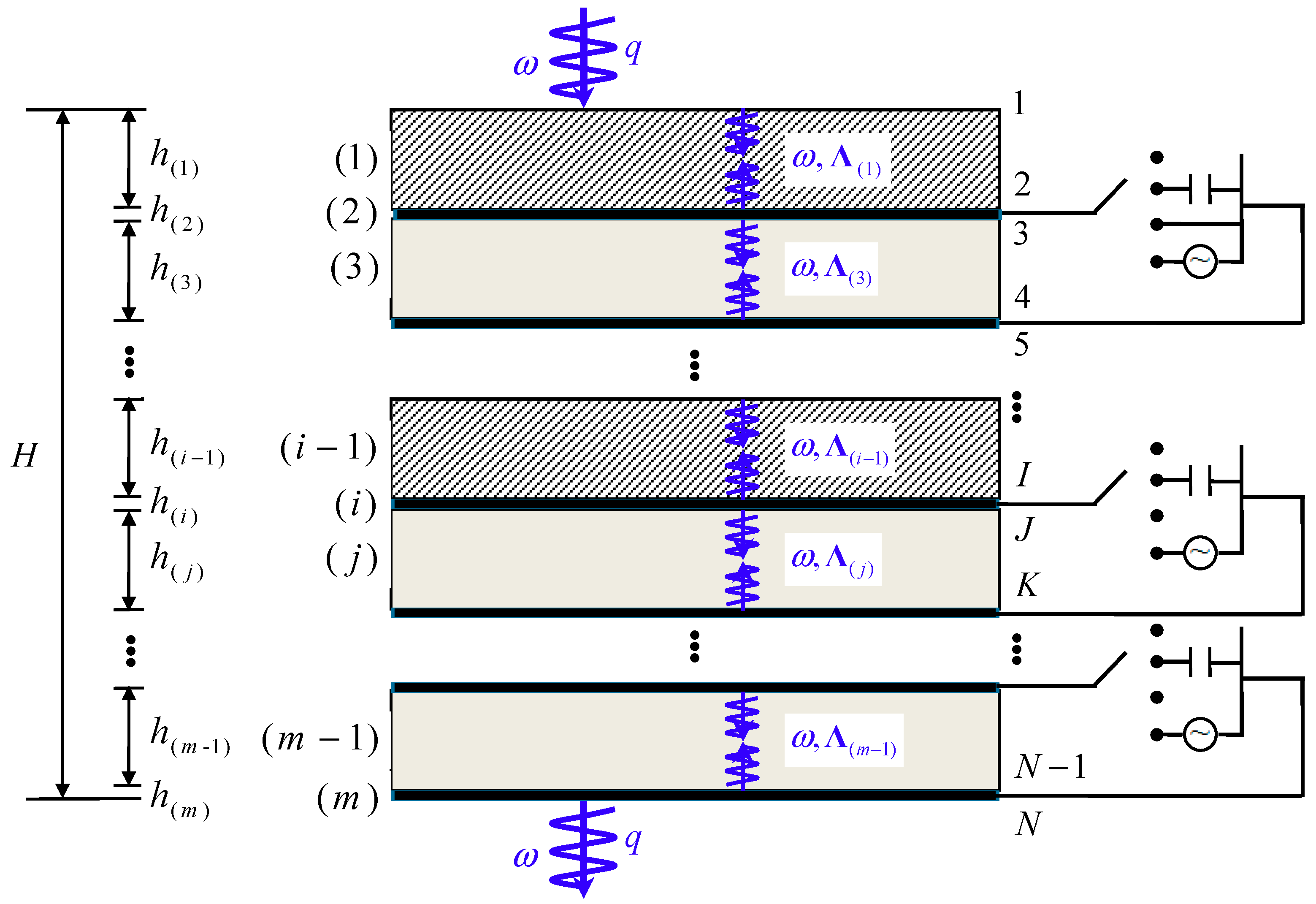
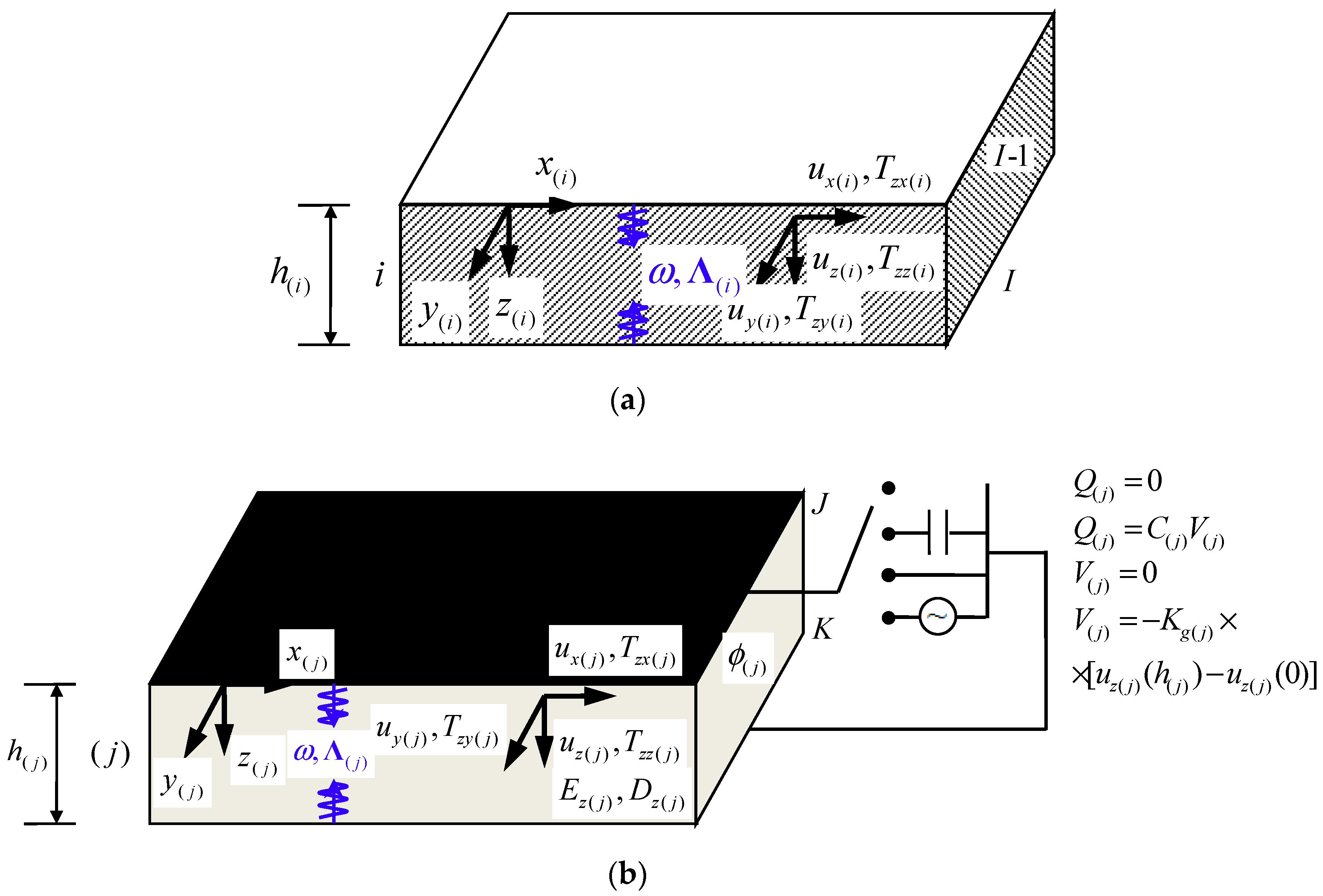
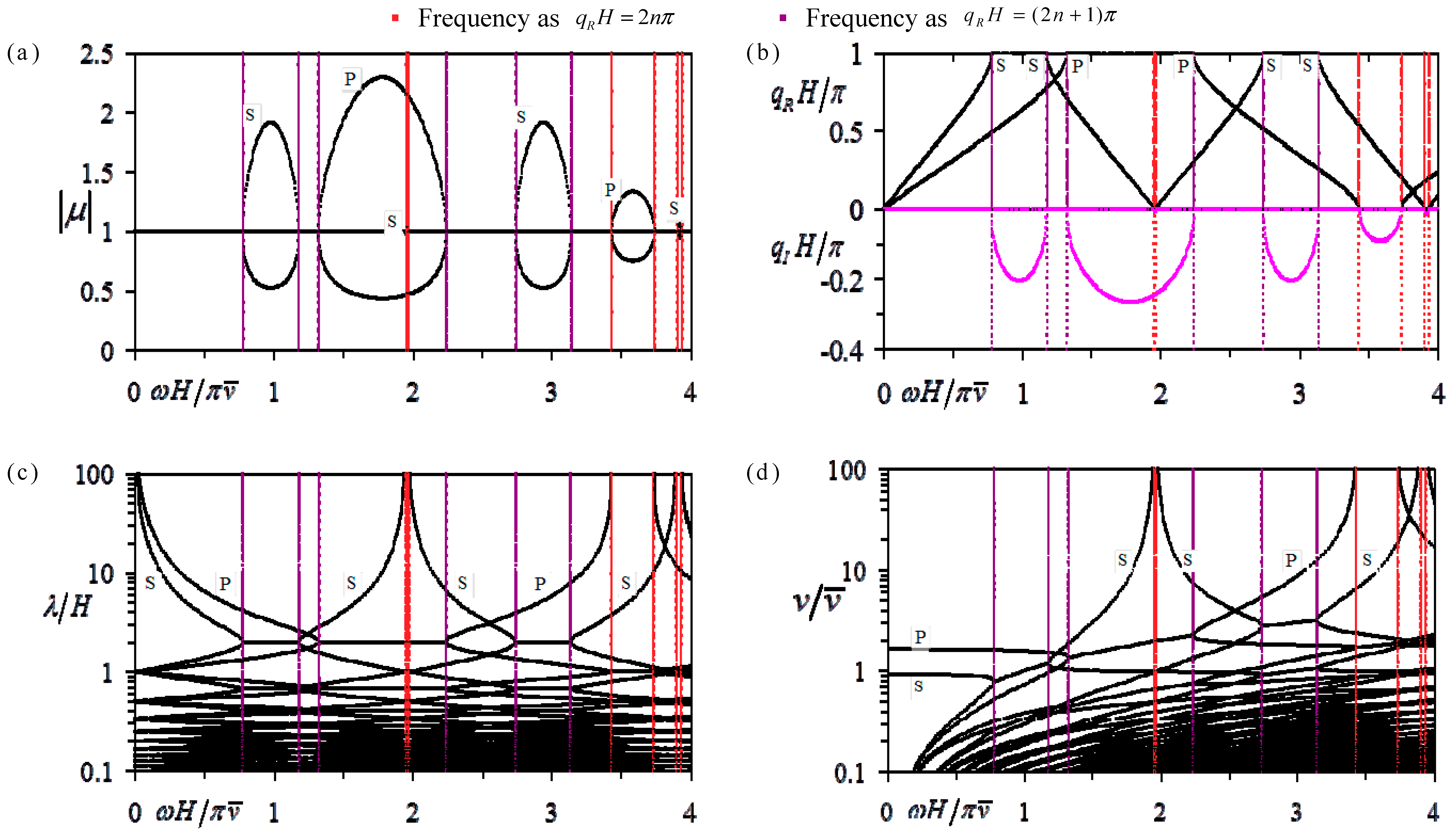
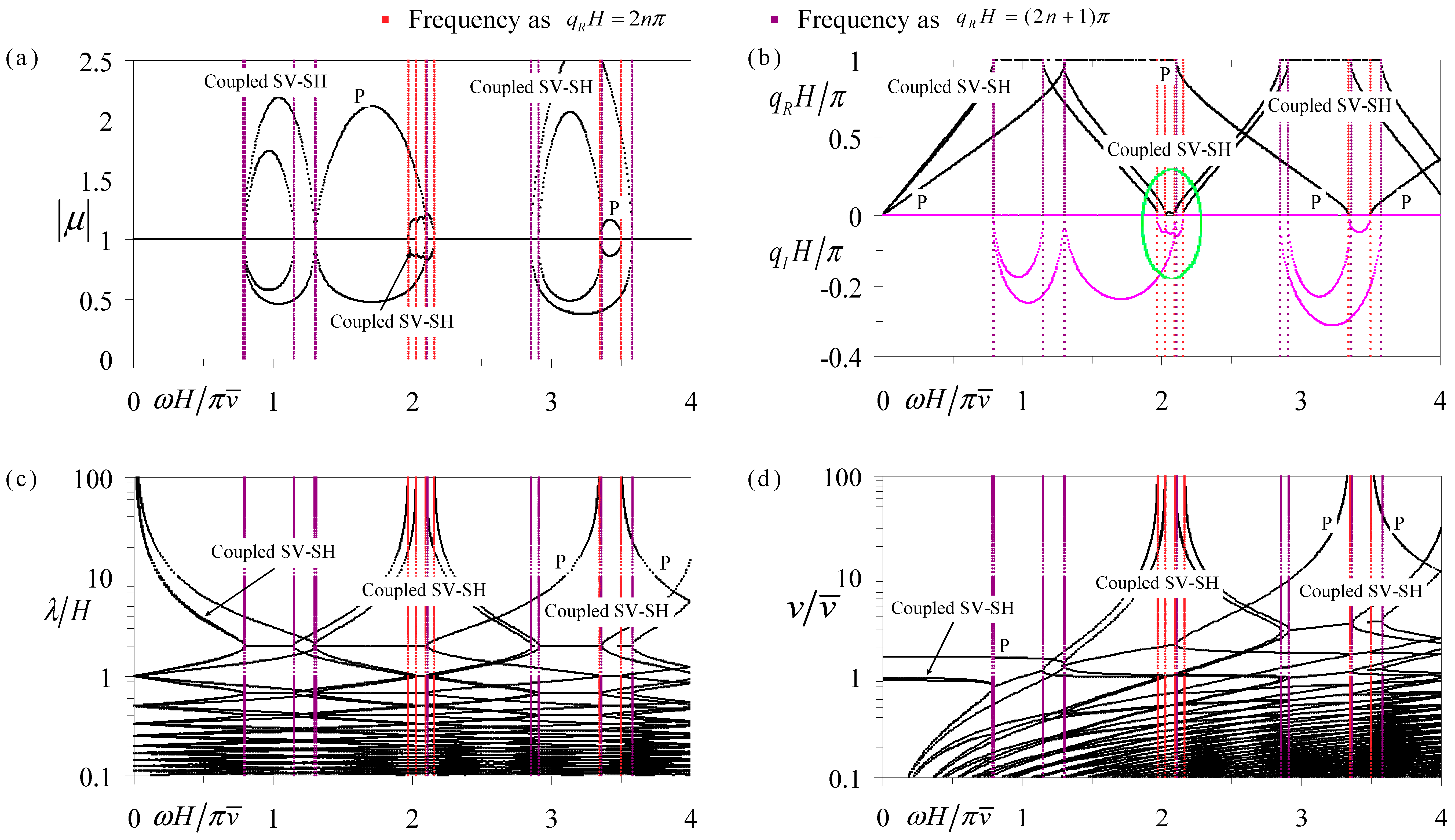
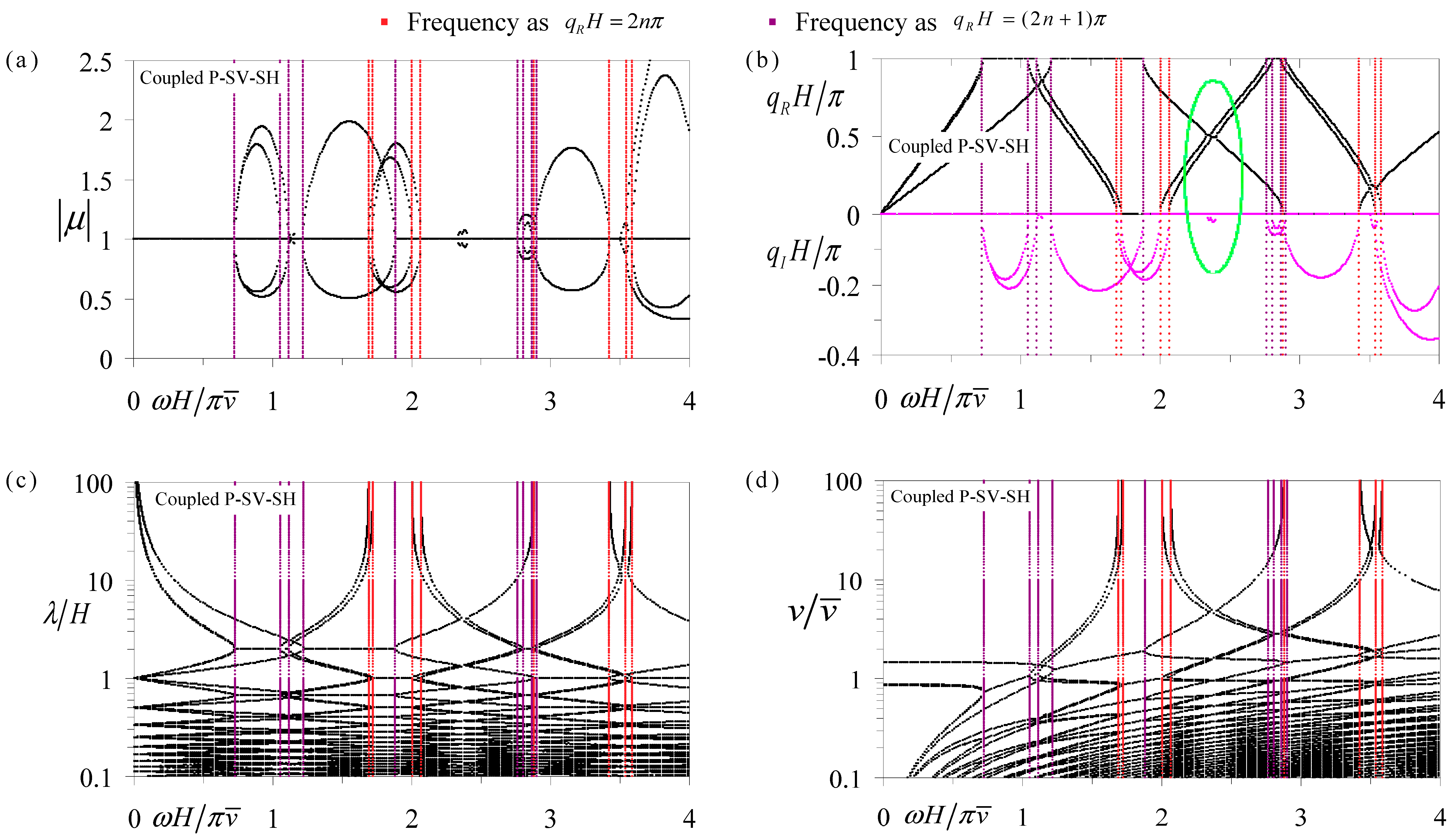
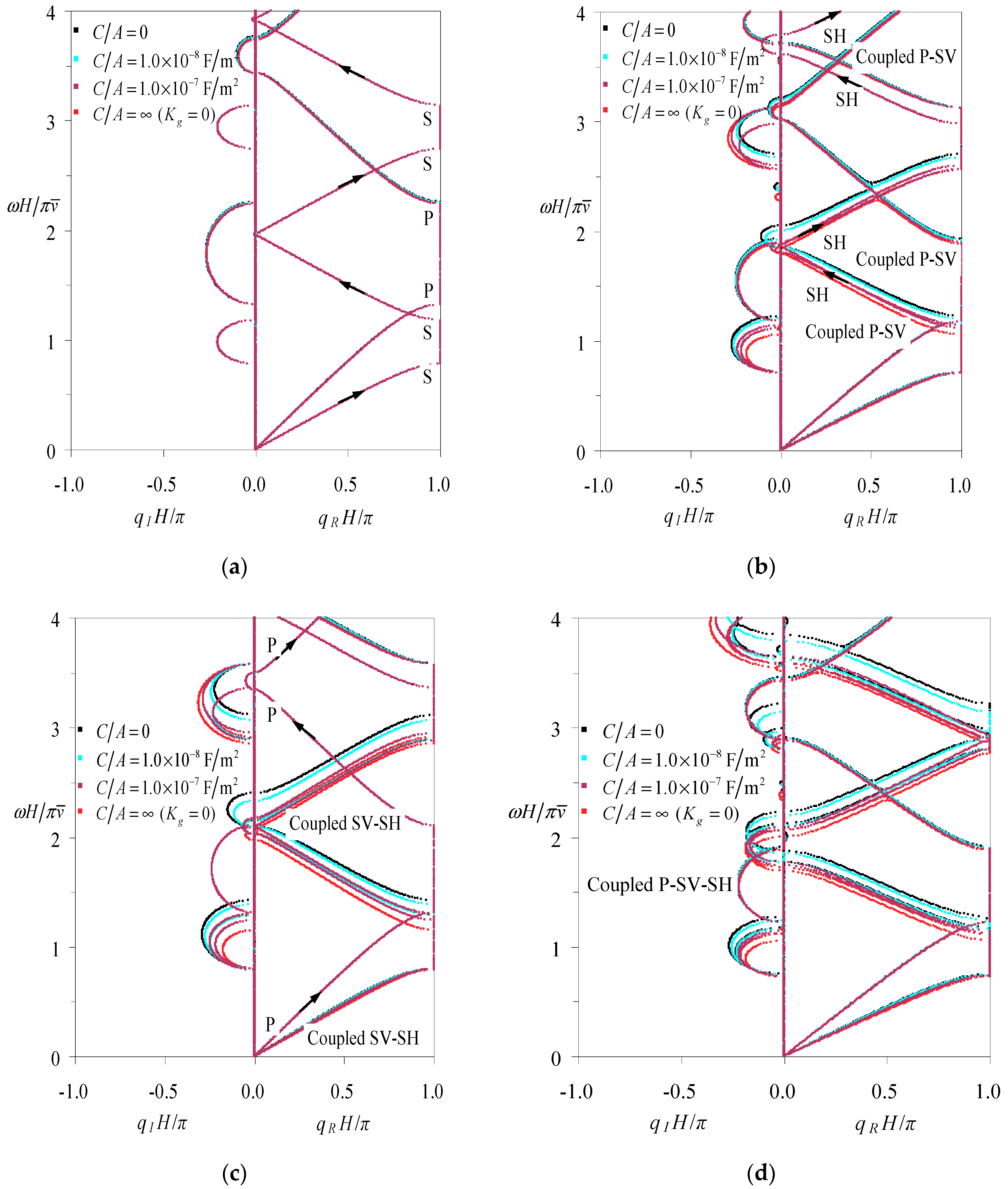
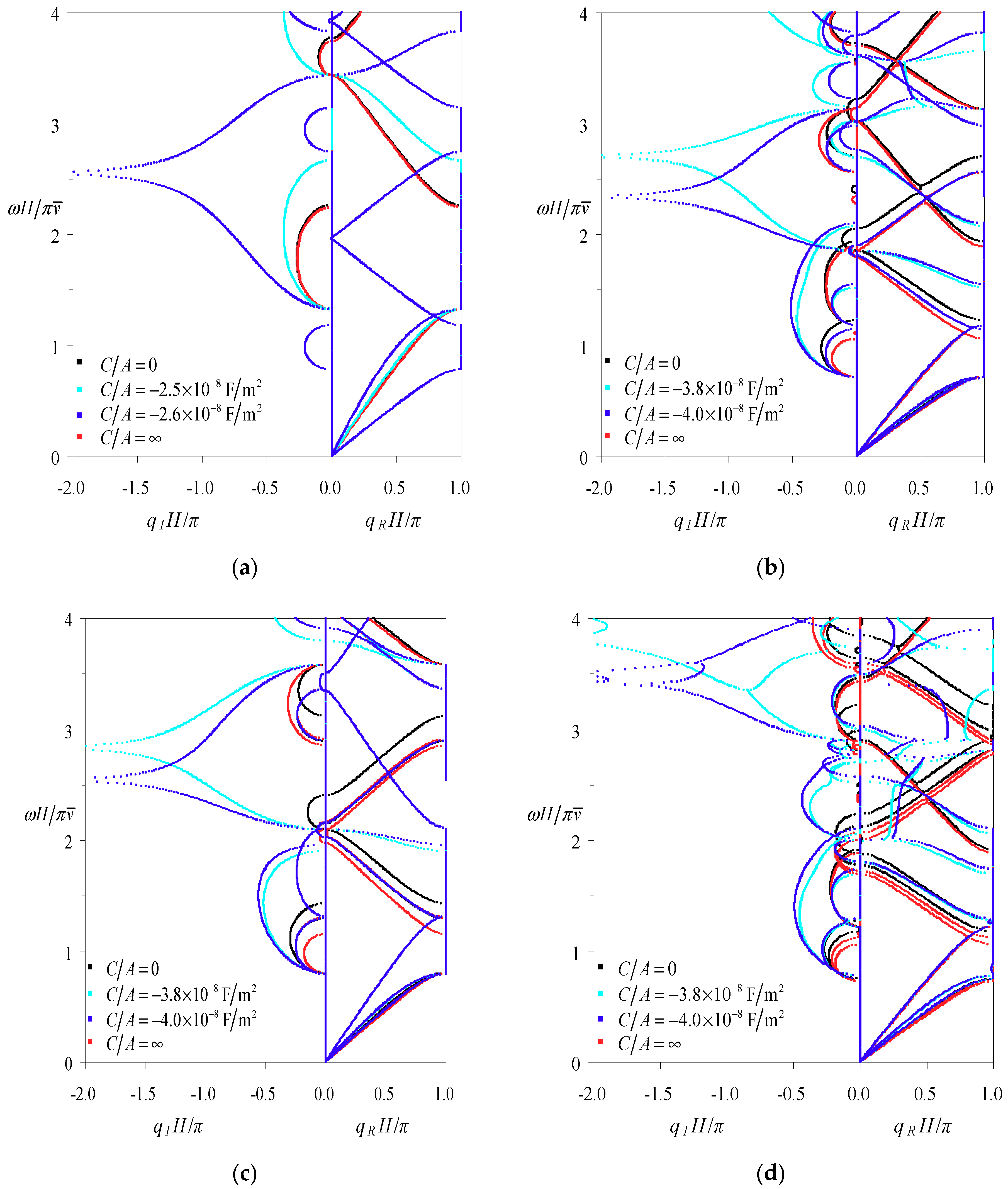
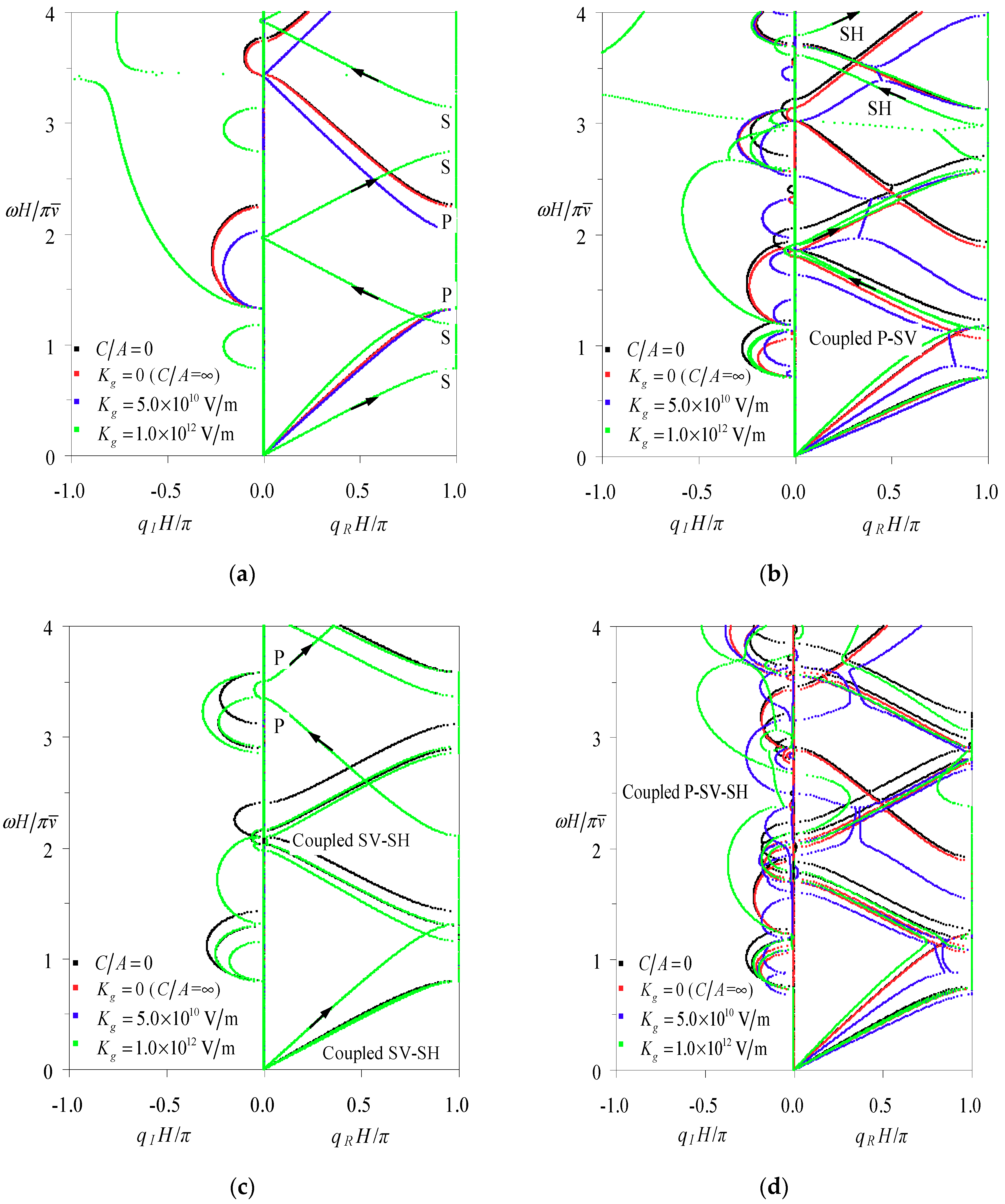
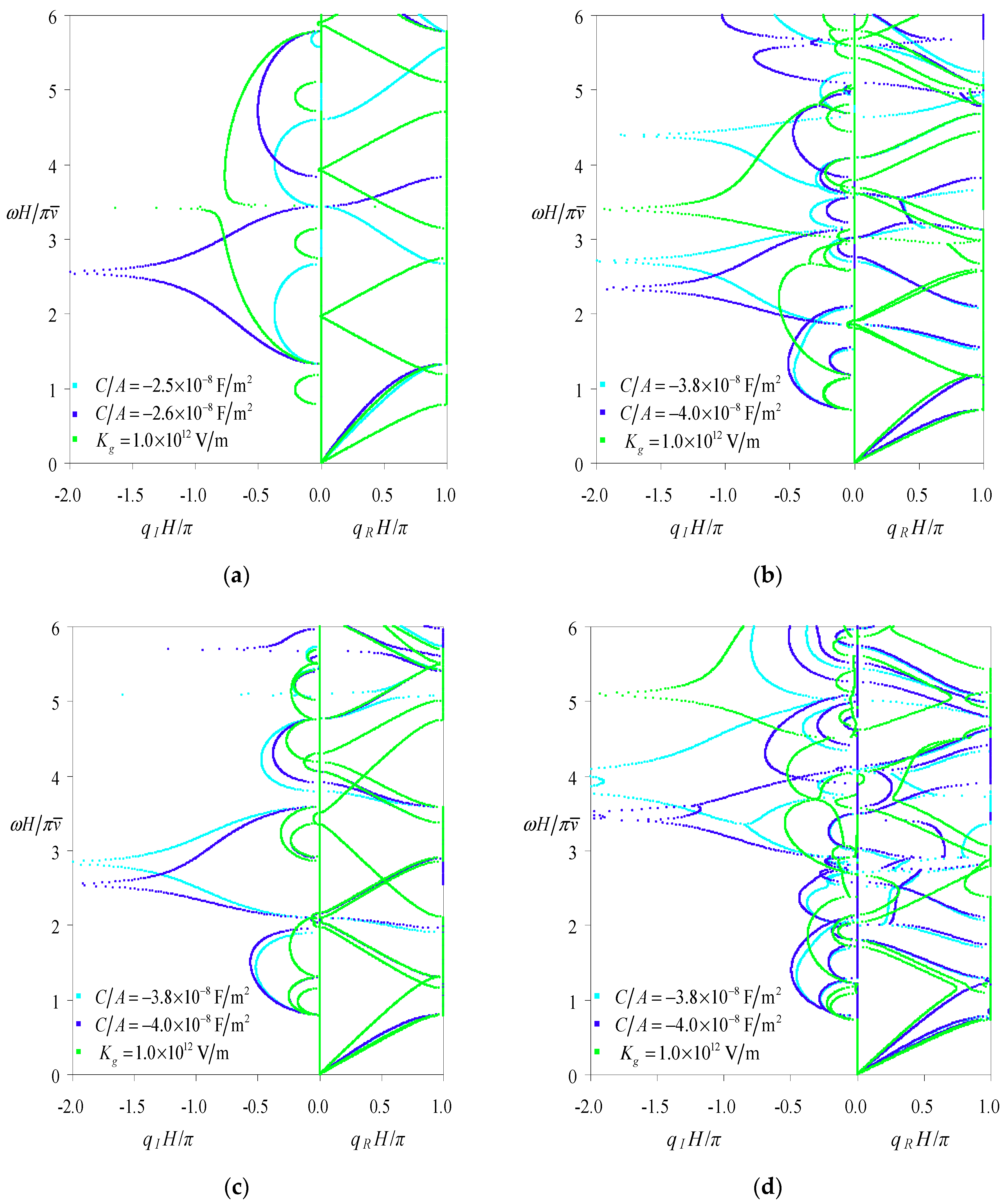
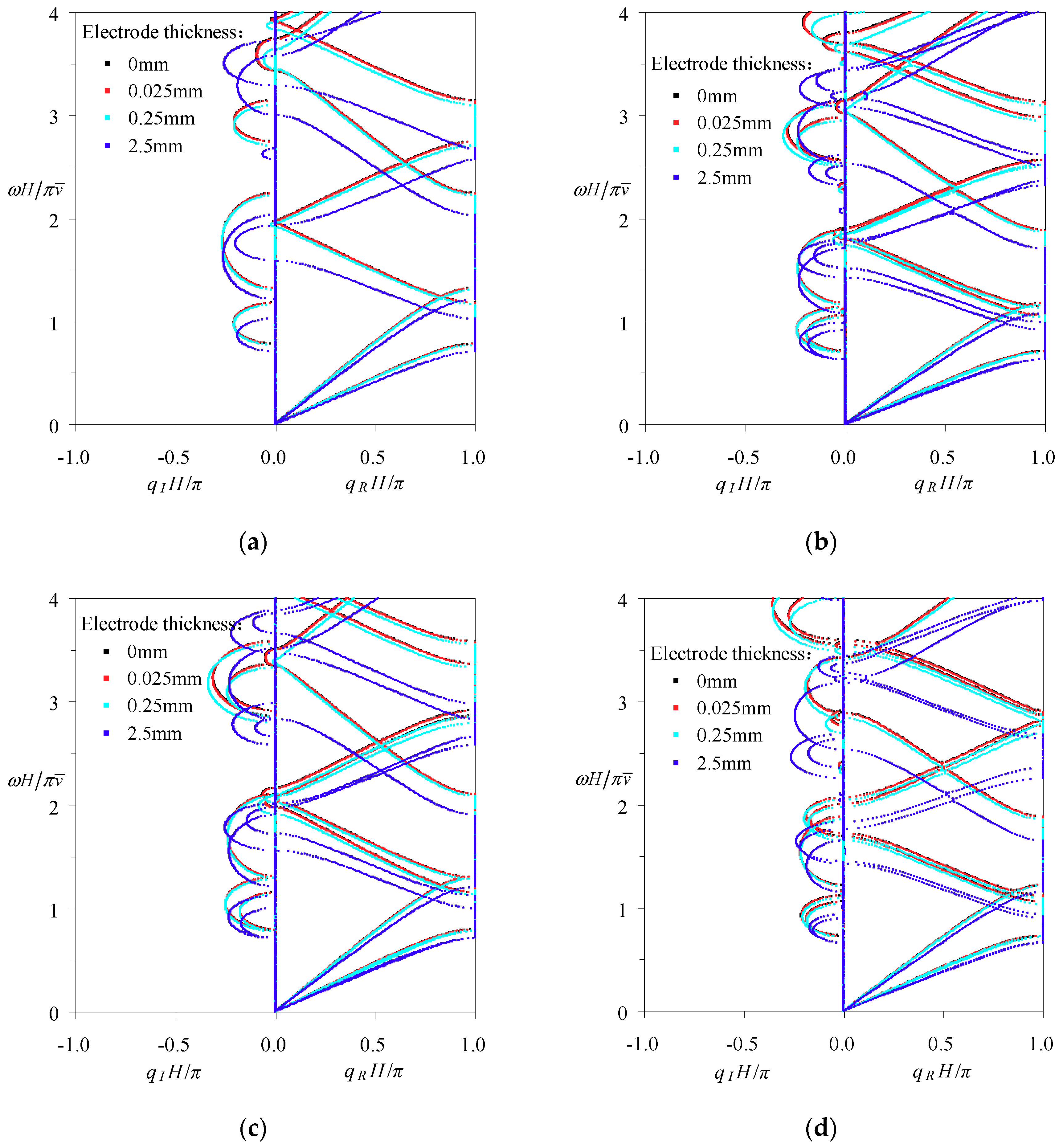
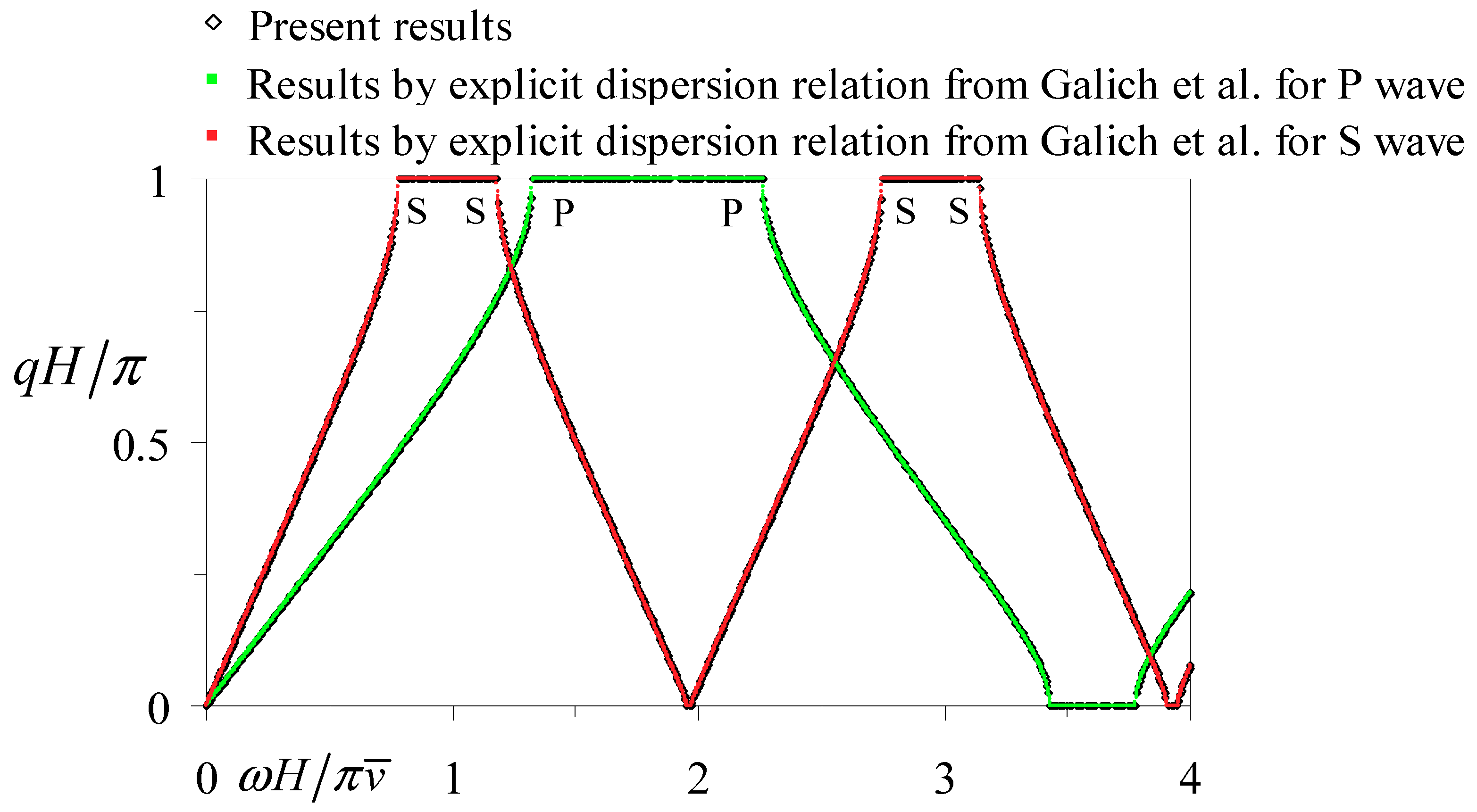
Table A1.
Expressions of relative electrical quantities in cases of four electrical boundaries.
| Electrical Boundaries | Electric-Open | Applied Capacitance | Electric-Short | Applied Feedback Control 1 |
|---|---|---|---|---|
| Mathematical relation | ||||
| Expressions of | ||||
| Expressions of | ||||
| Expressions of |
1.
Finally, substituting the expressions of into Equation (A1) gives,
i.e., Equation (16), where is naturally obtained from and represented by in cases of four electrical boundaries as also listed in Table A1.
Appendix B
In this section, the frequency–wavenumber spectra (band structures) of elastic waves along thickness in laminated piezoelectric phononic crystals with the unit cell consisting of Glass-LiNbO3A layers and the piezoelectric layer being in a state of electric open are analyzed by the formulation described above, so that the proposed method and the corresponding computer program can be validated in this degeneration situation. The elastic waves in this case are decoupled into pure SH, SV and P waves, so the computed results can be compared with their counterparts obtained by the explicit formula in Galich et al. [86] or identically in Shen & Cao [87], as provided in Figure A1. It is worth noting that the equivalent elastic constant is used for the LiNbO3A layer in the explicit formula so as to take its piezoelectric effect into account. From Figure A1, it is seen that the band structures gained by the two methods are exactly coincident, which proves our proposed method in this paper. Besides, note that the wavenumber spectra of the SH wave are superposed exactly on those of the SV wave due to the same wave speed.
Figure A1.
Comparisons of the wavenumber spectra for the periodic Glass-LiNbO3A multilayers with electric-open boundary computed by the proposed method and the explicit dispersion relation from Galich et al. [86].
Figure A1.
Comparisons of the wavenumber spectra for the periodic Glass-LiNbO3A multilayers with electric-open boundary computed by the proposed method and the explicit dispersion relation from Galich et al. [86].

References
- Lee, E.H.; Yang, W.H. On waves in composite materials with periodic structure. SIAM J. Appl. Math. 1973, 25, 492–499. [Google Scholar] [CrossRef]
- Hussein, M.I.; Leamy, M.J.; Ruzzene, M. Dynamics of phononic materials and structures: Historical origins, recent progress, and future outlook. ASME Appl. Mech. Rev. 2014, 66, 040802. [Google Scholar] [CrossRef]
- Banerjee, A.; Das, R.; Calius, E.P. Waves in structured mediums or metamaterials: A review. Arch. Computat. Methods Eng. 2018, 1–30. [Google Scholar] [CrossRef]
- Sapriel, J.; Djafari-Rouhani, B. Vibrations in superlattices. Surf. Sci. Rep. 1989, 10, 189–275. [Google Scholar] [CrossRef]
- Nougaoui, A.; Djafari-Rouhani, B. Vibrations in elastic and piezoelectric superlattices. J. Electron. Spectrosc. Relat. Phenom. 1987, 45, 197–206. [Google Scholar] [CrossRef]
- Deymier, P.A. Acoustic Metamaterials and Phononic Crystals; Springer: Berlin, Germany, 2013; pp. 1–12. [Google Scholar]
- Gomopoulos, N.; Maschke, D.; Koh, C.Y.; Thomas, E.L.; Tremel, W.; Butt, H.-J.; Fytas, G. One-dimensional hypersonic phononic crystals. Nano Lett. 2010, 10, 980–984. [Google Scholar] [CrossRef] [PubMed]
- Nemat-Nasser, S.; Sadeghi, H.; Amirkhizi, A.V.; Srivastava, A. Phononic layered composites for stress-wave attenuation. Mech. Res. Commun. 2015, 68, 65–69. [Google Scholar] [CrossRef] [Green Version]
- Srivastava, A. Metamaterial properties of periodic laminates. J. Mech. Phys. Solids 2016, 96, 252–263. [Google Scholar] [CrossRef]
- Datta, S.K.; Shah, A.H. Elastic Waves in Composite Media and Structures: With Applications to Ultrasonic Nondestructive Evaluation; CRC Press: Boca Raton, FL, USA, 2009; pp. 37–164. [Google Scholar]
- Shen, M.R.; Cao, W.W. Acoustic band-gap engineering using finite-size layered structures of multiple periodicity. Appl. Phys. Lett. 1999, 75, 3713–3715. [Google Scholar] [CrossRef] [Green Version]
- Nayfeh, A.H. The general problem of elastic wave propagation in multilayered anisotropic media. J. Acoust. Soc. Am. 1991, 89, 1521–1531. [Google Scholar] [CrossRef]
- Aly, A.H.; Mehaney, A.; Abdel-Rahman, E. Study of physical parameters on the properties of phononic band gaps. Int. J. Mod. Phys. B 2013, 27, 1350047. [Google Scholar] [CrossRef]
- Helbig, K. Anisotropy and dispersion in periodically layered media. Geophysics 1984, 49, 364–373. [Google Scholar] [CrossRef]
- Camley, R.E.; Djafari-Rouhani, B.; Dobrzynski, L.; Maradudin, A.A. Transverse elastic waves in periodically layered infinite, semi-infinite, and slab media. J. Vac. Sci. Technol. B 1983, 1, 371–375. [Google Scholar] [CrossRef]
- Auld, B.A.; Beaupre, G.S.; Herrmann, G. Horizontal shear surface waves on a laminated composite. Electron. Lett. 1977, 13, 525–527. [Google Scholar] [CrossRef]
- Bulgakov, A.A. Surface acoustic oscillations in a periodically layered medium. Solid State Commun. 1985, 55, 869–872. [Google Scholar] [CrossRef]
- Maréchal, P.; Haumesser, L.; Tran-Huu-Hue, L.P.; Holc, J.; Kuščer, D.; Lethiecq, M.; Feuillard, G. Modeling of a high frequency ultrasonic transducer using periodic structures. Ultrasonics 2008, 48, 141–149. [Google Scholar] [CrossRef] [PubMed]
- Royer, D.; Dieulesaint, E. Elastic Waves in Solids II: Generation, Acousto-optic Interaction, Applications; Springer: Berlin, Germany, 2000; ISBN 3-540-65931-5. [Google Scholar]
- Li, F.-M.; Wang, Y.-S. Study on wave localization in disordered periodic layered piezoelectric composite structures. Int. J. Solids Struct. 2005, 42, 6457–6474. [Google Scholar] [CrossRef] [Green Version]
- Li, F.-M.; Xu, M.-Q.; Wang, Y.-S. Frequency-dependent localization length of SH-wave in randomly disordered piezoelectric phononic crystals. Solid State Commun. 2007, 141, 296–301. [Google Scholar] [CrossRef]
- Li, F.-M.; Wang, Y.-S. Study on localization of plane elastic waves in disordered periodic 2-2 piezoelectric composite structures. J. Sound Vib. 2006, 296, 554–566. [Google Scholar] [CrossRef]
- Li, F.-M.; Wang, Y.-Z.; Fang, B.; Wang, Y.-S. Propagation and localization of two-dimensional in-plane elastic waves in randomly disordered layered piezoelectric phononic crystals. Int. J. Solids Struct. 2007, 44, 7444–7456. [Google Scholar] [CrossRef]
- Guo, X.; Wei, P.J. Dispersion relations of elastic waves in one-dimensional piezoelectric phononic crystal with initial stresses. Int. J. Mech. Sci. 2016, 106, 231–244. [Google Scholar] [CrossRef]
- Golub, M.V.; Fomenko, S.I.; Alexandrov, A.A. Simulation of plane 3D wave propagation in layered piezoelectric phononic crystals. In Proceedings of the International Conference Days on Diffraction (DD) 2014, St. Petersburg, Russia, 26–30 May 2014; IEEE: Piscataway, NJ, USA, 2014; pp. 83–88. [Google Scholar] [CrossRef]
- Fomenko, S.I.; Golub, M.V.; Alexandrov, A.A.; Chen, A.L.; Wang, Y.S.; Zhang, Ch. Band-gaps and low transmission pass-bands in layered piezoelectric phononic crystals. In Proceedings of the International Conference Days on Diffraction (DD) 2016, St. Petersburg, Russia, 27 June–1 July 2016; IEEE: Piscataway, NJ, USA, 2016; pp. 149–154. [Google Scholar] [CrossRef]
- Fomenko, S.I.; Golub, M.V.; Chen, A.L.; Wang, Y.S.; Zhang, C.Z. Band-gap and pass-band classification for oblique waves propagating in a three-dimensional layered functionally graded piezoelectric phononic crystal. J. Sound Vib. 2019, 439, 219–240. [Google Scholar] [CrossRef]
- Chen, A.-L.; Yan, D.-J.; Wang, Y.-S.; Zhang, C.Z. Anti-plane transverse waves propagation in nanoscale periodic layered piezoelectric structures. Ultrasonics 2016, 65, 154–164. [Google Scholar] [CrossRef] [PubMed] [Green Version]
- Yan, D.-J.; Chen, A.-L.; Wang, Y.-S.; Zhang, C.Z.; Golub, M. In-plane elastic wave propagation in nanoscale periodic layered piezoelectric structures. Int. J. Mech. Sci. 2018, 142, 276–288. [Google Scholar] [CrossRef]
- Zinchuk, L.P.; Podlipenets, A.N.; Shul’ga, N.A. Electroelastic shear waves in a stratified periodic medium. Sov. Appl. Mech. 1988, 24, 245–250. [Google Scholar] [CrossRef]
- Zinchuk, L.P.; Levchenko, V.V.; Shul’ga, N.A. Propagation of three-dimensional electroelastic shear waves in a regularly layered medium of metal-piezoelectric type. J. Math. Sci. 1993, 63, 298–302. [Google Scholar] [CrossRef]
- Alshits, V.I.; Shuvalov, A.L. Resonance reflection and transmission of shear elastic waves in multilayered piezoelectric structures. J. Appl. Phys. 1995, 77, 2659–2665. [Google Scholar] [CrossRef]
- Qian, Z.H.; Jin, F.; Wang, Z.K.; Kishimoto, K. Dispersion relations for SH-wave propagation in periodic piezoelectric composite layered structures. Int. J. Eng. Sci. 2004, 42, 673–689. [Google Scholar] [CrossRef]
- Lan, M.; Wei, P.J. Laminated piezoelectric phononic crystal with imperfect interfaces. J. Appl. Phys. 2012, 111, 013505. [Google Scholar] [CrossRef]
- Faidi, W.I.; Nayfeh, A.H. An improved model for wave propagation in laminated piezoelectric composites. Mech. Mater. 2000, 32, 235–241. [Google Scholar] [CrossRef]
- Geng, X.C.; Zhang, Q.M. Evaluation of piezocomposites for ultrasonic transducer applications—Influence of the unit cell dimensions and the properties of constituents on the performance of 2-2 piezocomposites. IEEE Trans. Ultrason. Ferroelectr. Freq. Control 1997, 44, 857–872. [Google Scholar] [CrossRef]
- Podlipenets, A.N. Wave propagation in periodically layered elastic and electroelastic media. In IUTAM Symposium on Anisotropy, Inhomogeneity and Nonlinearity in Solid Mechanics, Nottingham, UK, 30 August–3 September 1994; Solid Mechanics and Its Applications book series (SMIA, volume 39); Parker, D.F., England, A.H., Eds.; Springer: Dordrecht, The Netherlands, 1995; pp. 469–474. [Google Scholar]
- Zinchuk, L.P.; Podlipenets, A.N.; Shul’ga, N.A. Surface and normal electroelastic shear waves in even-layered structures. J. Math. Sci. 1995, 74, 1157–1162. [Google Scholar] [CrossRef]
- Yan, D.-J.; Chen, A.-L.; Wang, Y.-S.; Zhang, C.Z.; Golub, M. Propagation of guided elastic waves in nanoscale layered periodic piezoelectric composites. Eur. J. Mech. A Solids 2017, 66, 158–167. [Google Scholar] [CrossRef]
- Wang, Y.-Z.; Li, F.-M.; Huang, W.-H.; Wang, Y.-S. The propagation and localization of Rayleigh waves in disordered piezoelectric phononic crystals. J. Mech. Phys. Solids 2008, 56, 1578–1590. [Google Scholar] [CrossRef]
- Alippi, A.; Craciun, F.; Molinari, E. Stopband edges in the dispersion curves of Lamb waves propagating in piezoelectric periodical structures. Appl. Phys. Lett. 1988, 53, 1806–1808. [Google Scholar] [CrossRef]
- Craciun, F.; Sorba, L.; Molinari, E.; Pappalardo, M. A coupled-mode theory for periodic piezoelectric composites. IEEE Trans. Ultrason. Ferroelectr. Freq. Control 1989, 36, 50–56. [Google Scholar] [CrossRef] [PubMed]
- Guo, X.; Wei, P.J.; Li, L. Dispersion relations of elastic waves in one-dimensional piezoelectric phononic crystal with mechanically and dielectrically imperfect interfaces. Mech. Mater. 2016, 93, 168–183. [Google Scholar] [CrossRef] [Green Version]
- Ghazaryan, K.B.; Piliposyan, D.G. Interfacial effects for shear waves in one dimensional periodic piezoelectric structure. J. Sound Vib. 2011, 330, 6456–6466. [Google Scholar] [CrossRef]
- Zhao, J.; Pan, Y.; Zhong, Z. Theoretical study of shear horizontal wave propagation in periodically layered piezoelectric structure. J. Appl. Phys. 2012, 111, 064906. [Google Scholar] [CrossRef]
- Zhao, J.; Pan, Y.; Zhong, Z. A study of pressure-shear vertical wave propagation in periodically layered fluid and piezoelectric structure. J. Appl. Phys. 2013, 113, 054903. [Google Scholar] [CrossRef]
- Zinchuk, L.P.; Podlipenets, A.N.; Shul’ga, N.A. Dispersion relations for electroelastic shear waves in a periodically layered medium. Sov. Appl. Mech. 1990, 26, 1092–1099. [Google Scholar] [CrossRef]
- Zinchuk, L.P.; Podlipenets, A.N. Vibrational modes in a surface shear wave propagating in a regularly layered electroelastic half-space. Sov. Appl. Mech. 1991, 27, 775–779. [Google Scholar] [CrossRef]
- Zinchuk, L.P.; Podlipenets, A.N. Dispersion equations for Rayleigh waves in a piezoelectric periodically layered structure. J. Math. Sci. 2001, 103, 398–403. [Google Scholar] [CrossRef]
- Alami, M.; El Boudouti, E.H.; Djafari-Rouhani, B.; El Hassouani, Y.; Talbi, A. Surface acoustic waves in one-dimensional piezoelectric-metallic phononic crystal: Effect of a cap layer. Ultrasonics 2018, 90, 80–97. [Google Scholar] [CrossRef] [PubMed]
- Otero, J.A.; Rodríguez-Ramos, R.; Monsivais, G.; Pérez-Alvarez, R. Dynamical behavior of a layered piezocomposite using the asymptotic homogenization method. Mech. Mater. 2005, 37, 33–44. [Google Scholar] [CrossRef]
- Zou, X.-Y.; Chen, Q.; Cheng, J.-C. The band gaps of plate-mode waves in one-dimensional piezoelectric composite plates: Polarizations and boundary conditions. IEEE Trans. Ultrason. Ferroelectr. Freq. Control 2007, 54, 1430–1436. [Google Scholar] [CrossRef] [PubMed]
- Zhu, Y.-F.; Yuan, Y.; Zou, X.-Y.; Cheng, J.-C. Piezoelectric-sensitive mode of lamb wave in one-dimensional piezoelectric phononic crystal plate. Wave Motion 2015, 54, 66–75. [Google Scholar] [CrossRef]
- Piliposyan, D.G.; Piliposian, G.T.; Ghazaryan, K.B. Propagation and control of shear waves in piezoelectric composite waveguides with metallized interfaces. Int. J. Solids Struct. 2017, 106, 119–128. [Google Scholar] [CrossRef]
- Li, Q.Q.; Guo, Y.Q.; Wang, J.Y.; Chen, W. Band structures analysis of elastic waves propagating along thickness direction in periodically laminated piezoelectric composites. Crystals 2018, 8, 351. [Google Scholar] [CrossRef]
- Ponge, M.-F.; Dubus, B.; Granger, C.; Vasseur, J.O.; Thi, M.P.; Hladky-Hennion, A.-C. Theoretical and experimental analyses of tunable Fabry-Perot resonators using piezoelectric phononic crystals. IEEE Trans. Ultrason. Ferroelectr. Freq. Control 2015, 62, 1114–1121. [Google Scholar] [CrossRef]
- Ponge, M.F.; Dubus, B.; Granger, C.; Vasseur, J.; Thi, M.P.; Hladky-Hennion, A.-C. Optimization of a tunable piezoelectric resonator using phononic crystals with periodic electrical boundary conditions. Phys. Proc. 2015, 70, 258–261. [Google Scholar] [CrossRef]
- Kutsenko, A.A.; Shuvalov, A.L.; Poncelet, O.; Darinskii, A.N. Quasistatic stopband and other unusual features of the spectrum of a one-dimensional piezoelectric phononic crystal controlled by negative capacitance. C. R. Mecanique 2015, 343, 680–688. [Google Scholar] [CrossRef]
- Kutsenko, A.A.; Shuvalov, A.L.; Poncelet, O.; Darinskii, A.N. Quasistatic stopband in the spectrum of one-dimensional piezoelectric phononic crystal. arXiv 2015, arXiv:1410.7215v2. [Google Scholar]
- Kutsenko, A.A.; Shuvalov, A.L.; Poncelet, O.; Darinskii, A.N. Tunable effective constants of the one-dimensional piezoelectric phononic crystal with internal connected electrodes. J. Acoust. Soc. Am. 2015, 137, 606–616. [Google Scholar] [CrossRef] [PubMed]
- Kutsenko, A.A.; Shuvalov, A.L.; Poncelet, O. Dispersion spectrum of acoustoelectric waves in 1D piezoelectric crystal coupled with 2D infinite network of capacitors. J. Appl. Phys. 2018, 123, 044902. [Google Scholar] [CrossRef] [Green Version]
- Mansoura, S.A.; Morvan, B.; Maréchal, P.; Hladky-Hennion, A.-C.; Dubus, B. Study of an hybridization gap in a one dimensional piezoelectric phononic crystal. Phys. Procedia 2015, 70, 279–282. [Google Scholar] [CrossRef]
- Zhu, X.H.; Qiao, J.; Zhang, G.Y.; Zhou, Q.; Wu, Y.D.; Li, L.Q. Tunable acoustic metamaterial based on piezoelectric ceramic transducer. In Proceedings of the Active and Passive Smart Structures and Integrated Systems 2017, SPIE 10164, SPIE Smart Structures and Materials+Nondestructive Evaluation and Health Monitoring 2017, Portland, OR, USA, 25–29 March; Park, G., Erturk, A., Han, J.-H., Eds.; SPIE: Bellingham, WA, USA, 2017; p. 1016411. [Google Scholar]
- Parra, E.A.F.; Bergamini, A.; Lossouarn, B.; Damme, B.V.; Cenedese, M.; Ermanni, P. Bandgap control with local and interconnected LC piezoelectric shunts. Appl. Phys. Lett. 2017, 111, 111902. [Google Scholar] [CrossRef] [Green Version]
- Fomenko, S.I.; Golub, M.V.; Doroshenko, O.V.; Chen, A.-L.; Wang, Y.-S.; Zhang, C.Z. Wave motion in piezoelectric layered phononic crystals with and without electroded surfaces. In Proceedings of the International Conference Days on Diffraction (DD) 2017, St. Petersburg, Russia, 19–23 June 2017; IEEE: Piscataway, NJ, USA, 2017; pp. 116–121. [Google Scholar] [CrossRef]
- Mansoura, S.A.; Maréchal, P.; Morvan, B.; Hladky-Hennion, A.C.; Dubus, B. Active control of a piezoelectric phononic crystal using electrical impedance. In Proceedings of the 2014 IEEE International Ultrasonics Symposium (IUS), Chicago, IL, USA, 3–6 September 2014; IEEE: Piscataway, NJ, USA, 2014; pp. 951–954. [Google Scholar] [CrossRef]
- Mansoura, S.A.; Maréchal, P.; Morvan, B.; Dubus, B. Analysis of a phononic crystal constituted of piezoelectric layers using electrical impedance measurement. Phys. Procedia 2015, 70, 283–286. [Google Scholar] [CrossRef]
- Mansoura, S.A.; Morvan, B.; Maréchal, P.; Benard, P.; Lhadky-Hennion, A.-C.; Dubus, B. Tunability of the band structure of a piezoelectric phononic crystal using electrical negative capacitance. In Proceedings of the 2015 IEEE International Ultrasonics Symposium (IUS), Taipei, Taiwan, 21–24 October 2015; IEEE: Piscataway, NJ, USA, 2015; pp. 1–4. [Google Scholar] [CrossRef]
- Darinskii, A.N.; Shuvalov, A.L.; Poncelet, O.; Kutsenko, A.A. Bulk longitudinal wave reflection/transmission in periodic piezoelectric structures with metallized interfaces. Ultrasonics 2015, 63, 118–125. [Google Scholar] [CrossRef]
- Allam, A.; Elsabbagh, A.; Akl, W. Experimental demonstration of one-dimensional active plate-type acoustic metamaterial with adaptive programmable density. J. Appl. Phys. 2017, 121, 125106. [Google Scholar] [CrossRef]
- Wang, Y.L.; Song, W.; Sun, E.W.; Zhang, R.; Cao, W.W. Tunable passband in one-dimensional phononic crystal containing a piezoelectric 0.62Pb(Mg1/3Nb2/3)O3-0.38PbTiO3 single crystal defect layer. Physica E 2014, 60, 37–41. [Google Scholar] [CrossRef]
- Chopra, I. Review of state of art of smart structures and integrated systems. AIAA J. 2002, 40, 2145–2187. [Google Scholar] [CrossRef]
- Song, G.; Sethi, V.; Li, H.-N. Vibration control of civil structures using piezoceramic smart materials: A review. Eng. Struct. 2006, 28, 1513–1524. [Google Scholar] [CrossRef]
- Honein, B.; Braga, A.M.B.; Barbone, P.; Herrmann, G. Wave propagation in piezoelectric layered media with some applications. J. Intell. Mater. Syst. Struct. 1991, 2, 542–557. [Google Scholar] [CrossRef]
- Minagawa, S. Propagation of harmonic waves in a layered elasto-piezoelectric composite. Mech. Mater. 1995, 19, 165–170. [Google Scholar] [CrossRef]
- Pestel, E.C.; Leckie, F.A. Matrix Methods in Elasto Mechanics; McGraw-Hill: New York, NY, USA, 1963; ISBN 0-070-49520-3. [Google Scholar]
- Tarn, J.Q. A state space formalism for piezothermoelasticity. Int. J. Solids Struct. 2002, 39, 5173–5184. [Google Scholar] [CrossRef]
- Mead, D.J. Wave propagation in continuous periodic structures: Research contributions from Southampton, 1964–1995. J. Sound Vib. 1996, 190, 495–524. [Google Scholar] [CrossRef]
- Brillouin, L. Wave Propagation in Periodic Structures: Electric Filters and Crystal Lattices, 2nd ed.; Dover Publications: Mineola, NY, USA, 1953. [Google Scholar]
- ANSI/IEEE Std 176-1987. IEEE Standard on Piezoelectricity; IEEE: New York, NY, USA, 1988; pp. 3–30. ISBN 0-7381-2411-7. [Google Scholar]
- Tiersten, H.F. Linear Piezoelectric Plate Vibrations; Plenum Press: New York, NY, USA, 1969; pp. 33–39. ISBN 978-1-4899-6221-8. [Google Scholar]
- Auld, B.A. Acoustic Fields and Waves in Solids; John Wiley & Sons: New York, NY, USA, 1973; Volume 1, pp. 101–134. ISBN 0-471-03700-1. [Google Scholar]
- Kochervinskiǐ, V.V. Piezoelectricity in crystallizing ferroelectric polymers: Poly(vinylidene fluoride) and its copolymers (a review). Crystallogr. Rep. 2003, 48, 649–675. [Google Scholar] [CrossRef]
- Cardarelli, F. Materials Handbook: A Concise Desktop Reference, 2nd ed.; Springer: London, UK, 2008; pp. 184–186. [Google Scholar]
- Li, L.F.; Guo, Y.Q. Analysis of longitudinal waves in rod-type piezoelectric phononic crystals. Crystals 2016, 6, 45. [Google Scholar] [CrossRef]
- Galich, P.I.; Fang, N.X.; Boyce, M.C.; Rudykh, S. Elastic wave propagation in finitely deformed layered materials. J. Mech. Phys. Solids 2017, 98, 390–410. [Google Scholar] [CrossRef]
- Shen, M.R.; Cao, W.W. Acoustic bandgap formation in a periodic structure with multilayer unit cells. J. Phys. D Appl. Phys. 2000, 33, 1150–1154. [Google Scholar] [CrossRef]
- Guo, Y.Q.; Fang, D.N. Analysis and interpretation of longitudinal waves in periodic multiphase rods using the method of reverberation-ray matrix combined with the Floquet-Bloch theorem. J. Vib. Acoust. 2014, 136, 011006. [Google Scholar] [CrossRef]
Figure 1.
The unit cell of the general periodically laminated piezoelectric composite structures with arbitrarily anisotropic constituent interlayers and the description about the propagation characteristics of coupled elastic waves along thickness direction.
Figure 1.
The unit cell of the general periodically laminated piezoelectric composite structures with arbitrarily anisotropic constituent interlayers and the description about the propagation characteristics of coupled elastic waves along thickness direction.

Figure 2.
The descriptions of the local coordinate systems and the physical quantities of typical elastic/piezoelectric layers in the unit cell. (a) A typical elastic layer. (b) A typical piezoelectric layer covered by the electrode layers with four electrical boundaries: electric-open, applied capacitance, electric-short, and applied feedback control.

Figure 3.
The comprehensive frequency-related dispersion curves of the uncoupled elastic waves in periodic Glass-Brass-LiNbO3A-Brass multilayers with electric-short boundary: (a) eigenvalue amplitude spectra; (b) wavenumber spectra; (c) wavelength spectra; (d) phase velocity spectra.
Figure 3.
The comprehensive frequency-related dispersion curves of the uncoupled elastic waves in periodic Glass-Brass-LiNbO3A-Brass multilayers with electric-short boundary: (a) eigenvalue amplitude spectra; (b) wavenumber spectra; (c) wavelength spectra; (d) phase velocity spectra.

Figure 4.
The comprehensive frequency-related dispersion curves of the coupled P-SV and pure SH waves in periodic Glass-Brass-LiNbO3B-Brass multilayers with electric-short boundary: (a) eigenvalue amplitude spectra; (b) wavenumber spectra; (c) wavelength spectra; (d) phase velocity spectra.
Figure 4.
The comprehensive frequency-related dispersion curves of the coupled P-SV and pure SH waves in periodic Glass-Brass-LiNbO3B-Brass multilayers with electric-short boundary: (a) eigenvalue amplitude spectra; (b) wavenumber spectra; (c) wavelength spectra; (d) phase velocity spectra.

Figure 5.
The comprehensive frequency-related dispersion curves of the coupled SV-SH and pure P waves in periodic Glass-Brass-LiNbO3C-Brass multilayers with electric-short boundary: (a) The eigenvalue amplitude spectra; (b) The wavenumber spectra; (c) The wavelength spectra; (d) The phase velocity spectra.

Figure 6.
The comprehensive frequency-related dispersion curves of the coupled P-SV-SH waves in periodic Glass-Brass-LiNbO3B-Brass-LiNbO3C-Brass multilayers with electric-short boundary: (a) eigenvalue amplitude spectra; (b) wavenumber spectra; (c) wavelength spectra; (d) phase velocity spectra.
Figure 6.
The comprehensive frequency-related dispersion curves of the coupled P-SV-SH waves in periodic Glass-Brass-LiNbO3B-Brass-LiNbO3C-Brass multilayers with electric-short boundary: (a) eigenvalue amplitude spectra; (b) wavenumber spectra; (c) wavelength spectra; (d) phase velocity spectra.

Figure 7.
The influence of the applied capacitance on the band structures of the uncoupled and coupled elastic waves in periodic anisotropic piezoelectric composites with the unit cell consisting of (a) Glass-Brass-LiNbO3A-Brass, (b) Glass-Brass-LiNbO3B-Brass, (c) Glass-Brass-LiNbO3C-Brass, and (d) Glass-Brass-LiNbO3B-Brass-LiNbO3C-Brass.

Figure 8.
The variation of the band structures of uncoupled and coupled elastic waves when the applied negative capacitance is at the vicinity of the singular point in periodic anisotropic piezoelectric composites with the unit cell consisting of (a) Glass-Brass-LiNbO3A-Brass, (b) Glass-Brass-LiNbO3B-Brass, (c) Glass-Brass-LiNbO3C-Brass, and (d) Glass-Brass-LiNbO3B-Brass-LiNbO3C-Brass.

Figure 9.
The influence of the gain coefficient in the applied feedback control condition on the band structures of the uncoupled and coupled elastic waves in periodic anisotropic piezoelectric composites with the unit cell consisting of (a) Glass-Brass-LiNbO3A-Brass, (b) Glass-Brass-LiNbO3B-Brass, (c) Glass-Brass-LiNbO3C-Brass, and (d) Glass-Brass-LiNbO3B-Brass-LiNbO3C-Brass.

Figure 10.
The comparison of the band structures associated with the applied feedback control condition of big gain coefficient () and those associated with the applied negative capacitance near the singular point in periodic anisotropic piezoelectric composites as the unit cell consisting of (a) Glass-Brass-LiNbO3A-Brass, (b) Glass-Brass-LiNbO3B-Brass, (c) Glass-Brass-LiNbO3C-Brass, and (d) Glass-Brass-LiNbO3B-Brass-LiNbO3C-Brass.

Figure 11.
The influence of electrode thickness on the band structures of the uncoupled and coupled elastic waves in periodic anisotropic piezoelectric composites with electric-short boundary and with the unit cell consisting of (a) Glass-Brass-LiNbO3A-Brass, (b) Glass-Brass-LiNbO3B-Brass, (c) Glass-Brass-LiNbO3C-Brass, and (d) Glass-Brass-LiNbO3B-Brass-LiNbO3C-Brass.

Table 1.
Material parameters of the constituent layers in the unit cell of exemplified laminated phononic crystals.
Table 1.
Material parameters of the constituent layers in the unit cell of exemplified laminated phononic crystals.
| Materials | LiNbO3A [82] | LiNbO3B | LiNbO3C | Glass [55,60,84] | Brass [55,84,85] | ||||
|---|---|---|---|---|---|---|---|---|---|
| Elastic constants | 20.300 | 20.300 | 24.500 | 8.334 | 16.246 | ||||
| 20.300 | 24.500 | 20.300 | 8.334 | 16.246 | |||||
| 24.500 | 20.300 | 20.300 | 8.334 | 16.246 | |||||
| 6.000 | 6.000 | 7.500 | 3.017 | 3.994 | |||||
| 6.000 | 7.500 | 6.000 | 3.017 | 3.994 | |||||
| 7.500 | 6.000 | 6.000 | 3.017 | 3.994 | |||||
| 5.300 | 7.500 | 7.500 | 2.300 | 8.258 | |||||
| 7.500 | 5.300 | 7.500 | 2.300 | 8.258 | |||||
| 7.500 | 7.500 | 5.300 | 2.300 | 8.258 | |||||
| 0.900 | −0.900 | −0.900 | - | ||||||
| −0.900 | 0.900 | 0.900 | |||||||
| 0.900 | −0.900 | −0.900 | |||||||
| Piezoelectric constants | 3.700 | −2.500 | −1.300 | - or (,) | |||||
| −2.500 | −3.700 | −0.200 | |||||||
| −2.500 | −0.200 | −0.200 | |||||||
| 2.500 | −1.300 | 2.500 | |||||||
| 3.700 | −0.200 | −2.500 | |||||||
| 0.200 | −2.500 | −3.700 | |||||||
| 0.200 | 2.500 | −2.500 | |||||||
| 1.300 | −3.700 | −3.700 | |||||||
| Dielectric constants | 3.89576 | 3.89576 | 2.56766 | - | - | ||||
| 3.89576 | 2.56766 | 3.89576 | - | - | |||||
| 2.56766 | 3.89576 | 3.89576 | - | - | |||||
| Mass density | 4700 | 4700 | 4700 | 2540 | 8320 | ||||
© 2019 by the authors. Licensee MDPI, Basel, Switzerland. This article is an open access article distributed under the terms and conditions of the Creative Commons Attribution (CC BY) license (http://creativecommons.org/licenses/by/4.0/).
Share and Cite
MDPI and ACS Style
Li, Q.; Guo, Y.; Wang, Y.; Zhang, H. Band Tunability of Coupled Elastic Waves along Thickness in Laminated Anisotropic Piezoelectric Phononic Crystals. Crystals 2019, 9, 426. https://0-doi-org.brum.beds.ac.uk/10.3390/cryst9080426
AMA Style
Li Q, Guo Y, Wang Y, Zhang H. Band Tunability of Coupled Elastic Waves along Thickness in Laminated Anisotropic Piezoelectric Phononic Crystals. Crystals. 2019; 9(8):426. https://0-doi-org.brum.beds.ac.uk/10.3390/cryst9080426
Chicago/Turabian StyleLi, Qiangqiang, Yongqiang Guo, Yajun Wang, and Haibo Zhang. 2019. "Band Tunability of Coupled Elastic Waves along Thickness in Laminated Anisotropic Piezoelectric Phononic Crystals" Crystals 9, no. 8: 426. https://0-doi-org.brum.beds.ac.uk/10.3390/cryst9080426
Note that from the first issue of 2016, this journal uses article numbers instead of page numbers. See further details here.