Polymeric Materials for Conversion of Electromagnetic Waves from the Sun to Electric Power

 , ,
, ,  ,
, 
 ,
,  and
and
Abstract
:
1. Introduction
1.1. Polymeric Material
1.2. Solar Cells and Solar Power
1.3. Organic and Inorganic Material
- Amorphous Si : amorphous solar cells are made of silicon through chemical vapor deposition [123], the conductivity of this cell can be controlled through incorporating phosphine or diborane gas during deposition, preventing efficiency loss [124]. A variation of this cell is made by incorporating hydrogen, generating hydrogenated amorphous silicon , which compared to the exhibits a better absorption coefficient [105], the highest efficiency recorded for this cell is 13% [116]. Amorphous solar cells/alloys possesses great absorption coefficients that resemble the direct bandgap semiconductor [125].
- Organic photovoltaics: composed of organic materials by solution-based process [117], due a short diffusion length this type of cell, lead to efficiency near 100%. This issue was fixed by incorporating a bulk distributed interface [126]. Besides achieving efficiency of 12% [127], this type of cell, leads as a candidate for the cost effective photovoltaics [128]. Organic photovoltaics (PVs) differ considerably from the inorganic PV devices in their mode of operation. They can be fabricated by printing, evaporation of the vacuum and applying proper coating techniques [125]. This process provides the potential for more economical mass-producible PV systems.
- Organic-inorganic halide perovskite: The first Organic-inorganic halide (also known as “perovskite”) is the dye-sensitized solar cell (DSSC or Graetzel cell), made by Graetzel as an extension of the bulk distributed interface [129]. This cell divides the process of absorption, charge transportation and collection in the photovoltaic device [129]. The first implementation of this cell achieved an efficiency of 3.8% [130], in the year 2012 this kind of cell was improved to 9.7% [131]. In the recent years, perovskite has become one of the main research field in high-optical absorption, long-diffusion length and low-recombination rate, which leads to a higher power conversion efficiency [118].
- Bilayer or multilayer structures: are organics layers overlapping [31] first the donor type “p” and then the acceptor type “n”, by this process, are created excitons which are the a electron state, where it gets excited out of its valence band to the conduction band. These excitons increase the energy generation by displacing from donor to acceptor. In recent years, different materials have been studied for donor and acceptor [133,134].
2. Synthesis and Characteristics of Polymer Matrix Composite
2.1. Phenyl-C61-Butyric Acid Methyl Ester (PCBM) and Poly (3-Hexyl Thiophene) (P3HT)
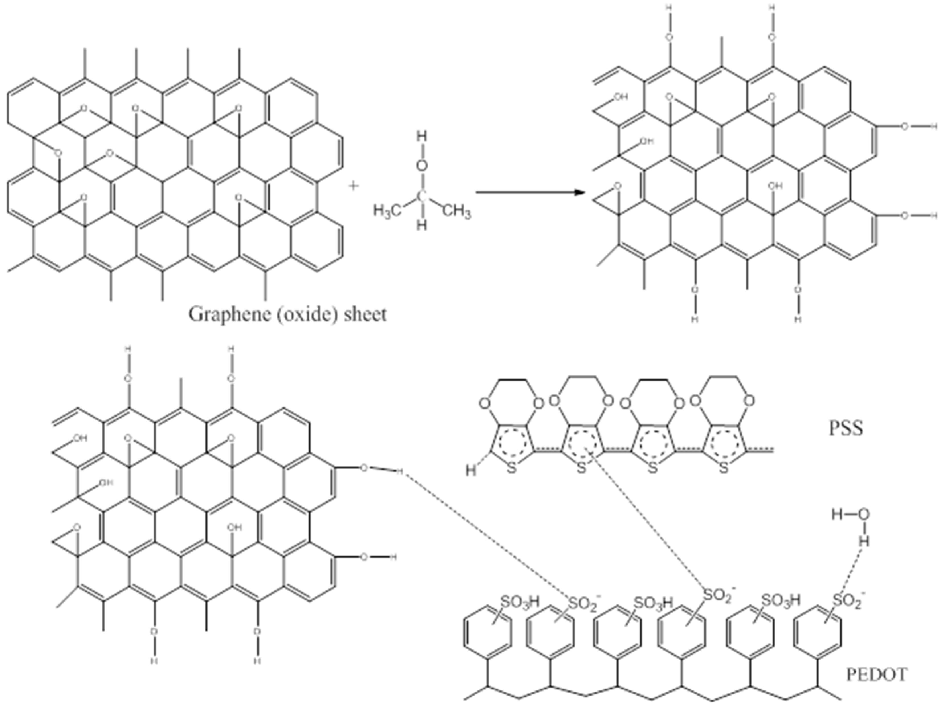
2.2. Poly(Ethylene-3,4-Dioxythiophene) (PEDOT) and Poly (Styrene Sulfonic Acid) (PSS)
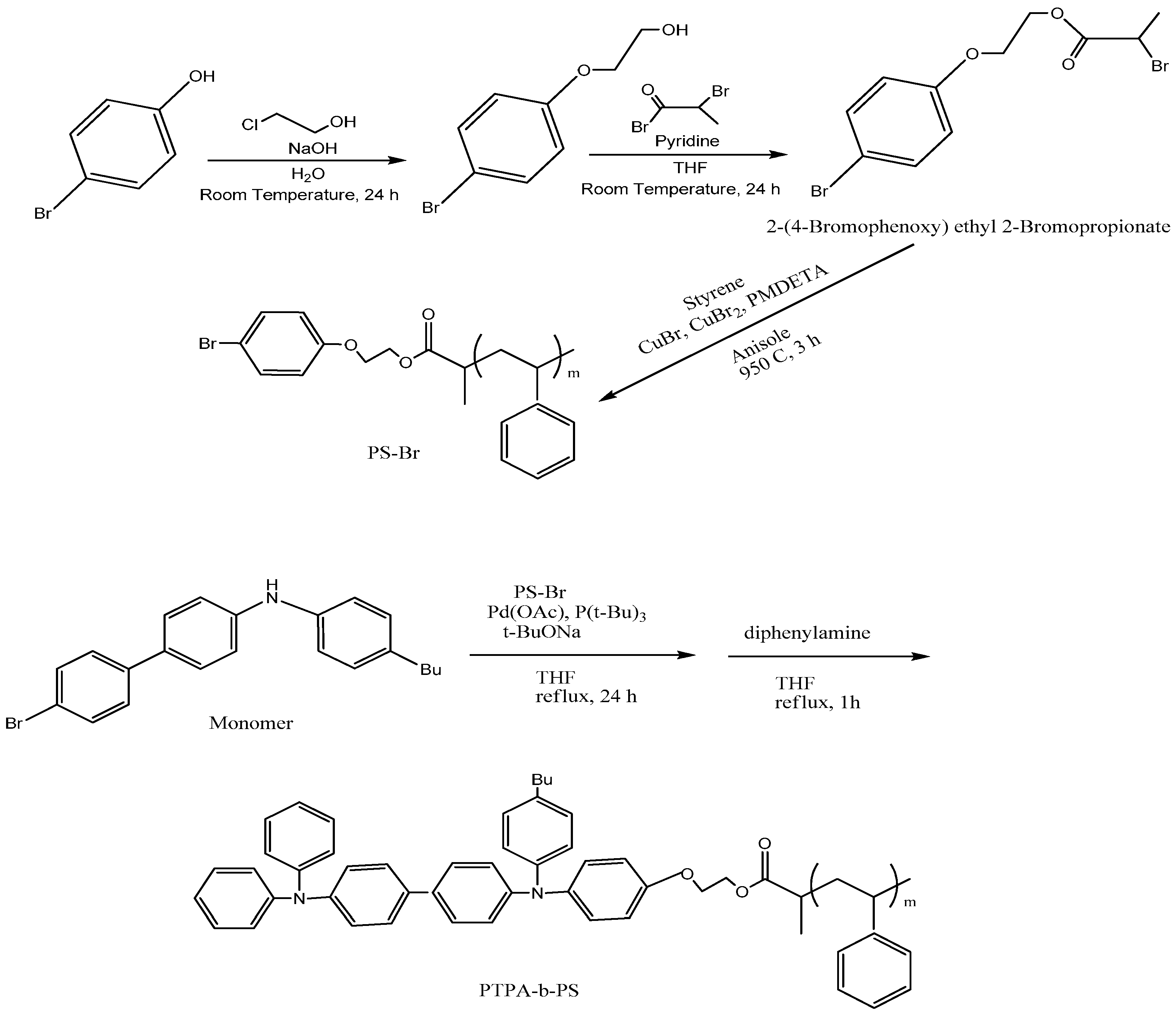
2.3. Poly(4-Butyltripheneylamine) (PTPA) and Polystyrene (PS)
2.4. Poly[2-Methoxy-5-(30,70-Dimethyloctyloxy)-1,4-Phenylenevinylene] (MDMO-PPV) and Lead (II) Sulfide (PbS)
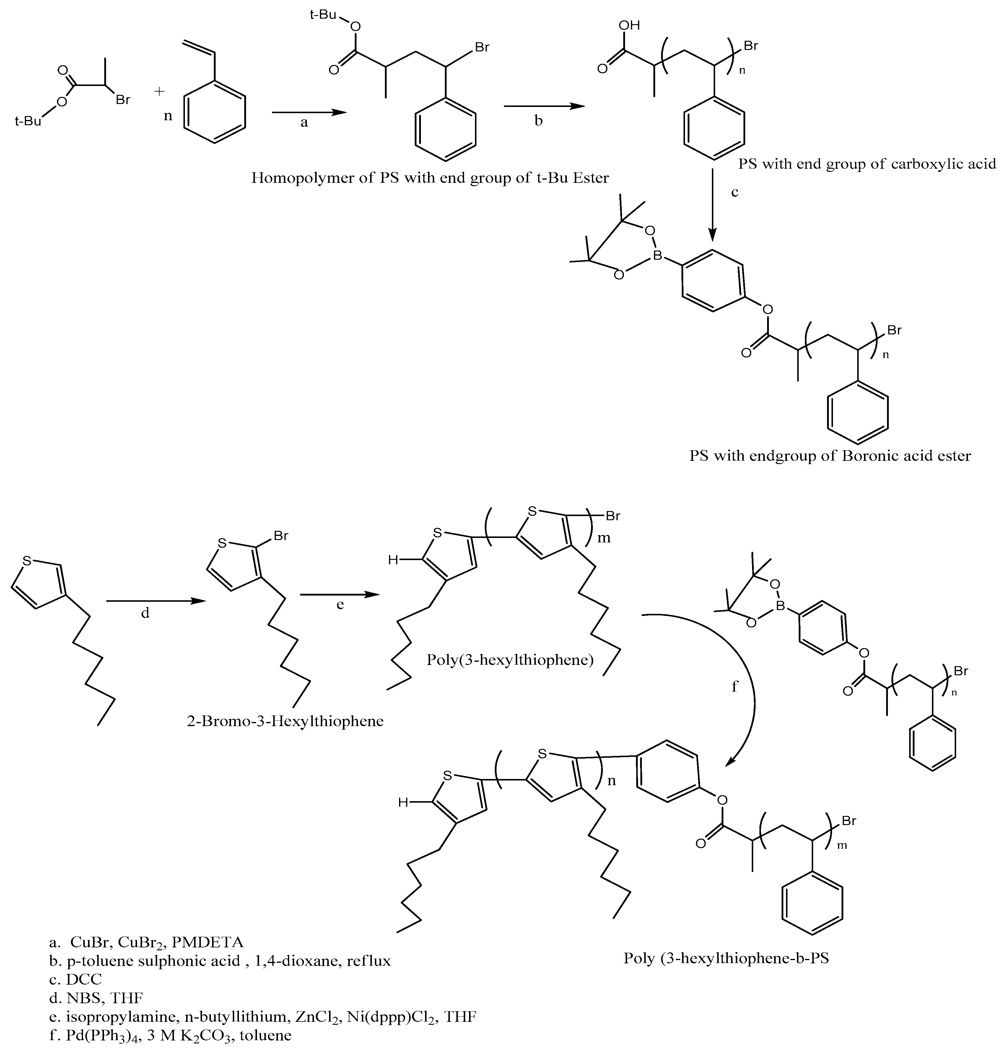
2.5. Poly (3-Hexyl Thiophene) (P3HT) and Polystyrene (PS)
3. Solar Energy Conversion Technology
3.1. Energy Generation Principle
3.1.1. Solar Radiation
3.1.2. Light Harvesting
3.1.3. Efficiency of Charge Transportation and Collection
3.2. Electric Generation Through Organic Solar Cells
3.2.1. Types of Solar Cells
- First Generation: Single (p-n) junction mono or multi crystalline silicon solar cells, the mono crystalline solar cell has an efficiency record of 25% [184].
- Second Generation: Thin films is currently composed of copper indium gallium selenide [179]. This type of cell has achieved efficiency of 20.4% on flexible polymer substrate [184,185]. Low manufacture cost and high efficiency, may lead this type of cell to have a great share in the solar cell market [74].
- Third Generation: Organic solar cells , Dye Sensitized Solar Cells and multijunction cells [109]. The and have the following maximums of efficiency recorded 12% [186] and 11.3% [187] respectively. On the other hand multijunction cells focus on increasing power respect cost ratio, by maximizing the solar spectrum they can capture [182].
3.2.2. Organic Solar Cells
- Wide range of very cheap materials and structures.
- High absorption coefficient.
- Ease of processing
- Mechanical Flexibility.
- Non-toxic.
- Adjustable band-gap.
- Control over the electric conductivity.
- They can be applied at room temperature.
- Low energy payback time: The energy payback time is the amount of time required for the solar cell, to generate the amount of energy use in its manufacture [193]. This is a life cycle metric that achieves 1% efficiency at short-term (life time of 2 years), 10% efficiency at midterm (life time of 10 years) and 15% efficiency in long-term (life time of 20 years) [194]. In this aspect have a better performance [194].
- Greenhouse gas emission: The greenhouse gas emission of the solar cell reflects the impact of this in the global climate [188]. In the current scenario, this value is higher in , that in comparison to other types of solar cells [188]. In the other hand for the long term scenario this changes drastically, where become the lesser emmiters of , due to increase of conversion efficiency and operating lifetime [188].
- Power conversion efficiency: To increase the efficiency a wider spectral absorption range is required, this has exceed 9% single junction [195,196,197] and 11% for tandem-junction solar cells [198]. In single-junction the film thickness of the photoactive layer is minimized to prevent recombination losses [188]. Theoretically the power conversion efficiency can be reduced to 25.5% by minimizing the loss of non-radiative voltage in fullerene-based organic solar cell [199].
- Tandem architectures.
- Plasmonics.
- Improvement upon the short diffusion length of excitons.
- Polymeric nano-composites including graphitic nano-structural material.
- Donor-Acceptor interface improving the number of excitons.
- Crystal structure improvements to increase the electrical conductivity.
- Maximizing the number of photogenerated carriers.
- Macromolecule dyes.
- Dendrimers.
- Pigments.
- Oligomers.
- Polymers.
- Small molecules.
- Others.
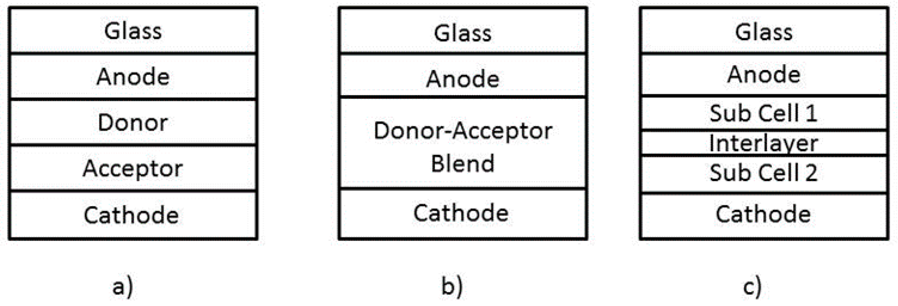
- Single layer: A solar cell composed of a single active material [179], usually requires a Schottky barrier in one of its contacts to allow the separations of photo excitations at the barrier field.
- Multiple layer or Hetero junction: A solar cell composed of multiple layers with different materials, some of this materials have low ionization potential and act as Donors, while some of this materials have a high electron affinity (EA/HUMO) and act as Acceptors [201,202]. This can be classified according to Figure 8:
- (a)
- Bilayer heterojunction (Planar heterojunction): Made of two layers, donor and acceptor between two electrodes [179].
- (b)
- (c)
- Tandem heterojunction: This type of solar cell has a two sub cells that complement the solar spectrum absorption, this sub cells are separated by an interlayer, which collects the holes and electrons generated by the cells [179]. Each sub cell is created to cover a specific region of the solar spectrum [203]. A great disadvantage for the single junction solar cells is photo-voltage loss, due the thermalization of hot carriers [206]. The organic tandem solar cell does not have these limitations, because of the Van de Waals bonding’s, this leads to a low cost and high efficiency [179].
3.3. Working Principle of Organic Solar Cells
Principle of Electrical Generation through Solar Cells
- Short circuit current : The current flowing in an illuminated solar cell, with no external resistance connected, this is the maximum amount of current the solar cell can achieve [179].
- Maximum power point : Is the magnitude of voltage and current , which yields the maximum power in the solar cell [179].
- Fill factor : is the ratio of generated power respect the maximum power it could produce [179].
- Power conversion efficiency : This magnitude reflects the electric power provided respect the total power irradiated to the surface of the solar cell [106].
- Quantum efficiency : Represents the efficiency in function the incident radiation wavelength [179].
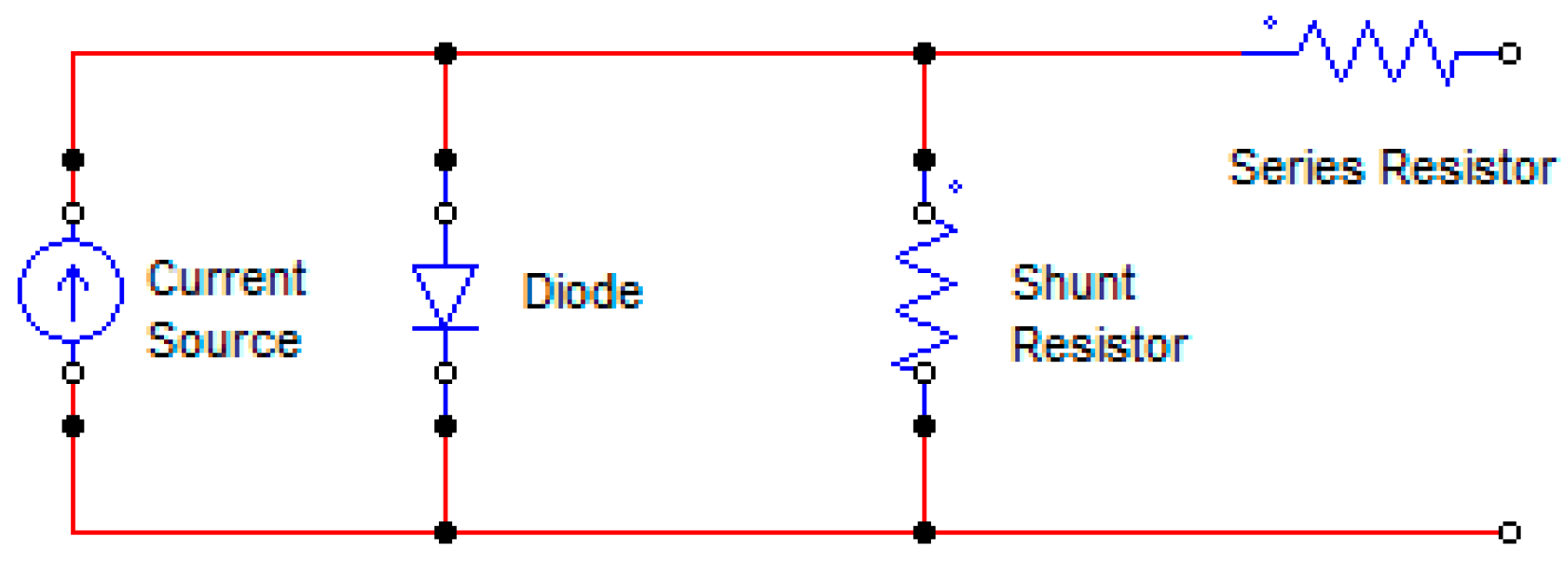
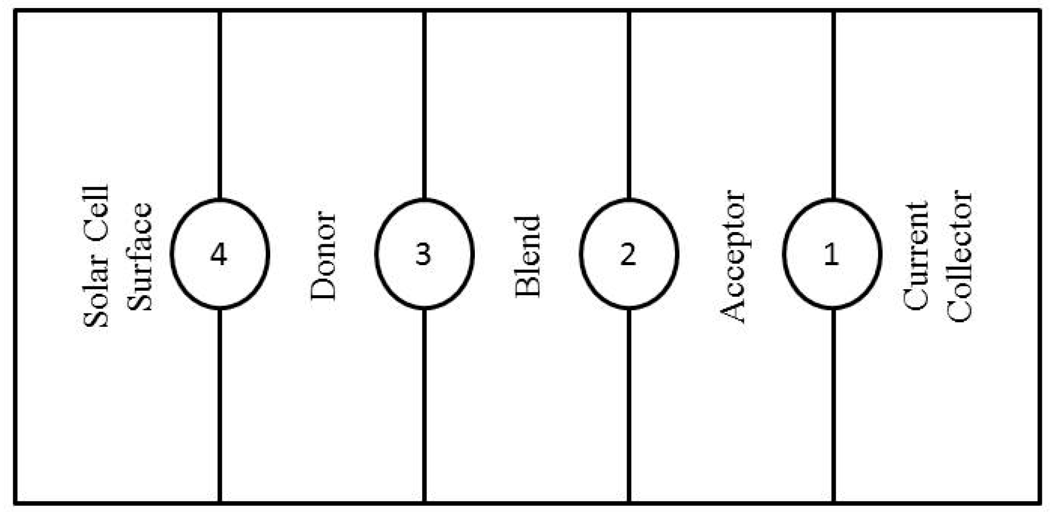
3.4. Mathematical Analysis of the Electric Generation Phenomena
- and : Hole and excitons fluxes in the donor layer.
- and : Electron and hole fluxes in the blend layer.
- : Electron in the acceptor layer.
- : Exciton generation rate in the donor layer.
- , and : respectively, concentration of electrons, excitons, and holes.
- : Exciton lifetime.
- , and : respectively, electrical potential in the acceptor, blend, and donor layer.
- : elemental charge.
- : Permitivity of the free space.
- and : respectively, permittivity of the acceptor and donor.
- : Dielectric constant of the blend layer.
- : Net charge generation rate.
- : Effective density of states for electrons and holes.
- : Built-in voltage of the cell.
- : Boltzman constant.
- : Temperature.
4. Application of Organic Polymer Solar Cell
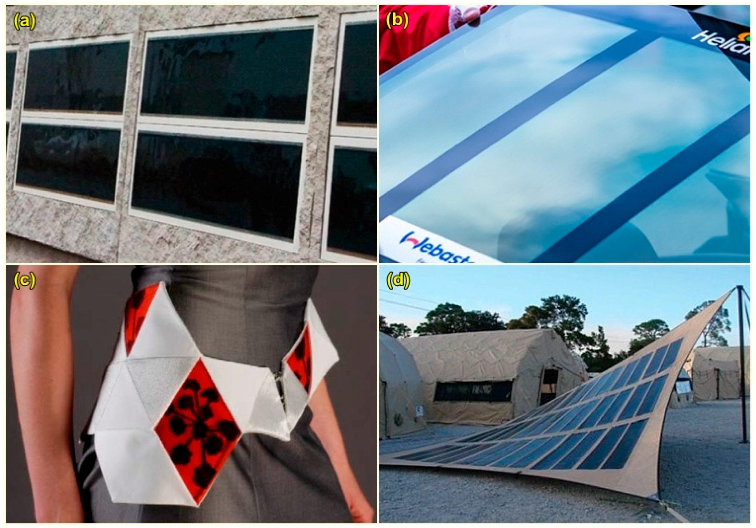
4.1. Building Integration
4.2. Integration on Cars
4.3. Garments, Textiles and Fabric Materials
4.4. Consumer Electronics
5. Conclusions
Acknowledgments
Author Contributions
Conflicts of Interest
References
- Hermann, W.A. Quantifying global exergy resources. Energy 2006, 31, 1685–1702. [Google Scholar] [CrossRef]
- IEA. World Energy Outlook 2004; IEA: Paris, France, 2004. [Google Scholar]
- Ismail, A.M.; Ramirez-Iniguez, R.; Asif, M.; Munir, A.B.; Muhammad-Sukki, F. Progress of solar photovoltaic in ASEAN countries: A review. Renew. Sustain. Energy Rev. 2015, 48, 399–412. [Google Scholar] [CrossRef]
- Sunwater Solar. What is Solar Thermal? Available online: http://sunwatersolar.com/solar-thermal/what-is-solar-thermal (accessed on 16 November 2017).
- Ciamician, G. The photochemistry of the future. Science 1912, 36, 385–394. [Google Scholar] [CrossRef] [PubMed]
- Spanggaard, H.; Krebs, F.C. A brief history of the development of organic and polymeric photovoltaics. Sol. Energy Mater. Sol. Cells 2004, 83, 125–146. [Google Scholar] [CrossRef]
- Reber, S.; Zimmermann, W.; Kieliba, T. Zone melting recrystallization of silicon films for crystalline silicon thin-film solar cells. Sol. Energy Mater. Sol. Cells 2001, 65, 409–416. [Google Scholar] [CrossRef]
- Green, M.A. Crystalline and thin-film silicon solar cells: State of the art and future potential. Sol. Energy 2003, 74, 181–192. [Google Scholar] [CrossRef]
- Zhao, J. Recent advances of high-efficiency single crystalline silicon solar cells in processing technologies and substrate materials. Sol. Energy Mater. Sol. Cells 2004, 82, 53–64. [Google Scholar] [CrossRef]
- Hashmi, S.G.; Halme, J.; Ma, Y.; Saukkonen, T.; Lund, P. A single-walled carbon nanotube coated flexible PVC counter electrode for dye-sensitized solar cells. Adv. Mater. Interfaces 2014, 1, 1300055. [Google Scholar] [CrossRef]
- McConnell, R. Assessment of the dye-sensitized solar cell. Renew. Sustain. Energy Rev. 2002, 6, 271–293. [Google Scholar] [CrossRef]
- Grätzel, M. Dye-sensitized solar cells. J. Photochem. Photobiol. C Photochem. Rev. 2003, 4, 145–153. [Google Scholar] [CrossRef]
- Anandan, S. Recent improvements and arising challenges in dye-sensitized solar cells. Sol. Energy Mater. Sol. Cells 2007, 91, 843–846. [Google Scholar] [CrossRef]
- Ackermann, J.; Videlot, C.; El Kassmi, A. Growth of organic semiconductors for hybrid solar cell application. Thin Solid Films 2002, 403–404, 157–161. [Google Scholar] [CrossRef]
- Arici, E.; Hoppe, H.; Schäffler, F.; Meissner, D.; Malik, M.A.; Sariciftci, N.S. Hybrid solar cells based on inorganic nanoclusters and conjugated polymers. Thin Solid Films 2004, 451–452, 612–618. [Google Scholar] [CrossRef]
- Wada, T.; Hashimoto, Y.; Nishiwaki, S.; Satoh, T.; Hayashi, S.; Negami, T.; Miyake, H. High-efficiency CIGS solar cells with modified CIGS surface. Sol. Energy Mater. Sol. Cells 2001, 67, 305–310. [Google Scholar] [CrossRef]
- Kessler, F.; Rudmann, D. Technological aspects of flexible CIGS solar cells and modules. Sol. Energy 2004, 77, 685–695. [Google Scholar] [CrossRef]
- Xakalashe, B.S.; Tangstad, M. Silicon processing from quartz to crystalline silicon solar cells. In Southern African Pyromethallurgy 2011; Jones, R.T., den Hoed, P., Eds.; Southern African Institute of Mining and Metallurgy: Johannesburg, South Africa, 2011; pp. 1–18. [Google Scholar]
- Krebs, F.C. Roll-to-roll fabrication of monolithic large-area polymer solar cells free from indium-tin-oxide. Sol. Energy Mater. Sol. Cells 2009, 93, 1636–1641. [Google Scholar] [CrossRef]
- Galagan, Y.; de Vries, I.G.; Langen, A.P.; Andriessen, R.; Verhees, W.J.H.; Veenstra, S.C.; Kroon, J.M. Technology development for roll-to-roll production of organic photovoltaics. Chem. Eng. Process. Process Intensif. 2011, 50, 454–461. [Google Scholar] [CrossRef]
- Krebs, F.C. Fabrication and processing of polymer solar cells: A review of printing and coating techniques. Sol. Energy Mater. Sol. Cells 2009, 93, 394–412. [Google Scholar] [CrossRef]
- Krebs, F.C. Polymer solar cell modules prepared using roll-to-roll methods: Knife-over-edge coating, slot-die coating and screen printing. Sol. Energy Mater. Sol. Cells 2009, 93, 465–475. [Google Scholar] [CrossRef]
- Blankenburg, L.; Schultheis, K.; Schache, H.; Sensfuss, S.; Schrödner, M. Reel-to-reel wet coating as an efficient up-scaling technique for the production of bulk-heterojunction polymer solar cells. Sol. Energy Mater. Sol. Cells 2009, 93, 476–483. [Google Scholar] [CrossRef]
- Medford, A.J.; Lilliedal, M.R.; Jørgensen, M.; Aarø, D.; Pakalski, H.; Fyenbo, J.; Krebs, F.C. Grid-connected polymer solar panels: Initial considerations of cost, lifetime, and practicality. Opt. Express 2010, 18 (Suppl. 3), A272–A285. [Google Scholar] [CrossRef] [PubMed]
- Amb, C.M.; Chen, S.; Graham, K.R.; Subbiah, J.; Small, C.E.; So, F.; Reynolds, J.R. Dithienogermole as a fused electron donor in bulk heterojunction solar cells. J. Am. Chem. Soc. 2011, 133, 10062–10065. [Google Scholar] [CrossRef] [PubMed]
- Service, R.F. Outlook brightens for plastic solar cells. Science 2011, 332, 293. [Google Scholar] [CrossRef] [PubMed]
- Li, G.; Zhu, R.; Yang, Y. Polymer solar cells. Nat. Photonics 2012, 6, 153–161. [Google Scholar] [CrossRef]
- Sun, S.-S.; O’Neill, H. Sunlight Energy Conversion Via Organics. In Handbook of Photovoltaic Science and Engineering; Luque, A., Hegedus, S., Eds.; John Wiley & Sons, Ltd.: Chichester, UK, 2011; pp. 675–715. ISBN 9780470974704. [Google Scholar]
- Sariciftci, N.S.; Sun, S.-S. Organic Photovoltaics: Mechanism, Materials, and Devices; Taylor & Francis: Boca Raton, FL, USA, 2005; ISBN 1420026356. [Google Scholar]
- Krebs, F.C. Polymer Photovoltaics: A Practical Approach; SPIE Press: Washington, DC, USA, 2008; ISBN 9780819467812. [Google Scholar]
- Günes, S.; Neugebauer, H.; Sariciftci, N.S. Conjugated Polymer-Based Organic Solar Cells. Chem. Rev. 2007, 107, 1324–1338. [Google Scholar] [CrossRef] [PubMed]
- Skotheim, T.A.; Reynolds, J.R. Handbook of Conducting Polymers; CRC Press: Boca Raton, FL, USA, 2007; ISBN 9781574446654. [Google Scholar]
- Krebs, F.C.; Tromholt, T.; Jørgensen, M. Upscaling of polymer solar cell fabrication using full roll-to-roll processing. Nanoscale 2010, 2, 873. [Google Scholar] [CrossRef] [PubMed]
- Zhou, Y.; Li, F.; Barrau, S.; Tian, W.; Inganäs, O.; Zhang, F. Inverted and transparent polymer solar cells prepared with vacuum-free processing. Sol. Energy Mater. Sol. Cells 2009, 93, 497–500. [Google Scholar] [CrossRef]
- Hau, S.K.; Yip, H.-L.; Zou, J.; Jen, A.K.-Y. Indium tin oxide-free semi-transparent inverted polymer solar cells using conducting polymer as both bottom and top electrodes. Org. Electron. 2009, 10, 1401–1407. [Google Scholar] [CrossRef]
- Winther-Jensen, B.; Krebs, F.C. High-conductivity large-area semi-transparent electrodes for polymer photovoltaics by silk screen printing and vapour-phase deposition. Sol. Energy Mater. Sol. Cells 2006, 90, 123–132. [Google Scholar] [CrossRef]
- Ahlswede, E.; Mühleisen, W.; bin Moh Wahi, M.W.; Hanisch, J.; Powalla, M. Highly efficient organic solar cells with printable low-cost transparent contacts. Appl. Phys. Lett. 2008, 92, 143307. [Google Scholar] [CrossRef]
- Chang, Y.-M.; Wang, L.; Su, W.-F. Polymer solar cells with poly(3,4-ethylenedioxythiophene) as transparent anode. Org. Electron. 2008, 9, 968–973. [Google Scholar] [CrossRef]
- Glatthaar, M.; Niggemann, M.; Zimmermann, B.; Lewer, P.; Riede, M.; Hinsch, A.; Luther, J. Organic solar cells using inverted layer sequence. Thin Solid Films 2005, 491, 298–300. [Google Scholar] [CrossRef]
- Zimmermann, B.; Glatthaar, M.; Niggemann, M.; Riede, M.K.; Hinsch, A.; Gombert, A. ITO-free wrap through organic solar cells—A module concept for cost-efficient reel-to-reel production. Sol. Energy Mater. Sol. Cells 2007, 91, 374–378. [Google Scholar] [CrossRef]
- Tvingstedt, K.; Inganäs, O. Electrode grids for ITO free organic photovoltaic devices. Adv. Mater. 2007, 19, 2893–2897. [Google Scholar] [CrossRef]
- Zou, J.; Yip, H.-L.; Hau, S.K.; Jen, A.K.-Y. Metal grid/conducting polymer hybrid transparent electrode for inverted polymer solar cells. Appl. Phys. Lett. 2010, 96, 203301. [Google Scholar] [CrossRef]
- Aernouts, T.; Vanlaeke, P.; Geens, W.; Poortmans, J.; Heremans, P.; Borghs, S.; Mertens, R.; Andriessen, R.; Leenders, L. Printable anodes for flexible organic solar cell modules. Thin Solid Films 2004, 451–452, 22–25. [Google Scholar] [CrossRef]
- Kazmerski, L.L. Solar photovoltaics R&D at the tipping point: A 2005 technology overview. J. Electron Spectrosc. Relat. Phenomena 2006, 150, 105–135. [Google Scholar] [CrossRef]
- Luque, A.; Hegedus, S. Handbook of Photovoltaic Science and Engineering, 2nd ed.; John Wiley and Sons, Ltd.: New York, NY, USA, 2010. [Google Scholar]
- Green, M.A. Third Generation Photovoltaics: Advanced Solar Energy Conversion; Springer: Berlin, Germany, 2006; ISBN 9783540265634. [Google Scholar]
- Ma, W.; Yang, C.; Gong, X.; Lee, K.; Heeger, A.J. Thermally stable, efficient polymer solar cells with nanoscale control of the interpenetrating network morphology. Adv. Funct. Mater. 2005, 15, 1617–1622. [Google Scholar] [CrossRef]
- Li, G.; Shrotriya, V.; Huang, J.; Yao, Y.; Moriarty, T.; Emery, K.; Yang, Y. High-efficiency solution processable polymer photovoltaic cells by self-organization of polymer blends. Nat. Mater. 2005, 4, 864–868. [Google Scholar] [CrossRef]
- Reyes-Reyes, M.; Kim, K.; Dewald, J.; López-Sandoval, R.; Avadhanula, A.; Curran, S.; Carroll, D.L. Meso-structure formation for enhanced organic photovoltaic cells. Org. Lett. 2005, 7, 5749–5752. [Google Scholar] [CrossRef] [PubMed]
- Kim, J.Y.; Kim, S.H.; Lee, H.-H.; Lee, K.; Ma, W.; Gong, X.; Heeger, A.J. New architecture for high-efficiency polymer photovoltaic cells using solution-based titanium oxide as an optical spacer. Adv. Mater. 2006, 18, 572–576. [Google Scholar] [CrossRef]
- Peet, J.; Kim, J.Y.; Coates, N.E.; Ma, W.L.; Moses, D.; Heeger, A.J.; Bazan, G.C. Efficiency enhancement in low-bandgap polymer solar cells by processing with alkane dithiols. Nat. Mater. 2007, 6, 497–500. [Google Scholar] [CrossRef] [PubMed]
- Hill, I.G.; Kahn, A.; Soos, Z.G.; Pascal, R.A., Jr. Charge-separation energy in films of π-conjugated organic molecules. Chem. Phys. Lett. 2000, 327, 181–188. [Google Scholar] [CrossRef]
- Alvarado, S.; Seidler, P.; Lidzey, D.; Bradley, D. Direct determination of the exciton binding energy of conjugated polymers using a scanning tunneling microscope. Phys. Rev. Lett. 1998, 81, 1082–1085. [Google Scholar] [CrossRef]
- Kersting, R.; Lemmer, U.; Deussen, M.; Bakker, H.J.; Mahrt, R.F.; Kurz, H.; Arkhipov, V.I.; Bässler, H.; Göbel, E.O. Ultrafast field-induced dissociation of excitons in conjugated polymers. Phys. Rev. Lett. 1994, 73, 1440–1443. [Google Scholar] [CrossRef] [PubMed]
- Tang, C.W. Two-layer organic photovoltaic cell. Appl. Phys. Lett. 1986, 48, 183–185. [Google Scholar] [CrossRef]
- Barker, J.A.; Ramsdale, C.M.; Greenham, N.C. Modeling the current-voltage characteristics of bilayer polymer photovoltaic devices. Phys. Rev. B 2003, 67, 75205. [Google Scholar] [CrossRef]
- Morteani, A.C.; Sreearunothai, P.; Herz, L.M.; Friend, R.H.; Silva, C. Exciton regeneration at polymeric semiconductor heterojunctions. Phys. Rev. Lett. 2004, 92, 247402. [Google Scholar] [CrossRef] [PubMed]
- Offermans, T.; Meskers, S.C.J.; Janssen, R.A.J. Monte-Carlo simulations of geminate electron–hole pair dissociation in a molecular heterojunction: A two-step dissociation mechanism. Chem. Phys. 2005, 308, 125–133. [Google Scholar] [CrossRef]
- Peumans, P.; Forrest, S.R. Separation of geminate charge-pairs at donor–acceptor interfaces in disordered solids. Chem. Phys. Lett. 2004, 398, 27–31. [Google Scholar] [CrossRef]
- Mihailetchi, V.D.; Koster, L.J.A.; Hummelen, J.C.; Blom, P.W.M. Photocurrent generation in polymer-fullerene bulk heterojunctions. Phys. Rev. Lett. 2004, 93, 216601. [Google Scholar] [CrossRef] [PubMed]
- Sariciftci, N.S.; Smilowitz, L.; Heeger, A.J.; Wudl, F.; Heeger, A.J. Photoinduced electron transfer from a conducting polymer to buckminsterfullerene. Science 1992, 258, 1474–1476. [Google Scholar] [CrossRef] [PubMed]
- Yu, G.; Gao, J.; Hummelen, J.C.; Wudl, F.; Heeger, A.J. Polymer Photovoltaic Cells: Enhanced Efficiencies via a Network of Internal Donor-Acceptor Heterojunctions. Science 1995, 270, 1789–1791. [Google Scholar] [CrossRef]
- Shaheen, S.E.; Brabec, C.J.; Sariciftci, N.S.; Padinger, F.; Fromherz, T.; Hummelen, J.C. 2.5% efficient organic plastic solar cells. Appl. Phys. Lett. 2001, 78, 841–843. [Google Scholar] [CrossRef]
- Brabec, C.J.; Shaheen, S.E.; Winder, C.; Sariciftci, N.S.; Denk, P. Effect of LiF/metal electrodes on the performance of plastic solar cells. Appl. Phys. Lett. 2002, 80, 1288–1290. [Google Scholar] [CrossRef]
- Shaheen, S.E.; Vangeneugden, D.; Kiebooms, R.; Vanderzande, D.; Fromherz, T.; Padinger, F.; Brabec, C.J.; Sariciftci, N.S. Low band-gap polymeric photovoltaic devices. Synth. Met. 2001, 121, 1583–1584. [Google Scholar] [CrossRef]
- Svensson, M.; Zhang, F.; Veenstra, S.C.; Verhees, W.J.H.; Hummelen, J.C.; Kroon, J.M.; Inganäs, O.; Andersson, M.R. High-performance polymer solar cells of an alternating polyfluorene copolymer and a fullerene derivative. Adv. Mater. 2003, 15, 988–991. [Google Scholar] [CrossRef]
- Mühlbacher, D.; Scharber, M.; Morana, M.; Zhu, Z.; Waller, D.; Gaudiana, R.; Brabec, C. High photovoltaic performance of a low-bandgap polymer. Adv. Mater. 2006, 18, 2884–2889. [Google Scholar] [CrossRef]
- Schilinsky, P.; Waldauf, C.; Brabec, C.J. Recombination and loss analysis in polythiophene based bulk heterojunction photodetectors. Appl. Phys. Lett. 2002, 81, 3885–3887. [Google Scholar] [CrossRef]
- Padinger, F.; Rittberger, R.S.; Sariciftci, N.S. Effects of postproduction treatment on plastic solar cells. Adv. Funct. Mater. 2003, 13, 85–88. [Google Scholar] [CrossRef]
- Zhao, J.; Li, Y.; Yang, G.; Jiang, K.; Lin, H.; Ade, H.; Ma, W.; Yan, H. Efficient organic solar cells processed from hydrocarbon solvents. Nat. Energy 2016, 1, 15027. [Google Scholar] [CrossRef]
- Halls, J.J.M.; Walsh, C.A.; Greenham, N.C.; Marseglia, E.A.; Friend, R.H.; Moratti, S.C.; Holmes, A.B. Efficient photodiodes from interpenetrating polymer networks. Nature 1995, 376, 498–500. [Google Scholar] [CrossRef]
- Koetse, M.M.; Sweelssen, J.; Hoekerd, K.T.; Schoo, H.F.M.; Veenstra, S.C.; Kroon, J.M.; Yang, X.; Loos, J. Efficient polymer: Polymer bulk heterojunction solar cells. Appl. Phys. Lett. 2006, 88, 83504. [Google Scholar] [CrossRef]
- Veenstra, S.C.; Verhees, W.J.H.; Kroon, J.M.; Koetse, M.M.; Sweelssen, J.; Bastiaansen, J.J.A.M.; Schoo, H.F.M.; Yang, X.; Alexeev, A.; Loos, J.; et al. Photovoltaic properties of a conjugated polymer blend of MDMO−PPV and PCNEPV. Chem. Mater. 2004, 16, 2503–2508. [Google Scholar] [CrossRef]
- McNeill, C.R.; Abrusci, A.; Zaumseil, J.; Wilson, R.; McKiernan, M.J.; Burroughes, J.H.; Halls, J.J.M.; Greenham, N.C.; Friend, R.H. Dual electron donor/electron acceptor character of a conjugated polymer in efficient photovoltaic diodes. Appl. Phys. Lett. 2007, 90, 193506. [Google Scholar] [CrossRef]
- Ye, L.; Hu, H.; Ghasemi, M.; Wang, T.; Collins, B.A.; Kim, J.-H.; Jiang, K.; Carpenter, J.H.; Li, H.; Li, Z.; et al. Quantitative relations between interaction parameter, miscibility and function in organic solar cells. Nat. Mater. 2018, 17, 253–260. [Google Scholar] [CrossRef] [PubMed]
- Ye, L.; Zhao, W.; Li, S.; Mukherjee, S.; Carpenter, J.H.; Awartani, O.; Jiao, X.; Hou, J.; Ade, H. High-Efficiency Nonfullerene Organic Solar Cells: Critical Factors that Affect Complex Multi-Length Scale Morphology and Device Performance. Adv. Energy Mater. 2017, 7, 1602000. [Google Scholar] [CrossRef]
- Ye, L.; Xiong, Y.; Zhang, Q.; Li, S.; Wang, C.; Jiang, Z.; Hou, J.; You, W.; Ade, H. Surpassing 10% Efficiency Benchmark for Nonfullerene Organic Solar Cells by Scalable Coating in Air from Single Nonhalogenated Solvent. Adv. Mater. 2018, 30, 1705485. [Google Scholar] [CrossRef] [PubMed]
- Martens, T.; D’Haen, J.; Munters, T.; Beelen, Z.; Goris, L.; Manca, J.; D’Olieslaeger, M.; Vanderzande, D.; De Schepper, L.; Andriessen, R. Disclosure of the nanostructure of MDMO-PPV: PCBM bulk hetero-junction organic solar cells by a combination of SPM and TEM. Synth. Met. 2003, 138, 243–247. [Google Scholar] [CrossRef]
- Hoppe, H.; Niggemann, M.; Winder, C.; Kraut, J.; Hiesgen, R.; Hinsch, A.; Meissner, D.; Sariciftci, N.S. Nanoscale morphology of conjugated polymer/fullerene-based bulk- heterojunction solar cells. Adv. Funct. Mater. 2004, 14, 1005–1011. [Google Scholar] [CrossRef]
- Grätzel, M.; Bach, U.; Lupo, D.; Comte, P.; Moser, J.E.; Weissörtel, F.; Salbeck, J.; Spreitzer, H. Solid-state dye-sensitized mesoporous TiO2 solar cells with high photon-to-electron conversion efficiencies. Nature 1998, 395, 583–585. [Google Scholar] [CrossRef]
- O’Regan, B.; Grätzel, M. A low-cost, high-efficiency solar cell based on dye-sensitized colloidal TiO2 films. Nature 1991, 353, 737–740. [Google Scholar] [CrossRef]
- Ravirajan, P.; Peiró, A.M.; Nazeeruddin, M.K.; Graetzel, M.; Bradley, D.D.C.; James, R.D.; Nelson, J. Hybrid polymer/zinc oxide photovoltaic devices with vertically oriented ZnO nanorods and an amphiphilic molecular interface layer. J. Phys. Chem. B 2006, 110, 7635–7639. [Google Scholar] [CrossRef] [PubMed]
- Goh, C.; Scully, S.R.; McGehee, M.D. Effects of molecular interface modification in hybrid organic-inorganic photovoltaic cells. J. Appl. Phys. 2007, 101, 114503. [Google Scholar] [CrossRef]
- Zhao, X.; Wang, M. Organic hole-transporting materials for efficient perovskite solar cells. Mater. Today Energy 2017. [Google Scholar] [CrossRef]
- Bin, H.; Zhang, Z.-G.; Gao, L.; Chen, S.; Zhong, L.; Xue, L.; Yang, C.; Li, Y. Non-Fullerene Polymer Solar Cells Based on Alkylthio and Fluorine Substituted 2D-Conjugated Polymers Reach 9.5% Efficiency. J. Am. Chem. Soc. 2016, 138, 4657–4664. [Google Scholar] [CrossRef] [PubMed]
- Yan, C.; Barlow, S.; Wang, Z.; Yan, H.; Jen, A.K.-Y.; Marder, S.R.; Zhan, X. Non-fullerene acceptors for organic solar cells. Nat. Rev. Mater. 2018, 3, 18003. [Google Scholar] [CrossRef]
- Hou, J.; Inganäs, O.; Friend, R.H.; Gao, F. Organic solar cells based on non-fullerene acceptors. Nat. Mater. 2018, 17, 119–128. [Google Scholar] [CrossRef] [PubMed]
- Zhu, J.; Ke, Z.; Zhang, Q.; Wang, J.; Dai, S.; Wu, Y.; Xu, Y.; Lin, Y.; Ma, W.; You, W.; et al. Naphthodithiophene-Based Nonfullerene Acceptor for High-Performance Organic Photovoltaics: Effect of Extended Conjugation. Adv. Mater. 2018, 30, 1704713. [Google Scholar] [CrossRef] [PubMed]
- Zhao, W.; Li, S.; Yao, H.; Zhang, S.; Zhang, Y.; Yang, B.; Hou, J. Molecular Optimization Enables over 13% Efficiency in Organic Solar Cells. J. Am. Chem. Soc. 2017, 139, 7148–7151. [Google Scholar] [CrossRef] [PubMed]
- Li, Z.; Jiang, K.; Yang, G.; Lai, J.Y.L.; Ma, T.; Zhao, J.; Ma, W.; Yan, H. Donor polymer design enables efficient non-fullerene organic solar cells. Nat. Commun. 2016, 7, 13094. [Google Scholar] [CrossRef] [PubMed]
- Zhang, M.; Gao, W.; Zhang, F.; Mi, Y.; Wang, W.; An, Q.; Wang, J.; Ma, X.; Miao, J.; Hu, Z.; et al. Efficient ternary non-fullerene polymer solar cells with PCE of 11.92% and FF of 76.5%. Energy Environ. Sci. 2018. [Google Scholar] [CrossRef]
- Guo, B.; Li, W.; Guo, X.; Meng, X.; Ma, W.; Zhang, M.; Li, Y. High Efficiency Nonfullerene Polymer Solar Cells with Thick Active Layer and Large Area. Adv. Mater. 2017, 29, 1702291. [Google Scholar] [CrossRef] [PubMed]
- Kumari, T.; Lee, S.M.; Kang, S.-H.; Chen, S.; Yang, C. Ternary solar cells with a mixed face-on and edge-on orientation enable an unprecedented efficiency of 12.1%. Energy Environ. Sci. 2017, 10, 258–265. [Google Scholar] [CrossRef]
- Kan, B.; Feng, H.; Wan, X.; Liu, F.; Ke, X.; Wang, Y.; Wang, Y.; Zhang, H.; Li, C.; Hou, J.; Chen, Y. Small-Molecule Acceptor Based on the Heptacyclic Benzodi(cyclopentadithiophene) Unit for Highly Efficient Nonfullerene Organic Solar Cells. J. Am. Chem. Soc. 2017, 139, 4929–4934. [Google Scholar] [CrossRef] [PubMed]
- Yang, Y.; Zhang, Z.-G.; Bin, H.; Chen, S.; Gao, L.; Xue, L.; Yang, C.; Li, Y. Side-Chain Isomerization on an n-type Organic Semiconductor ITIC Acceptor Makes 11.77% High Efficiency Polymer Solar Cells. J. Am. Chem. Soc. 2016, 138, 15011–15018. [Google Scholar] [CrossRef] [PubMed]
- Liu, F.; Zhou, Z.; Zhang, C.; Vergote, T.; Fan, H.; Liu, F.; Zhu, X. A Thieno[3,4-b]thiophene-Based Non-fullerene Electron Acceptor for High-Performance Bulk-Heterojunction Organic Solar Cells. J. Am. Chem. Soc. 2016, 138, 15523–15526. [Google Scholar] [CrossRef] [PubMed]
- Zhao, W.; Qian, D.; Zhang, S.; Li, S.; Inganäs, O.; Gao, F.; Hou, J. Fullerene-Free Polymer Solar Cells with over 11% Efficiency and Excellent Thermal Stability. Adv. Mater. 2016, 28, 4734–4739. [Google Scholar] [CrossRef] [PubMed]
- Li, S.; Ye, L.; Zhao, W.; Zhang, S.; Mukherjee, S.; Ade, H.; Hou, J. Energy-Level Modulation of Small-Molecule Electron Acceptors to Achieve over 12% Efficiency in Polymer Solar Cells. Adv. Mater. 2016, 28, 9423–9429. [Google Scholar] [CrossRef] [PubMed]
- Zhao, F.; Dai, S.; Wu, Y.; Zhang, Q.; Wang, J.; Jiang, L.; Ling, Q.; Wei, Z.; Ma, W.; You, W.; et al. Single-Junction Binary-Blend Nonfullerene Polymer Solar Cells with 12.1% Efficiency. Adv. Mater. 2017, 29, 1700144. [Google Scholar] [CrossRef] [PubMed]
- Wang, J.; Wang, W.; Wang, X.; Wu, Y.; Zhang, Q.; Yan, C.; Ma, W.; You, W.; Zhan, X. Enhancing Performance of Nonfullerene Acceptors via Side-Chain Conjugation Strategy. Adv. Mater. 2017, 29, 1702125. [Google Scholar] [CrossRef] [PubMed]
- Wang, W.; Yan, C.; Lau, T.-K.; Wang, J.; Liu, K.; Fan, Y.; Lu, X.; Zhan, X. Fused Hexacyclic Nonfullerene Acceptor with Strong Near-Infrared Absorption for Semitransparent Organic Solar Cells with 9.77% Efficiency. Adv. Mater. 2017, 29, 1701308. [Google Scholar] [CrossRef] [PubMed]
- Lin, Y.; Zhao, F.; Wu, Y.; Chen, K.; Xia, Y.; Li, G.; Prasad, S.K.K.; Zhu, J.; Huo, L.; Bin, H.; et al. Mapping Polymer Donors toward High-Efficiency Fullerene Free Organic Solar Cells. Adv. Mater. 2017, 29, 1604155. [Google Scholar] [CrossRef] [PubMed]
- Yao, H.; Cui, Y.; Yu, R.; Gao, B.; Zhang, H.; Hou, J. Design, Synthesis, and Photovoltaic Characterization of a Small Molecular Acceptor with an Ultra-Narrow Band Gap. Angew. Chem. Int. Ed. 2017, 56, 3045–3049. [Google Scholar] [CrossRef] [PubMed]
- Bin, H.; Gao, L.; Zhang, Z.-G.; Yang, Y.; Zhang, Y.; Zhang, C.; Chen, S.; Xue, L.; Yang, C.; Xiao, M.; et al. 11.4% Efficiency non-fullerene polymer solar cells with trialkylsilyl substituted 2D-conjugated polymer as donor. Nat. Commun. 2016, 7, 13651. [Google Scholar] [CrossRef] [PubMed]
- Huang, J.-H.; Lee, K.-C. Highly Stable, Solution-Processable Phenothiazine Derivative as Hole Collection Material for Organic Solar Cells. ACS Appl. Mater. Interfaces 2014, 6, 7680–7685. [Google Scholar] [CrossRef] [PubMed]
- Yoon, T.P.; Ischay, M.A.; Du, J. Visible light photocatalysis as a greener approach to photochemical synthesis. Nat. Chem. 2010, 2, 527–532. [Google Scholar] [CrossRef] [PubMed]
- Kumavat, P.P.; Sonar, P.; Dalal, D.S. An overview on basics of organic and dye sensitized solar cells, their mechanism and recent improvements. Renew. Sustain. Energy Rev. 2017, 78, 1262–1287. [Google Scholar] [CrossRef]
- Silvestri, F.; Marrocchi, A.; Seri, M.; Kim, C.; Marks, T.J.; Facchetti, A.; Taticchi, A. Solution-processable low-molecular weight extended arylacetylenes: Versatile p-type semiconductors for field-effect transistors and bulk heterojunction solar cells. J. Am. Chem. Soc. 2010, 132, 6108–6123. [Google Scholar] [CrossRef] [PubMed]
- Patel, H.; Agarwal, V. MPPT Scheme for a PV-Fed Single-Phase Single-Stage Grid-Connected Inverter Operating in CCM With Only One Current Sensor. IEEE Trans. Energy Convers. 2009, 24, 256–263. [Google Scholar] [CrossRef]
- Thounthong, P.; Chunkag, V.; Sethakul, P.; Sikkabut, S.; Pierfederici, S.; Davat, B. Energy management of fuel cell/solar cell/supercapacitor hybrid power source. J. Power Sources 2011, 196, 313–324. [Google Scholar] [CrossRef]
- Han, G.; Zhang, S.; Boix, P.P.; Wong, L.H.; Sun, L.; Lien, S.-Y. Towards high efficiency thin film solar cells. Prog. Mater. Sci. 2017, 87, 246–291. [Google Scholar] [CrossRef]
- Hagfeldt, A.; Boschloo, G.; Sun, L.; Kloo, L.; Pettersson, H. Dye-sensitized solar cells. Chem. Rev. 2010, 110, 6595–6663. [Google Scholar] [CrossRef] [PubMed]
- Sharifi, N.; Tajabadi, F.; Taghavinia, N. Recent developments in dye-sensitized solar cells. ChemPhysChem 2014, 15, 3902–3927. [Google Scholar] [CrossRef] [PubMed]
- Liu, X.-H.; Hou, L.-X.; Wang, J.-F.; Liu, B.; Yu, Z.-S.; Ma, L.-Q.; Yang, S.-P.; Fu, G.-S. Plasmonic-enhanced polymer solar cells with high efficiency by addition of silver nanoparticles of different sizes in different layers. Sol. Energy 2014, 110, 627–635. [Google Scholar] [CrossRef]
- Etxebarria, I.; Ajuria, J.; Pacios, R. Polymer:fullerene solar cells: Materials, processing issues, and cell layouts to reach power conversion efficiency over 10%, a review. J. Photonics Energy 2015, 5, 57214. [Google Scholar] [CrossRef]
- Kuendig, J.; Goetz, M.; Shah, A.; Gerlach, L.; Fernandez, E. Thin film silicon solar cells for space applications: Study of proton irradiation and thermal annealing effects on the characteristics of solar cells and individual layers. Sol. Energy Mater. Sol. Cells 2003, 79, 425–438. [Google Scholar] [CrossRef]
- Horiuchi, N.; Nozaki, T.; Chiba, A. Improvement in electrical performance of radiation-damaged silicon solar cells by annealing. Nucl. Instrum. Methods Phys. Res. Sect. A 2000, 443, 186–193. [Google Scholar] [CrossRef]
- Li, Y.-S.; Tsai, C.-H.; Kao, S.-H.; Wu, I.-W.; Chen, J.-Z.; Wu, C.-I.; Lin, C.-F.; Cheng, I.-C. Single-layer organic–inorganic-hybrid thin-film encapsulation for organic solar cells. J. Phys. D Appl. Phys. 2013, 46, 435502. [Google Scholar] [CrossRef]
- Jain, V.; Rajbongshi, B.K.; Tej Mallajosyula, A.; Bhattacharjya, G.; Kumar Iyer, S.S.; Ramanathan, G. Photovoltaic effect in single-layer organic solar cell devices fabricated with two new imidazolin-5-one molecules. Sol. Energy Mater. Sol. Cells 2008, 92, 1043–1046. [Google Scholar] [CrossRef]
- Chamberlain, G.A. Organic solar cells: A review. Sol. Cells 1983, 8, 47–83. [Google Scholar] [CrossRef]
- Wöhrle, D.; Meissner, D. Organic solar cells. Adv. Mater. 1991, 3, 129–138. [Google Scholar] [CrossRef]
- Gorter, T.; Reinders, A.H.M.E. A comparison of 15 polymers for application in photovoltaic modules in PV-powered boats. Appl. Energy 2012, 92, 286–297. [Google Scholar] [CrossRef]
- Green, M.A.; Emery, K.; Hishikawa, Y.; Warta, W.; Dunlop, E.D. Solar cell efficiency tables (version 47). Prog. Photovolt. Res. Appl. 2016, 24, 3–11. [Google Scholar] [CrossRef]
- Khan, A.; Yamaguchi, M.; Ohshita, Y.; Dharmaraso, N.; Araki, K.; Khanh, V.; Itoh, H.; Ohshima, T.; Imaizumi, M.; Matsuda, S. Strategies for improving radiation tolerance of Si space solar cells. Sol. Energy Mater. Sol. Cells 2003, 75, 271–276. [Google Scholar] [CrossRef]
- Richter, C.; Lincot, D.; Gueymard, C.A. Solar Energy; Springer-Verlag: New York, NY, USA, 2013; ISBN 9781461458425. [Google Scholar]
- Timotijevic, L.; Vujisic, M.; Stankovic, K. Simulation of radiation effects in ultra-thin insulating layers. Nucl. Technol. Radiat. Prot. 2013, 28, 308–315. [Google Scholar] [CrossRef] [Green Version]
- Vujisić, M.; Stanković, K.; Dolićanin, E.; Osmokrović, P. Radiation hardness of COTS EPROMs and E2 PROMs. Radiat. Eff. Defects Solids 2010, 165, 362–369. [Google Scholar] [CrossRef]
- Dolicanin, E. Gamma ray effects on flash memory cell arrays. Nucl. Technol. Radiat. Prot. 2012, 27, 284–289. [Google Scholar] [CrossRef]
- Marjanović, N.; Vujisić, M.; Stanković, K.; Osmokrović, P. Effects of heavy ion bombardment on TiO2 memristor operation. Radiat. Eff. Defects Solids 2011, 166, 1–7. [Google Scholar] [CrossRef]
- Lazarevic, D.; Vujisic, M.; Stankovic, K.; Dolicanin, E.; Osmokrovic, P. Radiation hardness of indium oxide films in the Cooper-pair insulator state. Nucl. Technol. Radiat. Prot. 2012, 27, 40–43. [Google Scholar] [CrossRef]
- Vasić, A.; Osmokrović, P.; Vujisić, M.; Dolićanin, C.; Stanković, K. Possibilities of improvement of silicon solar cell characteristics by lowering noise. J. Optoelectron. Adv. Mater. 2008, 10, 2800–2804. [Google Scholar]
- Kim, H.; Nam, S.; Jeong, J.; Lee, S.; Seo, J.; Han, H.; Kim, Y. Organic solar cells based on conjugated polymers: History and recent advances. Korean J. Chem. Eng. 2014, 31, 1095–1104. [Google Scholar] [CrossRef]
- Lee, J.; Sagawa, T.; Takafuji, M.; Ihara, H. Modeling of optimum size and shape for high photovoltaic performance of poly(3-hexylthiophene) nanopore in interdigitated bilayer organic solar cells. Org. Electron. 2016, 28, 59–66. [Google Scholar] [CrossRef]
- Gommans, H.; Aernouts, T.; Verreet, B.; Heremans, P.; Medina, A.; Claessens, C.G.; Torres, T. Perfluorinated subphthalocyanine as a new acceptor material in a small-molecule bilayer organic solar cell. Adv. Funct. Mater. 2009, 19, 3435–3439. [Google Scholar] [CrossRef]
- Ahn, S.; Jang, W.; Park, J.H.; Wang, D.H. Enhanced performance of layer-evolved bulk-heterojunction solar cells with Ag nanoparticles by sequential deposition. Org. Electron. 2015, 24, 325–329. [Google Scholar] [CrossRef]
- Choi, W.T.; Song, J.; Ko, J.; Jang, Y.; Kim, T.-H.; Han, Y.-S.; Lim, J.; Lee, C.; Char, K. Effect of solvent additives on bulk heterojunction morphology of organic photovoltaics and their impact on device performance. J. Polym. Sci. Part B Polym. Phys. 2016, 54, 128–134. [Google Scholar] [CrossRef]
- Hoppe, H.; Sariciftci, N.S. Organic solar cells: An overview. J. Mater. Res. 2004, 19, 1924–1945. [Google Scholar] [CrossRef]
- Satapathi, S.; Gill, H.S.; Li, L.; Samuelson, L.; Kumar, J.; Mosurkal, R. Synthesis of nanoparticles of P3HT and PCBM for optimizing morphology in polymeric solar cells. Appl. Surf. Sci. 2014, 323, 13–18. [Google Scholar] [CrossRef]
- Cleveland, J.P.; Anczykowski, B.; Schmid, A.E.; Elings, V.B. Energy dissipation in tapping-mode atomic force microscopy. Appl. Phys. Lett. 1998, 72, 2613. [Google Scholar] [CrossRef]
- Thormann, E.; Pettersson, T.; Kettle, J.; Claesson, P.M. Probing material properties of polymeric surface layers with tapping mode AFM: Which cantilever spring constant, tapping amplitude and amplitude set point gives good image contrast and minimal surface damage? Ultramicroscopy 2010, 110, 313–319. [Google Scholar] [CrossRef] [PubMed]
- Konios, D.; Stylianakis, M.M.; Stratakis, E.; Kymakis, E. Dispersion behaviour of graphene oxide and reduced graphene oxide. J. Colloid Interface Sci. 2014, 430, 108–112. [Google Scholar] [CrossRef] [PubMed]
- Hong, W.; Xu, Y.; Lu, G.; Li, C.; Shi, G. Transparent graphene/PEDOT–PSS composite films as counter electrodes of dye-sensitized solar cells. Electrochem. Commun. 2008, 10, 1555–1558. [Google Scholar] [CrossRef]
- Du, J.; Pei, S.; Ma, L.; Cheng, H.-M. 25th Anniversary Article: Carbon Nanotube- and Graphene-Based Transparent Conductive Films for Optoelectronic Devices. Adv. Mater. 2014, 26, 1958–1991. [Google Scholar] [CrossRef] [PubMed]
- Soltani-kordshuli, F.; Zabihi, F.; Eslamian, M. Graphene-doped PEDOT:PSS nanocomposite thin films fabricated by conventional and substrate vibration-assisted spray coating (SVASC). Eng. Sci. Technol. Int. J. 2016, 19, 1216–1223. [Google Scholar] [CrossRef]
- Xie, Y.; Gao, S.; Eslamian, M. Fundamental Study on the Effect of Spray Parameters on Characteristics of P3HT:PCBM Active Layers Made by Spray Coating. Coatings 2015, 5, 488–510. [Google Scholar] [CrossRef]
- Habibi, M.; Eslamian, M.; Soltani-Kordshuli, F.; Zabihi, F. Controlled wetting/dewetting through substrate vibration-assisted spray coating (SVASC). J. Coat. Technol. Res. 2016, 13, 211–225. [Google Scholar] [CrossRef]
- Yeo, J.-S.; Yun, J.-M.; Kim, D.-Y.; Park, S.; Kim, S.-S.; Yoon, M.-H.; Kim, T.-W.; Na, S.-I. Significant Vertical Phase Separation in Solvent-Vapor-Annealed Poly(3,4-ethylenedioxythiophene):Poly(styrene sulfonate) Composite Films Leading to Better Conductivity and Work Function for High-Performance Indium Tin Oxide-Free Optoelectronics. ACS Appl. Mater. Interfaces 2012, 4, 2551–2560. [Google Scholar] [CrossRef] [PubMed]
- Tsuchiya, K.; Kikuchi, T.; Songeun, M.; Shimomura, T.; Ogino, K. Synthesis of Diblock Copolymer Consisting of Poly(4-butyltriphenylamine) and Morphological Control in Photovoltaic Application. Polymers (Basel) 2011, 3, 1051–1064. [Google Scholar] [CrossRef]
- Maeda, Y.; Shimoi, Y.; Ogino, K. Fabrication of Microporous Films Utilizing Amphiphilic Block Copolymers and Their Use as Templates in Poly(aniline) Preparation. Polym. Bull. 2005, 53, 315–321. [Google Scholar] [CrossRef]
- Mohan, S.R.; Joshi, M.P.; Dhami, T.S.; Awasthi, V.; Shalu, C.; Singh, B.; Singh, V. Charge transport in thin films of MDMO PPV dispersed with lead sulfide nanoparticles. Synth. Met. 2017, 224, 80–85. [Google Scholar] [CrossRef]
- Liu, J.; McCullough, R.D. End group modification of regioregular polythiophene through postpolymerization functionalization. Macro 2002, 35, 9882–9889. [Google Scholar] [CrossRef]
- Gu, Z.; Tan, Y.; Tsuchiya, K.; Shimomura, T.; Ogino, K. Synthesis and characterization of poly(3-hexylthiophene)-b-polystyrene for photovoltaic application. Polymers (Basel) 2011, 3, 558–570. [Google Scholar] [CrossRef]
- Mihaela, C.I.; Elena, E.S.; Roberto, R.G.A.; McCullough, R.D. Experimental evidence for the quasi-“living” nature of the Grignard metathesis method for the synthesis of regioregular poly(3-alkylthiophenes). Macromolecules 2005, 38, 8649–8656. [Google Scholar] [CrossRef]
- Chong, K.-K.; Khlyabich, P.P.; Hong, K.-J.; Reyes-Martinez, M.; Rand, B.P.; Loo, Y.-L. Comprehensive method for analyzing the power conversion efficiency of organic solar cells under different spectral irradiances considering both photonic and electrical characteristics. Appl. Energy 2016, 180, 516–523. [Google Scholar] [CrossRef]
- Cornaro, C.; Andreotti, A. Influence of Average Photon Energy index on solar irradiance characteristics and outdoor performance of photovoltaic modules. Prog. Photovolt. Res. Appl. 2012, 21, 996–1003. [Google Scholar] [CrossRef]
- Dirnberger, D.; Blackburn, G.; Müller, B.; Reise, C. On the impact of solar spectral irradiance on the yield of different PV technologies. Sol. Energy Mater. Sol. Cells 2015, 132, 431–442. [Google Scholar] [CrossRef]
- Nofuentes, G.; García-Domingo, B.; Muñoz, J.V.; Chenlo, F. Analysis of the dependence of the spectral factor of some PV technologies on the solar spectrum distribution. Appl. Energy 2014, 113, 302–309. [Google Scholar] [CrossRef]
- Kozma, P.; Kozma, P. Radiation damage of solar cells. Radiat. Phys. Chem. 2004, 71, 891–892. [Google Scholar] [CrossRef]
- Hu, Z.; He, S.; Yang, D. Effect of <200 keV proton radiation on electric properties of silicon solar cells at 77 K. Nucl. Instrum. Methods Phys. Res. Sect. B 2004, 217, 321–326. [Google Scholar] [CrossRef]
- Chen, S.; Walsh, A.; Yang, J.-H.; Gong, X.G.; Sun, L.; Yang, P.-X.; Chu, J.-H.; Wei, S.-H. Compositional dependence of structural and electronic properties of Cu2ZnSn(S,Se)4 alloys for thin film solar cells. Phys. Rev. B 2011, 83, 125201. [Google Scholar] [CrossRef]
- Contreras, M.A.; Mansfield, L.M.; Egaas, B.; Li, J.; Romero, M.; Noufi, R.; Rudiger-Voigt, E.; Mannstadt, W. Wide bandgap Cu(In,Ga)Se2 solar cells with improved energy conversion efficiency. Prog. Photovolt. Res. Appl. 2012, 20, 843–850. [Google Scholar] [CrossRef]
- Chen, C.-C.; Dou, L.; Gao, J.; Chang, W.-H.; Li, G.; Yang, Y. High-performance semi-transparent polymer solar cells possessing tandem structures. Energy Environ. Sci. 2013, 6, 2714. [Google Scholar] [CrossRef]
- Kinoshita, T.; Nonomura, K.; Joong Jeon, N.; Giordano, F.; Abate, A.; Uchida, S.; Kubo, T.; Seok, S.I.; Nazeeruddin, M.K.; Hagfeldt, A.; et al. Spectral splitting photovoltaics using perovskite and wideband dye-sensitized solar cells. Nat. Commun. 2015, 6, 8834. [Google Scholar] [CrossRef] [PubMed]
- Roldán-Carmona, C.; Malinkiewicz, O.; Betancur, R.; Longo, G.; Momblona, C.; Jaramillo, F.; Camacho, L.; Bolink, H.J. High efficiency single-junction semitransparent perovskite solar cells. Energy Environ. Sci. 2014, 7, 2968–2973. [Google Scholar] [CrossRef]
- Amin, N.; Chelvanathan, P.; Hossain, M.I.; Sopian, K. Numerical Modelling of Ultra Thin Cu(In,Ga)Se2 Solar Cells. Energy Procedia 2012, 15, 291–298. [Google Scholar] [CrossRef]
- Trupke, T.; Green, M.A.; Würfel, P. Improving solar cell efficiencies by down-conversion of high-energy photons. J. Appl. Phys. 2002, 92, 1668–1674. [Google Scholar] [CrossRef]
- Saxena, V. Phosphors for solar cells: Tb-doped lanthanum fluoride & th-doped calcium tungstate. Indian J. Pure Appl. Phys. 1983, 21, 306–307. [Google Scholar]
- Huang, Z.; Li, X.; Mahboub, M.; Hanson, K.M.; Nichols, V.M.; Le, H.; Tang, M.L.; Bardeen, C.J. Hybrid Molecule–Nanocrystal Photon Upconversion Across the Visible and Near-Infrared. Nano Lett. 2015, 15, 5552–5557. [Google Scholar] [CrossRef] [PubMed]
- Vijila, C.; Singh, S.P.; Williams, E.; Sonar, P.; Pivrikas, A.; Philippa, B.; White, R.; Naveen Kumar, E.; Gomathy Sandhya, S.; Gorelik, S.; et al. Relation between charge carrier mobility and lifetime in organic photovoltaics. J. Appl. Phys. 2013, 114, 184503. [Google Scholar] [CrossRef]
- Nguyen, L.-N.; Kumar Pradhan, S.; Yen, C.-N.; Lin, M.-C.; Chen, C.-H.; Wu, C.-S.; Chang-Liao, K.-S.; Lin, M.-T.; Chen, C.-D. High performance phototransistors based on single crystalline perylene-tetracarboxylic-dianhydride nanoparticle. Appl. Phys. Lett. 2013, 103, 183301. [Google Scholar] [CrossRef]
- Wei, H.X.; Li, J.; Xu, Z.Q.; Cai, Y.; Tang, J.X.; Li, Y.Q. Thermal annealing-induced vertical phase separation of copper phthalocyanine: Fullerene bulk heterojunction in organic photovoltaic cells. Appl. Phys. Lett. 2010, 97, 83302. [Google Scholar] [CrossRef]
- Ebadian, S.; Gholamkhass, B.; Shambayati, S.; Holdcroft, S.; Servati, P. Effects of annealing and degradation on regioregular polythiophene-based bulk heterojunction organic photovoltaic devices. Sol. Energy Mater. Sol. Cells 2010, 94, 2258–2264. [Google Scholar] [CrossRef]
- Ray, B.; Nair, P.R.; Alam, M.A. Annealing dependent performance of organic bulk-heterojunction solar cells: A theoretical perspective. Sol. Energy Mater. Sol. Cells 2011, 95, 3287–3294. [Google Scholar] [CrossRef]
- Lyons, B.P.; Clarke, N.; Groves, C. The relative importance of domain size, domain purity and domain interfaces to the performance of bulk-heterojunction organic photovoltaics. Energy Environ. Sci. 2012, 5, 7657. [Google Scholar] [CrossRef] [Green Version]
- Sun, L.; Zhang, S.; Wang, X.; Sun, X.W.; Ong, D.Y.; Ko Kyaw, A.K. A novel parallel configuration of dye-sensitized solar cells with double-sided anodic nanotube arrays. Energy Environ. Sci. 2011, 4, 2240. [Google Scholar] [CrossRef]
- Niesen, B.; Rand, B.P.; Van Dorpe, P.; Cheyns, D.; Tong, L.; Dmitriev, A.; Heremans, P. Plasmonic Efficiency Enhancement of High Performance Organic Solar Cells with a Nanostructured Rear Electrode. Adv. Energy Mater. 2013, 3, 145–150. [Google Scholar] [CrossRef]
- Hu, Z.; Zhang, J.; Zhao, Y. Effect of textured electrodes with light-trapping on performance of polymer solar cells. J. Appl. Phys. 2012, 111, 104516. [Google Scholar] [CrossRef]
- de la Mora, M.B.; Amelines-Sarria, O.; Monroy, B.M.; Hernández-Pérez, C.D.; Lugo, J.E. Materials for downconversion in solar cells: Perspectives and challenges. Sol. Energy Mater. Sol. Cells 2017, 165, 59–71. [Google Scholar] [CrossRef]
- Khalil, A.; Ahmed, Z.; Touati, F.; Masmoudi, M. Review on organic solar cells. In Proceedings of the 2016 13th International Multi-Conference on Systems, Signals & Devices (SSD), Leipzig, Germany, 21–24 March 2016; pp. 342–353. [Google Scholar]
- Marcus, T.C.E. P3HT:PCBM Bilayer Planar Heterojunction Organic Photovoltaic Thin Film Solar Cell Efficiency Optimisation. Bachelor’s Thesis, Universiti Teknologi Malaysia, Skudai, Malaysia, 2012. [Google Scholar]
- IEA-PVPS. 2014 Snapshot of Global PV Markets; IEA-PVPS: Upton, MA, USA, 2015. [Google Scholar]
- Von Aichberger, S. Global Solar PV Capacity to Reach Nearly 500 GW in 2019, IHS Says—IHS Technology. Available online: https://technology.ihs.com/527242/global-solar-pv-capacity-to-reach-nearly-500-gw-in-2019-ihs-says (accessed on 17 January 2018).
- Ma, S.-Y.; Shia, C.-H.; Yang, P.-C.; Shen, Y.-M.; Lin, C.-F. Morphological evolution of organic solar cells induced by external electric field. In Proceedings of the 2011 37th IEEE Photovoltaic Specialists Conference, Seattle, WA, USA, 19–24 June 2011; pp. 001179–001181. [Google Scholar]
- Green, M.A.; Emery, K.; Hishikawa, Y.; Warta, W.; Dunlop, E.D. Solar cell efficiency tables (version 39). Prog. Photovolt. Res. Appl. 2012, 20, 12–20. [Google Scholar] [CrossRef]
- Phys.org. A New World Record for Solar Cell Efficiency. Available online: https://phys.org/news/2013-01-world-solar-cell-efficiency.html (accessed on 17 January 2018).
- Pollard, B. Growing Graphene via Chemical Vapor Deposition; Pomona College: Claremont, CA, USA, 2011. [Google Scholar]
- Dyesol. Dyesol Limited: Dyesol Achieves Technical Breakthrough in Solid State DSC. Available online: http://www.dgap.de/dgap/News/corporate/dyesol-limited-dyesol-achieves-technical-breakthrough-solid-state-dsc/?companyID=1976&newsID=754872 (accessed on 17 January 2018).
- Rhaman, M.M.; Matin, M.A. Organic Solar Cells: Historical developments and challenges. In Proceedings of the 2015 International Conference on Advances in Electrical Engineering (ICAEE), Dhaka, Bangladesh, 17–19 December 2015; pp. 26–29. [Google Scholar]
- Izzat Azmer, M.; Ahmad, Z.; Sulaiman, K.; Touati, F. Morphological and structural properties of VoPcPhO:P3HT composite thin films. Mater. Lett. 2016, 164, 605–608. [Google Scholar] [CrossRef]
- Ahmad, Z.; Karimov, K.S.; Fatima, N.; Touati, F. Flexible organic photo-thermogalvanic cell for low power applications. J. Mater. Sci. Mater. Electron. 2016, 27, 2442–2447. [Google Scholar] [CrossRef]
- Váry, M.; Perný, M.; Kusko, M.; Firický, E. Organic Semiconductors for Solar Cells—an Overview. Elektroenergetika 2011, 4, 14–16. [Google Scholar]
- Wright, M.; Uddin, A. Organic-inorganic hybrid solar cells: A comparative review. Sol. Energy Mater. Sol. Cells 2012, 107, 87–111. [Google Scholar] [CrossRef]
- Fthenakis, V.M.; Kim, H.C. Photovoltaics: Life-cycle analyses. Sol. Energy 2011, 85, 1609–1628. [Google Scholar] [CrossRef]
- Darling, S.B.; You, F. The case for organic photovoltaics. RSC Adv. 2013, 3, 17633. [Google Scholar] [CrossRef]
- He, Z.; Zhong, C.; Su, S.; Xu, M.; Wu, H.; Cao, Y. Enhanced power-conversion efficiency in polymer solar cells using an inverted device structure. Nat. Photonics 2012, 6, 591–595. [Google Scholar] [CrossRef]
- Liao, S.-H.; Jhuo, H.-J.; Cheng, Y.-S.; Chen, S.-A. Fullerene Derivative-Doped Zinc Oxide Nanofilm as the Cathode of Inverted Polymer Solar Cells with Low-Bandgap Polymer (PTB7-Th) for High Performance. Adv. Mater. 2013, 25, 4766–4771. [Google Scholar] [CrossRef] [PubMed]
- Zhou, L.; Ou, Q.-D.; Chen, J.-D.; Shen, S.; Tang, J.-X.; Li, Y.-Q.; Lee, S.-T. Light manipulation for organic optoelectronics using bio-inspired moth’s eye nanostructures. Sci. Rep. 2014, 4, 4040. [Google Scholar] [CrossRef] [PubMed]
- You, J.; Dou, L.; Yoshimura, K.; Kato, T.; Ohya, K.; Moriarty, T.; Emery, K.; Chen, C.-C.; Gao, J.; Li, G.; et al. A polymer tandem solar cell with 10.6% power conversion efficiency. Nat. Commun. 2013, 4, 1446. [Google Scholar] [CrossRef] [PubMed]
- Benduhn, J.; Tvingstedt, K.; Piersimoni, F.; Ullbrich, S.; Fan, Y.; Tropiano, M.; McGarry, K.A.; Zeika, O.; Riede, M.K.; Douglas, C.J.; et al. Intrinsic non-radiative voltage losses in fullerene-based organic solar cells. Nat. Energy 2017, 2, 17053. [Google Scholar] [CrossRef]
- Salamandra, L.; La Notte, L.; Paronesso, G.; Susanna, G.; Cinà, L.; Polino, G.; Mattiello, L.; Catini, A.; Di Natale, C.; Martinelli, E.; et al. On the Role of PTB7-Th:[70]PCBM Blend Concentration in ortho-Xylene on Polymer Solar-Cell Performance. Energy Technol. 2017, 5, 2168–2174. [Google Scholar] [CrossRef]
- Vivek, K.A.; Agrawal, G.D. Organic Solar Cells: Principles, Mechanism and Recent Dvelopments. Int. J. Res. Eng. Technol. 2014, 3, 2319–2322. [Google Scholar]
- Brédas, J.-L.; Norton, J.E.; Cornil, J.; Coropceanu, V. Molecular Understanding of Organic Solar Cells: The Challenges. Acc. Chem. Res. 2009, 42, 1691–1699. [Google Scholar] [CrossRef] [PubMed]
- Abdulrazzaq, O.A.; Saini, V.; Bourdo, S.; Dervishi, E.; Biris, A.S. Organic Solar Cells: A Review of Materials, Limitations, and Possibilities for Improvement. Part. Sci. Technol. 2013, 31, 427–442. [Google Scholar] [CrossRef]
- Wang, W.; Schaffer, C.J.; Song, L.; Körstgens, V.; Pröller, S.; Indari, E.D.; Wang, T.; Abdelsamie, A.; Bernstorff, S.; Müller-Buschbaum, P. In operando morphology investigation of inverted bulk heterojunction organic solar cells by GISAXS. J. Mater. Chem. A 2015, 3, 8324–8331. [Google Scholar] [CrossRef]
- Gholamkhass, B.; Kiasari, N.M.; Servati, P. An efficient inverted organic solar cell with improved ZnO and gold contact layers. Org. Electron. 2012, 13, 945–953. [Google Scholar] [CrossRef]
- You, J.; Dou, L.; Hong, Z.; Li, G.; Yang, Y. Recent trends in polymer tandem solar cells research. Prog. Polym. Sci. 2013, 38, 1909–1928. [Google Scholar] [CrossRef]
- Kamble, C.; Chide, N.; Mhatre, S.; Sukhdeve, S. Thin film organic solar cell as an emerging PV technique. In Proceedings of the 2013 International Conference on Green Computing, Communication and Conservation of Energy (ICGCE), Chennai, India, 12–14 December 2013; pp. 649–653. [Google Scholar]
- Li, G.; Liu, L.; Wei, F.; Xia, S.; Qian, X. Recent Progress in Modeling, Simulation, and Optimization of Polymer Solar Cells. IEEE J. Photovolt. 2012, 2, 320–340. [Google Scholar] [CrossRef]
- Ge, W. An Overview on P3HT: PCBM, the Most Efficient Organic Solar Cell Material So Far. In Solid State Physics II Journal; Springer: New York, NY, USA, 2009. [Google Scholar]
- Ray, B.; Alam, M.A. Achieving Fill Factor Above 80% in Organic Solar Cells by Charged Interface. IEEE J. Photovolt. 2013, 3, 310–317. [Google Scholar] [CrossRef]
- Benanti, T.L.; Venkataraman, D. Organic Solar Cells: An Overview Focusing on Active Layer Morphology. Photosynth. Res. 2006, 87, 73–81. [Google Scholar] [CrossRef] [PubMed]
- Kippelen, B.; Brédas, J.-L. Organic photovoltaics. Energy Environ. Sci. 2009, 2, 251. [Google Scholar] [CrossRef]
- Yeh, N.; Yeh, P. Organic solar cells: Their developments and potentials. Renew. Sustain. Energy Rev. 2013, 21, 421–431. [Google Scholar] [CrossRef]
- Brabec, C.J.; Hauch, J.A.; Schilinsky, P.; Waldauf, C. Production Aspects of Organic Photovoltaics and Their Impact on the Commercialization of Devices. MRS Bull. 2005, 30, 50–52. [Google Scholar] [CrossRef]
- Jørgensen, M.; Norrman, K.; Krebs, F.C. Stability/degradation of polymer solar cells. Sol. Energy Mater. Sol. Cells 2008, 92, 686–714. [Google Scholar] [CrossRef]
- Bertho, S.; Haeldermans, I.; Swinnen, A.; Moons, W.; Martens, T.; Lutsen, L.; Vanderzande, D.; Manca, J.; Senes, A.; Bonfiglio, A. Influence of thermal ageing on the stability of polymer bulk heterojunction solar cells. Sol. Energy Mater. Sol. Cells 2007, 91, 385–389. [Google Scholar] [CrossRef]
- Chonsut, T.; Kayunkid, N.; Rahong, S.; Rangkasikorn, A.; Wirunchit, S.; Kaewprajak, A.; Kumnorkaew, P.; Nukeaw, J. Improved Efficiency of Polymer Solar Cells by means of Coating Hole Transporting Layer as Double Layer Deposition. J. Phys. Conf. Ser. 2017, 901, 12151. [Google Scholar] [CrossRef]
- Heliatek Applications. Available online: http://www.heliatek.com/en/ (accessed on 25 October 2017).
- Shrotriya, V. Organic photovoltaics: Polymer power. Nat. Photonics 2009, 3, 447–449. [Google Scholar] [CrossRef]
- Bagher, A.M. Introduction to Organic Solar Cells. Sustain. Energy 2014, 2, 85–90. [Google Scholar] [CrossRef]
- BCC Research. Building-Integrated Photovoltaics (BIPV): Technologies and Global Markets; BCC Research: Wellesley, MA, USA, 2017. [Google Scholar]
- Krebs, F.C.; Biancardo, M.; Winther-Jensen, B.; Spanggard, H.; Alstrup, J. Strategies for incorporation of polymer photovoltaics into garments and textiles. Sol. Energy Mater. Sol. Cells 2006, 90, 1058–1067. [Google Scholar] [CrossRef]
- EVWIND. University of Massachusetts to Help Army Develop Photovoltaic Fabric for Tents and Backpacks. REVE. Available online: https://www.evwind.es/2013/03/03/university-of-massachusetts-to-help-army-develop-photovoltaic-fabric-for-tents-and-backpacks/30185 (accessed on 26 October 2017).
- Skovse, K.H. Curtains, Hammock and Sun Cinema—Flexible Solar Panels from DTU Have Many Uses—DTU Energy. Available online: http://www.energy.dtu.dk/english/Research/Polymer-Solar-Cells/Peculiar-uses-of-flexible-solar-cells (accessed on 25 October 2017).
- Machine Design. Solar Cells Will Double as Camouflage. Available online: http://www.machinedesign.com/news/solar-cells-will-double-camouflage (accessed on 25 October 2017).
- WIRED Solar to Keep Army on the Go. Available online: https://www.wired.com/2004/06/solar-to-keep-army-on-the-go/ (accessed on 25 October 2017).
- Nielsen, T.D.; Cruickshank, C.; Foged, S.; Thorsen, J.; Krebs, F.C. Business, market and intellectual property analysis of polymer solar cells. Sol. Energy Mater. Sol. Cells 2010, 94, 1553–1571. [Google Scholar] [CrossRef]


| Year | Author | Discovery |
|---|---|---|
| 1839 | Alexander-Edmond Becquerel | The first solar cell. |
| 1873 | Willoughby Smith | Selenium photoconductivity. |
| 1876 | William Grylls Adams and Richard Evans Day | Selenium harvest electrical current, when exposed to sunlight. |
| 1893 | Charles Fritts | Solar cell made of a selenium wafer. |
| 1894 | Charles Fritts | Solar cell made from selenium-coated with a thin layer of gold, this prototype had a low efficiency around 1%. |
| 1904 | Wilhelm Ludwig Franz Hallwachs | Observed photosensitivity by combining copper and cuprous oxide. |
| 1905 | Albert Einstein | Discovered the photoelectric effect that stated a good explanation of how photons are absorbed. |
| 1916 | Robert Millikan | Discovered the electron charge generated by the photoelectric effect, by measuring it. |
| 1950 | Bell Labs | Solar cells capable of energizing electric devices just by the sun radiation. |
| 1954 | Hoffman Electronics | Solar cell made of cadmium sulfide p-n junction that works with 6% efficiency. |
| 1960 | Hoffman Electronics | Solar cell made of cadmium sulfide p-n junction that works with 14% efficiency. |
| 1962 | Telstar Communications | Satellite powered by solar cells (14 W) was launch. |
| 1972 | David Carlson and Cristopher Wronski, in RCA Laboratories | The first amorphous silicon photovoltaic cells that works with 1.1% efficiency. |
| 1980 | The University of Delaware | Solar cell made of copper sulfide and cadmium sulfide thin film, which worked with greater efficiency than 10%. |
| 1981 | Paul Macready | An aircraft was made with 1600 solar cells in their wings generating 3 kW of power, flew from France to England. |
| 1992 | University of South Florida | Photovoltaic cell with efficiency of 15.9%. |
| 1994 | National Renewable Energy Laboratory | Solar cell was created achieving over 30% efficiency; this solar cell was made from gallium indium phosphide and gallium arsenide. |
| 1999 | National Renewable Energy Laboratory | Solar cell with 32.3% was developed. |
| 2007 | University of Delaware | Solar cell efficiency of 42.8%, making a world record. |
| Type of Solar Data | Resolution | Application |
|---|---|---|
| Hemispherical, vertical surface, cardinal directions | Seasonal/daily | Glazing, building energy balance |
| Illuminance, vertical surfaces, cardinal directions | Seasonal/daily | Day lighting |
| Hemispherical tilt | Monthly/annual | Fixed flat plate |
| Hemispherical tracking | Monthly/annual | Tracking flat plate |
| Direct normal (beam) | Monthly/annual | Focusing/concentrating system |
| Sunshape (disk + circumsolar) variation | Varies | Concentrating tracking collector |
| Monthly mean daily total | Monthly/daily | Economics, design specification |
| Monthly mean | Monthly | Economics, design specification |
| Daily profiles | Hourly | System simulation, design, rating |
| 8760 hourly data for year, hemispherical and/or direct | Hourly | System simulation, design, rating |
| Hourly time series 10–30-year hourly power | Hourly | Performance and economics, system lifetime |
| High-time resolution time series daily profiles power | Sub-hourly | Performance and economics, system lifetime |
| Year | Location | Collaborator | Building Parts/Material | Capacity |
|---|---|---|---|---|
| 2014 | Heliatek’s Dresden headquarters, Germany | AGC Glass Europe | Glass for building facade | 1 kWp |
| 2014 | PuDong, Shanghai | Concrete facade | 0.64 kWp | |
| 2014 | Berlin, Germany | PARANET Germany | PVC-based membrane air dome | 1.4 kWp |
| 2015 | Reckli Herne, Germany | Concrete facade | 1 kWp | |
| 2015 | vTrium Energy, Singapore | Glass and on metal | 10 kWp | |
| 2016 | Africa | Kandil Steel | Steel facade panels | |
| 2016 | Bergheim-Paffendorf, Germany | Profiled steel facade panels | 5.4 kWp | |
| 2017 | ENGIE | AGC and SVK | Fiber cement elements and onto glass | 2.3 kWp |
© 2018 by the authors. Licensee MDPI, Basel, Switzerland. This article is an open access article distributed under the terms and conditions of the Creative Commons Attribution (CC BY) license (http://creativecommons.org/licenses/by/4.0/).
Share and Cite
Haque, S.M.; Ardila-Rey, J.A.; Umar, Y.; Rahman, H.; Mas’ud, A.A.; Muhammad-Sukki, F.; Albarracín, R. Polymeric Materials for Conversion of Electromagnetic Waves from the Sun to Electric Power. Polymers 2018, 10, 307. https://0-doi-org.brum.beds.ac.uk/10.3390/polym10030307
Haque SM, Ardila-Rey JA, Umar Y, Rahman H, Mas’ud AA, Muhammad-Sukki F, Albarracín R. Polymeric Materials for Conversion of Electromagnetic Waves from the Sun to Electric Power. Polymers. 2018; 10(3):307. https://0-doi-org.brum.beds.ac.uk/10.3390/polym10030307
Chicago/Turabian StyleHaque, SK Manirul, Jorge Alfredo Ardila-Rey, Yunusa Umar, Habibur Rahman, Abdullahi Abubakar Mas’ud, Firdaus Muhammad-Sukki, and Ricardo Albarracín. 2018. "Polymeric Materials for Conversion of Electromagnetic Waves from the Sun to Electric Power" Polymers 10, no. 3: 307. https://0-doi-org.brum.beds.ac.uk/10.3390/polym10030307