Rheology-Assisted Microstructure Control for Printing Magnetic Composites—Material and Process Development

 ,
, 
Abstract
:
1. Introduction
2. Experimental Procedures
2.1. Materials
2.2. Magnetic Filler Dispersion Methodology
3. Characterization Methods
3.1. Rheological Behavior—Viscosity and Flow Curve Analysis
3.2. Thixotropic Flow Behavior Analysis
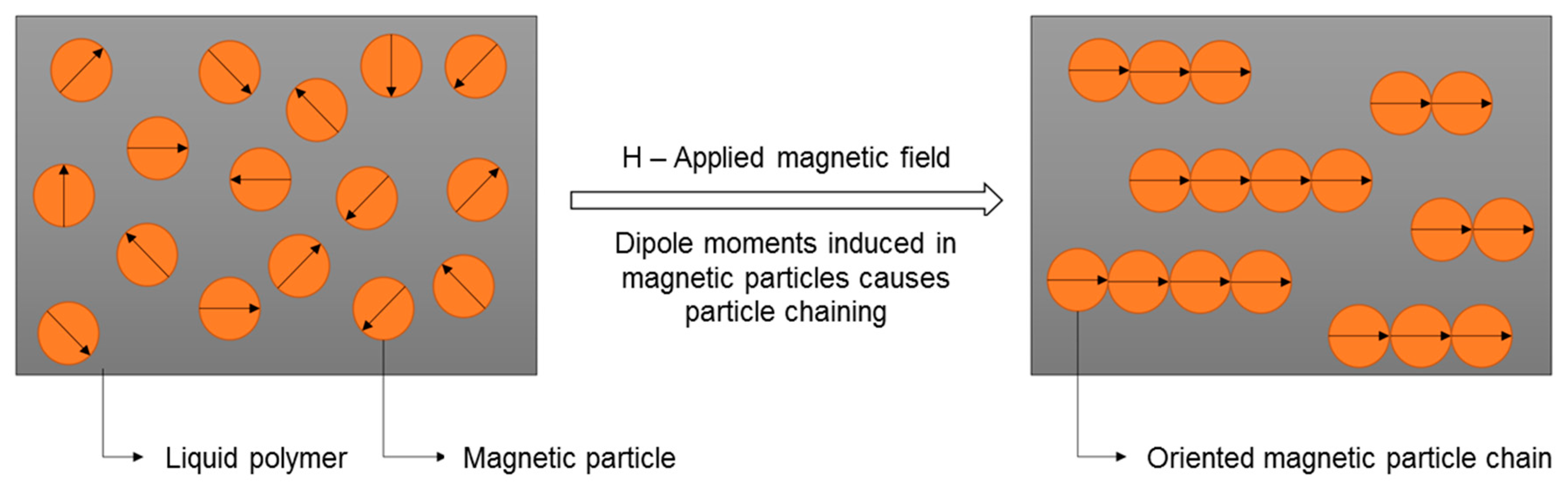
3.3. Magnetic Particle-Reinforced Resin Behavior in Magnetic Field
3.4. Magnetic Particle Aggregation Control in Photopolymers
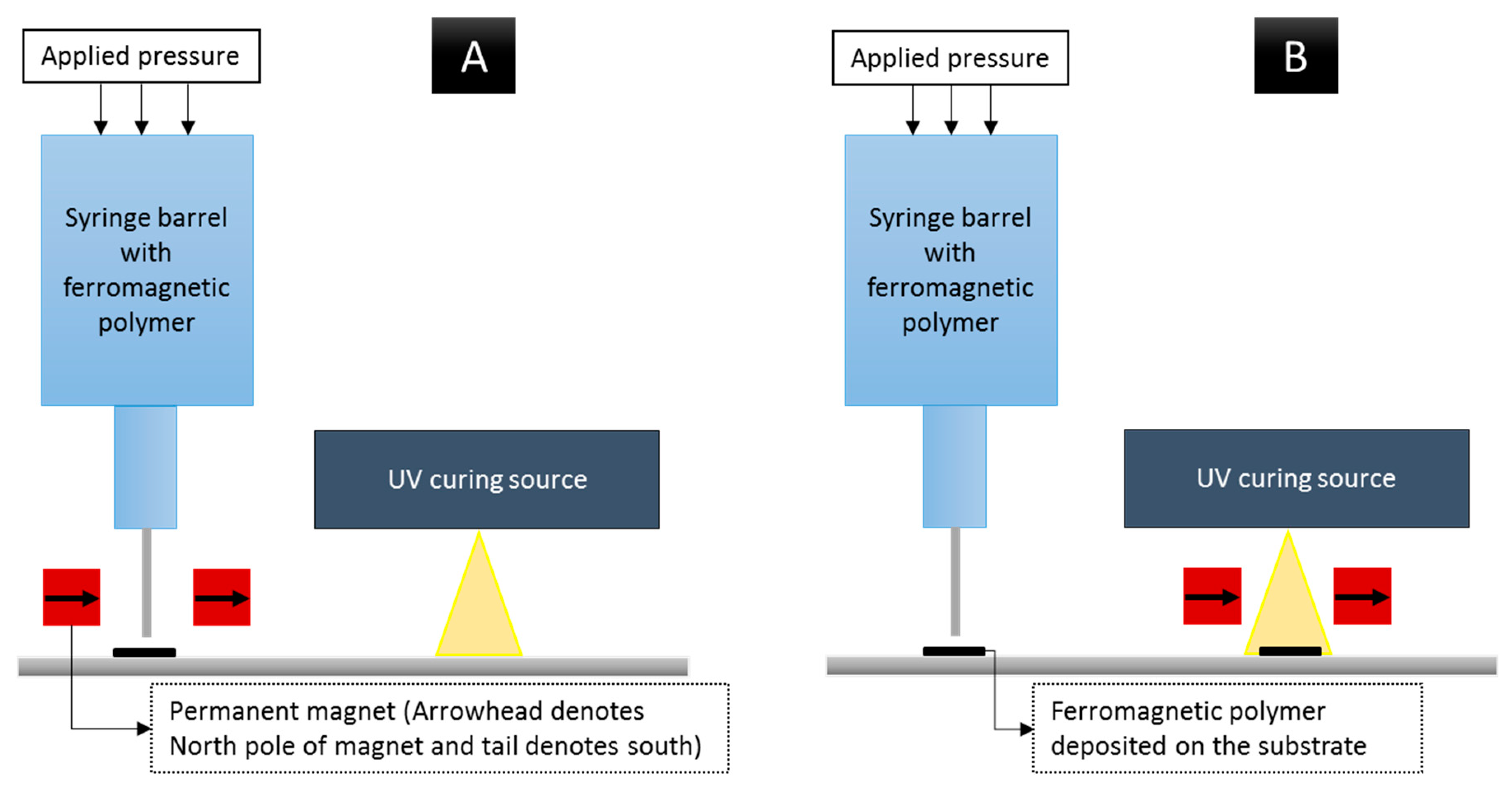
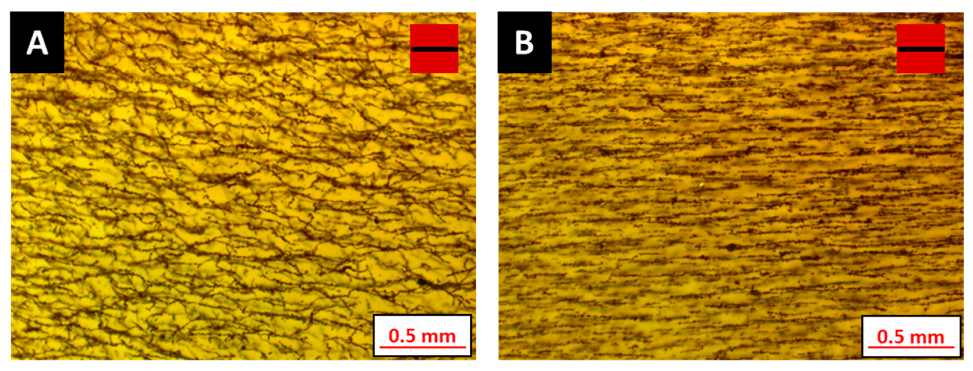
3.5. Manufacturing Scenarios for Particle Structuring, and Influence of Resin Viscosity on Particle Alignment
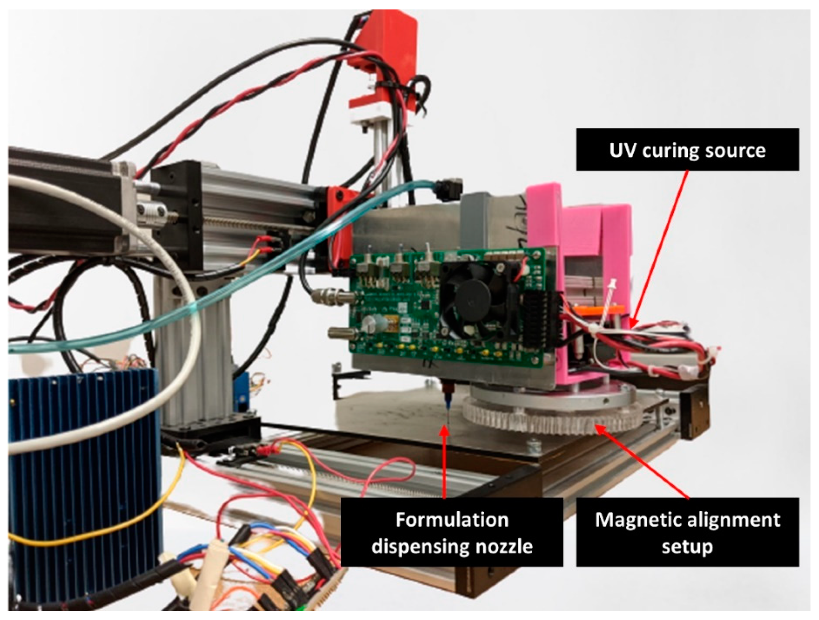
3.6. Additive Manufacturing of Magnetic Polymer Composites and Magnetic Characterization
4. Results and Discussion
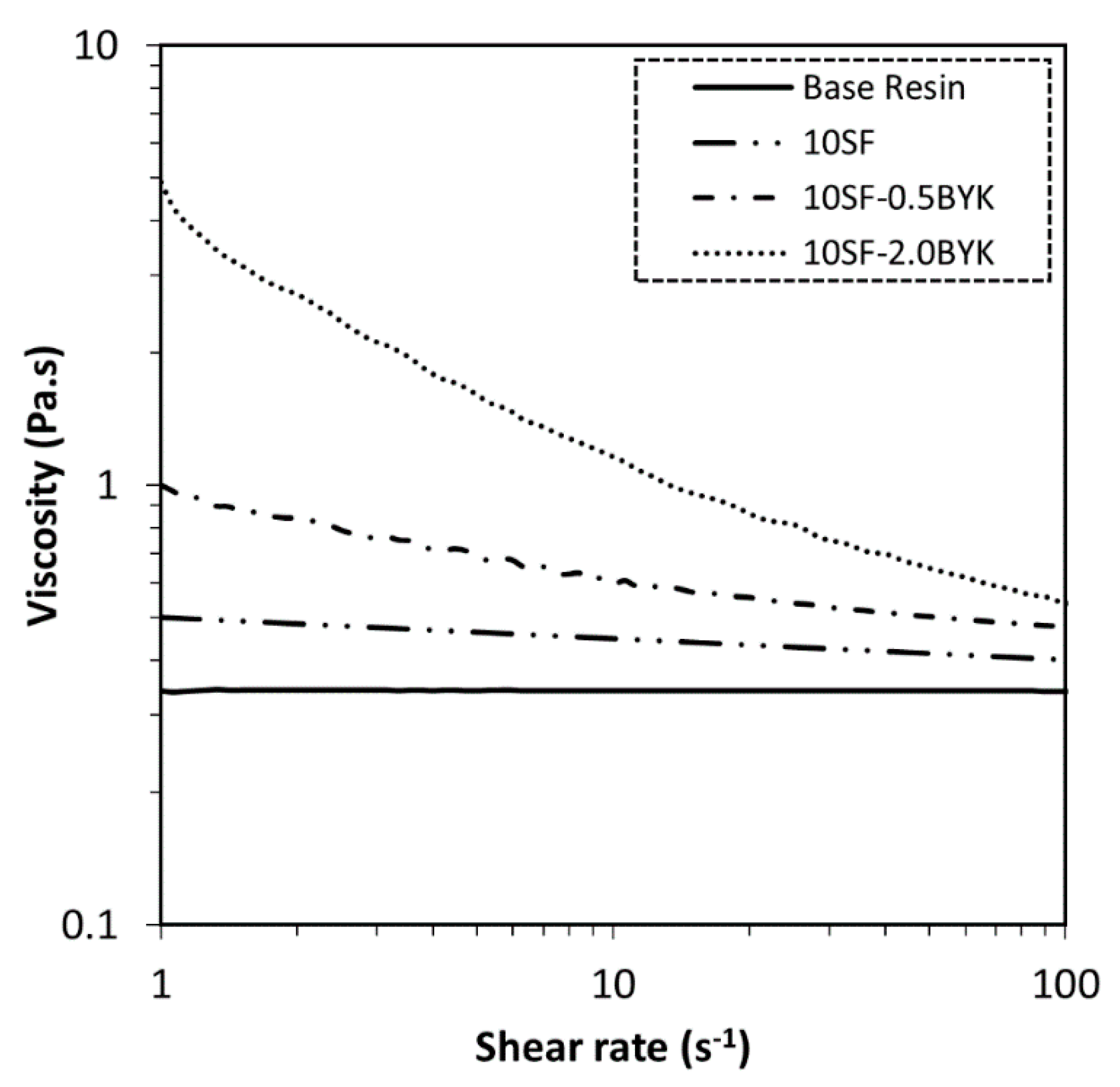
4.1. Rheological Behavior Analysis of Ferromagnetic Polymers
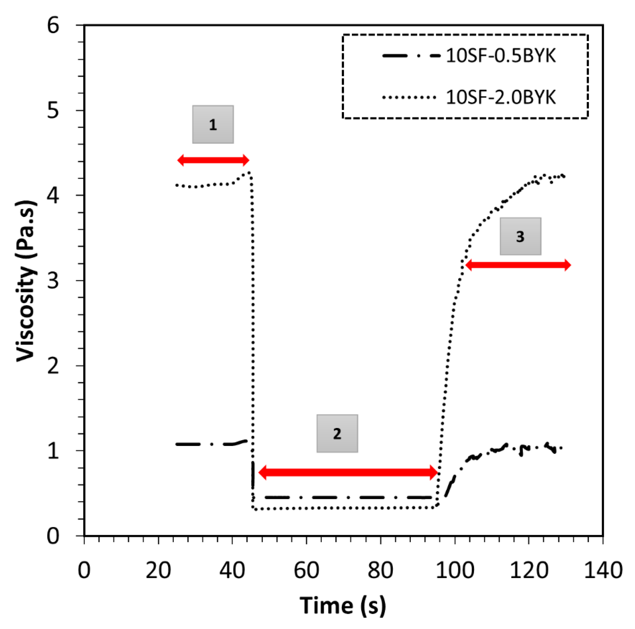
4.2. Thixotropic Flow Behavior Analysis
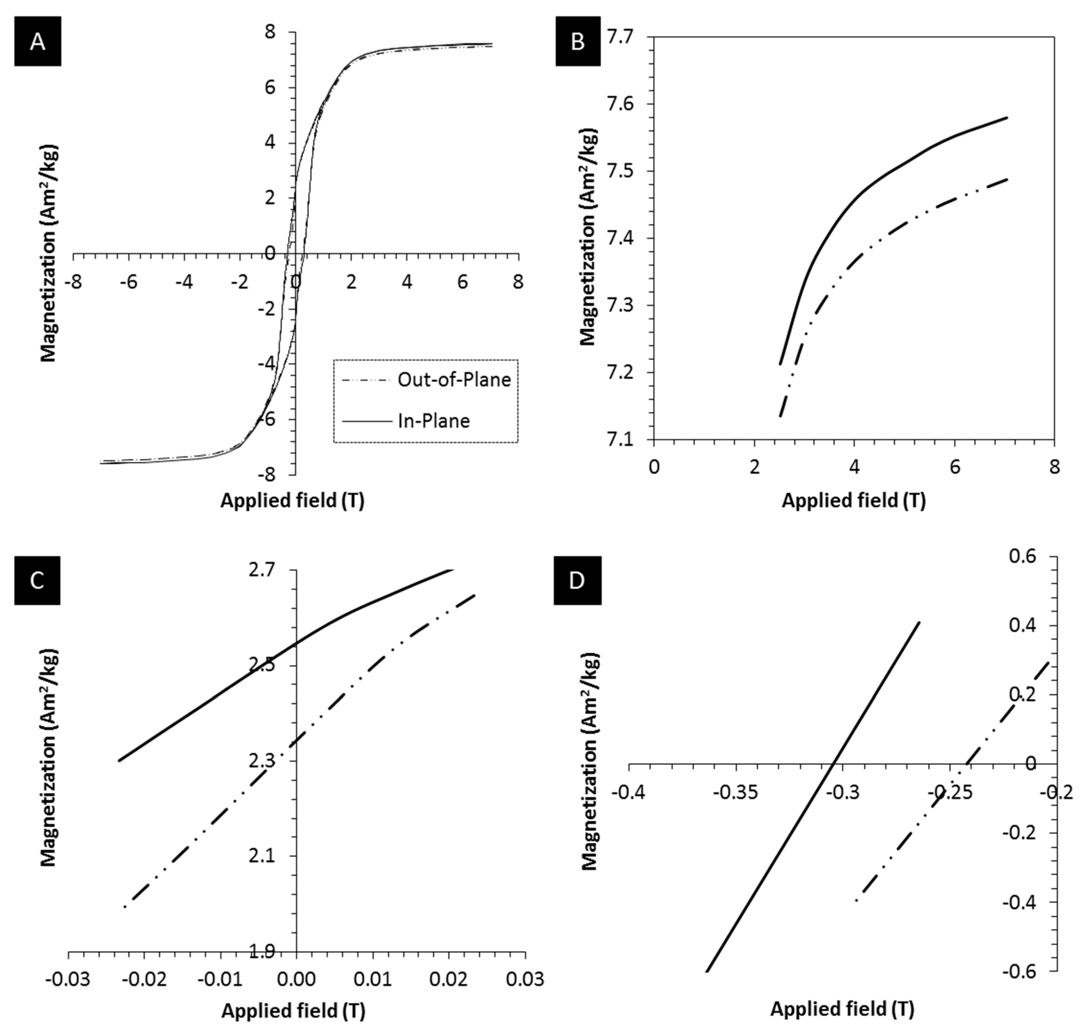
4.3. Magnetic Particle-Reinforced Resin Behavior in Magnetic Field
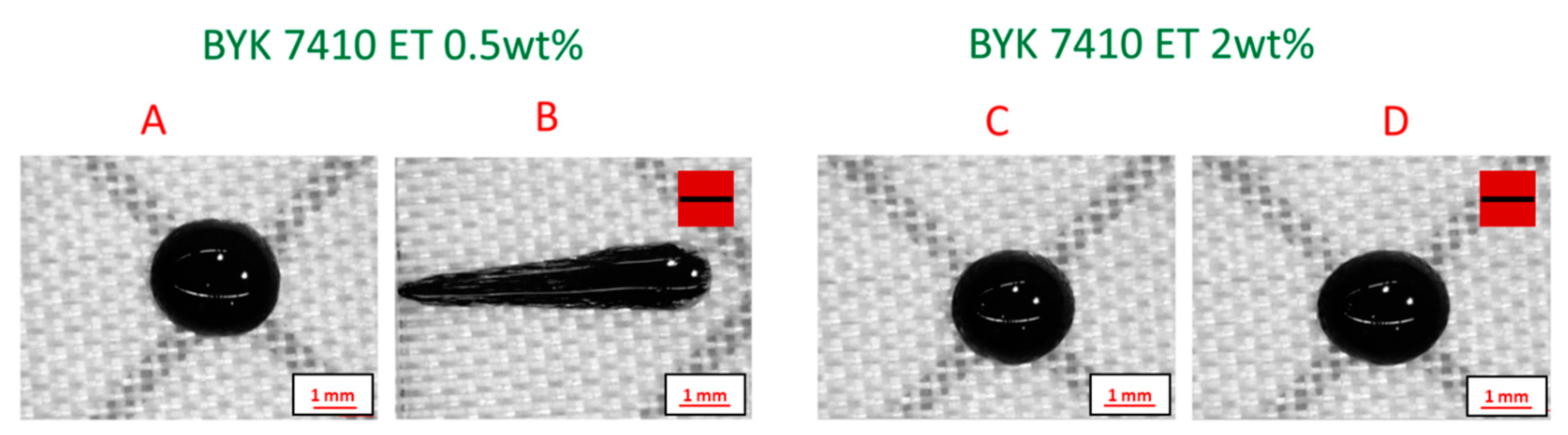
4.4. Magnetic Particle Aggregation Control in Photopolymers
4.5. Manufacturing Scenarios and Influence of Resin Viscosity on Particle Alignment
4.6. Additive Manufacturing of Field-Structured Composites and Magnetic Characterization
5. Conclusions
Author Contributions
Funding
Conflicts of Interest
References
- Gibson, I.; Rosen, D.; Stucker, B. Additive Manufacturing Technologies; Springer: New York, NY, USA, 2015. [Google Scholar] [CrossRef]
- Goswami, A.; Ankit, K.; Balashanmugam, N.; Umarji, A.M.; Madras, G. Optimization of rheological properties of Photopolymerizable alumina suspensions for ceramic Microstereolithography. Ceram. Int. 2014, 40, 3655–3665. [Google Scholar] [CrossRef]
- Goh, G.L.; Saengchairat, N.; Agarwala, S.; Yeong, W.Y.; Tran, T. Sessile droplets containing carbon nanotubes: A study of evaporation dynamics and CNT alignment for printed electronics. Nanoscale 2019, 11, 10603–10614. [Google Scholar] [CrossRef]
- Jabari, E.; Liravi, F.; Davoodi, E.; Lin, L.; Toyserkani, E. High speed 3D material-jetting additive manufacturing of viscous Graphene-based ink with high electrical conductivity. Addit. Manuf. 2020, 35, 101330. [Google Scholar] [CrossRef]
- Oh, Y.; Bharambe, V.; Mummareddy, B.; Martin, J.; McKnight, J.; Abraham, M.A.; Walker, J.M.; Rogers, K.; Conner, B.; Cortes, P.; et al. Microwave dielectric properties of zirconia fabricated using nanoparticle JettingTM. Addit. Manuf. 2019, 27, 586–594. [Google Scholar] [CrossRef]
- Saleh, E.; Zhang, F.; He, Y.; Vaithilingam, J.; Fernandez, J.L.; Wildman, R.; Ashcroft, I.; Hague, R.; Dickens, P.; Tuck, C. 3D inkjet printing of electronics using UV conversion. Adv. Mater. Technol. 2017, 2, 1700134. [Google Scholar] [CrossRef]
- Derby, B. Additive manufacture of ceramics components by inkjet printing. Engineering 2015, 1, 113–123. [Google Scholar] [CrossRef] [Green Version]
- Yang, H.; Lim, J.C.; Liu, Y.; Qi, X.; Yap, Y.L.; Dikshit, V.; Yeong, W.Y.; Wei, J. Performance evaluation of projet multi-material jetting 3D printer. Virtual Phys. Prototyp. 2017, 12, 95–103. [Google Scholar] [CrossRef]
- Yap, Y.L.; Wang, C.; Sing, S.L.; Dikshit, V.; Yeong, W.Y.; Wei, J. Material jetting additive manufacturing: An experimental study using designed metrological benchmarks. Precis. Eng. 2017, 50, 275–285. [Google Scholar] [CrossRef]
- Martin, J.; Venturini, E.; Odinek, J.; Anderson, R. Anisotropic magnetism in field-structured composites. Phys. Rev. E 2000, 61, 2818–2830. [Google Scholar] [CrossRef] [Green Version]
- Erb, R.M.; Segmehl, J.; Charilaou, M.; Löffler, J.F.; Studart, A.R. Non-linear alignment dynamics in suspensions of platelets under rotating magnetic fields. Soft Matter 2012, 8, 7604–7609. [Google Scholar] [CrossRef]
- Kokkinis, D.; Schaffner, M.; Studart, A.R. Multimaterial magnetically assisted 3D printing of composite materials. Nat. Commun. 2015, 6, 8643. [Google Scholar] [CrossRef] [PubMed] [Green Version]
- Romero, J.J.; Cuadrado, R.; Pina, E.; de Hoyos, A.; Pigazo, F.; Palomares, F.J.; Hernando, A.; Sastre, R.; Gonzalez, J.M. Anisotropic polymer bonded hard-magnetic films for Microelectromechanical system applications. J. Appl. Phys. 2006, 99, 08N303. [Google Scholar] [CrossRef]
- Xia, S.; Metwalli, E.; Opel, M.; Staniec, P.A.; Herzig, E.M.; Müller-Buschbaum, P. Printed thin magnetic films based on Diblock copolymer and magnetic nanoparticles. ACS Appl. Mater. Interfaces 2018, 10, 2982–2991. [Google Scholar] [CrossRef] [PubMed]
- Speliotis, D. Magnetic recording beyond the first 100 years. J. Magn. Magn. Mater. 1999, 193, 29–35. [Google Scholar] [CrossRef]
- Goc, K.; Gaska, K.; Klimczyk, K.; Wujek, A.; Prendota, W.; Jarosinski, L.; Rybak, A.; Kmita, G.; Kapusta, C. Influence of magnetic field-aided filler orientation on structure and transport properties of ferrite filled composites. J. Magn. Magn. Mater. 2016, 419, 345–353. [Google Scholar] [CrossRef]
- Gao, M.; Kuang, M.; Li, L.; Liu, M.; Wang, L.; Song, Y. Printing 1D assembly array of single particle resolution for Magnetosensing. Small 2018, 14, 1800117. [Google Scholar] [CrossRef] [PubMed]
- Ho, M.; Nagaraja, S.P.M.; Tok, R.U.; Rangchian, A.; Kavehpour, P.; Wang, Y.E.; Candler, R. Additive manufacturing with strontium Hexaferrite-photoresist composite. IEEE Trans. Magn. 2020. [Google Scholar] [CrossRef]
- Pullar, R.C. Hexagonal ferrites: A review of the synthesis, properties and applications of Hexaferrite ceramics. Prog. Mater. Sci. 2012, 57, 1191–1334. [Google Scholar] [CrossRef]
- Lu, L.; Guo, P.; Pan, Y. Magnetic-field-assisted projection Stereolithography for three-dimensional printing of smart structures. J. Manuf. Sci. Eng. 2017, 139, 071008. [Google Scholar] [CrossRef]
- Nagarajan, B.; Eufracio Aguilera, A.F.; Wiechmann, M.; Qureshi, A.J.; Mertiny, P. Characterization of magnetic particle alignment in photosensitive polymer resin: A preliminary study for additive manufacturing processes. Addit. Manuf. 2018, 22, 528–536. [Google Scholar] [CrossRef]
- Nagarajan, B.; Aguilera, A.F.E.; Qureshi, A.; Mertiny, P. Additive manufacturing of magnetically loaded polymer composites: An experimental study for process development. In ASME 2017 International Mechanical Engineering Congress and Exposition; American Society of Mechanical Engineers: New York, NY, USA, 2017; p. V002T02A032. [Google Scholar]
- Eufracio Aguilera, A.F.; Nagarajan, B.; Fleck, B.A.; Qureshi, A.J. Ferromagnetic particle structuring in material jetting—Manufacturing control system and software development. Procedia Manuf. 2019, 34, 545–551. [Google Scholar] [CrossRef]
- Nagarajan, B.; Arshad, M.; Ullah, A.; Mertiny, P.; Qureshi, A.J. Additive manufacturing ferromagnetic polymers using Stereolithography—Materials and process development. Manuf. Lett. 2019, 21, 12–16. [Google Scholar] [CrossRef]
- Berndlmaier, R. Rheology additives for solvent and Solventless coating. In Handbook of Coating Additives; CRC Press: Boca Raton, FL, USA, 2004; pp. 363–364. [Google Scholar] [CrossRef]
- Bastola, A.K.; Paudel, M.; Li, L. Development of hybrid Magnetorheological elastomers by 3D printing. Polymer 2018, 149, 213–228. [Google Scholar] [CrossRef]
- Chhabra, R.P.; Richardson, J.F. Non-Newtonian Flow and Applied Rheology: Engineering Applications; Butterworth-Heinemann: Oxford, UK, 2011. [Google Scholar]
- Eberhard, U.; Seybold, H.J.; Floriancic, M.; Bertsch, P.; Jiménez-Martínez, J.; Andrade, J.S.; Holzner, M. Determination of the effective viscosity of non-Newtonian fluids flowing through porous media. Front. Phys. 2019, 7, 1–9. [Google Scholar] [CrossRef] [Green Version]
- Mezger, T.G. The rheology handbook. Pigment. Resin Technol. 2009, 38. [Google Scholar] [CrossRef]
- Nagarajan, B.; Kamkar, M.; Schoen, M.A.W.; Sundararaj, U.; Trudel, S.; Qureshi, A.J.; Mertiny, P. Development and characterization of stable polymer formulations for manufacturing magnetic composites. J. Manuf. Mater. Process. 2020, 4, 4. [Google Scholar] [CrossRef] [Green Version]
- Barnes, H.A. Thixotropy—A Review. J. Nonnewton. Fluid Mech. 1997, 70, 1–33. [Google Scholar] [CrossRef]
- López-López, M.T.; Kuzhir, P.; Bossis, G.; Mingalyov, P. Preparation of well-dispersed Magnetorheological fluids and effect of dispersion on their Magnetorheological properties. Rheol. Acta 2008, 47, 787–796. [Google Scholar] [CrossRef]
- Al-Milaji, K.N.; Hadimani, R.L.; Gupta, S.; Pecharsky, V.K.; Zhao, H. Inkjet printing of magnetic particles toward anisotropic magnetic properties. Sci. Rep. 2019, 9, 16261. [Google Scholar] [CrossRef] [Green Version]
- Banerjee, U.; Bit, P.; Ganguly, R.; Hardt, S. Aggregation dynamics of particles in a Microchannel due to an applied magnetic field. Microfluid. Nanofluidics 2012, 13, 565–577. [Google Scholar] [CrossRef]
- Ganguly, R.; Puri, I.K. Field-assisted self-assembly of Superparamagnetic nanoparticles for biomedical, MEMS and BioMEMS applications. Adv. Appl. Mech. 2007, 41, 293–335. [Google Scholar]
- Schindelin, J.; Arganda-Carreras, I.; Frise, E.; Kaynig, V.; Longair, M.; Pietzsch, T.; Preibisch, S.; Rueden, C.; Saalfeld, S.; Schmid, B.; et al. Fiji: An open-source platform for biological-image analysis. Nat. Methods 2012, 9, 676–682. [Google Scholar] [CrossRef] [PubMed] [Green Version]
- Ranellucci, A. Slic3r. Available online: https://slic3r.org/ (accessed on 30 September 2019).
- Ajinjeru, C.; Kishore, V.; Chen, X.; Hershey, C.; Lindahl, J.; Kunc, V.; Hassen, A.A.; Duty, C. Rheological survey of carbon fiber-reinforced high-temperature thermoplastics for big area additive manufacturing tooling applications. J. Thermoplast. Compos. Mater. 2019. [Google Scholar] [CrossRef]
- Ajinjeru, C.; Kishore, V.; Liu, P.; Hassen, A.A.; Lindahl, J.M.; Kunc, V.; Duty, C.E. Rheological Evaluation of High. Temperature Polymers to Identify Successful Extrusion Parameters; Oak Ridge National Lab (ORNL): Oak Ridge, TN, USA, 2017. [Google Scholar]
- Kamkar, M.; Nourin Sultana, S.M.; Patangrao Pawar, S.; Eshraghian, A.; Erfanian, E.; Sundararaj, U. The key role of processing in tuning nonlinear viscoelastic properties and microwave absorption in CNT-based polymer Nanocomposites. Mater. Today Commun. 2020, 24, 101010. [Google Scholar] [CrossRef]
- Hoseini, A.H.A.; Arjmand, M.; Sundararaj, U.; Trifkovic, M. Significance of interfacial interaction and agglomerates on electrical properties of polymer-carbon nanotube Nanocomposites. Mater. Des. 2017, 125, 126–134. [Google Scholar] [CrossRef]
- Kunc, V.; Lee, A.; Mathews, M.; Lindahl, J. Low cost reactive polymers for large scale additive manufacturing. In Proceedings of the CAMX—The Composites and Advanced Materials Expo, Dallas, TX, USA, 15–18 October 2018. [Google Scholar]
- Deka, A.; Dey, N. Rheological studies of two component high build epoxy and polyurethane based high performance coatings. J. Coat. Technol. Res. 2013, 10, 305–315. [Google Scholar] [CrossRef]
- Song, H.; Spencer, J.; Jander, A.; Nielsen, J.; Stasiak, J.; Kasperchik, V.; Dhagat, P. Inkjet printing of magnetic materials with aligned anisotropy. J. Appl. Phys. 2014, 115, 17E308. [Google Scholar] [CrossRef]


| Material Code | Magnetic Filler Loading (wt%) | Additive Type | Additive Loading (wt%) |
|---|---|---|---|
| Base resin | - | - | - |
| 10SF | 10 | - | - |
| 10SF-0.5BYK | 10 | BYK-7410ET | 0.5 |
| 10SF-2.0BYK | 10 | BYK-7410ET | 2 |
| Material Code | n - Power Law Index | m - Viscosity (Pa·s) |
|---|---|---|
| Base resin | - | - |
| 10SF | 0.95 | 0.50 |
| 10SF-0.5BYK | 0.87 | 0.88 |
| 10SF-2.0BYK | 0.61 | 3.23 |
| Material Code | Herschel–Bulkley Model predictions | ||
|---|---|---|---|
| Yield Strength - (Pa) | Consistency index - (Pa·s) | Herschel-Bulkley index - | |
| Base resin | - | - | - |
| 10SF | 0.26 | 0.45 | 0.97 |
| 10SF-0.5BYK | 0.65 | 0.59 | 0.93 |
| 10SF-2.0BYK | 3.07 | 1.18 | 0.81 |
| Material Code | Thixotropy Index |
|---|---|
| 10SF-0.5BYK | 0.05 |
| 10SF-2.0BYK | 0.32 |
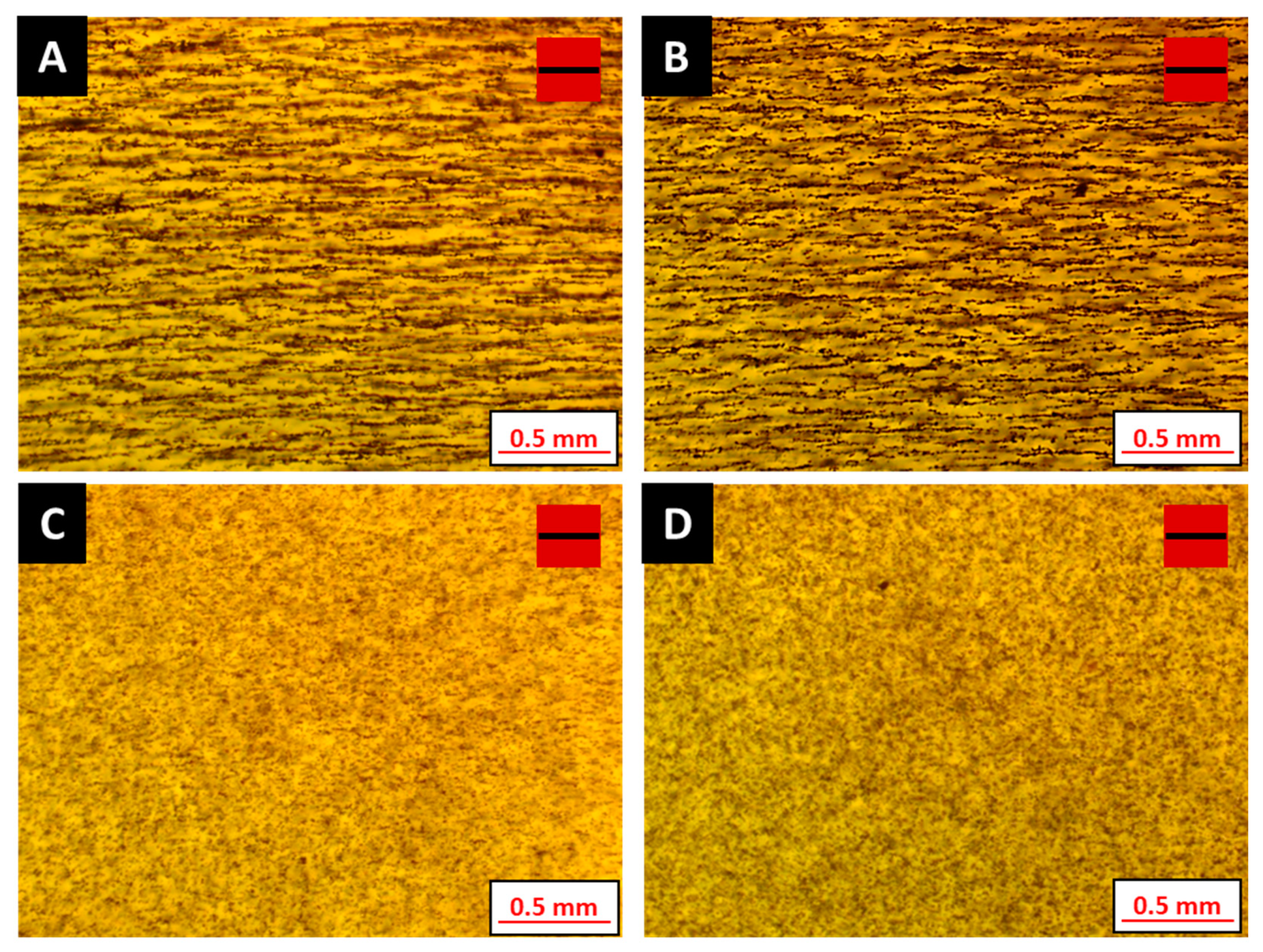
| Sample Identifier | Magnetic Filler Loading (wt%) | BYK 7410ET Additive Loading (wt%) |
|---|---|---|
| A | 0.5 | 0 |
| B | 0.5 | 0.5 |
| C | 0.5 | 1.0 |
| D | 0.5 | 2.0 |
© 2020 by the authors. Licensee MDPI, Basel, Switzerland. This article is an open access article distributed under the terms and conditions of the Creative Commons Attribution (CC BY) license (http://creativecommons.org/licenses/by/4.0/).
Share and Cite
Nagarajan, B.; Schoen, M.A.W.; Trudel, S.; Qureshi, A.J.; Mertiny, P. Rheology-Assisted Microstructure Control for Printing Magnetic Composites—Material and Process Development. Polymers 2020, 12, 2143. https://0-doi-org.brum.beds.ac.uk/10.3390/polym12092143
Nagarajan B, Schoen MAW, Trudel S, Qureshi AJ, Mertiny P. Rheology-Assisted Microstructure Control for Printing Magnetic Composites—Material and Process Development. Polymers. 2020; 12(9):2143. https://0-doi-org.brum.beds.ac.uk/10.3390/polym12092143
Chicago/Turabian StyleNagarajan, Balakrishnan, Martin A.W. Schoen, Simon Trudel, Ahmed Jawad Qureshi, and Pierre Mertiny. 2020. "Rheology-Assisted Microstructure Control for Printing Magnetic Composites—Material and Process Development" Polymers 12, no. 9: 2143. https://0-doi-org.brum.beds.ac.uk/10.3390/polym12092143