Electrospun Functional Nanofiber Membrane for Antibiotic Removal in Water: Review


School of Materials Science & Engineering, University of Shanghai for Science & Technology, 516 Jun-Gong Road, Shanghai 200093, China
*
Author to whom correspondence should be addressed.
Polymers 2021, 13(2), 226; https://0-doi-org.brum.beds.ac.uk/10.3390/polym13020226
Submission received: 28 December 2020
/
Revised: 8 January 2021
/
Accepted: 8 January 2021
/
Published: 11 January 2021
(This article belongs to the Special Issue Electrospun Biomaterials)
Abstract
:As a new kind of water pollutant, antibiotics have encouraged researchers to develop new treatment technologies. Electrospun fiber membrane shows excellent benefits in antibiotic removal in water due to its advantages of large specific surface area, high porosity, good connectivity, easy surface modification and new functions. This review introduces the four aspects of electrospinning technology, namely, initial development history, working principle, influencing factors and process types. The preparation technologies of electrospun functional fiber membranes are then summarized. Finally, recent studies about antibiotic removal by electrospun functional fiber membrane are reviewed from three aspects, namely, adsorption, photocatalysis and biodegradation. Future research demand is also recommended.
1. Introduction
Water is one of the resources for human survival and is the most abundant covering 3/4 of the Earth’s surface [1]. However, the available freshwater accounts for approximately 3% of the total amount of water on the planet. Hence, water is a precious and scarce resource. Water pollution by the heavy industry, chemical industry and other highly polluting enterprises has dramatically aggravated the shortage of freshwater worldwide. The World Watch Institute stated that water shortages may affect more than 2/3 of the world’s population by 2025, including almost every country in the world, even developed ones [2]. Therefore, the treatment of sewage and wastewater has become a hot research topic.
Many kinds of pollutants, such as colored dyes [3,4,5], heavy metal ions [6,7,8], harmful bacteria [9,10,11] and drugs [12,13,14], are harmful to water. Among them, antibiotics have attracted attention as a new water pollutant [15,16]. These substances are compounds synthesized partly or entirely by microorganisms to kill or inhibit the growth of other organisms [17]. Antibiotics have many types. Table 1 classifies the common antibiotics according to their mechanism and includes statistics on some of their physical and chemical properties. In the early 20th century, the discovery of antibiotics has brought good news to human beings. This drug is widely used to treat human and animal diseases caused by microbial infections [18] and as a growth promoter in agriculture, aquaculture, beekeeping, livestock and other fields [19].
The antibiotics consumed by humans and animals cannot be fully absorbed by the body [20], and approximately 10–90% are discharged into the environment in the form of parent compounds or biodegradable metabolites [21]. Antibiotic pollutants are difficult to biodegrade and thus can exist stably for a long time in the environmental matrix [22]. In addition, antibiotic contaminants seriously influence antibiotic-resistant bacteria and genes, thus reducing the effectiveness of traditional antibiotics and promoting the production of drug-resistant bacteria [23]. These substances may also combine with other pollutants in water to produce highly toxic compound pollutants [24]. Antibiotics pose a potentially enormous threat to human health and ecosystems [25]. In 1982, Watts, C. D. [26] detected drugs (macrolides, sulfonamides and tetracyclines) in the river water—the first case of antibiotic contamination in surface water. Currently, the level of antibiotics reaches the range of ng/L in surface water, groundwater and seawater; its amount in low of urban sewage and generally high in the range of mg/L in hospital sewage [17]. Hence, antibiotic wastewater treatment is urgent.
The sewage treatment plant is the last barrier before the wastewater is discharged into the environment. Manvendra et al. [27] pointed out that the sewage treatment plant is designed to degrade the easily and moderately degradable organic matter within the range of mg/L. However, antibiotics mainly exist in in the water at the concentration of ng/L to μg/L and exhibit high activity. Therefore, the sewage treatment plant can partially remove antibiotics but is not suitable for their complete removal. Figure 1 summarizes the following existing techniques for the removal of antibiotic pollutants in water: (1) physical method, which changes the drug from the liquid phase to the solid phase; (2) chemical and biological treatments, which transform the drug into new metabolites and degradation products through chemical reactions [27] and (3) advanced oxidation (mainly ozonation, Fenton and Photo Fenton processes), which includes physical (such as physical adsorption) and chemical reactions. The application of these technologies has achieved good results in the treatment of antibiotic-contaminated wastewater. However, the process must be continuously updated.
Electrospun fiber membrane has the advantages of a small diameter, large specific surface area, high porosity (up to 80% or higher), good connectivity, small pore size, high surface roughness and low gram weight [28]. The advantages of existing technologies to treat antibiotic wastewater can be fully utilized by using electrospun fiber membrane as a load functional substance carrier. Nanofiber-based composites can overcome inherent limitations of bare nanofiber systems (e.g., physical, chemical and catalytic properties) and remove antibiotic pollutants more effectively. Studies on the topics of “Electrospun nanofibers for antibiotic treatment” and “Antibiotic treatment” were searched on the “Web of Science” platform, and the results are shown in Figure 2. The number of related articles published on the two topics has generally increased every year. The total number of articles retrieved on the subject of “Antibiotic treatment” is more than 9000 articles per year from 2012 to 2019, indicating that the topic of antibiotic removal is highly relevant. However, the maximum number of articles corresponding to the theme of “Electrospun nanofibers for antibiotic treatment” is no more than 30 articles per year on the platform. This value indicates a room for improvement for the use of electrospun fiber membrane in antibiotic pollution control.
2. Electrospinning
In wastewater treatment, polymer membranes have shown excellent application potential due to their superior performance. To date, the preparation technologies for polymer membranes include electrospinning, template synthesis, interfacial polymerization, self-assembly, phase inversion, stretching, sintering and track etching [30,31]. As a “top-down” membrane technology [32], electrospinning can prepare fibers with a diameter in the range of several hundred nanometers in large quantities within a short time [33]. The diameter and orientation of the fibers can also be easily controlled [34]. This technology also has the advantages of simple operation, low cost, high efficiency and excellent flexibility. Therefore, electrospun fiber membranes have become research hotspots in the field of water treatment [35]. An in-depth research on electrospinning technology is warranted.
2.1. Initial Development History of Electrospinning
The creation and development of each technology are accompanied by the tortuous process and grinding of time, and electrospinning is no exception. Figure 3 summarizes the primary development history nodes of electrospinning. As early as 1600 A.D. William Gibert [36] found that a droplet interacts with the electrostatic field force in a high-voltage electric field. When a certain amount of electric charge is present on its surface, the droplet deforms into a cone shape and a tiny droplet is ejected from the tip of the cone. He also put forward the concept of “electrospinning”. At the beginning of the 18th century, Stephen Gray mentioned that water droplets undergo electrodynamic atomization in the electrostatic field, and tiny jets are ejected from the tip of the liquid during this process [37]. In 1747, Abbe Nollet performed the earliest known electrospraying experiments and found that water could be sprayed into aerogel in an electrostatic field [38]. Since then, theoretical research on electrospinning has propagated. In 1882, Lord Rayleigh [39] theoretically estimated the maximum charge on the surface of droplet before straight jet injection and provided an essential theoretical basis for further research on the principle of electrospinning. In 1902, John Cooley [40] and William Morton [41] applied for two patents to design prototypes of an electrospinning device. From 1934 to 1944, Anton Formhals successively applied for some patents to improve the electrospinning device, thus allowing the electrospinning technology to move toward commercial production [42]. The preparation technology for electrospinning has matured with the continuous research efforts. However, the understanding of electrospinning mechanics is still in the early stages. In 1964–1969, Geoffrey Taylor published many pioneering works using mathematical language and modeling to describe the change process of solution or melt droplet from spherical to conical under the action of a high-voltage electric field [43,44,45]. Owing to his outstanding contribution, the cone-shaped hemisphere formed by droplets under high-voltage electric field is called “Taylor cone” [46]. In the next 20 years, electrospinning technology did not attract attention from the scientific research and industrial circles. In 1990, some research groups represented by Darrell Reneker and Gregory Rutledge reinvented and promoted electrospinning technology. Their works confirmed that a large number of polymer solutions could be electrospun into fiber membranes [47]. This discovery brought new life to electrospinning and has ushered it in a prosperous period of development. A search with the subject word “Electrospinning” was conducted on the “Web of Science” and produced 42,269 items (11 December 2020). This number will continue to increase in the near future.
2.2. Working Process and Principle of Electrospinning
Electrospinning is an advanced fiber preparation technology that uses the interaction between the liquid and electric field to generate products [48]. The apparatus and the process are shown in Figure 4. The electrospinning apparatus is mainly composed of the syringe pump, syringe, spinneret, high-voltage power supply and collector device (commonly used types are aluminum foil and roller). The process and technical principle of electrospinning can be divided into the following three stages [49]. (1) Driven by the syringe pump, the liquid inside the syringe is extruded from the spinneret. The droplet forms a spherical shape at the tip of the spinneret due to the balance of surface tension and gravity. (2) When the electric field force is applied, the surface morphology of the droplet gradually changes from spherical to a conical shape due to the enrichment of electric charges. This process is controlled by gravity, Coulomb force and surface tension. The tip of the cone emits straight jet when the Coulomb force is greater than the surface tension. (3) According to the Rayleigh instability principle and the interaction of the positive charges on the jet surface in the electric field, the duration of the straight jet section is short and thus results in bending and whipping. Owing to Coulomb repulsion force and gravity interaction on its surface, the jet is stretched rapidly in the bending whip section and then solidified into the fiber with the rapid solvent evaporation. The critical voltage of emitting straight jet at hemispherical cone tip can be calculated according to the formula [50]:
where is the critical voltage of emitting straight jet at the hemispherical cone tip (kV), is the surface tension of the hemispherical cone (kg/s2), is the distance between the positive and negative electrodes (m), is the dielectric constant (C2/(Jm)) and is the curvature (m) of the hemispherical cone. When the applied voltage exceeds the critical voltage, the charge on the hemispherical cone surface reaches the critical charge and the tip of the cone can emit straight jet to start the electrospinning process.
Electrospraying is also a common technology, and electrospinning is a special case of electrospraying [51,52,53]. Their main difference is the viscosity of working fluids that results in various jet behaviors. Electrospinning involves highly viscous working liquid, and the jet can maintain a continuous form to produce fibers. Electrospraying involves low-viscosity working liquid, and the jet cannot maintain a consistent form and splits into particles [28]. The entanglement number can be used to quantitatively calculate whether the polymer solution can be spinnable as shown in the following formula [54]:
where is the relative molecular weight of the polymer, is the entangled molecular weight that mainly refers to the average molecular weight between entangled knot and is the polymer concentration. When < 2, nanoparticles are produced by pure electrospraying. When 2 < < 3.5, the nanoparticles gradually change into bead-like fibers (or spindles-like fibers). When > 3.5, continuous fibers are produced by pure electrospinning due to the sufficient chain entanglement of the polymer solution.
2.3. Influencing Factors of Electrospinning
The parameters affecting the morphology of electrospun nanofibers can be grouped into three categories: system, process and environmental [55]. System parameters include polymer molecular weight, polymer solution concentration, polymer solution conductivity, dielectric constant, surface tension, viscosity and solvent type; process parameters mainly refer to the applied voltage, fluid flow rate, linear receiving distance from the tip of the spinneret to the collector and diameter of spinneret; and environmental parameters mainly include the humidity and temperature of the surrounding environment [56]. The influence of these parameters on the morphology of the electrospun fibers must be within a specific range, and the interaction between the parameters should be considered. Table 2 summarizes the effects of these parameters on the morphology of electrospun nanofibers.
2.3.1. System Parameters
System parameters are mainly related to the properties of polymer solution for electrospinning and mainly affect the morphology of electrospun nanofibers.
The molecular weight of polymer is usually positively correlated with the physical properties of polymer solution (such as the viscosity of polymer solution, entanglement degree of molecular chain and rheological property) [57]. Its effect on fiber morphology is closely related to the properties above. Bilal Zaarour et al. used three kinds of PVDF with different molecular weights (Mw = 180,000, 275,000 and 530,000) to prepare electrospun fiber membranes. The fibers designed by PVDF with high molecular weight had thick diameters. When the molecular weight is high, the viscosity of the polymer solution is also high; the increase in the tension resistance of the jet from the spinneret results in the formation of large diameter PVDF fibers [58]. However, when the molecular weight is below the critical number, spray particles or bead-like fibers are easily formed because of Rayleigh instability [59].
When other parameters are constant, the concentration of polymer spinning solution can substantially affect the surface morphology of the fiber. Determining the suitable concentration of polymer spinning solution to prepare the best morphology fibers is also called the exploration of the spinning window. Xu et al. [60] mentioned that the polymer has a narrow spinning window in a particular solvent, and the spinning window of gliadin in HFIP is 15–20% (w/v). When the working fluid concentration is from 5% (w/v) to 20% (w/v), the morphology of the prepared products changes from particles to beads and then to a straight line. When the concentration continues to increase to 25% (w/v), the viscosity of the gliadin solution becomes excessively high. The spinneret becomes blocked by the surrounding semi-solid substances, thus preventing normal electrospinning.
The electrical conductivity of the solution is another important factor affecting fiber morphology. Proper electrical conductivity supplies the jet surface with an appropriate charge during electrospinning; thus, fibers with good morphology are formed. When the electrical conductivity increases in a specific range, the surface charge density of the jet and the Coulomb repulsion force between the jet surface and the layer also increases. In this situation, the enhancement of the bending whipping effect during electrospinning is conducive to the formation of fibers with a small diameter. However, the bending whipping of the jet is unstable under a strong electric field and forms fibers with uneven diameter distribution. Excessively high electrical conductivity hinders the formation of Taylor cone, and prevents spinning to normally proceed. Adulteration of salt compounds in the working fluid can increase the electrical conductivity to prepare fibers with good morphology. After adding NaCl to PCL spinning solution, Vince Beachley et al. [61] found that the diameter of fibers decreased with the increase in NaCl concentration. Under constant parameters, bead-like fibers could be observed when no NaCl was added in the working fluids. The diameter of the fiber can also be increased by increasing the electrical conductivity of the polymer solution through salt addition. Fuat Topuz et al. [62] used the self-polymerizing microporous polymer (PIM) solution to prepare fibers and found that the working fluid could be electrospun at a low concentration to form fibers after ammonium salt addition. However, the diameter of the fiber slightly increased possibly because the addition of ammonium salt had increased the viscosity of the polymer solution.
The dielectric constant of the solvent used in the polymer working fluid has an essential influence on the electrospinning process. Luo et al. found that electrospun PCL fibers with diameters less than 100 nm can be obtained when the dielectric constant of the solvent is 19 or higher. At low values, the products are fibers or residues with diameters in the range of submicrons to millimeters [63]. The applied voltage required for stable electrospinning increases with the increase in the dielectric constant of the solvent system. The jet becomes unstable when the dielectric constant of the selected solvent is extremely high.
Surface tension refers to the force applied on the surface plane per unit length [64] and has a particular influence on the electrospinning process and fiber morphology. In electrospinning, the Taylor cone can be formed only when the electrostatic repulsion on the surface of the droplet is greater than the surface tension, thus initiating the spinning process. High surface tension often requires a high voltage to break for a stable spin, thus hindering the formation of Taylor cone and affecting the normal spinning process [65]. The choice of solvent can directly determine the surface tension of the polymer solution. Yang et al. [66] systematically studied the effect of surface tension on the morphology of electrospun products by using PVP as a polymer model and ethanol, DMF, and MC as solvents. The results showed that different solvents lead to varying surface tensions. At fixed concentration, the bead-like fibers can be transformed into smooth linear fibers by using the solvent with low surface tension. When other conditions are fixed, the surface tension determines the upper and lower boundaries of the spinning window [67].
Viscosity is closely related to and determined by molecular weight and entanglement degree. High polymer concentration and large molecular weight indicate that the polymer chain has a high entanglement degree; in addition, the mobility of the chain in the solution is low, thus preventing the reordering of the chain and increases the viscosity of the solution [68]. Therefore, the effect of viscosity on fiber morphology is the same as that of concentration and molecular weight. Andrea Dodero et al. increased the viscosity by increasing the concentration of the working fluid and found that the uniformity and global structure of prepared electrospun chitosan fibers can be improved by increasing the solution viscosity [69]. The choice of solvent also affects the viscosity of the working fluid. Juliana et al. [70] used PI as a polymer template and selected four best solvents for PI (NMP, DMF, DMAc and DMSO) for electrospinning experiments. Large diameter PI fiber could be obtained by using the solvent with high viscosity. When the other parameters remain unchanged, the use of high-viscosity solvent extends the fiber beads. The linear distance between the beads and beads increases, and the fiber morphology changes from bead-like to spindle-like.
Solvent type determines many properties of the working fluid, such as dielectric constant, surface tension and viscosity. Solvent selection is important for the preparation of nanofibers with good morphology. The solubility of the polymer in the solvent and the boiling point of the solvent are two crucial considerations in the selection of solvents [71]. First, the polymer needs to have good solubility in the solvent; that is, the solvent molecule needs to overcome the intermolecular force in the polymer. In the electrospun polymer solution, mixed solvents can be used to control the fiber surface morphology to prepare smooth or porous fibers. Hoik Lee et al. [72] used mixed solvents to dissolve CA and studied the effects of different solvents on the surface morphology of CA fibers. DMF is a good solvent for CA, whereas acetone and MC are not suitable for CA. When other parameters are kept constant, the fiber with a smooth surface can be obtained efficiently by increasing the proportion of unsuitable solvents. Given that CA can only dissolve well in a good solvent, increasing the ratio of a not-good solvent reduces the space of CA diffusion in the solvent. Therefore, the viscosity of CA solution increases, and smooth fibers without beads can be prepared. When acetone and MC were selected as the mixed solvent of CA solution, the fiber surface was porous because the polymer could not exist uniformly in the solvent and could not spread correctly during spinning, thus resulting in rough and porous morphology. Second, the volatility of the selected solvent must also be considered for the preparation of fibers with good morphology. Highly volatile solvents easily cause spinneret blockage and thus should be avoided. Medium volatile solvents are beneficial to the spinning process and form bead-free fibers. Low volatile solvents are not conducive to spinning and hinder the solvent volatilization of the jet in the process of straight jet and bending whipping, thus easily producing bead-like fibers.
2.3.2. Process Parameters
Process and system parameters can all affect the morphology of electrospun fibers. Process parameters are also known as operating parameters. Herein, the effects of voltage, flow rate, receiving distance and spinneret diameter on fiber morphology are summarized.
In electrospinning, the applied voltage directly determines the charge density of the jet surface and the Coulomb repulsion force. Increasing the voltage also increases the charge density on the jet surface, which in turn increases the Coulomb repulsion between the surface and the layer of the curved whipping section during spinning. Hence, the stretching effect of the jet is enhanced, and fibers with small diameters are formed. Seyed Jalaledin Najafi et al. [73] explored the effect of process parameters on the morphology of glass fibers (ethyl orthosilicate and PVP are the main polymer components). When the voltage was increased from 20 to 26 kV, the average diameter of glass fibers decreased gradually. When the voltage continued to grow to 28 kV, the average diameter of glass fibers increased. The increase in the average diameter of fibers with the applied voltage is also reflected in the study of Fuat Topuz et al. [74]. Their explanation for this phenomenon is that the increase in voltage also increases the flow of liquid at the spinneret, thus expanding the diameter of the fiber. This idea emphasizes the interaction between voltage and liquid flow. Another angle can be explored for this phenomenon. The increase in voltage accelerates the volatilization of the solvent during spinning. Hence, the jet does not have sufficient time to stretch, and the fibers with a large diameter are obtained. Therefore, the effect of voltage on fibers’ morphology must be considered within a specific critical value, and the influence of other parameters should not be neglected.
When other parameters remain unchanged, increasing the liquid flow rate during electrospinning will increase the diameter of the fibers but will produce fibers with poor surface morphology (fibers with spindles-like or bead-like) [75,76,77]. The increase in flow rate implies that many products are obtained in a fixed time, but the drying time of the jet in the corresponding spinning process is substantially shortened [71].
The receiving distance in the electrospinning process usually refers to the linear distance between the tip of the spinneret and the collector device. The effect of receiving distance on the fibers’ morphology is generally related to other parameters (voltage and solvent volatilization rate). After the receiving distance is increased within the critical range, the jet can be fully stretched in the bending and whipping process, and fibers with a small diameter can be obtained. When the increasing degree of the receiving distance exceeds the critical receiving distance, the electrostatic field force decreases, which is not conducive to the stretching of the jet. On the contrary, the fibers with a large diameter are obtained [78].
The diameter of the spinneret affects the diameter of the electrospun fiber, but the specific mechanism remains unclear. Until He et al. [79] used spinnerets with different diameters to prepare PEO nanofibers for rheological experiments and the shear flow model to analyze the effect of spinneret diameter on PEO fibers’ diameter. The liquid viscosity on the tip of the spinneret with a larger diameter is higher; hence, the essence of spinneret diameter on fibers’ morphology is the effect of fluid viscosity on fibers.
2.3.3. Environmental Parameters
Environmental parameters are the secondary parameters that affect the morphology of electrospun fibers. The influence of environmental parameters on the morphology of electrospun fibers is closely related to other parameters. Huang et al. [80] studied the effect of temperature on the morphology of PVDF fibers and found that the diameter of PVDF fibers decreased and the fiber surface became rough with the increase in temperature. When the ambient temperature is increased appropriately, the surface tension and viscosity of the solution decrease; hence, the fiber with a small diameter will be formed. When a mixed solvent of DMF and acetone is used to dissolve PVDF, the high boiling point of DMF hinders the volatilization of low boiling point acetone, thus giving the fiber surface a ravine shape, which is evident at high temperatures. Cui et al. [81] also found that the fibers’ diameter decreased with the increase in temperature. Environmental humidity affects the fiber morphology mainly by influencing the solvent volatilization rate in the spinning process [82]. When the humidity is increased, the solvent volatilization on the jet surface is not complete and bead-like fibers with poor morphology are easily formed. Therefore, ambient temperature and humidity have a particular influence on fibers’ morphology.
2.4. Process Type of Electrospinning Technology
With the in-depth understanding of electrospinning technology, electrospinning technology is continuously being upgraded and optimized. Figure 5 shows that according to the number of working fluids in the spinning process, the electrospinning process can be divided into single- and multifluid electrospinning technology. Multifluid electrospinning technology can further be classified according to the spinnable of the outer fluid into traditional and modified electrospinning technology. Traditional electrospinning technology can also be divided into coaxial and side-by-side electrospinning technology according to the spatial position of the working fluid. Different nanostructures can be prepared by different electrospinning processes, such as core–sheath [83] and Janus [84].
In 2002, Loscertales, I. G. et al. [85] performed coaxial electrospraying experiments (sister technology of electrospinning) and prepared the core–shell nanoparticles for the first time. In the following period, coaxial electrospinning technology has received remarkable attention and development. From the traditional perspective of coaxial electrospinning, researchers believe that the interface between the core and sheath solution produces shear force due to contact friction and viscous dragging. When the shear stress caused by the viscosity of the sheath solution overcomes the interfacial surface tension between the core–sheath solution, the core–sheath fiber can be prepared stably [86]. Therefore, the viscosity of the sheath fluid should be higher than that of the core liquid, and the flow rate of the sheath fluid should be increased to ensure that the sheath liquid could completely cover the core liquid. Hence, the sheath solution must be spinnable prior to coaxial spinning to obtain the fibers with core–sheath structure. However, Yu et al. [87] broke this traditional cognition and used the non-spinnable solvent as the core-wrapping solution for the first time and successfully conducted the modified coaxial electrospinning experiment. After a series of experiments, the core–sheath fibers with a nano-coating layer structure were obtained when the non-spinnable polymer solution was used as the outer solution [88,89]. Figure 6 shows that when using pure solvent as a sheath solution for coaxial electrospinning, the spinning process is stable and a smooth surface monolithic fiber can be obtained. The external solvent can prevent the blockage of the spinneret, resist the negative influence of the external environment [90], and ensure a stable and continuous electrospinning process. In addition, the outer solvent needs to be a good solvent for the polymer being spun. A good solvent as outer fluid can adequately slow down the volatilization rate of the solvent in the working fluid and extend the stretching period of the jet under the action of the electric field to easily obtain high-quality fibers with small diameter and smooth surface. When the non-spinnable polymer solution is used as the sheath solution, the nanocoating with different thickness can be achieved by controlling the flow rate and concentration of the sheath. This discovery dramatically broadens the available polymer materials for electrospinning. At present, about 100 kinds of spinnable polymer materials have been discovered. However, many types of liquids are still not spinnable. With this technology, various liquids (solution, emulsion and suspension) can be used in electrospinning, thus fully utilizing the advantages of fiber membrane in various fields [91].
In the foreseeable future, electrospinning could be applicable in a broad range of working fluids. The key to updating this process lies in the design of the spinneret structure. Figure 7 simply summarizes the top view structure of the spinnerets. Fibers with complex nanostructures can be prepared through multifluid electrospinning and can be used in different fields, such as drug release [92,93,94,95,96,97,98,99], tissue engineering [100], lithium battery energy storage [101,102], antibacterial [103,104] and environmental remediation [105,106]. However, only few studies focused on the use of multifluid electrospinning to prepare functional fiber membranes for water treatment applications. Multifluid electrospinning shows a high research space and research value because it is suitable in preparing multistage nanofiber functional membranes with high mechanical properties and can carry various functional substances. This technology will occupy an important position in the field of water treatment in the future.
3. Electrospun Functional Fiber Membrane for Antibiotic Removal
The following conditions must be satisfied when using electrospun fiber membrane for water treatment. (1) The fiber membrane must have specific functionality. The preparation of electrospun functional membrane can be realized in three ways. Polymers with functions, such as adsorption, can be directly used to prepare electrospun functional nanofibers; the functional substances can be added into the working fluid to prepare the electrospun functional fiber membrane; the prepared electrospun fiber membrane can be endowed with membrane function by post-treatment techniques such as coating [107,108], heat treatment [109,110] and cross-linking [111,112,113,114]. (2) The prepared fiber membrane needs to be hydrophilic but insoluble in water. (3) The fiber membrane needs to have good mechanical properties and chemical stability. (4) The polymer for preparing fiber should be an environment-friendly material with certain biodegradability and does not cause secondary pollution to the environment.
3.1. Preparation Technology of Electrospun Functional Fiber Membrane
The preparation and treatment technology of electrospun functional membrane is mainly divided into pretreatment technology and post-treatment technology, or the combination of the two technologies.
Pretreatment mainly refers to the addition of functional substances to configure the electrospinning working fluid and provide it with certain functionality. The functional fiber membrane can be subsequently obtained by electrospinning technology. As shown in Figure 8A, TiO2 nanoparticles are directly added into the polymer solution of PS, and PS functional fibers containing TiO2 nanoparticles are prepared by single-fluid electrospinning technology for water treatment. When 25% TiO2 is added, the existence of TiO2 particles can be observed in the SEM images of PS/TiO2-25 fiber. The functional PS fiber membrane can be transformed into hydrophilic substance compared with the hydrophobic PS fiber without TiO2 nanoparticles. The hydrophilicity increases with the TiO2 content [115]. The preparation of functional membrane by directly adding functional substances into a spinning solution is a straightforward and efficient preparation technology. Whether the solvent used in the electrospinning working fluid destroys the structure of the functional particles or affects the usage of the functional particles should be fully considered when adding functional substances such as solid particles. For example, when acid solvents such as acetic acid are used, the solid particles with functional groups such as hydroxyl groups on the surface are not suitable to be mixed into electrospinning working fluid by pretreatment technology. In addition, the dispersion of functional solid particles in the working fluid should also be considered in the use of pretreatment technology. Low dispersion will clog the spinneret and affect the normal spinning process. The distribution of the functional particles mixed into the working fluid in the electrospun fiber will be uneven, and most of the functional sites will be wrapped in the fiber and fail to function because of the stretching of the jet and the volatilization of the solvent during electrospinning.
Solvents and functional substances with good compatibility must be selected when using pretreatment technology to prepare electrospun functional fiber membrane. The instability of the electrospinning process caused by functional substances precipitation can be avoided by selecting appropriate mixing concentration. In addition, the dispersion uniformity of functional substances in the final fiber product can be solved by using multifluid electrospinning technology. The functional substances can be mixed into the sheath, and the fiber with appropriate sheath thickness can be obtained by controlling the concentration and flow rate of the sheath [88,89] to ensure that the functional substances can fix in the sheath instead of being fully wrapped, and a large number of functional sites are exposed on the surface of the functional membrane for full utilization.
Post-processing indicates that the prepared electrospun fiber membrane is endowed with function through a series of membrane post-processing technology. Post-treatment technologies include physical (ultrasonic cracking, physical vapor deposition or plasma treatment) and chemical modifications (oxidation, hydrolysis, grafting and ammonolysis) [116]. Although physical modification is widely used, it cannot completely change the properties of the fibers in the deep layer of the membrane. By contrast, chemical modification can improve the properties of the internal fibers in the membrane because of its wide adaptability and incomparable advantages over physical modification. With post-treatment technology, the functional substances can be loaded on the fiber surface or directly endowed with the fiber functional groups. Before being loaded with functional substances, the membrane must be pretreated, such as calcination treatment or surface coating with a sticky coating such as PDA [117]. In Figure 8B, the electrospun PAN nanofiber membrane was used as the substrate for water treatment. After calcination, the PAN molecular chain was cyclized, dehydrogenated and oxidized, which made it easier to combine with Fe3+. The functional fiber membrane SPAN/β-FeOOHx with β-FeOOH nanoparticles uniformly loaded on the membrane surface was successfully prepared by heat treatment immersion method. The hydrophobic PAN membrane was transformed into a hydrophilic membrane (sPAN) after calcination, and the hydrophilic effect was significantly improved by loading β-FeOOH [118]. The use of PDA as a viscous coating has also achieved good results. As shown in Figure 8C, PES fiber membrane was prepared by electrospinning, and the serine (L-Ser) was fixed on the surface of fibers using PDA as a viscous coating to prepare the PES/L-Ser functional membrane. The PDA viscous coating can remarkably improve the hydrophilicity of the fiber, and the fiber is completely transformed into a hydrophilic membrane after functionalization [119]. The treated functional membrane must be hydrophilic to facilitate contact with antibiotics and other pollutants in water. Hence, the advantage of hydrophobic coatings such as epoxy resin [120,121] in water treatment is weakened considerably.
The functional substances on the functional membrane prepared by post-treatment technology are entirely exposed on the surface of fibers and coated evenly. With the advantage of a large specific surface area, the role of fibers in removing water pollutants can be realized. The full coverage of hydrophilic functional substances on the surface of fibers broadens the channels for water treatment with some hydrophobic polymers with good mechanical strength. Compared with the functional substances loaded on the surface, the risk of shedding can be greatly reduced by using the post-treatment technology to endow the functional groups of the fibers directly. Sol An et al. [122] demonstrated an effective chemical method for the functionalization of cellulose nanofibers using sulfhydryl groups. First, the electrospun cellulose acetate nanofiber membrane was deacetylated with 0.05 m NaOH aqueous solution to obtain cellulose nanofibers, then the membrane was added into the DMAc mixed solution of DTDPA and CDI, then vigorously stirred at 80 °C for 22 h, and the esterification of hydroxyl with DTDPA was carried out. The sample was further treated with AmTG aqueous solution at room temperature for 3 h to ensure that the disulfide bond was also reduced and broken. Sulfhydryl functionalized cellulose nanofibers were finally obtained.
The preparation technology of electrospun functional fiber membrane can also combine pretreatment technology with post-treatment technology. Table 3 summarizes the specific preparation parameters of electrospun functional membranes prepared by the comprehensive use of pre- and post-treatments. In this method, the precursor substance is mixed into the spinning working fluid and then transformed into functional substance loaded on the surface of fiber through a series of treatments. In Figure 9A, Yu et al. [123] used 10% (w/v) AgNO3 solution as sheath solution and 15% (w/v) PAN DMAc solution as core solution, successfully prepared PAN nanofibers with Ag+ on the surface by modified coaxial electrospinning technology, and then they irradiated the fibers under a UV lamp with a wavelength of 254 nm for 24 h to ensure that the Ag+ on the fiber surface was reduced to Ag nanoparticles and attached to the surface of fibers. Compared with the pretreatment technology of directly adding Ag nanoparticles to the spinning working fluid, this functional membrane preparation technology dramatically reduces the functional waste caused by the embedding of silver nanoparticles in fibers. A method to reduce the effect of this phenomenon is also shown in Figure 9B. First, the g-C3N4 functional particles were dispersed in the HFIP solution of PET, and the functional fiber membrane was then prepared by single-fluid electrospinning. After the functional fiber membrane is heat-treated with an alkaline aqueous solution at 65 °C for 1.5 h, the embedded g-C3N4 reappears on the surface of fibers, which is called T-g-C3N4/PET membrane. Compared with the untreated film, the photodegradation efficiency of SQX was significantly improved [124].
Through the simultaneous use of pretreatment and post-treatment technology, the fiber membrane can also be given different functions, which can be used for water treatment. In Figure 9C, the researchers first mixed the gel solution of TiO2 into the spinning working fluid of PVP using the pretreatment technique and a monolithic mixed functional fiber membrane Co-TiO2 was prepared by using single-fluid electrospinning technology. At this time, the membrane had the related function of TiO2. The surface of fibers was then coated with g-C3N4 nanosheath by in-situ thermal polymerization using melamine as the precursor. A core–shell CNCT functional nanofiber membrane with dual functions was prepared, which can degrade both TC and Escherichia coli at the same time [125].
The above technologies can give the membrane new function, improve the hydrophobicity, mechanical properties and chemical stability of the membrane, and make the fiber membrane suitable for the treatment of water pollutants [126].
3.2. Application of Electrospun Functional Fiber Membrane for Antibiotic Removal
3.2.1. Adsorption
Adsorption mainly refers that the existence of one or more dissolved pollutants (antibiotics in this case) in the fluid phase and the addition of the adsorption material causes the dissolved contaminants to be transferred from the liquid phase to the solid surface [129]. The main steps include: (1) solute transports in the fluid phase around the adsorption material; (2) membrane diffusion; (3) pore diffusion and (4) interaction between the adsorbed material and the porous structure. Absorption can be divided into physical and chemical types according to the principle of action. Physical adsorption is mainly manifested by the pore adsorption of porous materials and second-order interactions between pollutants and functional groups on the surface of adsorbents (hydrogen bond interaction, electrostatic interaction and hydrophobic interaction). Chemical adsorption is mainly the exchange or transfer of electrons between pollutants and adsorbents to produce chemical bonds with strong binding force. As shown in Figure 10A, the adsorption of antibiotic molecules by electrospun functional fiber membrane can be realized by complexation (the relationship between the metal bonds of functional substances on the membrane surface and the corresponding functional groups (such as carbonyl groups) of antibiotic molecules) and cation exchange (the interaction of functional groups between the membrane surface and antibiotic molecules with the same positive charge) [130]. In Figure 10B, adsorption can also be achieved by the π bond interaction between the surface of the functional fiber and the antibiotic molecules [131]. Adsorption can be achieved through the electrostatic attraction between the surface of the functional fiber and the antibiotic molecules with different charge functional groups (Figure 10C) [132]. Complexation and cation exchange belong to chemical adsorption, which is irreversible and forms a strong interaction, but it is limited to monolayer cover; π bond interaction and electrostatic attraction belong to physical adsorption, which is reversible and mainly involves the interaction between van der Waals force and the second order, and the interaction force is weak.
As a widely used technology for water treatment, adsorption has the advantages of low energy consumption, low cost, high efficiency, few byproducts, simple operation and easy scale [133]. In the treatment of wastewater containing trace pollutants such as antibiotics (ng/L-mg/L), adsorption technology has extremely high competitiveness and efficiency. The common adsorption materials that can be used for adsorption include activated carbon [134,135], boron nitride [136], lignocellulose [137], porous materials [138], graphene [139], montmorillonite [140], cerium oxide [141] and iron oxide [142,143]. Most of the adsorption materials are in the form of powder and not conducive for recovery during wastewater treatment. In addition, this method can easily cause secondary pollution to the environment. The electrospun fiber membrane as a carrier loaded with powder adsorption materials can better solve this problem. The surface of the electrospun fiber membrane can carry a large number of functional groups and provide more adsorption sites. Its larger surface area provides an excellent substrate platform for the loading of functional adsorption materials, which has a high advantage for the adsorption of antibiotic molecules. Table 4 shows that electrospun functional fiber membranes have achieved good results in adsorbing antibiotics in water, and most systems have relatively high antibiotics adsorption capacity. However, the operating environment to achieve the best adsorption effect is mainly an acidic environment, which is a serious obstacle to practical application. It is worth noting that most electrospun functional fiber membranes adsorbed with antibiotics used NaOH solution as a desorption agent to realize the reusability test. The main reason is that the adsorption effect of these electrospun functional fiber membranes is very poor at high pH, and the use of alkaline solution can achieve a better desorption effect.
Montmorillonite is a common natural clay mineral material with a layered structure and large cation exchange capacity [144,145] and has attracted attention as an antibiotic adsorbent [146,147,148]. Electrospun CA nanofiber membrane impregnated with montmorillonite was developed to remove CIP antibiotics from wastewater [149]. CIP adsorption by the functional fiber membrane is affected by the pH value of the water environment because CIP has different ionization forms at different pH values: when pH < 6.1, CIP exists mainly in the cationic form; when 6.1 < pH < 8.89, CIP exists in the amphoteric form; and when pH > 8.89, CIP exists in the anionic form. At different pH values, the functional groups on the surface of the functional membrane will also be protonated or deprotonated to carry the charge. By measuring the zero-charge potential pHPZC = 7 of the functional membrane (at a specific pH value, the surface of the functional material immersed in water has zero net charge, this pH value is called zero charge point [150]), the electrostatic interaction between functional fiber membrane and antibiotic molecules can be analyzed concretely. However, this study finally concluded that 6 is the best adsorption pH point. Since cation exchange is the usual adsorption mechanism of this kind of natural clay minerals [151], both antibiotics and adsorbent have cations under these conditions, and cation exchange occurs between montmorillonite layers, which significantly increases the adsorption rate and adsorption capacity.
Metal–organic framework (MOF) materials are highly ordered porous crystal hybrid materials composed of metal clusters and organic connections of multifunctional groups [152,153,154]. As an excellent adsorbent, MOFs has also attracted wide attention in the field of antibiotic adsorption [155,156,157,158,159]. Aowen Li et al. [13] demonstrated that electrospun PVA/SiO2 fiber membrane modified with dopamine could be loaded with MOFs materials for adsorption of antibiotics in water. The adsorption mechanism of MOFs to antibiotics mainly belongs to physical adsorption and has extremely high adsorption capacity without changing the pH value of the water environment. With the help of the advantages of high specific surface area, high porosity and good chemical toughness of electrospun fiber membrane, it shows excellent adsorption effect of antibiotics.
The use of electrospun functional fiber membrane as an antibiotic adsorbent in water bodies has excellent advantages. However, the overall research is still in its infancy, has not been greatly expanded, and requires a long course to reach practical application. As a technology to transfer the target pollutants in the liquid phase to the solid phase, adsorption will not produce other harmful substances. However, the target pollutants have not been eliminated, and the contaminants might fall off from the surface of the adsorbent. A solution is to develop the use of adsorbent materials with robust adsorption mechanism such as chemical adsorption as the primary adsorption mechanism. The use of iron oxides as chemical adsorbents for antibiotics has achieved remarkable results [160,161]. Amorphous hydrated iron oxide and γ-Fe2O3 can adsorb LEV and TC molecules by bridging double chelation and complexation, respectively [162]. Two typical amorphous and crystalline iron oxide minerals, iron hydrate and goethite, can chemisorb TC molecules to form stable inner spherical complex [163]. This kind of metal oxides has a bright future in the field of antibiotic removal in water bodies in the future.
3.2.2. Photocatalysis
Photocatalytic technology belongs to advanced oxidation technology. The degradation forms of photocatalysis include direct photolysis, photo/chemical reagent degradation (ozone and H2O2), photo-Fenton degradation (Fe2+/H2O2/light) and photoresponsive semiconductor degradation [170]. Photochemical reagents degradation (ozone and H2O2) belongs to indirect photolysis. Chemical reagents absorb light and decompose to produce highly active substances, such as singlet oxygen (1O2), hydroxyl radical (·OH) and alkyl peroxyl radical (OOR) [171]. Photo-Fenton degradation and photoresponsive semiconductor degradation belong to self-sensitized photolysis. The catalysts absorb light energy to the excited state, transfer the energy to the ground state 3O2, H2O and produce reactive oxygen species, such as 1O2 and ·OH, which mediate the degradation of pollutants [171]. Photo-Fenton degradation requires the addition of H2O2 and relies on the Fe (II)/Fe (III) redox cycle to activate H2O2 to produce active substances, such as hydroxyl radical (·OH) and high valent iron, which degrade organic or inorganic compounds in the presence of ultraviolet (UV) rays [172]. The primary reaction is shown in the following formula [173]:
The main steps involved in photoresponsive semiconductor degradation are as follows [174]: (1) when the semiconductor is irradiated by light, the photons whose energy is greater than the semiconductor bandgap excite the electrons in the semiconductor valence band into the conduction band; (2) the semiconductor valence band creates holes, which can oxidize the donor molecules and can further react with water to produce·OH, and act as a strong oxidant to degrade pollutants and (3) the electrons in the conduction band can also react with dissolved oxygen species to form superoxide ions, which promotes the redox reaction. The use of photocatalytic technology to treat wastewater has the advantages of high efficiency, environmental protection and no secondary pollutants [175], thus providing increased benefits in the degradation of antibiotics and other water pollutants.
Akaganeite (β-FeOOH) has a tetragonal structure composed of double chains with shared octahedrons [176]. Iron atoms firmly bind to the skeleton to form a tunnel, which belongs to semiconductor materials with a bandgap of 2.12 eV [177]. The synthesis condition of β-FeOOH is generally acidic (pH < 5). Hence, a certain amount of outer frame anions such as halogen ions are needed in its structure to balance the extra protonation of oxides in octahedral iron. Its tunnel structure also popularizes β-FeOOH in the field of catalysis [178]. When β-FeOOH is used as the photocatalyst, substances such as H2O2 should be used as external substances to produce the photo-Fenton reaction. β-FeOOH or related β-FeOOH composite particles have been used to catalyze the degradation of drugs such as antibiotics. Li et al. [179] compounded β-FeOOH with Fe3O4 to prepare magnetic nanocomposite particles. SMX was degraded by adding peroxymonosulfate, and the degradation rate of SMX in 30 min reached 91%. Luo et al. [180] used palygorskite loaded with β-FeOOH to photocatalytic remove MTZ by adding H2O2. The degradation rate of MTZ reached 92.8% within 180 min. Although β-FeOOH has achieved good results in the catalytic degradation of antibiotics and other drugs, the recovery and reuse of the catalyst remain a problem. The preparation of photo-Fenton fiber membrane can solve this problem well. Almost no study was conducted on the preparation of photo-Fenton fiber membrane using β-FeOOH. However, Zheng et al. [181] studied and synthesized a kind of FeOOH/g-C3N4 submicron particles (the type of FeOOH is not specified), which were put into the PAN fiber membrane by electrospinning pretreatment technology (Figure 11(Aa)). A layer of CS was then uniformly coated on the surface of fibers to prepare a highly hydrophilic CS/PAN@FeOOH/g-C3N4 membrane (Figure 11(Ab)). As shown in Figure 11(Ac) [181]: under dark conditions, the water flux of simple ERY decreased from 35.6 to 9.8 LMH·psi−1 in 120 min, and then reduced to 3.9 LMH·psi−1 in 120–480 min. The fouling of ERY and water pressure together make the effective porosity of the membrane decrease, resulting in the decline of water flux. Under the light condition, the water flux decline rate of ERY on CS/PAN@FeOOH/g-C3N4 membrane was lower than that in the dark state, and the water flux decreased to 7.6 LMH·psi−1 in 480 min. This finding shows that CS/PAN@FeOOH/g-C3N4 membrane has a specific effect on the degradation of ERY under light conditions and alleviates the blockage of membrane pores caused by ERY. When H2O2 was added, the water flux decreased slowly to 12.6 LMH·psi−1 in 480 min, indicating that the CS/PAN@FeOOH/g-C3N4 membrane can effectively degrade ERY, through the photo-Fenton reaction. This conclusion can also be obtained from the rejection rate of ERY under different conditions.
MOFs have good adsorption and can be used similarly to β-FeOOH as an efficient photocatalyst for antibiotic degradation by the photo-Fenton reaction. An iron-based MOF material (MIL-88/PVB) synthesized by the hydrothermal method could degrade TC by the photo-Fenton process after the addition of the sulfuric acid group [182]. This process was further updated, and the PVB electrospun fiber membrane was used as the substrate. As shown in Figure 11(Ba,Bb) [183], MIL-88 nanoparticles were successfully loaded on the surface of PVB fibers, which led to the transformation of PVB fibers’ surface from smooth to rough. MIL-88/PVB photo-Fenton fiber membrane can effectively degrade TC by the photo-Fenton reaction. However, the degradation rate of TC by photo-Fenton was slightly lower than that of pure MIL-88 particles, possibly because of the package of the PVB layer (Figure 11(Bc)). Under the condition of photo-Fenton reaction, MIL-88/PVB photo-Fenton membrane could produce more ·OH and O2- through photosensitive reaction and Fe (II)/Fe (III) redox cycle (the primary reaction), and the efficiency of TC degradation was significantly improved (Figure 11(Bd)).
The photocatalytic fiber membrane can be prepared by loading the photosensitive semiconductor materials on the surface of fiber membrane. Compared with the photo-Fenton fiber membrane, the former can degrade the antibiotics without adding chemical reagents. The number of studies on the degradation of antibiotics by photocatalytic fiber membrane increases annually [184,185].
Titanium-based semiconductors received research attention as typical photocatalytic semiconductors. TiO2 has been widely used in photocatalytic degradation of organic pollutants in water but has some shortcomings, such as a wide bandgap (3.2 eV), low utilization of visible light, easy recombination of electron holes, the short lifetime of photogenerated carriers and low quantum efficiency [186]. The photocatalytic ability of semiconductor photocatalysts can be improved by broadening the spectral absorption capacity of semiconductor photocatalysts, increasing the separation and migration rate of photogenerated electrons, and preventing the recombination of photogenerated electrons and holes [187]. The preparation of TiO2 into composite materials containing heterostructures is a general method to improve photocatalytic activity. Heterojunctions with strong redox properties can generate built-in electric fields around the interface, effectively separate photogenerated electron pairs, and improve photocatalytic performance [188,189]. Electrospun nanofiber membrane provides a good platform for the preparation of heterojunction structure. Bao et al. [190] used electrospinning technology to prepare PAN nanofiber membrane and then combined calcination and solvothermal method to load TiO2 nanoparticles and BiOCl nanosheets on the surface of PAN carbon nanofibers (CNFs). The TiO2 nanoparticles form a strong redox heterojunction with BiOCl nanosheets on the surface of fibers. In 210 min, the photodegradation efficiency of TC, CIP, NFC and OTC could reach 82%, 94%, 90% and 92%, respectively.
Compared with TiO2, titanium-based perovskite oxide (NiTiO3) had a suitable bandgap (2.18 eV) and unique sunlight lighting ability. However, its photocatalytic performance was greatly limited because of its low carrier separation ability. NiTiO3 nanofiber membrane was prepared by electrospinning and calcination and then uniformly loaded with Bi2MoO6 by the solvothermal method [191] (Figure 12A). As shown in Figure 12B, the TC degradation efficiency of NiTiO3/Bi2MoO6 nanofiber membrane (1.0 Bi-Ni) was 11.6 times higher than that of pure NiTiO3 nanofiber membrane. The antibiotic degradation activity of the physical mixture of NiTiO3 and Bi2MoO6 was significantly lower than that of NiTiO3/Bi2MoO6 heterojunction nanofiber membrane, indicating the good interfacial contact between NiTiO3 and Bi2MoO6 achieved by loading on the fiber surface. The main active substances for photocatalytic degradation of TC by NiTiO3/Bi2MoO6 were holes and superoxide radicals, which was similar to the TiO2/BiOCl. The close contact and matched band arrangement on the fibers could effectively promote the transfer and separation of carriers, and significantly improve the photocatalytic degradation of TC (Figure 12C).
3.2.3. Biodegradation
Biotechnology is a promising method to degrade antibiotic pollutants in water. Enzyme biodegradation of antibiotic pollutants in water shows remarkable advantages [192,193], such as high specificity and selectivity of catalytic reaction [194], no toxic byproducts during degradation, environmental friendliness, simple operation and mild reaction environment [195]. The common enzymes used to degrade antibiotics are mainly oxidoreductase, including tyrosinase, peroxidase (lignin peroxidase, manganese peroxidase and multifunctional peroxidase) and laccase [196]. Among them, laccase is a kind of copper-containing polyphenol oxide that widely exists in red or white-rot fungi and can catalyze the degradation of various pollutants through single electron transfer in the presence of molecular oxygen [197,198]. However, free laccase is limited by the following factors, including difficult recovery, low repeatable utilization, poor adaptability and tolerance to the environment, high cost and limited reaction stability [199]. Exploring the immobilization of laccase is the key to solve this problem. Magnetic nanoparticles (Fe3O4) have been used as carriers and were modified to load laccase with good results. A functional coating with wealthy amino groups (chitosan [200,201], DAS and amino-functionalized ionic liquids [202]) or sulfur groups (GMA-S-SH [203]) is usually coated on the surface of Fe3O4. Laccase can be immobilized on the surface of Fe3O4 by the covalent bonding between laccase and the coating or immobilized on the surface of Fe3O4 particles by the metal affinity adsorption of laccase molecules with Cu2+ (metal ions are chelated on the surface of Fe3O4 particles by forming hydroxyl or carboxyl groups) [204]. Immobilization improves the stability of laccase, and the magnetic Fe3O4 particle carrier is also convenient for using the external magnetic field to recover the bioactive catalytic system and enhance the repeatable utilization of laccase. However, the bioactive catalytic system prepared with magnetic particles, as laccase carrier is still granular and has some defects such as agglomeration. Recovery in a large-scale application remains difficult. Hence, further exploration about the immobilized enzyme carrier is still necessary.
Electrospinning can be used to introduce enzymes in functional fibers by wrapping them inside or fixing them on the surface (adsorption, cross-linking or covalent bonding) for antibiotic degradation [205,206,207]. The enzyme-containing functional fiber membrane prepared by electrospinning can fully utilize the advantages of high specific surface area and large porosity of the membrane. The enzyme immobilized on the fiber surface has high stability and reusability and can be used to effectively degrade antibiotics in water. In Figure 13A, PMMA/Fe3O4 with covalently bound laccase functional fiber membrane was prepared by post-treatment technology (the PMMA/Fe3O4 fiber membrane was soaked in EDC and NHS to form a specific functional group and then combined with laccase molecules to form a covalent bond on the fiber surface) and used to degrade TC in water. PMMA/Fe3O4 with encapsulated laccase functional fiber membrane was also prepared by pretreatment (adding laccase to the working fluid) as a control group.
pH and temperature are two important factors that determine the activity of enzyme reaction. All forms of laccase have the highest catalytic degradation efficiency of TC under weak acidity at pH 5. Compared with free laccase (Figure 13(Ba)), PMMA/Fe3O4 with covalently bound laccase (Figure 13(Bb)) and PMMA/Fe3O4 with encapsulated laccase (Figure 13(Bc)) functional fiber membranes have a more comprehensive range of pH application. Especially the degradation rate of TC by PMMA/Fe3O4 with encapsulated laccase functional fiber membrane is still more than 40% under alkaline conditions. The carrier material PMMA and magnetic nanoparticles have a good protective effect on laccase, which can stabilize the structure of laccase and improve the tolerance of laccase in the harsh reaction environment. A study on the effect of temperature on the TC degradation of different forms of laccase revealed that 25 °C was the best reaction temperature for all forms of laccase. The laccase immobilized on the nanofiber membranes is more resistant to high temperature than the free laccase (Figure 13C). This phenomenon can be explained from two aspects. (1) The interaction between laccase and PMMA/Fe3O4 carrier can stabilize the structure of laccase and protect the enzyme from external conformational changes. (2) PMMA/Fe3O4 reduces the adverse effect of high temperature on enzyme activity and protects the biomolecules from heat inactivation [196].
Compared with the free enzyme, the fiber immobilized enzyme has greater advantages in storage, pH tolerance, thermal stability and reusability. However, the activity of an enzyme inevitably decreases when it is immobilized on the electrospun fiber membrane. Palanivel Sathishkumar et al. [198] immobilized laccase on PLGA fiber and found that the relative activity of immobilized laccase is only 82% of that of free laccase. Therefore, the technology of enzyme immobilization on fiber surface without damaging its activity remains a fundamental research direction that must be explored.
4. Conclusions and Prospect
Electrospinning is a general method for nanofiber preparation. After years of continuous improvement and development, this technology has shown great advantages as a simple, one-step method for polymer nanofibers. Different target fibers can be prepared by changing the system, process and environmental parameters of the electrospinning process, thus implying the high flexibility and practicability of this method in antibiotic degradation. With the continuous development and modification of this technology, the number of polymer materials that can be used for electrospinning has increased. However, the choice of polymers for antibiotic degradation in water is still limited. Hydrophilicity and mechanical properties are the key factors that limit the use of polymers. Hydrophilic polymer materials often have low mechanical properties, those with good mechanical properties are inferior hydrophilic, and the number of polymer materials with both characteristics is low. Further exploration and the development of modification technology are critical.
This paper reviewed the preparation technology of electrospun functional fiber membrane. Pre- and post-treatments ensured the perfect application effect of these materials in antibiotic degradation. The hydrophilicity and mechanical properties of the treated electrospun membrane were improved in varying degrees. Compared with those under post-treatment, the electrospun functional fiber membranes prepared by pretreatment have many defects because most of the functional materials are wrapped by the polymer layer, thus obscuring their effects. The acceptance of post-treatment technologies is highly extensive. Chemical post-treatment deeply changes the fiber properties compared with the physical one, and new functional degradation antibiotics are introduced on the fiber surface. The electrospun functional fiber membranes prepared by combine pretreatment and post-processing have more functional degree and a better application effect than those prepared using the single treatment.
The application of the electrospun functional fiber membrane in the adsorption, photocatalysis and biodegradation of antibiotics has achieved certain results. However, this field is still in its infancy. Problems such as membrane fouling, loading rate of functional substances, the photocatalytic activity of functional membrane and the decrease of enzyme activity after loading in biological treatment must be urgently solved. In the future, multifluid electrospinning can be used to develop multistage structural electrospun functional fiber membranes loaded with different functional substances. The use of multistage interaction of related substances to improve the performance of functional membranes could be an excellent solution.
Author Contributions
Conceptualization, K.Z. and D.-G.Y.; funding acquisition, D.-G.Y.; project administration, D.-G.Y.; writing—original draft, K.Z. and S.-X.K.; writing—review and editing, D.-G.Y. and Y.-Y.Y. All authors have read and agreed to the published version of the manuscript.
Funding
This research and the APC were funded by the Natural Science Foundation of Shanghai (No. 20ZR1439000) and the National Natural Science Foundation of China (No. 51803121).
Data Availability Statement
The figures referenced in this review are all licensed.
Acknowledgments
Thank Hua He and Ruiliang Ge of Naval Medical University for their valuable help in the preparation of the paper.
Conflicts of Interest
The authors declare no conflict of interest.
Abbreviations
| PVDF | Polyvinylidene fluoride |
| HFIP | 1,1,1,3,3,3-hexafluoro-2-propanol |
| PCL | Poly caprolactone |
| PVP | Polyvinylpyrrolidone |
| DMF | N, N-dimethylformamide |
| MC | Methylene chloride |
| PI | Polyimide |
| NMP | N-methyl-2-pyrrolidone |
| DMAc | N, N-dimethylacetamide |
| DMSO | Dimethyl sulfoxide |
| CA | Cellulose acetate |
| PEO | Polyethane oxide |
| PS | Polystyrene |
| PDA | Polydopamine |
| PAN | Polyacrylonitrile |
| PES | Polyethersulfone |
| DTDPA | 3,3′-dithiodipropionic acid |
| CDI | 1,1-carbonyldiimidazole |
| AmTG | Ammonium thioglycolate aqueous solution |
| PET | Polyethylene terephthalate |
| SQX | Sulfaquinoxaline |
| CNCT | g-C3N4@Co-TiO2 |
| PLA | Polylactic acid |
| AC | Ampicillin |
| PSF | Polysulfone |
| TC | Tetracycline |
| SD | Sulfadiazine |
| PEG | Polyethylene glycol |
| PVA | Polyvinyl alcohol |
| ZVI NPs | Zero-valent iron nanoparticles |
| STZ | Sulfathiazole |
| CIP | Ciprofloxacin |
| LEV | Levofloxacin |
| 2,4-DCP | 2,4-dichlorophenol |
| MB | Methylene blue |
| ZIF-8 | Zeolitic imidazolate framework-8 |
| MMT | Montmorillonite |
| CAP | Chloramphenicol |
| GO | Graphene oxide |
| β-CD | β-cyclodextrin |
| CS | Chitosan |
| SMX | Sulfamethoxazole |
| MTZ | Metronidazole |
| ERY | Erythromycin |
| PVB | Polyvinyl butyral |
| NFC | Norfloxacin |
| OTC | Oxytetracycline |
| DAS | Dialdehyde starch |
| GMA-S-SH | Glycidyl methacrylate-S-SH |
| PMMA | Poly(methyl methacrylate) |
| EDC | N-(3-dimethylaminopropyl)-N′-ethylcarbodiimide |
| NHS | N-hydroxysuccinimide |
| PLGA | Poly(lactic-co-glycolic acid) |
References
- Moradi, M.; Elahinia, A.; Vasseghian, Y.; Dragoi, E.N.; Omidi, F.; Mousavi Khaneghah, A. A review on pollutants removal by Sono-photo -Fenton processes. J. Environ. Chem. Eng. 2020, 8, 104330. [Google Scholar] [CrossRef]
- Karagiannis, I.C.; Soldatos, P.G. Water desalination cost literature: Review and assessment. Desalination 2008, 223, 448–456. [Google Scholar] [CrossRef]
- Jang, W.; Yun, J.; Seo, Y.; Byun, H.; Hou, J.; Kim, J.H. Mixed dye removal efficiency of electrospun polyacrylonitrile-graphene oxide composite membranes. Polymers 2020, 12, 2009. [Google Scholar] [CrossRef] [PubMed]
- Othmani, B.; Gamelas, J.A.F.; Rasteiro, M.G.; Khadhraoui, M. Characterization of two cactus formulation-based flocculants and investigation on their flocculating ability for cationic and anionic dyes removal. Polymers 2020, 12, 1964. [Google Scholar] [CrossRef] [PubMed]
- Nguyen Van, M.; Mai, O.L.T.; Pham Do, C.; Lam Thi, H.; Pham Manh, C.; Nguyen Manh, H.; Pham Thi, D.; Do Danh, B. Fe-doped g-C3N4: High-performance photocatalysts in rhodamine B decomposition. Polymers 2020, 12, 1963. [Google Scholar] [CrossRef] [PubMed]
- Azizkhani, S.; Mahmoudi, E.; Abdullah, N.; Ismail, M.H.S.; Mohammad, A.W.; Hussain, S.A. Synthesis and characterisation of graphene oxide-silica-chitosan for eliminating the Pb(II) from aqueous solution. Polymers 2020, 12, 1922. [Google Scholar] [CrossRef]
- Chang, C.J.; Chao, P.Y.; Chou, C.Y.; Chen, Y.J.; Huang, C.F. Polymer/BiOBr-modified gauze as a dual-functional membrane for heavy metal removal and photocatalytic dye decolorization. Polymers 2020, 12, 2082. [Google Scholar] [CrossRef]
- Cao, X.; Wang, Q.; Wang, S.; Man, R. Preparation of a novel polystyrene-poly(hydroxamic acid) copolymer and its adsorption properties for rare earth metal ions. Polymers 2020, 12, 1905. [Google Scholar] [CrossRef]
- Song, J.; Sun, G.; Yu, J.; Si, Y.; Ding, B. Construction of ternary Ag@ZnO/TiO2 fibrous membranes with hierarchical nanostructures and mechanical flexibility for water purification. Ceram. Int. 2020, 46, 468–475. [Google Scholar] [CrossRef]
- Jatoi, A.W.; Kim, I.S.; Ni, Q.Q. Cellulose acetate nanofibers embedded with AgNPs anchored TiO2 nanoparticles for long term excellent antibacterial applications. Carbohydr. Polym. 2019, 207, 640–649. [Google Scholar] [CrossRef]
- Sadasivam, R.; Sankarakuttalam, C.; Gopinath, P. Hierarchical architecture of electrospun hybrid PAN/Ag-rGO/Fe3O4 composite nanofibrous mat for antibacterial applications. Chem. Select. 2019, 4, 5044–5054. [Google Scholar]
- Bobirică, C.; Bobirică, L.; Râpă, M.; Matei, E.; Predescu, A.M.; Orbeci, C. Photocatalytic degradation of ampicillin using PLA/TiO2 hybrid nanofibers coated on different types of fiberglass. Water 2020, 12, 176. [Google Scholar] [CrossRef] [Green Version]
- Li, A.; Zhou, M.; Luo, P.; Shang, J.; Wang, P.; Lyu, L. Deposition of MOFs on polydopamine-modified electrospun polyvinyl alcohol/silica nanofibers mats for chloramphenicol adsorption in water. Nano 2020, 15, 2050046. [Google Scholar] [CrossRef]
- Chen, H.; Huang, M.; Wang, Z.; Gao, P.; Cai, T.; Song, J.; Zhang, Y.; Meng, L. Enhancing rejection performance of tetracycline resistance genes by a TiO2/AgNPs-modified nanofiber forward osmosis membrane. Chem. Eng. J. 2020, 382, 123052. [Google Scholar] [CrossRef]
- Zeng, Z.; Ye, S.; Wu, H.; Xiao, R.; Zeng, G.; Liang, J.; Zhang, C.; Yu, J.; Fang, Y.; Song, B. Research on the sustainable efficacy of g-MoS2 decorated biochar nanocomposites for removing tetracycline hydrochloride from antibiotic-polluted aqueous solution. Sci. Total Environ. 2019, 648, 206–217. [Google Scholar] [CrossRef] [PubMed]
- Rizzo, L.; Malato, S.; Antakyali, D.; Beretsou, V.G.; Dolic, M.B.; Gernjak, W.; Heath, E.; Ivancev-Tumbas, I.; Karaolia, P.; Lado Ribeiro, A.R.; et al. Consolidated vs new advanced treatment methods for the removal of contaminants of emerging concern from urban wastewater. Sci. Total Environ. 2019, 655, 986–1008. [Google Scholar] [CrossRef] [PubMed]
- Homem, V.; Santos, L. Degradation and removal methods of antibiotics from aqueous matrices—A review. J. Environ. Manag. 2011, 92, 2304–2347. [Google Scholar] [CrossRef] [PubMed]
- Chen, H.; Jing, L.; Teng, Y.; Wang, J. Characterization of antibiotics in a large-scale river system of China: Occurrence pattern, spatiotemporal distribution and environmental risks. Sci. Total Environ. 2018, 618, 409–418. [Google Scholar] [CrossRef]
- Gothwal, R.; Shashidhar, T. Antibiotic pollution in the environment: A review. Clean Soil Air Water 2015, 43, 479–489. [Google Scholar] [CrossRef]
- Karkman, A.; Parnanen, K.; Larsson, D.G.J. Fecal pollution can explain antibiotic resistance gene abundances in anthropogenically impacted environments. Nat. Commun. 2019, 10, 80. [Google Scholar] [CrossRef]
- He, J.; Zhang, Y.; Guo, Y.; Rhodes, G.; Yeom, J.; Li, H.; Zhang, W. Photocatalytic degradation of cephalexin by ZnO nanowires under simulated sunlight: Kinetics, influencing factors, and mechanisms. Environ. Int. 2019, 132, 105105. [Google Scholar] [CrossRef] [PubMed]
- Nassar, M.Y.; Ahmed, I.S.; Hendy, H.S. A facile one-pot hydrothermal synthesis of hematite (α-Fe2O3) nanostructures and cephalexin antibiotic sorptive removal from polluted aqueous media. J. Mol. Liq. 2018, 271, 844–856. [Google Scholar] [CrossRef]
- Yan, W.; Xiao, Y.; Yan, W.; Ding, R.; Wang, S.; Zhao, F. The effect of bioelectrochemical systems on antibiotics removal and antibiotic resistance genes: A review. Chem. Eng. J. 2019, 358, 1421–1437. [Google Scholar] [CrossRef]
- Yang, X.L.; Xu, J.Y.; Song, H.L.; Wang, X.; Li, T. Enhanced removal of antibiotics in wastewater by membrane bioreactor with addition of rice straw. Int. Biodeterior. Biodegrad. 2020, 148, 104868. [Google Scholar] [CrossRef]
- Daughton, C.G. Non-regulated water contaminants: Emerging research. Environ. Impact Assess. Rev. 2004, 24, 711–732. [Google Scholar] [CrossRef]
- Watts, C.D.; Crathorne, B.; Fielding, M.; Killops, S.D. Nonvolatile organic compounds in treated waters. Environ. Health Perspect. 1982, 46, 87–99. [Google Scholar] [CrossRef]
- Patel, M.; Kumar, R.; Kishor, K.; Mlsna, T.; Pittman, C.U., Jr.; Mohan, D. Pharmaceuticals of emerging concern in aquatic systems: Chemistry, occurrence, effects, and removal methods. Chem. Rev. 2019, 119, 3510–3673. [Google Scholar] [CrossRef] [Green Version]
- Xue, J.; Wu, T.; Dai, Y.; Xia, Y. Electrospinning and electrospun nanofibers: Methods, materials, and applications. Chem. Rev. 2019, 119, 5298–5415. [Google Scholar] [CrossRef]
- Fick, J.; Lindberg, R.H.; Tysklind, M.; Larsson, D.G. Predicted critical environmental concentrations for 500 pharmaceuticals. Regul. Toxicol. Pharmacol. 2010, 58, 516–523. [Google Scholar] [CrossRef]
- Liao, Y.; Loh, C.H.; Tian, M.; Wang, R.; Fane, A.G. Progress in electrospun polymeric nanofibrous membranes for water treatment: Fabrication, modification and applications. Prog. Polym. Sci. 2018, 77, 69–94. [Google Scholar] [CrossRef]
- Cui, J.; Li, F.; Wang, Y.; Zhang, Q.; Ma, W.; Huang, C. Electrospun nanofiber membranes for wastewater treatment applications. Sep. Purif. Technol. 2020, 250, 117116. [Google Scholar] [CrossRef]
- Yang, Y.; Chang, S.; Bai, Y.; Du, Y.; Yu, D.G. Electrospun triaxial nanofibers with middle blank cellulose acetate layers for accurate dual-stage drug release. Carbohydr. Polym. 2020, 243, 116477. [Google Scholar] [CrossRef] [PubMed]
- Hou, J.S.; Yang, J.K.; Zheng, X.L.; Wang, M.L.; Liu, Y.N.; Yu, D.G. A nanofiber-based drug depot with high drug loading for sustained release. Int. J. Pharm. 2020, 583, 119397. [Google Scholar] [CrossRef] [PubMed]
- Zaarour, B.; Zhu, L.; Huang, C.; Jin, X. A mini review on the generation of crimped ultrathin fibers via electrospinning: Materials, strategies, and applications. Polym. Adv. Technol. 2020, 31, 1449–1462. [Google Scholar] [CrossRef]
- Chen, H.; Huang, M.; Liu, Y.; Meng, L.; Ma, M. Functionalized electrospun nanofiber membranes for water treatment: A review. Sci. Total Environ. 2020, 739, 139944. [Google Scholar] [CrossRef]
- Gilbert, W.D.M. De Magnete; Courier: New York, NY, USA, 1958. [Google Scholar]
- Gray, S.A. Letter concerning the electricity of water, from Mr. Stephen Gray to Cromwell Mortimer. Philos. Trans. R. Soc. Lond. 1731, 37, 227–260. [Google Scholar]
- Nollet, J.A.X. Part of a letter from Abbè Nollet, of the Royal Academy of Science at Paris, and FRS to Martin Folkes Esq; president of the same, concerning electricity. Philos. Trans. R. Soc. Lond. 1748, 45, 187–194. [Google Scholar]
- Rayleigh, L.X. On the equilibrium of liquid conducting masses charged with electricity. Philos. Mag. 1882, 14, 184–186. [Google Scholar] [CrossRef] [Green Version]
- Cooley, J.F. Apparatus for Electrically Dispersing Fluids. U.S. Patent 692,631, 4 February 1902. [Google Scholar]
- Morton, W.J. Method of Dispersing Fluid. U.S. Patent 705,691, 29 July 1902. [Google Scholar]
- Bhagure, S.S.; Rao, A.R. A review: Electrospinning and electrospinning nanofiber technology, process & application. Int. J. Innov. Sci. Res. Technol. 2020, 5. [Google Scholar] [CrossRef]
- Taylor, G.I. Disintegration of water drops in an electric field. Proc. R. Soc. Lond. Ser. A 1964, 280, 383–397. [Google Scholar]
- Taylor, G. The force exerted by an electric field on a long cylindrical conductor. Proc. R. Soc. Lond. Ser. A 1966, 291, 145–158. [Google Scholar]
- Taylor, G. Electrically driven jets. Proc. R. Soc. Lond. Ser. A 1969, 313, 453–475. [Google Scholar]
- Huang, Z.X.; Wu, J.W.; Wong, S.C.; Qu, J.P.; Srivatsan, T.S. The technique of electrospinning for manufacturing core-shell nanofibers. Mater. Manuf. Process. 2017, 33, 202–219. [Google Scholar] [CrossRef]
- Tucker, N.; Stanger, J.J.; Staiger, M.P.; Razzaq, H.; Hofman, K. The history of the science and technology of electrospinning from 1600 to 1995. J. Eng. Fibers Fabr. 2012, 7. [Google Scholar] [CrossRef] [Green Version]
- Kang, S.X.; Hou, S.C.; Chen, X.W.; Yu, D.G.; Wang, L.; Li, X.Y.; Williams, G.R. Energy-saving electrospinning with a concentric teflon-core rod spinneret to create medicated nanofibers. Polymers 2020, 12, 2421. [Google Scholar] [CrossRef] [PubMed]
- Wang, M.L.; Yu, D.G.; Li, X.Y.; Williams, G.R. The development and bio-applications of multifluid electrospinning. Mater. Highlights 2020, 1, 1–13. [Google Scholar] [CrossRef]
- Yeo, L.Y.; Friend, J.R. Electrospinning carbon nanotube polymer composite nanofibers. J. Exp. Nanosci. 2006, 1, 177–209. [Google Scholar] [CrossRef] [Green Version]
- Wang, K.; Wen, H.F.; Yu, D.G.; Yang, Y.Y.; Zhang, D.F. Electrosprayed hydrophilic nanocomposites coated with shellac for colon-specific delayed drug delivery. Mater. Des. 2018, 143, 248–255. [Google Scholar]
- Huang, W.D.; Xu, X.; Wang, H.L.; Huang, J.X.; Zuo, X.H.; Lu, X.J.; Liu, X.L.; Yu, D.G. Electrosprayed ultra-thin coating of ethyl cellulose on drug nanoparticles for improved sustained release. Nanomaterials 2020, 10, 1758. [Google Scholar] [CrossRef]
- Wang, P.; Wang, M.L.; Wan, X.; Zhou, H.L.; Zhang, H.; Yu, D.G. Dual-stage release of ketoprofen from electrosprayed core-shell hybrid polyvinyl pyrrolidone/ethyl cellolose nanoparticles. Mater. Highlights 2020, 1, 14–21. [Google Scholar]
- Gao, J.; Song, X.; Huang, X.; Wang, L.; Li, B.; Xue, H. Facile preparation of polymer microspheres and fibers with a hollow core and porous shell for oil adsorption and oil/water separation. Appl. Surf. Sci. 2018, 439, 394–404. [Google Scholar] [CrossRef]
- Kumar, P.S.; Sundaramurthy, J.; Sundarrajan, S.; Babu, V.J.; Singh, G.; Allakhverdiev, S.I.; Ramakrishna, S. Hierarchical electrospun nanofibers for energy harvesting, production and environmental remediation. Energy Environ. Sci. 2014, 7, 3192–3222. [Google Scholar] [CrossRef]
- Wang, M.L.; Hai, T.; Feng, Z.; Yu, D.G.; Yang, Y.; Annie Bligh, S. The relationships between the working fluids, process characteristics and products from the modified coaxial electrospinning of zein. Polymers 2019, 11, 1287. [Google Scholar] [CrossRef] [PubMed] [Green Version]
- Ibrahim, H.M.; Klingner, A. A review on electrospun polymeric nanofibers: Production parameters and potential applications. Polym. Test. 2020, 90, 106647. [Google Scholar] [CrossRef]
- Zaarour, B.; Zhu, L.; Jin, X. Controlling the surface structure, mechanical properties, crystallinity, and piezoelectric properties of electrospun PVDF nanofibers by maneuvering molecular weight. Soft Mater. 2019, 17, 181–189. [Google Scholar] [CrossRef]
- Ghorani, B.; Tucker, N. Fundamentals of electrospinning as a novel delivery vehicle for bioactive compounds in food nanotechnology. Food Hydrocolloids 2015, 51, 227–240. [Google Scholar] [CrossRef]
- Xu, Y.; Li, J.J.; Yu, D.G.; Williams, G.R.; Yang, J.H.; Wang, X. Influence of the drug distribution in electrospun gliadin fibers on drug-release behavior. Eur. J. Pharm. Sci. 2017, 106, 422–430. [Google Scholar] [CrossRef]
- Beachley, V.; Wen, X. Effect of electrospinning parameters on the nanofiber diameter and length. Mater. Sci. Eng. C 2009, 29, 663–668. [Google Scholar] [CrossRef] [Green Version]
- Topuz, F.; Satilmis, B.; Uyar, T. Electrospinning of uniform nanofibers of polymers of intrinsic microporosity (PIM-1): The influence of solution conductivity and relative humidity. Polymer 2019, 178, 121610. [Google Scholar] [CrossRef]
- Luo, C.J.; Stride, E.; Edirisinghe, M. Mapping the influence of solubility and dielectric constant on electrospinning polycaprolactone solutions. Macromolecules 2012, 45, 4669–4680. [Google Scholar] [CrossRef]
- Thenmozhi, S.; Dharmaraj, N.; Kadirvelu, K.; Kim, H.Y. Electrospun nanofibers: New generation materials for advanced applications. Mater. Sci. Eng. B 2017, 217, 36–48. [Google Scholar] [CrossRef]
- Boddula, R.; Ahamed, M.I.; Asiri, A.M. Electrospun Materials and Their Allied Applications; John, Wiley & Sons: Hoboken, NJ, USA, 2020. [Google Scholar]
- Yang, Q.; Li, Z.; Hong, Y.; Zhao, Y.; Qiu, S.; Wang, C.; Wei, Y. Influence of solvents on the formation of ultrathin uniform poly(vinyl pyrrolidone) nanofibers with electrospinning. J. Polym. Sci. Part B Polym. Phys. 2004, 42, 3721–3726. [Google Scholar] [CrossRef]
- Li, Z.; Wang, C. One-Dimensional Nanostructures: Electrospinning Technique and Unique Nanofibers; Springer: Berlin/Heidelberg, Germany, 2013. [Google Scholar]
- Chisca, S.; Barzic, A.I.; Sava, I.; Olaru, N.; Bruma, M. Morphological and rheological insights on polyimide chain entanglements for electrospinning produced fibers. J. Phys. Chem. B 2012, 116, 9082–9088. [Google Scholar] [CrossRef]
- Dodero, A.; Brunengo, E.; Alloisio, M.; Sionkowska, A.; Vicini, S.; Castellano, M. Chitosan-based electrospun membranes: Effects of solution viscosity, coagulant and crosslinker. Carbohydr. Polym. 2020, 235, 115976. [Google Scholar] [CrossRef]
- Lasprilla-Botero, J.; Álvarez-Láinez, M.; Lagaron, J.M. The influence of electrospinning parameters and solvent selection on the morphology and diameter of polyimide nanofibers. Mater. Today Commun. 2018, 14, 1–9. [Google Scholar] [CrossRef]
- Haider, A.; Haider, S.; Kang, I.K. A comprehensive review summarizing the effect of electrospinning parameters and potential applications of nanofibers in biomedical and biotechnology. Arab. J. Chem. 2018, 11, 1165–1188. [Google Scholar] [CrossRef]
- Lee, H.; Nishino, M.; Sohn, D.; Lee, J.S.; Kim, I.S. Control of the morphology of cellulose acetate nanofibers via electrospinning. Cellulose 2018, 25, 2829–2837. [Google Scholar] [CrossRef]
- Najafi, S.J.; Nosraty, H.; Shokrieh, M.M.; Gharehaghaji, A.A.; Bahrami, S.H. The effect of electrospinning parameters on the morphology of glass nanofibers. J. Text. Inst. 2020, 111, 941–949. [Google Scholar] [CrossRef]
- Topuz, F.; Uyar, T. Electrospinning of cyclodextrin nanofibers: The effect of process parameters. J. Nanomater. 2020, 2020, 1–10. [Google Scholar] [CrossRef]
- Vicente, A.C.B.; Medeiros, G.B.; do Carmo Vieira, D.; Garcia, F.P.; Nakamura, C.V.; Muniz, E.C.; Corradini, E. Influence of process variables on the yield and diameter of zein-poly(N‑isopropylacrylamide) fiber blends obtained by electrospinning. J. Mol. Liq. 2019, 292, 109971. [Google Scholar] [CrossRef]
- Zargham, S.; Bazgir, S.; Tavakoli, A.; Rashidi, A.S.; Damerchely, R. The effect of flow rate on morphology and deposition area of electrospun nylon 6 nanofiber. J. Eng. Fibers Fabr. 2012, 7. [Google Scholar] [CrossRef] [Green Version]
- Someswararao, M.V.; Dubey, R.S.; Subbarao, P.S.V.; Singh, S. Electrospinning process parameters dependent investigation of TiO2 nanofibers. Results Phys. 2018, 11, 223–231. [Google Scholar] [CrossRef]
- Sun, Y.; Cheng, S.; Lu, W.; Wang, Y.; Zhang, P.; Yao, Q. Electrospun fibers and their application in drug controlled release, biological dressings, tissue repair, and enzyme immobilization. RSC Adv. 2019, 9, 25712–25729. [Google Scholar] [CrossRef] [Green Version]
- He, H.; Kara, Y.; Molnar, K. Effect of needle characteristic on fibrous PEO produced by electrospinning. Resolut. Discov. 2019, 4, 7–11. [Google Scholar] [CrossRef]
- Huang, F.; Wei, Q.; Wang, J.; Cai, Y.; Huang, Y. Effect of temperature on structure, morphology and crystallinity of PVDF nanofibers via electrospinning. e-Polymers 2008, 8, 1758–1765. [Google Scholar] [CrossRef]
- Cui, Q.N.; Li, Y.; Liu, F.J. Effect of temperature on the morphology of bubble-electrospun nanofibers. Therm. Sci. 2014, 18, 1707–1709. [Google Scholar] [CrossRef]
- Ramakrishnan, R.; Gimbun, J.; Ramakrishnan, P.; Ranganathan, B.; Reddy, S.M.M.; Shanmugam, G. Effect of solution properties and operating parameters on needleless electrospinning of poly(ethylene oxide) nanofibers loaded with bovine serum albumin. Curr. Drug Deliv. 2019, 16, 913–922. [Google Scholar] [CrossRef]
- Ding, Y.; Dou, C.; Chang, S.; Xie, Z.; Yu, D.G.; Liu, Y.; Shao, J. Core–shell eudragit S100 nanofibers prepared via triaxial electrospinning to provide a colon-targeted extended drug release. Polymers 2020, 12, 2034. [Google Scholar] [CrossRef]
- Wang, M.L.; Li, D.; Li, J.; Li, S.Y.; Chen, Z.; Yu, D.G.; Liu, Z.P.; Guo, J.Z.H. Electrospun janus zein–PVP nanofibers provide a two-stage controlled release of poorly water-soluble drugs. Mater. Des. 2020, 196, 109075. [Google Scholar] [CrossRef]
- Loscertales, I.G. Micro/nano encapsulation via electrified coaxial liquid jets. Science 2002, 295, 1695–1698. [Google Scholar] [CrossRef]
- Yoon, J.; Yang, H.S.; Lee, B.S.; Yu, W.R. Recent progress in coaxial electrospinning: New parameters, various structures, and wide applications. Adv. Mater. 2018, 30, e1704765. [Google Scholar] [CrossRef] [PubMed]
- Yu, D.G.; Branford-White, C.J.; Chatterton, N.P.; White, K.; Zhu, L.M.; Shen, X.X.; Nie, W. Electrospinning of concentrated polymer solutions. Macromolecules 2010, 43, 10743–10746. [Google Scholar] [CrossRef]
- Liu, X.; Yang, Y.; Yu, D.G.; Zhu, M.J.; Zhao, M.; Williams, G.R. Tunable zero-order drug delivery systems created by modified triaxial electrospinning. Chem. Eng. J. 2019, 356, 886–894. [Google Scholar] [CrossRef] [Green Version]
- Yang, Y.; Li, W.; Yu, D.G.; Wang, G.; Williams, G.R.; Zhang, Z. Tunable drug release from nanofibers coated with blank cellulose acetate layers fabricated using tri-axial electrospinning. Carbohydr. Polym. 2019, 203, 228–237. [Google Scholar] [CrossRef]
- Wang, M.L.; Hou, J.S.; Yu, D.G.; Li, S.Y.; Zhu, J.W.; Chen, Z.Z. Electrospun tri-layer nanodepots for sustained release of acyclovir. J. Alloys Compd. 2020, 846, 156471. [Google Scholar] [CrossRef]
- Wang, M.L.; Wang, K.; Yang, Y.; Liu, Y.; Yu, D.G. Electrospun environment remediation nanofibers using unspinnable liquids as the sheath fluids: A review. Polymers 2020, 12, 103. [Google Scholar] [CrossRef] [Green Version]
- Aidana, Y.; Wang, Y.B.; Li, J.; Chang, S.Y.; Wang, K.; Yu, D.G. Fast dissolution electrospun medicated nanofibers for effective delivery of poorly water soluble drugs. Curr. Drug Deliv. 2021, 18, 2–21. [Google Scholar]
- Chang, S.; Wang, M.; Zhang, F.; Liu, Y.; Liu, X.; Yu, D.G.; Shen, H. Sheath-separate-core nanocomposites fabricated using a trifluid electrospinning. Mater. Des. 2020, 192, 108782. [Google Scholar] [CrossRef]
- Zhao, K.; Yang, Y.; Kang, S.X.; Yu, D.G. Solidifying essential balm into electrospun core-sheath nanofibers for prolonged release. Curr. Chin. Sci. 2021, 1, 122–131. [Google Scholar] [CrossRef]
- Bai, Y.F.; Wang, D.; Zhang, Z.; Pan, J.C.; Cui, Z.B.; Yu, D.G.; Annie Bligh, S.W. Testing of fast dissolution of ibuprofen from its electrospun hydrophilic polymer nanocomposites. Polym. Test. 2020, 93, 106872. [Google Scholar] [CrossRef]
- Yu, D.G. Preface - bettering drug delivery knowledge from pharmaceutical techniques and excipients. Curr. Drug Deliv. 2021, 18, 2–3. [Google Scholar]
- Mofidfar, M.; Prausnitz, M.R. Electrospun transdermal patch for contraceptive hormone delivery. Curr. Drug Deliv. 2019, 16, 577–583. [Google Scholar] [CrossRef] [PubMed]
- Padmakumar, S.; Menon, D. Nanofibrous polydioxanone depots for prolonged intraperitoneal paclitaxel delivery. Curr. Drug Deliv. 2019, 16, 654–662. [Google Scholar] [CrossRef] [PubMed]
- Vlachou, M.; Kikionis, S.; Siamidi, A.; Tragou, K.; Kapoti, S.; Ioannou, E.; Roussis, V.; Tsotinis, A. Fabrication and characterization of electrospun nanofibers for the modified release of the chronobiotic hormone melatonin. Curr. Drug Deliv. 2019, 16, 79–85. [Google Scholar] [CrossRef] [PubMed]
- Nie, K.; Han, S.; Yang, J.; Sun, Q.; Wang, X.; Li, X.; Li, Q. Enzyme-crosslinked electrospun fibrous gelatin hydrogel for potential soft tissue engineering. Polymers 2020, 12, 1977. [Google Scholar] [CrossRef] [PubMed]
- Lee, B.S. A review of recent advancements in electrospun anode materials to improve rechargeable lithium battery performance. Polymers 2020, 12, 2035. [Google Scholar] [CrossRef] [PubMed]
- Li, S.; Cui, Z.; Li, D.; Yue, G.; Liu, J.; Ding, H.; Gao, S.; Zhao, Y.; Wang, N.; Zhao, Y. Hierarchically structured electrospinning nanofibers for catalysis and energy storage. Compos. Commun. 2019, 13, 1–11. [Google Scholar] [CrossRef]
- Mouro, C.; Fangueiro, R.; Gouveia, I.C. Preparation and characterization of electrospun double-layered nanocomposites membranes as a carrier for Centella asiatica (L.). Polymers 2020, 12, 2653. [Google Scholar] [CrossRef]
- Boschetto, F.; Ngoc Doan, H.; Phong Vo, P.; Zanocco, M.; Zhu, W.; Sakai, W.; Adachi, T.; Ohgitani, E.; Tsutsumi, N.; Mazda, O.; et al. Antibacterial and osteoconductive effects of chitosan/polyethylene oxide (PEO)/bioactive glass nanofibers for orthopedic applications. Appl. Sci. 2020, 10, 2360. [Google Scholar] [CrossRef] [Green Version]
- Che Othman, F.E.; Yusof, N.; González-Benito, J.; Fan, X.; Ismail, A.F. Electrospun composites made of reduced graphene oxide and polyacrylonitrile-based activated carbon nanofibers (rGO/ACNF) for enhanced CO2 adsorption. Polymers 2020, 12, 2117. [Google Scholar] [CrossRef]
- Che Othman, F.E.; Yusof, N.; Yub Harun, N.; Bilad, M.R.; Jaafar, J.; Aziz, F.; Wan Salleh, W.N.; Ismail, A.F. Novel activated carbon nanofibers composited with cost-effective graphene-based materials for enhanced adsorption performance toward methane. Polymers 2020, 12, 2064. [Google Scholar] [CrossRef] [PubMed]
- Kupka, V.; Dvorakova, E.; Manakhov, A.; Michlicek, M.; Petrus, J.; Vojtova, L.; Zajickova, L. Well-blended PCL/PEO electrospun nanofibers with functional properties enhanced by plasma processing. Polymers 2020, 12, 1403. [Google Scholar] [CrossRef] [PubMed]
- Tang, J.; Zhang, J.; Lu, J.; Huang, J.; Zhang, F.; Hu, Y.; Liu, C.; An, R.; Miao, H.; Chen, Y.; et al. Preparation and properties of plant-oil-based epoxy acrylate-like resins for UV-curable coatings. Polymers 2020, 12, 2165. [Google Scholar] [CrossRef] [PubMed]
- Liu, N.; Qu, R.; Chen, Y.; Cao, Y.; Zhang, W.; Lin, X.; Wei, Y.; Feng, L.; Jiang, L. In situ dual-functional water purification with simultaneous oil removal and visible light catalysis. Nanoscale 2016, 8, 18558–18564. [Google Scholar] [CrossRef]
- Lv, Y.; Zhang, C.; He, A.; Yang, S.J.; Wu, G.P.; Darling, S.B.; Xu, Z.K. Photocatalytic nanofiltration membranes with self-cleaning property for wastewater treatment. Adv. Funct. Mater. 2017, 27, 1700251. [Google Scholar] [CrossRef]
- Sikhwivhilu, K.; Moutloali, R.M. Functionalized PVDF membrane-immobilized Fe/Ni bimetallic nanoparticles for catalytic degradation of methyl orange dye: A comparative study. Mater. Today Proc. 2015, 2, 4070–4080. [Google Scholar] [CrossRef]
- Rojas-Lema, S.; Terol, J.; Fages, E.; Balart, R.; Quiles-Carrillo, L.; Prieto, C.; Torres-Giner, S. Microencapsulation of copper(II) sulfate in ionically cross-linked chitosan by spray drying for the development of irreversible moisture indicators in paper packaging. Polymers 2020, 12, 2039. [Google Scholar] [CrossRef]
- Zhao, S.; Ba, C.; Yao, Y.; Zheng, W.; Economy, J.; Wang, P. Removal of antibiotics using polyethylenimine cross-linked nanofiltration membranes: Relating membrane performance to surface charge characteristics. Chem. Eng. J. 2018, 335, 101–109. [Google Scholar] [CrossRef]
- Satilmis, B.; Uyar, T. Amine modified electrospun PIM-1 ultrafine fibers for an efficient removal of methyl orange from an aqueous system. Appl. Surf. Sci. 2018, 453, 220–229. [Google Scholar] [CrossRef]
- Wanjale, S.; Birajdar, M.; Jog, J.; Neppalli, R.; Causin, V.; Karger-Kocsis, J.; Lee, J.; Panzade, P. Surface tailored PS/TiO2 composite nanofiber membrane for copper removal from water. J. Colloid Interface Sci. 2016, 469, 31–37. [Google Scholar] [CrossRef]
- Sagitha, P.; Reshmi, C.R.; Sundaran, S.P.; Sujith, A. Recent advances in post-modification strategies of polymeric electrospun membranes. Eur. Polym. J. 2018, 105, 227–249. [Google Scholar] [CrossRef]
- Mulyati, S.; Muchtar, S.; Arahman, N.; Syamsuddin, Y.; Mat Nawi, N.I.; Yub Harun, N.; Bilad, M.R.; Firdaus, Y.; Takagi, R.; Matsuyama, H. Two-step dopamine-to-polydopamine modification of polyethersulfone ultrafiltration membrane for enhancing anti-fouling and ultraviolet resistant properties. Polymers 2020, 12, 2051. [Google Scholar] [CrossRef] [PubMed]
- Zhang, L.; He, Y.; Ma, L.; Chen, J.; Fan, Y.; Zhang, S.; Shi, H.; Li, Z.; Luo, P. Hierarchical stabilized PAN/β-FeOOH nanofibrous membrane for efficient water purification with excellent anti-fouling performance and robust solvent-resistance. ACS Appl. Mater. Interfaces 2019, 11, 34487–34496. [Google Scholar] [CrossRef] [PubMed]
- Zhao, K.; Lin, R.; Chen, W.; Li, Z.; Wu, K.; Guan, B.; Jiao, Y.; Zhou, C. Polydopamine-assisted immobilization of L-serine onto PES electrospun fiber membrane for effective endotoxin removal. Compos. Commun. 2020, 20, 100365. [Google Scholar] [CrossRef]
- Pinto, D.; Amaro, A.M.; Bernardo, L. Experimental study on the surface properties of nanoalumina-filled epoxy resin nanocomposites. Appl. Sci. 2020, 10, 733. [Google Scholar] [CrossRef] [Green Version]
- Liu, Y.B.; Liu, X.K.; Liu, P.; Chen, X.H.; Yu, D.G. Electrospun multiple-chamber nanostructure and its potential self-healing applications. Polymers 2020, 12, 2413. [Google Scholar] [CrossRef] [PubMed]
- An, S.; Jeon, B.; Bae, J.H.; Kim, I.S.; Paeng, K.; Kim, M.; Lee, H. Thiol-based chemistry as versatile routes for the effective functionalization of cellulose nanofibers. Carbohydr. Polym. 2019, 226, 115259. [Google Scholar] [CrossRef]
- Yu, D.G.; Zhou, J.; Chatterton, N.P.; Li, Y.; Huang, J.; Wang, X. Polyacrylonitrile nanofibers coated with silver nanoparticles using a modified coaxial electrospinning process. Int. J. Nanomed. 2012, 7, 5725–5732. [Google Scholar] [CrossRef] [Green Version]
- Qin, D.; Lu, W.; Wang, X.; Li, N.; Chen, X.; Zhu, Z.; Chen, W. Graphitic carbon nitride from burial to re-emergence on polyethylene terephthalate nanofibers as an easily recycled photocatalyst for degrading antibiotics under solar irradiation. ACS Appl. Mater. Interfaces 2016, 8, 25962–25970. [Google Scholar] [CrossRef]
- Song, J.; Wu, X.; Zhang, M.; Liu, C.; Yu, J.; Sun, G.; Yang, S.; Ding, B. Highly flexible, core-shell heterostructured, and visible-light-driven titania-based nanofibrous membranes for antibiotic removal and E. coil inactivation. Chem. Eng. J. 2020, 379, 122269. [Google Scholar] [CrossRef]
- Riaz, T.; Ahmad, A.; Saleemi, S.; Adrees, M.; Jamshed, F.; Hai, A.M.; Jamil, T. Synthesis and characterization of polyurethane-cellulose acetate blend membrane for chromium(VI) removal. Carbohydr. Polym. 2016, 153, 582–591. [Google Scholar] [CrossRef] [PubMed]
- Qin, D.; Lu, W.; Zhu, Z.; Li, N.; Xu, T.; Wang, G.; Chen, W. Free channel formation around graphitic carbon nitride embedded in porous polyethylene terephthalate nanofibers with excellent reusability for eliminating antibiotics under solar irradiation. Ind. Eng. Chem. Res. 2017, 56, 11151–11160. [Google Scholar] [CrossRef]
- Chen, Y.P.; Yang, L.M.; Paul Chen, J.; Zheng, Y.M. Electrospun spongy zero-valent iron as excellent electro-Fenton catalyst for enhanced sulfathiazole removal by a combination of adsorption and electro-catalytic oxidation. J. Hazard. Mater. 2019, 371, 576–585. [Google Scholar] [CrossRef] [PubMed]
- Dotto, G.L.; McKay, G. Current scenario and challenges in adsorption for water treatment. J. Environ. Chem. Eng. 2020, 8, 103988. [Google Scholar] [CrossRef]
- Liu, Q.; Zhong, L.B.; Zhao, Q.B.; Frear, C.; Zheng, Y.M. Synthesis of Fe3O4/polyacrylonitrile composite electrospun nanofiber mat for effective adsorption of tetracycline. ACS Appl. Mater. Interfaces 2015, 7, 14573–14583. [Google Scholar] [CrossRef] [PubMed]
- Zhang, Y.; Ou, H.; Liu, H.; Ke, Y.; Zhang, W.; Liao, G.; Wang, D. Polyimide-based carbon nanofibers: A versatile adsorbent for highly efficient removals of chlorophenols, dyes and antibiotics. Colloids Surf. A 2018, 537, 92–101. [Google Scholar] [CrossRef]
- Chao, S.; Li, X.; Li, Y.; Wang, Y.; Wang, C. Preparation of polydopamine-modified zeolitic imidazolate framework-8 functionalized electrospun fibers for efficient removal of tetracycline. J. Colloid Interface Sci. 2019, 552, 506–516. [Google Scholar] [CrossRef]
- Acosta, R.; Fierro, V.; Martinez de Yuso, A.; Nabarlatz, D.; Celzard, A. Tetracycline adsorption onto activated carbons produced by KOH activation of tyre pyrolysis char. Chemosphere 2016, 149, 168–176. [Google Scholar] [CrossRef]
- Pouretedal, H.R.; Sadegh, N. Effective removal of amoxicillin, cephalexin, tetracycline and penicillin G from aqueous solutions using activated carbon nanoparticles prepared from vine wood. J. Water Process Eng. 2014, 1, 64–73. [Google Scholar] [CrossRef]
- Ahmed, M.J. Adsorption of quinolone, tetracycline, and penicillin antibiotics from aqueous solution using activated carbons: Review. Environ. Toxicol. Pharmacol. 2017, 50, 1–10. [Google Scholar] [CrossRef]
- Bangari, R.S.; Sinha, N. Adsorption of tetracycline, ofloxacin and cephalexin antibiotics on boron nitride nanosheets from aqueous solution. J. Mol. Liq. 2019, 293, 111376. [Google Scholar] [CrossRef]
- Sayen, S.; Ortenbach-López, M.; Guillon, E. Sorptive removal of enrofloxacin antibiotic from aqueous solution using a ligno-cellulosic substrate from wheat bran. J. Environ. Chem. Eng. 2018, 6, 5820–5829. [Google Scholar] [CrossRef]
- Zhang, S.; Li, Y.; Shi, C.; Guo, F.; He, C.; Cao, Z.; Hu, J.; Cui, C.; Liu, H. Induced-fit adsorption of diol-based porous organic polymers for tetracycline removal. Chemosphere 2018, 212, 937–945. [Google Scholar] [CrossRef] [PubMed]
- Li, H.; Hu, J.; Meng, Y.; Su, J.; Wang, X. An investigation into the rapid removal of tetracycline using multilayered graphene-phase biochar derived from waste chicken feather. Sci. Total Environ. 2017, 603–604, 39–48. [Google Scholar] [CrossRef] [PubMed]
- Cai, J.; Lei, M.; Zhang, Q.; He, J.R.; Chen, T.; Liu, S.; Fu, S.H.; Li, T.T.; Liu, G.; Fei, P. Electrospun composite nanofiber mats of cellulose@organically modified montmorillonite for heavy metal ion removal: Design, characterization, evaluation of absorption performance. Compos. Part A 2017, 92, 10–16. [Google Scholar] [CrossRef]
- Nurhasanah, I.; Kadarisman; Gunawan, V.; Sutanto, H. Cerium oxide nanoparticles application for rapid adsorptive removal of tetracycline in water. J. Environ. Chem. Eng. 2020, 8, 103613. [Google Scholar] [CrossRef]
- Bassyouni, D.; Mohamed, M.; El-Ashtoukhy, E.S.; El-Latif, M.A.; Zaatout, A.; Hamad, H. Fabrication and characterization of electrospun Fe3O4/o-MWCNTs/polyamide 6 hybrid nanofibrous membrane composite as an efficient and recoverable adsorbent for removal of Pb(II). Microchem. J. 2019, 149, 103998. [Google Scholar] [CrossRef]
- Zhu, Y.; Yang, Q.; Lu, T.; Qi, W.; Zhang, H.; Wang, M.; Qi, Z.; Chen, W. Effect of phosphate on the adsorption of antibiotics onto iron oxide minerals: Comparison between tetracycline and ciprofloxacin. Ecotoxicol. Environ. Saf. 2020, 205, 111345. [Google Scholar] [CrossRef]
- Nguyen, C.H.; Fu, C.C.; Kao, D.Y.; Tran, T.T.V.; Juang, R.S. Adsorption removal of tetracycline from water using poly(vinylidene fluoride)/polyaniline-montmorillonite mixed matrix membranes. J. Taiwan Inst. Chem. Eng. 2020, 112, 259–270. [Google Scholar] [CrossRef]
- Mosaleheh, N.; Sarvi, M.N. Minimizing the residual antimicrobial activity of tetracycline after adsorption into the montmorillonite: Effect of organic modification. Environ. Res. 2020, 182, 109056. [Google Scholar] [CrossRef]
- Balarak, D.; Ganji, F.; Chandrika, K.; Haseeb, S. Montmorillonite nanoparticles effectiveness in removal of amoxicillin from water solutions. Int. J. Pharm. Investig. 2020, 10, 122–126. [Google Scholar] [CrossRef]
- Ramanayaka, S.; Sarkar, B.; Cooray, A.T.; Ok, Y.S.; Vithanage, M. Halloysite nanoclay supported adsorptive removal of oxytetracycline antibiotic from aqueous media. J. Hazard. Mater. 2020, 384, 121301. [Google Scholar] [CrossRef] [PubMed]
- Wu, M.; Zhao, S.; Jing, R.; Shao, Y.; Liu, X.; Lv, F.; Hu, X.; Zhang, Q.; Meng, Z.; Liu, A. Competitive adsorption of antibiotic tetracycline and ciprofloxacin on montmorillonite. Appl. Clay Sci. 2019, 180, 105175. [Google Scholar] [CrossRef]
- Das, S.; Barui, A.; Adak, A. Montmorillonite impregnated electrospun cellulose acetate nanofiber sorptive membrane for ciprofloxacin removal from wastewater. J. Water Process Eng. 2020, 37, 101497. [Google Scholar] [CrossRef]
- Kosmulski, M. Isoelectric points and points of zero charge of metal (hydr)oxides: 50 years after Parks’ review. Adv. Colloid Interface Sci. 2016, 238, 1–61. [Google Scholar] [CrossRef] [PubMed]
- Roca Jalil, M.E.; Baschini, M.; Sapag, K. Influence of pH and antibiotic solubility on the removal of ciprofloxacin from aqueous media using montmorillonite. Appl. Clay Sci. 2015, 114, 69–76. [Google Scholar] [CrossRef]
- Li, P.; Cheng, F.F.; Xiong, W.W.; Zhang, Q. New synthetic strategies to prepare metal–organic frameworks. Inorg. Chem. Front. 2018, 5, 2693–2708. [Google Scholar] [CrossRef]
- Dhaka, S.; Kumar, R.; Deep, A.; Kurade, M.B.; Ji, S.W.; Jeon, B.H. Metal–organic frameworks (MOFs) for the removal of emerging contaminants from aquatic environments. Coord. Chem. Rev. 2019, 380, 330–352. [Google Scholar] [CrossRef]
- Wu, G.; Ma, J.; Li, S.; Guan, J.; Jiang, B.; Wang, L.; Li, J.; Wang, X.; Chen, L. Magnetic copper-based metal organic framework as an effective and recyclable adsorbent for removal of two fluoroquinolone antibiotics from aqueous solutions. J. Colloid Interface Sci. 2018, 528, 360–371. [Google Scholar] [CrossRef]
- Wu, R.; Bi, C.; Zhang, D.; Fan, C.; Wang, L.; Zhu, B.; Liu, W.; Li, N.; Zhang, X.; Fan, Y. Highly selective, sensitive and stable three-dimensional luminescent metal–organic framework for detecting and removing of the antibiotic in aqueous solution. Microchem. J. 2020, 159, 105349. [Google Scholar] [CrossRef]
- Yu, K.; Ahmed, I.; Won, D.I.; Lee, W.I.; Ahn, W.S. Highly efficient adsorptive removal of sulfamethoxazole from aqueous solutions by porphyrinic MOF-525 and MOF-545. Chemosphere 2020, 250, 126133. [Google Scholar] [CrossRef] [PubMed]
- Abazari, R.; Mahjoub, A.R.; Shariati, J. Synthesis of a nanostructured pillar MOF with high adsorption capacity towards antibiotics pollutants from aqueous solution. J. Hazard. Mater. 2019, 366, 439–451. [Google Scholar] [CrossRef] [PubMed]
- Peng, Y.; Zhang, Y.; Huang, H.; Zhong, C. Flexibility induced high-performance MOF-based adsorbent for nitroimidazole antibiotics capture. Chem. Eng. J. 2018, 333, 678–685. [Google Scholar] [CrossRef]
- Gai, S.; Zhang, J.; Fan, R.; Xing, K.; Chen, W.; Zhu, K.; Zheng, X.; Wang, P.; Fang, X.; Yang, Y. Highly stable zinc-based metal-organic frameworks and corresponding flexible composites for removal and detection of antibiotics in water. ACS Appl. Mater. Interfaces 2020, 12, 8650–8662. [Google Scholar] [CrossRef] [PubMed]
- Azizi, A. Green synthesis of iron oxide/cellulose magnetic recyclable nanocomposite and its evaluation in ciprofloxacin removal from aqueous solutions. J. Iran. Chem. Soc. 2020, 1–11. [Google Scholar] [CrossRef]
- Nasseh, N.; Barikbin, B.; Taghavi, L.; Nasseri, M.A. Adsorption of metronidazole antibiotic using a new magnetic nanocomposite from simulated wastewater (isotherm, kinetic and thermodynamic studies). Compos. Part B 2019, 159, 146–156. [Google Scholar] [CrossRef]
- Chen, Y.; Shi, J.; Du, Q.; Zhang, H.; Cui, Y. Antibiotic removal by agricultural waste biochars with different forms of iron oxide. RSC Adv. 2019, 9, 14143–14153. [Google Scholar] [CrossRef] [Green Version]
- Wu, T.; Xue, Q.; Liu, F.; Zhang, J.; Zhou, C.; Cao, J.; Chen, H. Mechanistic insight into interactions between tetracycline and two iron oxide minerals with different crystal structures. Chem. Eng. J. 2019, 366, 577–586. [Google Scholar] [CrossRef]
- Park, J.A.; Nam, A.; Kim, J.H.; Yun, S.T.; Choi, J.W.; Lee, S.H. Blend-electrospun graphene oxide/Poly(vinylidene fluoride) nanofibrous membranes with high flux, tetracycline removal and anti-fouling properties. Chemosphere 2018, 207, 347–356. [Google Scholar] [CrossRef]
- Li, S.; Zhang, Y.; You, Q.; Wang, Q.; Liao, G.; Wang, D. Highly efficient removal of antibiotics and dyes from water by the modified carbon nanofibers composites with abundant mesoporous structure. Colloids Surf. A 2018, 558, 392–401. [Google Scholar] [CrossRef]
- Li, X.; Chen, S.; Fan, X.; Quan, X.; Tan, F.; Zhang, Y.; Gao, J. Adsorption of ciprofloxacin, bisphenol and 2-chlorophenol on electrospun carbon nanofibers: In comparison with powder activated carbon. J. Colloid Interface Sci. 2015, 447, 120–127. [Google Scholar] [CrossRef] [PubMed]
- Abdolmaleki, A.Y.; Zilouei, H.; Khorasani, S.N.; Zargoosh, K. Adsorption of tetracycline from water using glutaraldehyde-crosslinked electrospun nanofibers of chitosan/poly(vinyl alcohol). Water Sci. Technol. 2018, 77, 1324–1335. [Google Scholar] [CrossRef] [PubMed]
- Kebede, T.G.; Seroto, M.B.; Chokwe, R.C.; Dube, S.; Nindi, M.M. Adsorption of antiretroviral (ARVs) and related drugs from environmental wastewaters using nanofibers. J. Environ. Chem. Eng. 2020, 8, 104049. [Google Scholar] [CrossRef]
- Kebede, T.G.; Dube, S.; Nindi, M.M. Application of mesoporous nanofibers as sorbent for removal of veterinary drugs from water systems. Sci. Total Environ. 2020, 738, 140282. [Google Scholar] [CrossRef] [PubMed]
- Mecha, A.C.; Chollom, M.N. Photocatalytic ozonation of wastewater: A review. Environ. Chem. Lett. 2020, 18, 1491–1507. [Google Scholar] [CrossRef]
- Shi, H.; Ni, J.; Zheng, T.; Wang, X.; Wu, C.; Wang, Q. Remediation of wastewater contaminated by antibiotics. A review. Environ. Chem. Lett. 2019, 18, 345–360. [Google Scholar] [CrossRef]
- Liu, F.; Yao, H.; Sun, S.; Tao, W.; Wei, T.; Sun, P. Photo-Fenton activation mechanism and antifouling performance of an FeOCl-coated ceramic membrane. Chem. Eng. J. 2020, 402, 125477. [Google Scholar] [CrossRef]
- Wang, J.; Zhuan, R. Degradation of antibiotics by advanced oxidation processes: An overview. Sci. Total Environ. 2020, 701, 135023. [Google Scholar] [CrossRef]
- Parul; Kaur, K.; Badru, R.; Singh, P.P.; Kaushal, S. Photodegradation of organic pollutants using heterojunctions: A review. J. Environ. Chem. Eng. 2020, 8, 103666. [Google Scholar] [CrossRef]
- Saravanan, A.; Kumar, P.S.; Vo, D.V.N.; Yaashikaa, P.R.; Karishma, S.; Jeevanantham, S.; Gayathri, B.; Bharathi, V.D. Photocatalysis for removal of environmental pollutants and fuel production: A review. Environ. Chem. Lett. 2020, 1–23. [Google Scholar] [CrossRef]
- Gallagher, K.J. The atomic structure of tubular subcrystals of β-Iron(Ⅲ) oxide hydroxide. Nature 1970, 226, 1225–1228. [Google Scholar] [CrossRef] [PubMed]
- Zhang, X.; Ge, J.; Lei, B.; Xue, Y.; Du, Y. High quality β-FeOOH nanostructures constructed by a biomolecule-assisted hydrothermal approach and their pH-responsive drug delivery behaviors. CrystEngComm 2015, 17, 4064–4069. [Google Scholar] [CrossRef]
- Yuan, Z.Y.; Ren, T.Z.; Su, B.L. Surfactant mediated nanoparticle assembly of catalytic mesoporous crystalline iron oxide materials. Catal. Today 2004, 93–95, 743–750. [Google Scholar] [CrossRef]
- Li, C.; Wu, J.; Peng, W.; Fang, Z.; Liu, J. Peroxymonosulfate activation for efficient sulfamethoxazole degradation by Fe3O4/β-FeOOH nanocomposites: Coexistence of radical and non-radical reactions. Chem. Eng. J. 2019, 356, 904–914. [Google Scholar] [CrossRef]
- Luo, T.; Wang, M.; Tian, X.; Nie, Y.; Yang, C.; Lin, H.M.; Luo, W.; Wang, Y. Safe and efficient degradation of metronidazole using highly dispersed beta-FeOOH on palygorskite as heterogeneous Fenton-like activator of hydrogen peroxide. Chemosphere 2019, 236, 124367. [Google Scholar] [CrossRef]
- Zheng, S.; Chen, H.; Tong, X.; Wang, Z.; Crittenden, J.C.; Huang, M. Integration of a photo-fenton reaction and a membrane filtration using CS/PAN@FeOOH/g-C3N4 electrospun nanofibers: Synthesis, characterization, self-cleaning performance and mechanism. Appl. Catal. B 2021, 281, 119519. [Google Scholar] [CrossRef]
- Zhang, Y.; Zhou, J.; Chen, X.; Wang, L.; Cai, W. Coupling of heterogeneous advanced oxidation processes and photocatalysis in efficient degradation of tetracycline hydrochloride by Fe-based MOFs: Synergistic effect and degradation pathway. Chem. Eng. J. 2019, 369, 745–757. [Google Scholar] [CrossRef]
- Liu, W.; Zhou, J.; Ding, L.; Yang, Y.; Zhang, T. MIL-88/PVB nanofiber as recyclable heterogeneous catalyst for photocatalytic and Fenton process under visible light irradiation. Chem. Phys. Lett. 2020, 749, 137431. [Google Scholar] [CrossRef]
- Li, W.; Li, T.; Li, G.; An, L.; Li, F.; Zhang, Z. Electrospun H4SiW12O40/cellulose acetate composite nanofibrous membrane for photocatalytic degradation of tetracycline and methyl orange with different mechanism. Carbohydr. Polym. 2017, 168, 153–162. [Google Scholar] [CrossRef]
- Xu, Q.; Song, Z.; Ji, S.; Xu, G.; Shi, W.; Shen, L. The photocatalytic degradation of chloramphenicol with electrospun Bi2O2CO3-poly(ethylene oxide) nanofibers: The synthesis of crosslinked polymer, degradation kinetics, mechanism and cytotoxicity. RSC Adv. 2019, 9, 29917–29926. [Google Scholar] [CrossRef] [Green Version]
- Liu, Y.; Shi, Y.; Zhang, S.; Liu, B.; Sun, X.; Yang, D. Optimizing the interface of C/titania@reduced graphene oxide nanofibers for improved photocatalytic activity. J. Mater. Sci. 2019, 54, 8907–8918. [Google Scholar] [CrossRef]
- Li, D.; Shi, W. Recent developments in visible-light photocatalytic degradation of antibiotics. Chin. J. Catal. 2016, 37, 792–799. [Google Scholar] [CrossRef]
- Ouyang, W.; Teng, F.; Fang, X. High performance BiOCl nanosheets/TiO2 nanotube arrays heterojunction UV photodetector: The influences of self-induced inner electric fields in the BiOCl nanosheets. Adv. Funct. Mater. 2018, 28, 1707178. [Google Scholar] [CrossRef]
- Song, W.; Zhao, H.; Shen, H.; Ye, J.; Zhao, D.; Li, Z. Enhanced sodium storage via the hetero-interface effect in BiOCl/TiO2 p-n junctions. Chem. Commun. 2019, 55, 4111–4114. [Google Scholar] [CrossRef] [PubMed]
- Bao, S.; Liang, H.; Li, C.; Bai, J. The synthesis and enhanced photocatalytic activity of heterostructure BiOCl/TiO2 nanofibers composite for tetracycline degradation in visible light. J. Dispersion Sci. Technol. 2020. [Google Scholar] [CrossRef]
- Li, S.; Hu, S.; Jiang, W.; Liu, Y.; Zhou, Y.; Liu, Y.; Mo, L. Hierarchical architectures of bismuth molybdate nanosheets onto nickel titanate nanofibers: Facile synthesis and efficient photocatalytic removal of tetracycline hydrochloride. J. Colloid Interface Sci. 2018, 521, 42–49. [Google Scholar] [CrossRef]
- Bayramoglu, G.; Karagoz, B.; Arica, M.Y. Cyclic-carbonate functionalized polymer brushes on polymeric microspheres: Immobilized laccase for degradation of endocrine disturbing compounds. J. Ind. Eng. Chem. 2018, 60, 407–417. [Google Scholar] [CrossRef]
- Barrios-Estrada, C.; Rostro-Alanis, M.d.J.; Parra, A.L.; Belleville, M.P.; Sanchez-Marcano, J.; Iqbal, H.M.N.; Parra-Saldívar, R. Potentialities of active membranes with immobilized laccase for bisphenol A degradation. Int. J. Biol. Macromol. 2018, 108, 837–844. [Google Scholar] [CrossRef]
- Bilal, M.; Iqbal, H.M.N. Chemical, physical, and biological coordination: An interplay between materials and enzymes as potential platforms for immobilization. Coord. Chem. Rev. 2019, 388, 1–23. [Google Scholar] [CrossRef]
- de Cazes, M.; Belleville, M.P.; Mougel, M.; Kellner, H.; Sanchez-Marcano, J. Characterization of laccase-grafted ceramic membranes for pharmaceuticals degradation. J. Membr. Sci. 2015, 476, 384–393. [Google Scholar] [CrossRef]
- Zdarta, J.; Jankowska, K.; Bachosz, K.; Kijeńska-Gawrońska, E.; Zgoła-Grześkowiak, A.; Kaczorek, E.; Jesionowski, T. A promising laccase immobilization using electrospun materials for biocatalytic degradation of tetracycline: Effect of process conditions and catalytic pathways. Catal. Today 2020, 348, 127–136. [Google Scholar] [CrossRef]
- Shraddha; Shekher, R.; Sehgal, S.; Kamthania, M.; Kumar, A. Laccase: Microbial sources, production, purification, and potential biotechnological applications. Enzyme Res. 2011, 2011, 217861. [Google Scholar] [CrossRef] [PubMed] [Green Version]
- Sathishkumar, P.; Chae, J.C.; Unnithan, A.R.; Palvannan, T.; Kim, H.Y.; Lee, K.J.; Cho, M.; Kamala-Kannan, S.; Oh, B.T. Laccase-poly(lactic-co-glycolic acid) (PLGA) nanofiber: Highly stable, reusable, and efficacious for the transformation of diclofenac. Enzyme Microb. Technol. 2012, 51, 113–118. [Google Scholar] [CrossRef] [PubMed]
- Bilal, M.; Ashraf, S.S.; Barcelo, D.; Iqbal, H.M.N. Biocatalytic degradation/redefining “removal” fate of pharmaceutically active compounds and antibiotics in the aquatic environment. Sci. Total Environ. 2019, 691, 1190–1211. [Google Scholar] [CrossRef]
- Zhang, K.; Yang, W.; Liu, Y.; Zhang, K.; Chen, Y.; Yin, X. Laccase immobilized on chitosan-coated Fe3O4 nanoparticles as reusable biocatalyst for degradation of chlorophenol. J. Mol. Struct. 2020, 1220, 128769. [Google Scholar] [CrossRef]
- AL-Jbour, N.D.; Beg, M.D.; Gimbun, J.; Alam, A.M.M. An overview of chitosan nanofibers and their applications in the drug delivery process. Curr. Drug Deliv. 2019, 16, 272–294. [Google Scholar] [CrossRef]
- Qiu, X.; Wang, Y.; Xue, Y.; Li, W.; Hu, Y. Laccase immobilized on magnetic nanoparticles modified by amino-functionalized ionic liquid via dialdehyde starch for phenolic compounds biodegradation. Chem. Eng. J. 2020, 391, 123564. [Google Scholar] [CrossRef]
- Siddeeg, S.M.; Amari, A.; Tahoon, M.A.; Alsaiari, N.S.; Rebah, F.B. Removal of meloxicam, piroxicam and Cd2+ by Fe3O4/SiO2/glycidyl methacrylate-S-SH nanocomposite loaded with laccase. Alexandria Eng. J. 2020, 59, 905–914. [Google Scholar] [CrossRef]
- Li, Z.; Chen, Z.; Zhu, Q.; Song, J.; Li, S.; Liu, X. Improved performance of immobilized laccase on Fe3O4@C-Cu2+ nanoparticles and its application for biodegradation of dyes. J. Hazard. Mater. 2020, 399, 123088. [Google Scholar] [CrossRef]
- Maryšková, M.; Ardao, I.; García-González, C.A.; Martinová, L.; Rotková, J.; Ševců, A. Polyamide 6/chitosan nanofibers as support for the immobilization of trametes versicolor laccase for the elimination of endocrine disrupting chemicals. Enzyme Microb. Technol. 2016, 89, 31–38. [Google Scholar] [CrossRef]
- Koloti, L.E.; Gule, N.P.; Arotiba, O.A.; Malinga, S.P. Laccase-immobilized dendritic nanofibrous membranes as a novel approach towards the removal of bisphenol A. Environ. Technol. 2018, 39, 392–404. [Google Scholar] [CrossRef] [PubMed]
- Dai, Y.; Niu, J.; Liu, J.; Yin, L.; Xu, J. In situ encapsulation of laccase in microfibers by emulsion electrospinning: Preparation, characterization, and application. Bioresour. Technol. 2010, 101, 8942–8947. [Google Scholar] [CrossRef] [PubMed]
Figure 1.
Techniques commonly used to treat antibiotics in wastewater.

Figure 2.
Statistics of literature retrieved on the “Web of Science” platform with the theme of “Electrospun nanofibers for antibiotic treatment” and “Antibiotic treatment”.
Figure 2.
Statistics of literature retrieved on the “Web of Science” platform with the theme of “Electrospun nanofibers for antibiotic treatment” and “Antibiotic treatment”.

Figure 3.
Initial development history of electrospinning technology.

Figure 4.
Schematic of the electrospinning process and apparatus.

Figure 5.
Classification of electrospinning technology.

Figure 6.
Modified coaxial electrospinning process.

Figure 7.
Types of spinnerets in electrospinning.

Figure 8.
(A) SEM images and water contact angles of PS, PS/TiO2-5, PS/TiO2-15 and PS/TiO2-25 fiber membranes [115]; (B) preparation process and water contact angles of SPAN/β-FeOOHx nanofibers [118] and (C) preparation process and water contact angles of PES/L-Ser functional membranes [119].

Figure 9.
(A) The process of converting Ag+ into Ag nanoparticles on the surface of PAN fiber by UV radiation [123]; (B) the preparation process of T-g-C3N4/PET nanofibers and the mechanism of degradation of antibiotics under solar irradiation [124] and (C) flow chart of preparation of soft CNCT nanofiber films [125].

Figure 10.
(A) Adsorption mechanism of TC on Fe3O4/PAN composite nanofiber membrane [130]; (B) adsorption mechanism diagram of TC, 2,4-DCP, MB on PI-based carbon nanofiber membrane [131] and (C) adsorption mechanism diagram of TC on ZIF-8/PDA/PAN nanofiber membrane [132].

Figure 11.
(A) CS/PAN@FeOOH/g-C3N4 photo-Fenton membrane [181]: (a) SEM image of single PAN@FeOOH/g-C3N4 nano-support fiber, (b) SEM image of cross-sectional structure and (c) water flux and rejection of ERY by the CS/PAN@FeOOH/g-C3N4 membrane; (B) MIL-88/PVB photo-Fenton membrane [183]: (a) SEM image of PVB fibers, (b) SEM image of MIL-88/PVB fibers, (c) degradation activity of TC in different conditions and (d) the mechanism schematic diagram of the reaction process.

Figure 12.
(A) SEM image of NiTiO3/Bi2MoO6 nanofiber membrane (1.0 Bi-Ni); (B) degradation efficiency of TC and (C) possible photocatalytic mechanism for TC degradation over NiTiO3/Bi2MoO6 nanofiber membrane (1.0 Bi-Ni) [191].
Figure 12.
(A) SEM image of NiTiO3/Bi2MoO6 nanofiber membrane (1.0 Bi-Ni); (B) degradation efficiency of TC and (C) possible photocatalytic mechanism for TC degradation over NiTiO3/Bi2MoO6 nanofiber membrane (1.0 Bi-Ni) [191].

Figure 13.
(A) Schematic of functionalization of PMMA/Fe3O4 nanofibers by the EDC/NHS method and covalent immobilization of laccase. (B) Effect of pH value on tetracycline removal by free enzyme (a), covalently bound laccase (b) and encapsulated laccase (c). (C) Effect of temperature on tetracycline removal by the free enzyme (a), covalent bound laccase (b) and encapsulated laccase (c) [196].


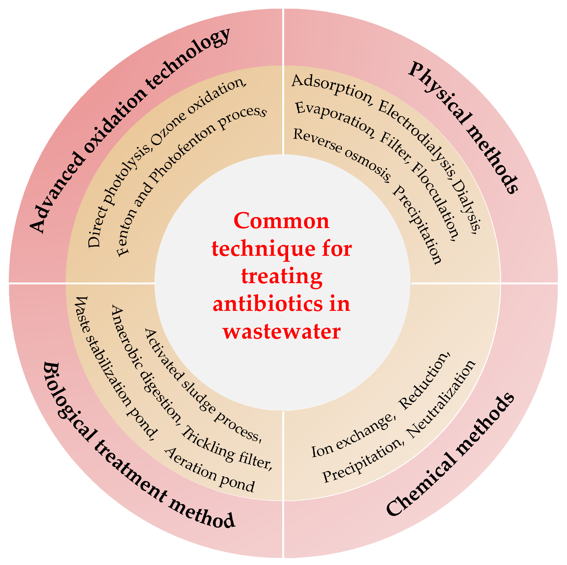
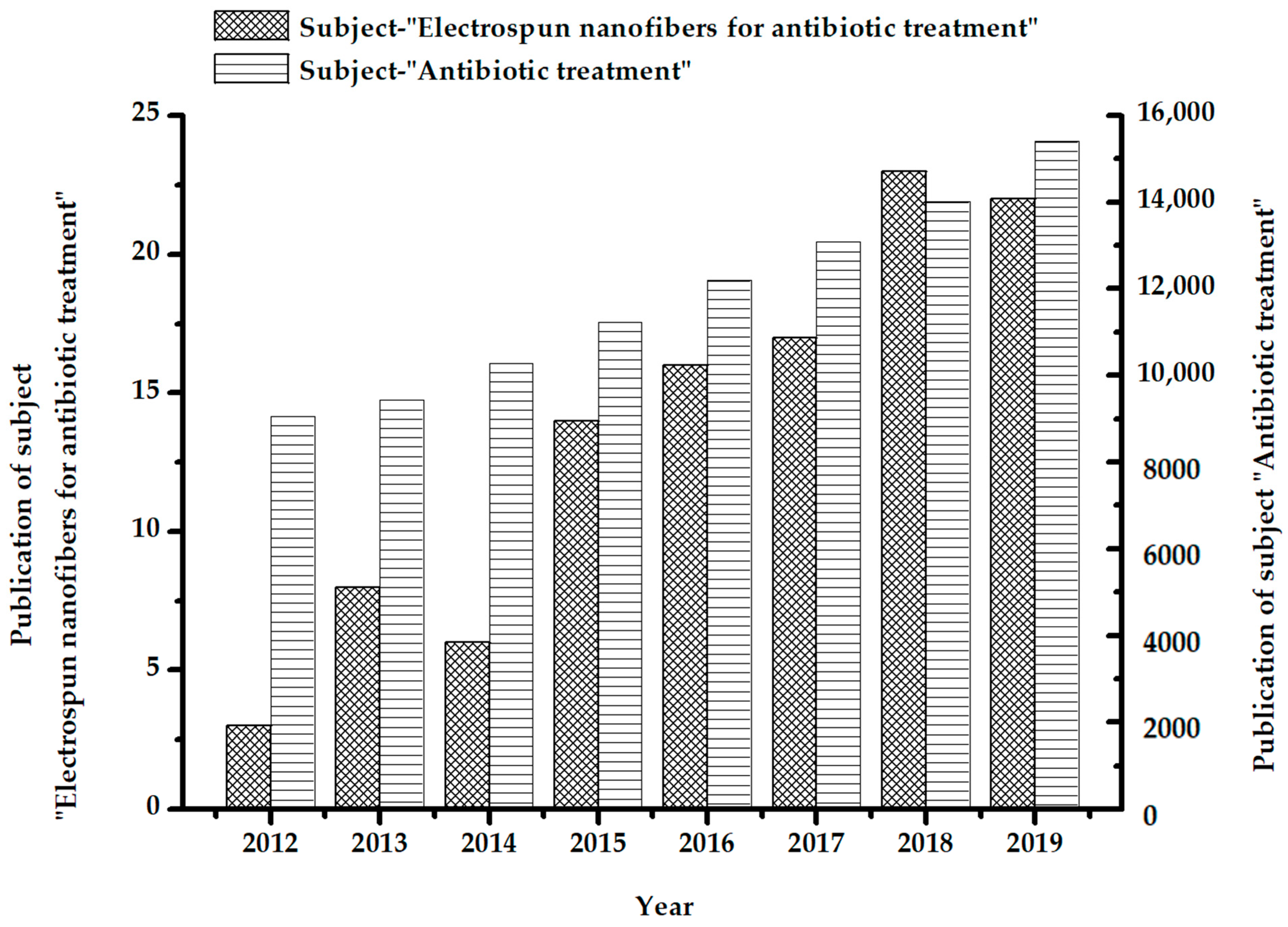
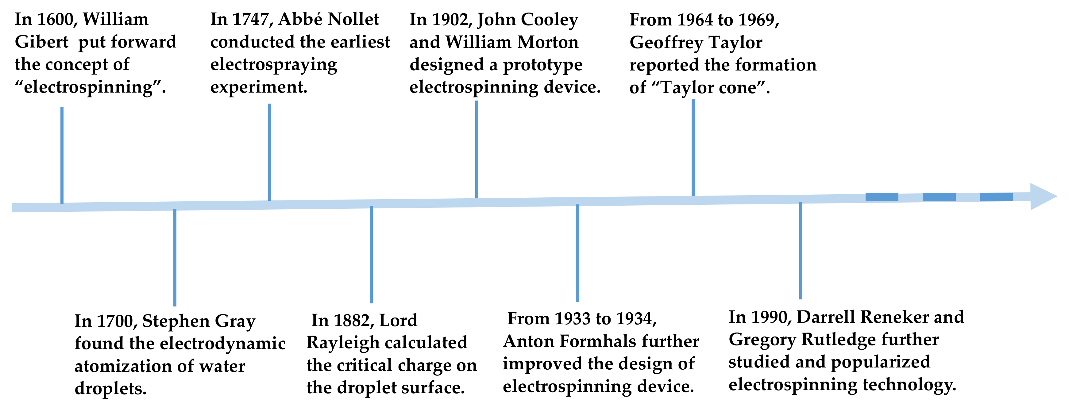
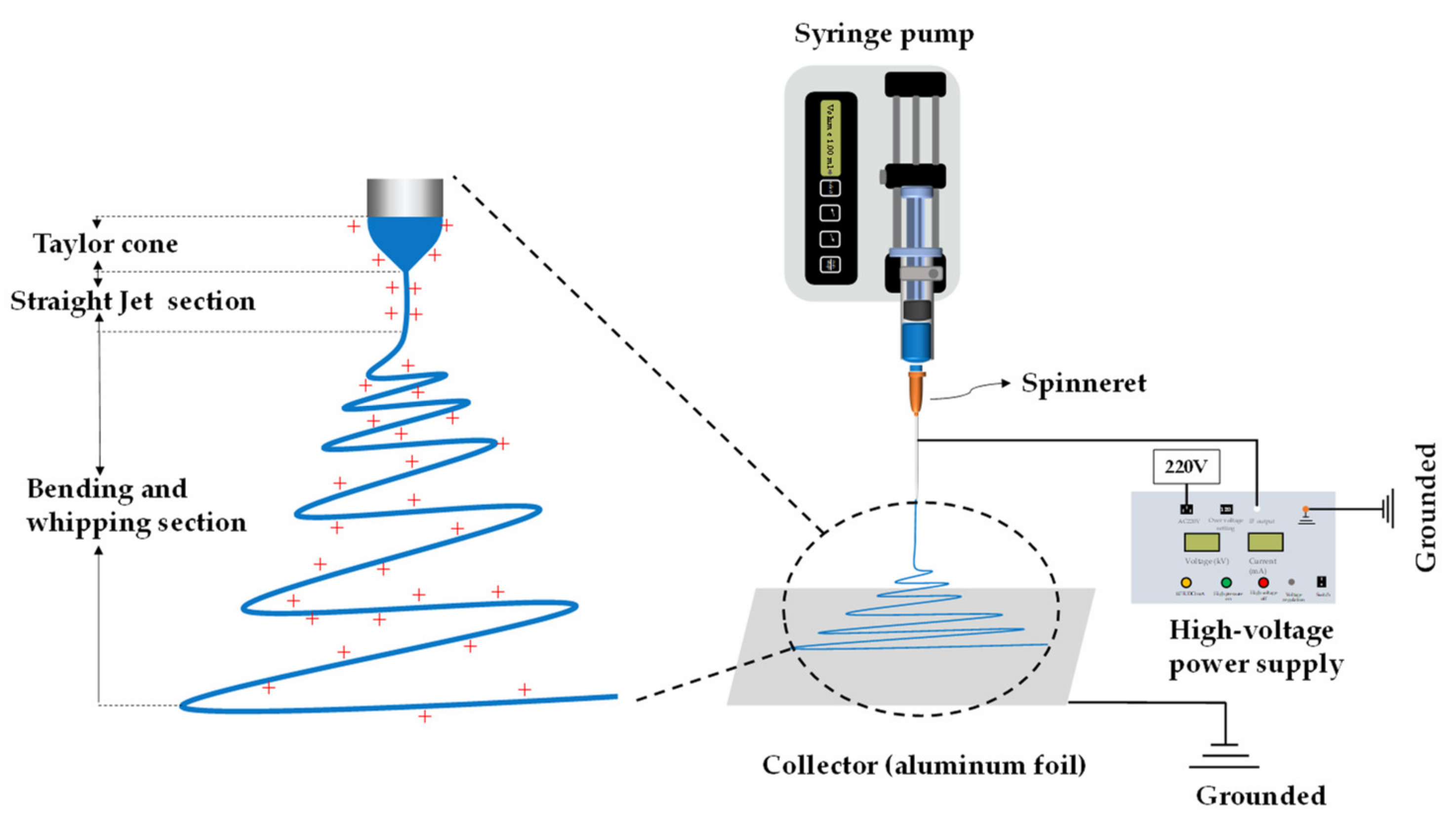
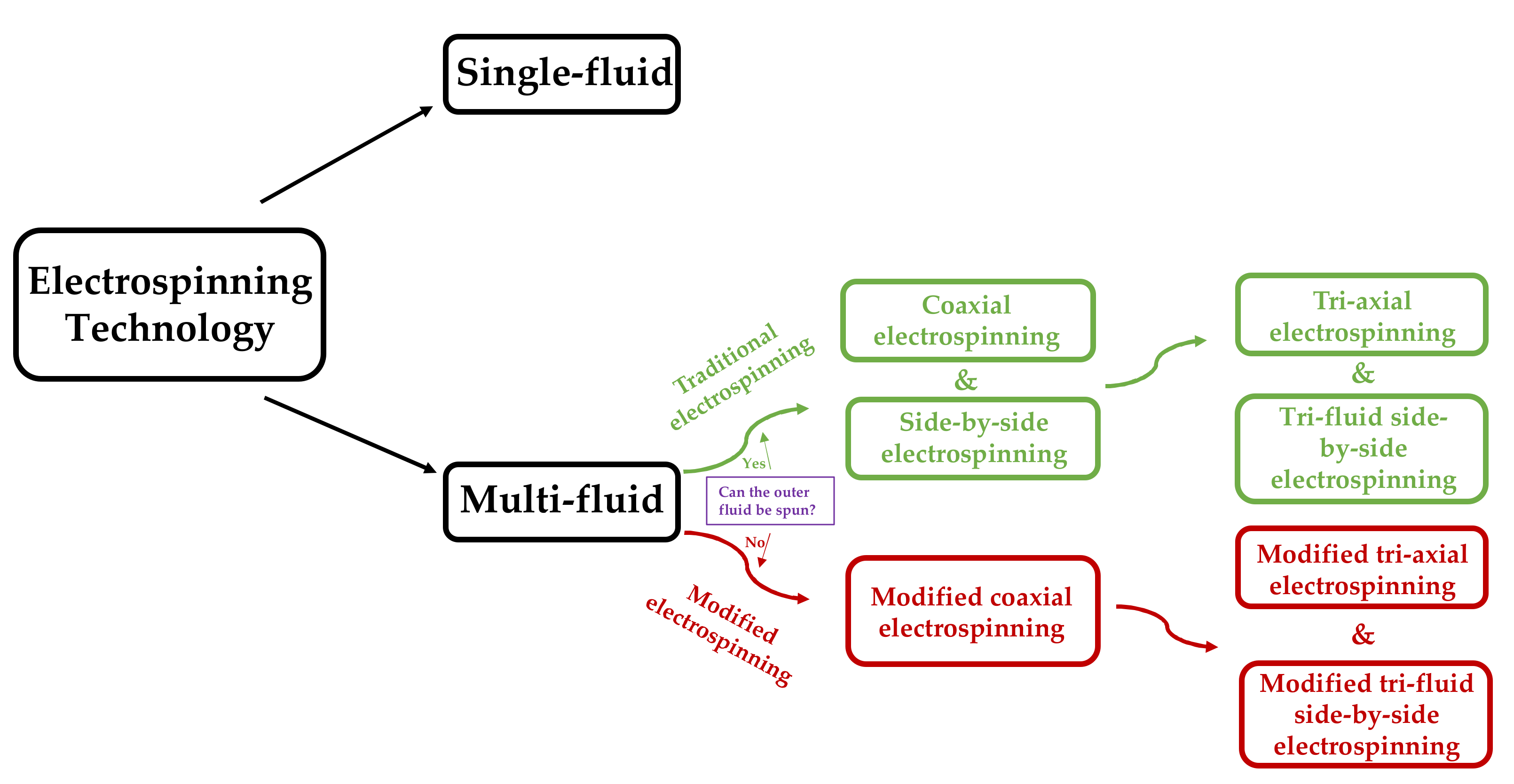
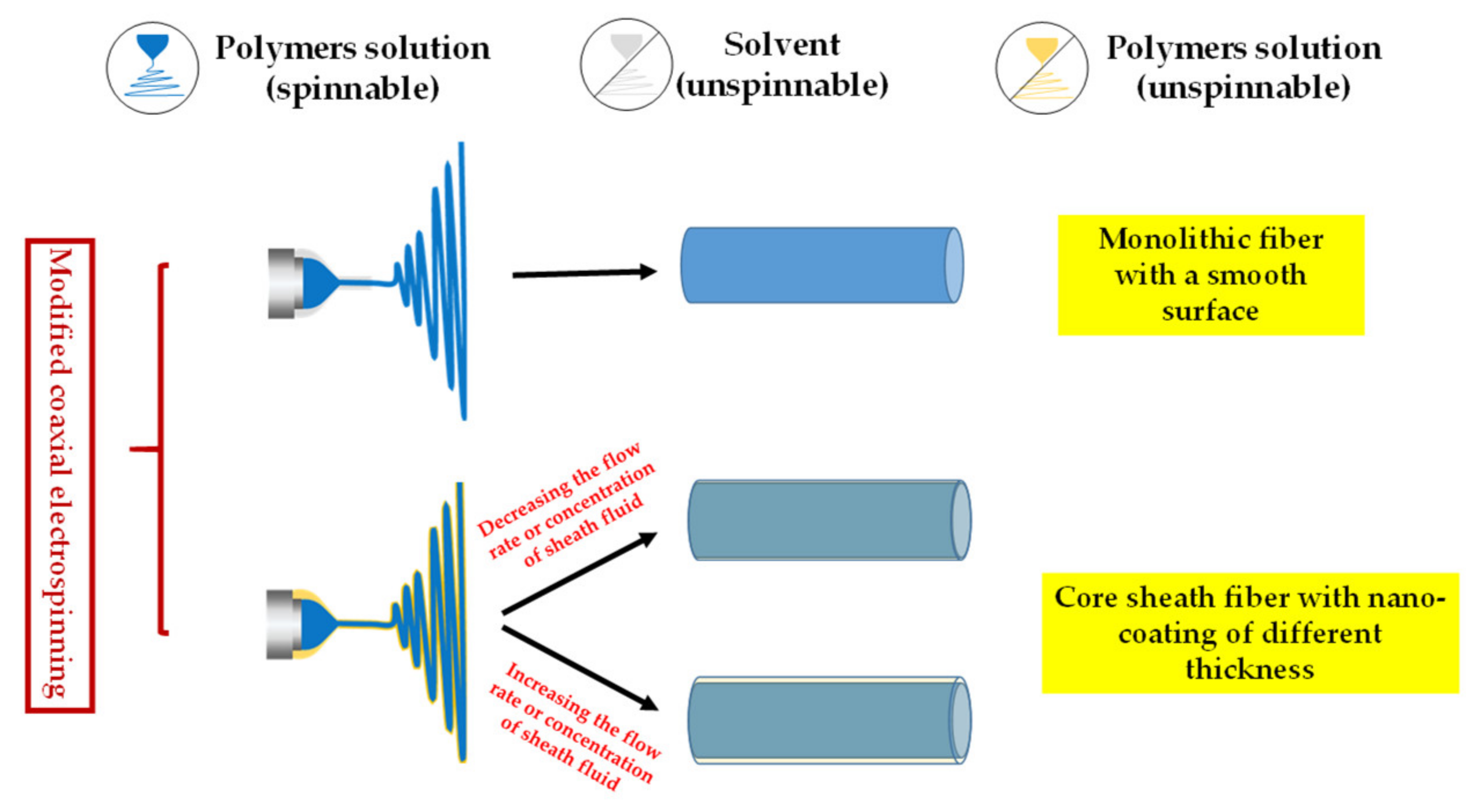
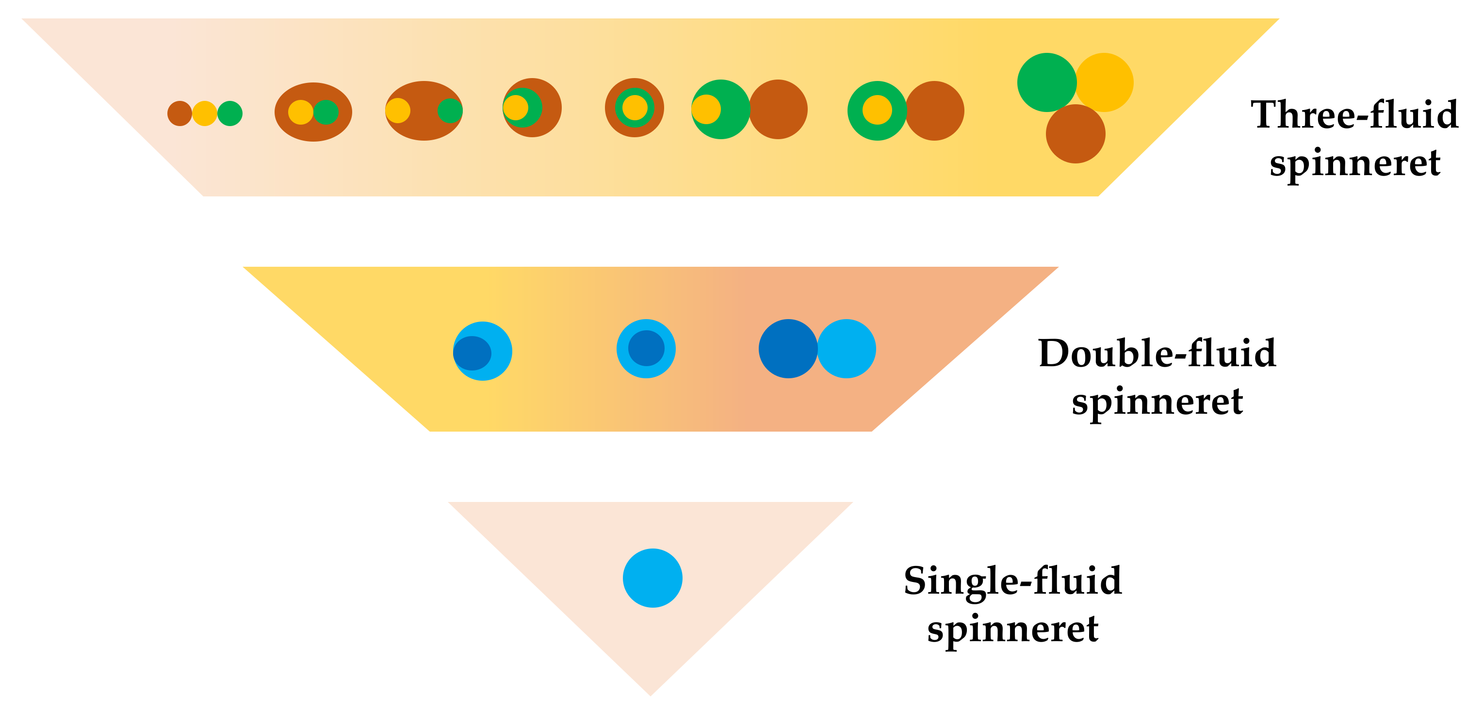
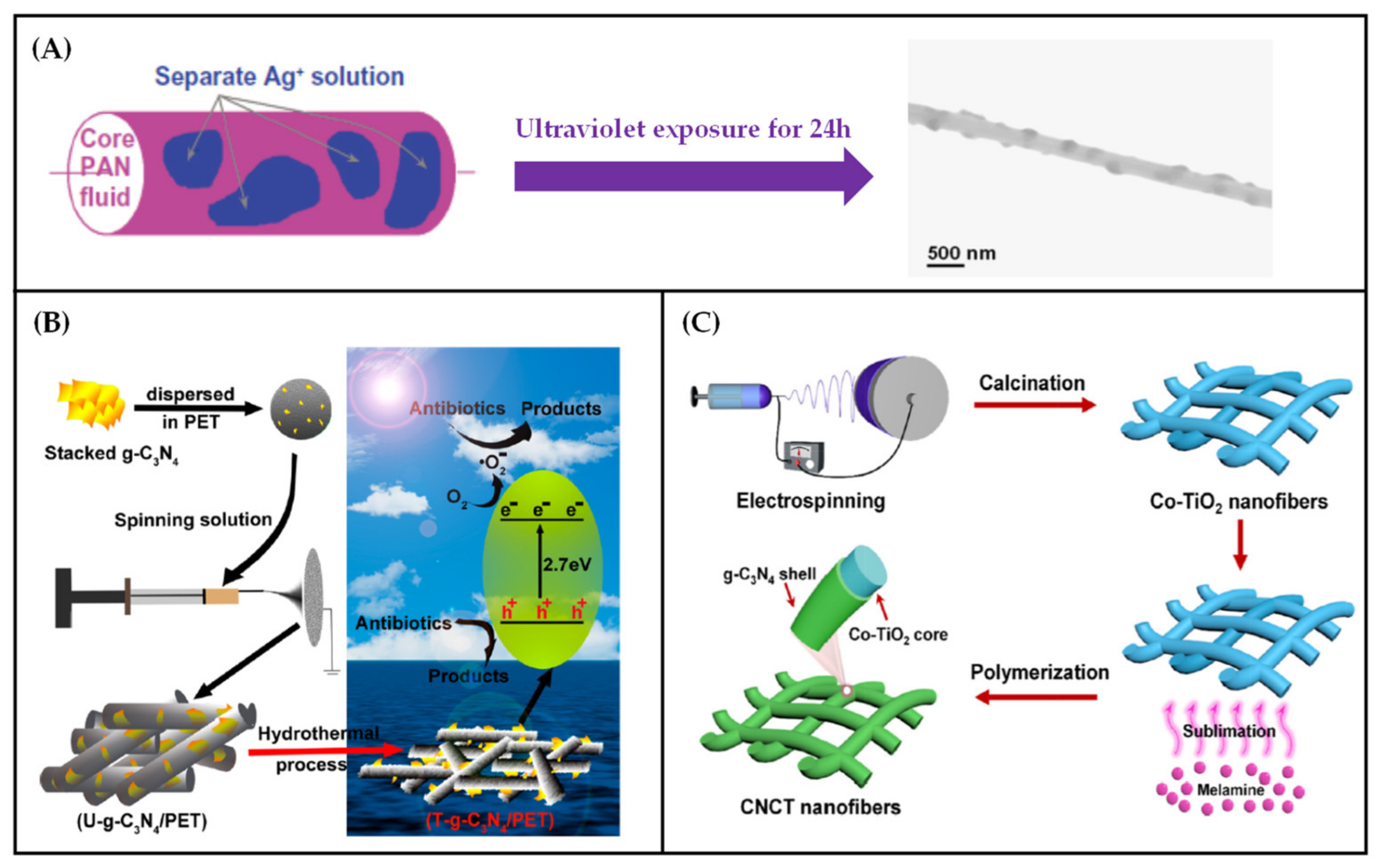
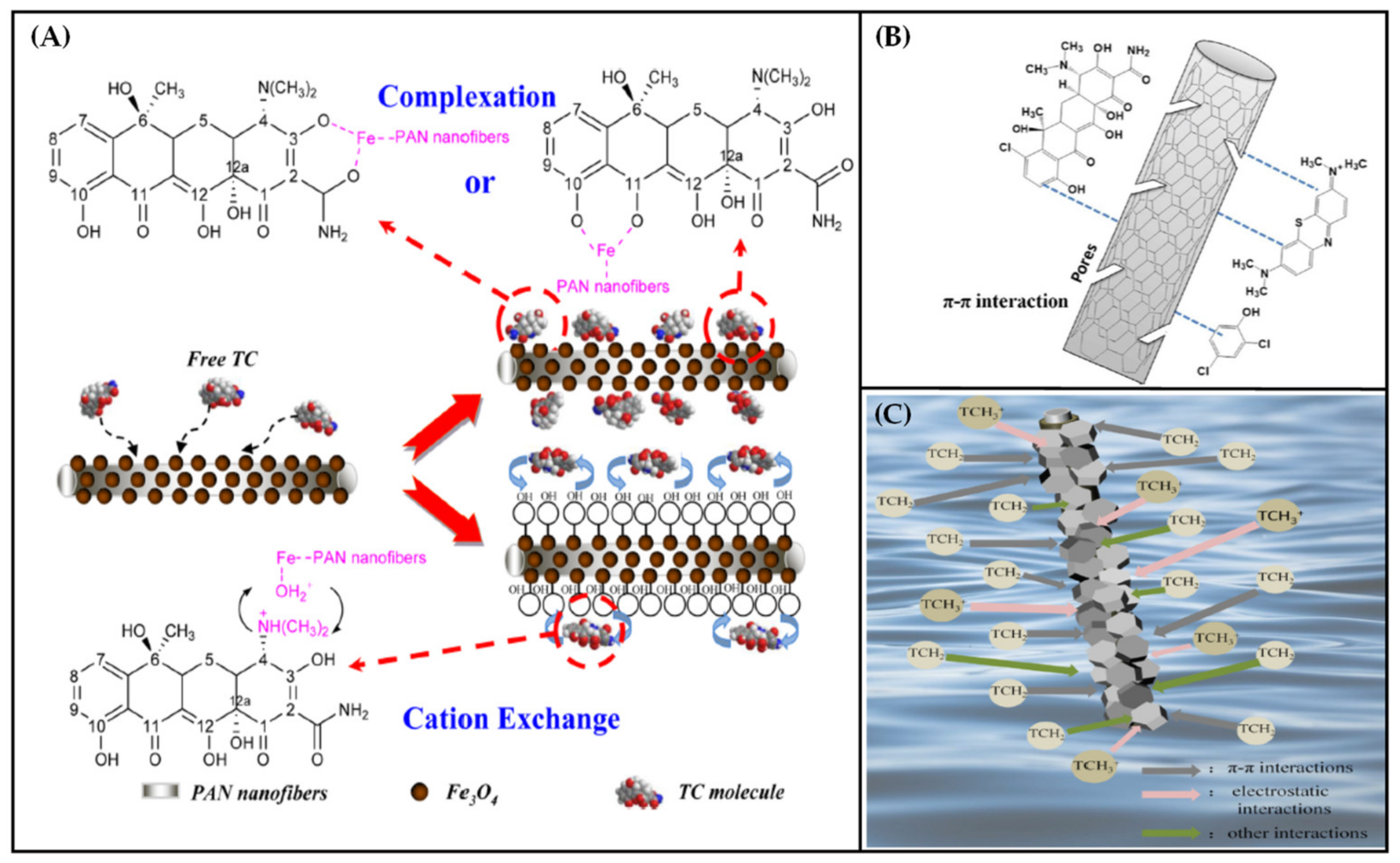
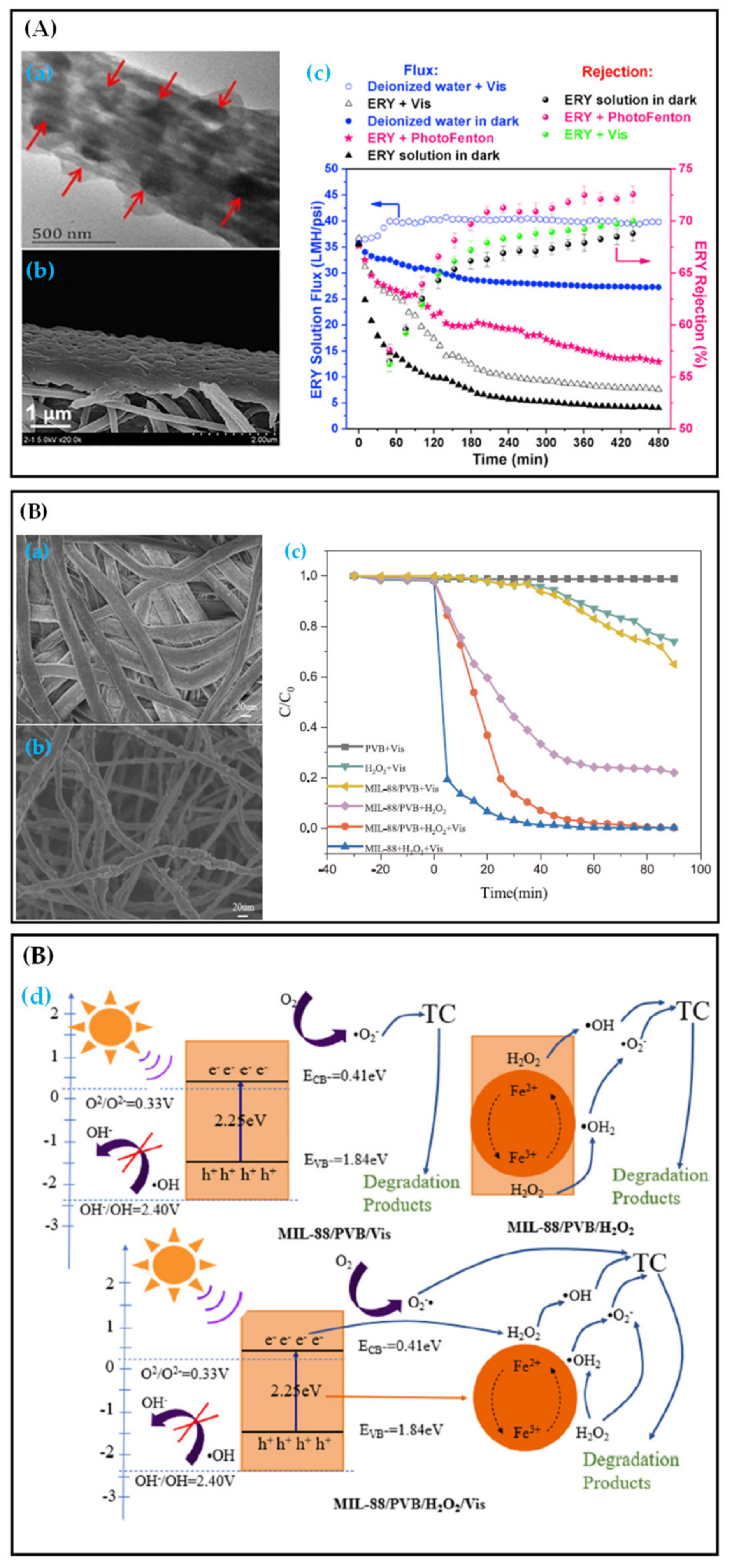
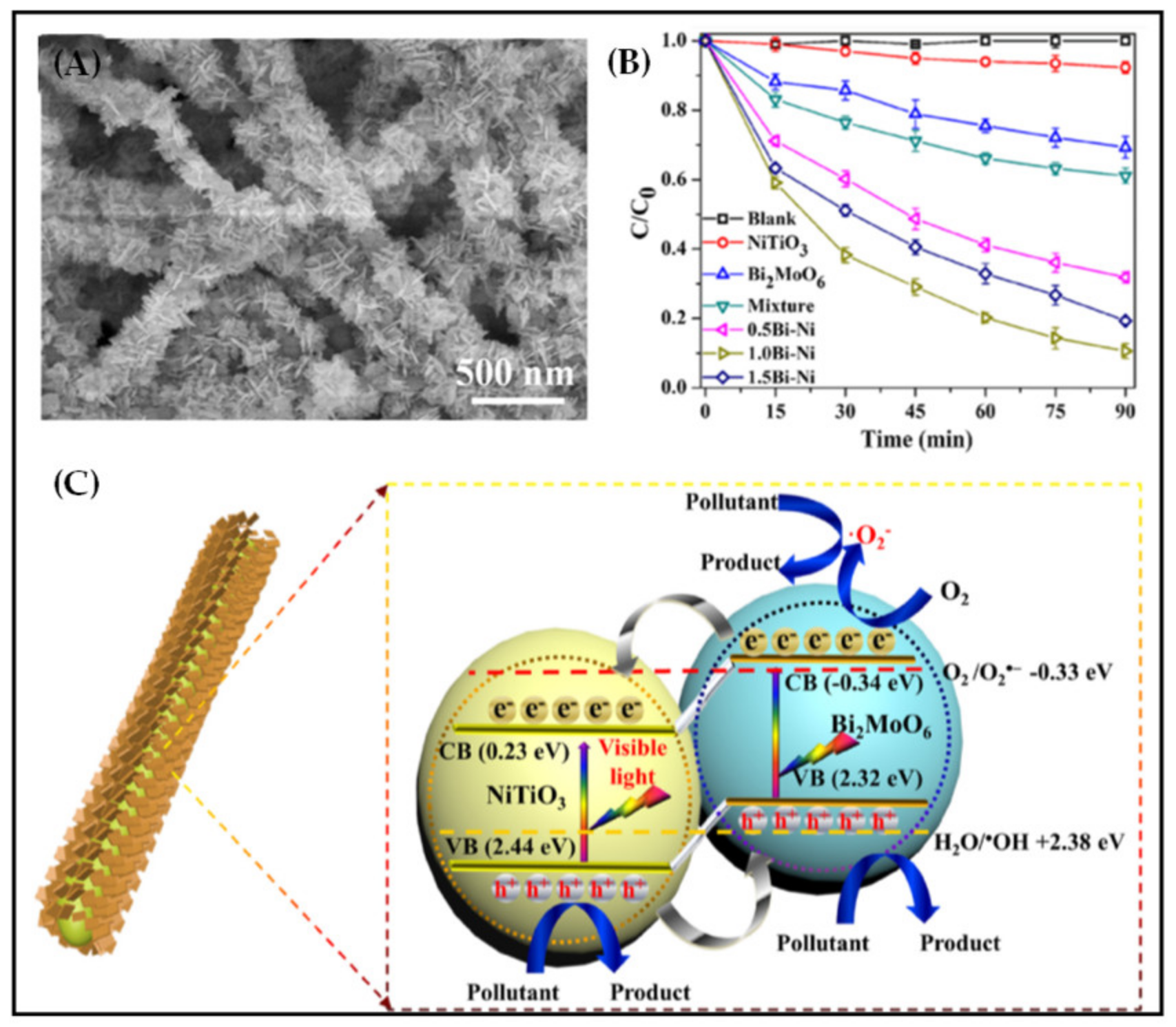
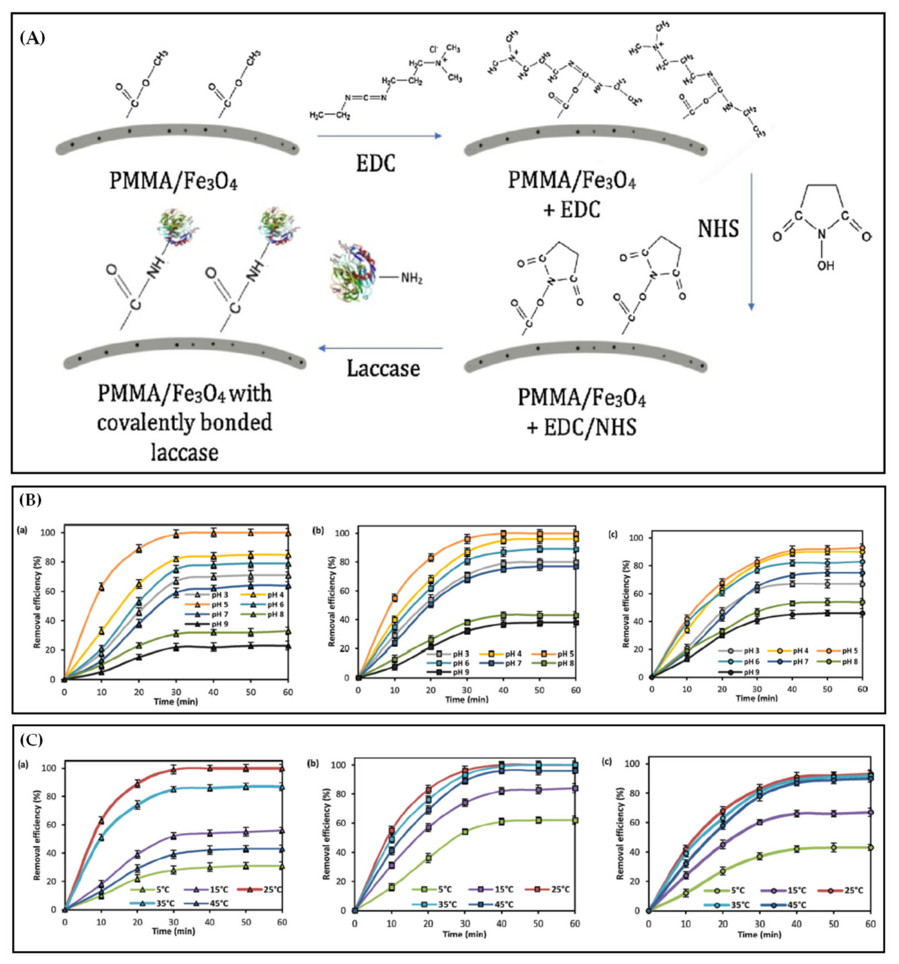
Table 1.
Classification and some physicochemical properties of common antibiotics.
| Classification | Stands for Antibiotics (CAS Number) | Molecular Formula | Solubility (mg/L) | Dissociation Constant pK a | Predicted Critical Effect Concentration (ng/L) b |
|---|---|---|---|---|---|
| Aminoglycosides | Gentamicin (1403-66-3) | C21H43N5O7 | 1 × 10⁵ | 9.0 | 1.8 × 10⁸ |
| β-Lactam | Amoxicillin (26787-78-0) | C16H19N3O5S | 3.43 × 10³ (25 °C, in water) | 3.2, 11.7 | 1.9 × 10¹⁴ |
| Carbenicillin (4697-36-3) | C17H18N2O6S | 451 | |||
| Oxacillin (66-79-5) | C19H19N3O5S | 13.9 | 2.72 | ||
| Piperacillin (61477-96-1) | C23H27N5O7S | 119 | 350,026 | ||
| Phenoxypenicillin (87-08-1) | C16H18N2O5S | 240 (pH = 1.8, in water) | 2.79 | 31,117 | |
| Chloramphenicol | Chloramphenicol (56-75-7) | C11H12Cl2N2O5 | 2500 (25 °C, in water) | 8.1 × 10⁶ | |
| Fluoroquinolones | Ciprofloxacin (85721-33-1) | C17H18FN3O3 | 30,000 (20 °C, in water) | 6.09 | 1.9 × 10⁷ |
| Danofloxacin (112398-08-0) | C19H20FN3O3 | ||||
| Enoxacin (74011-58-8) | C15H17FN4O3 | 3430 | |||
| Enrofloxacin (93106-60-6) | C19H22FN3O3 | >53.9 | |||
| Levofloxacin (100986-85-4) | C18H20FN3O4 | >54.2 | 6.25 | 1.5 × 10⁷ | |
| Norfloxacin (70458-96-7) | C16H18FN3O3 | 280 (25 °C, in water) | 6.34, 8.75 | 6.4 × 10⁶ | |
| Ofloxacin (82419-36-1) | C18H20FN3O4 | 1.08 × 10⁴ (25 °C, in water) | 5.97, 9.28 | 2.7 × 10⁷ | |
| Sarafloxacin (98105-99-8) | C20H17F2N3O3 | 1.14 × 10³ (25 °C, in water) | 5.6, 8.2 | ||
| Glycopeptides | Vancomycin (1404-90-6) | C66H75Cl2N9O24 | 225 | 2.6, 7.2, 8.6, 9.6, 10.5, 11.7 | 1.5 × 10⁸ |
| Lincosamides | Clindamycin (18323-44-9) | C18H33ClN2O5S | 30.61 (25 °C, in water) | 131,513 | |
| Lincomycin (154-21-2) | C18H34N2O6S | 927 (25 °C, in water) | 7.6 | ||
| Macrolides | Clarithromycin (81103-11-9) | C38H69NO13 | 1.693 (25 °C, in water) | 8.99 | 7267 |
| Erythromycin-H2O (67733-56-6) | C37H69NO14 | ||||
| Oleandomycin (3922-90-5) | C35H61NO12 | 16 (25 °C, in water) | 8.84 | ||
| Roxithromycin (80214-83-1) | C41H76N2O15 | 0.0189 (25 °C) | 324,384 | ||
| Spiramycin (8025-81-8) | C43H74N2O14 | Slightly soluble in water | 7.88, 9.28 | ||
| Tylosin (1401-69-0) | C46H77NO17 | 5000 (25 °C, in water) | 7.73 | ||
| Quinolones | Flumequine (42835-25-6) | C14H12FNO3 | 2.19 × 10³ (25 °C, in water) | 6.5 | |
| Nalidixic Acid (389-08-2) | C12H12N2O3 | 100 (23 °C) | 8.6 | ||
| Oxolinic Acid (14698-29-4) | C13H11NO5 | ||||
| Pefloxacin (70458-92-3) | C17H20FN3O3 | 1.14 × 10⁴ (25 °C) | |||
| Pipemidic Acid (51940-44-4) | C14H17N5O3 | 322 (25 °C) | |||
| Rifamycins | Rifamycin (6998-60-3) | C37H47NO12 | Insoluble | 1.8 | |
| Sulfonamides | Sulfamethoxazole (723-46-6) | C10H11N3O3S | 610 (37 °C, in water) | 1.6, 5.7 | 9.8 × 10⁷ |
| Sulfamethazine (57-68-1) | C12H14N4O2S | 1.5 × 10³ (29 °C, in water), 1.92 × 10³ (37 °C, in water) | 2.07, 7.49 | ||
| N4-Acetylsulfamethazine (100-90-3) | C14H16N4O3S | ||||
| Sulfadimethoxine (122-11-2) | C12H14N4O4S | 343 | |||
| Sulfamethoxypyridazine (80-35-3) | C11H12N4O3S | ||||
| Sulfapyridine (144-83-2) | C11H11N3O2S | 268 (25 °C) | 8.43 | ||
| Sulfasalazine (599-79-1) | C18H14N4O5S | 13 (25 °C, in water) | 2.3, 6.5 | ||
| Sulfasoxazole (127-69-5) | C11H13N3O3S | 300 (37 °C, in water, pH = 4.5) | 5 | ||
| Sulfathiazole (72-14-0) | C9H9N3O2S2 | 373 (25 °C, in water) | 2.2, 7.24 | ||
| Tetracyclines | Chlortetracycline (57-62-5) | C22H23ClN2O8 | 2.4 × 10⁷ | ||
| Doxycycline (564-25-0) | C22H24N2O8 | 3.5, 7.7, 9.5 | 8 × 10⁷ | ||
| Oxytetracycline (79-57-2) | C22H24N2O9 | 313 (25 °C, in water) | 3.27, 9.5 | 9.9 × 10⁹ | |
| Tetracycline (60-54-8) | C22H24N2O8 | 231 (25 °C, in water) | 3.3 | 6.7 × 10⁷ |
a The data come from the web of https://pubchem.ncbi.nlm.nih.gov and the literature of Gothwal et al. [18] and Fick et al. [29]. b The predicted critical effect concentration indicates that the concentration of antibiotics reaches a specific concentration after being dissolved in water, and the biological concentrate extracted from the water allows the drug concentration in fish plasma to reach a stable state equal to the concentration of a drug in human plasma.
Table 2.
Effect of three parameters on the morphology of electrospun fiber membrane.
| System parameters | Polymer molecular weight | When the molecular weight is large, the prepared fiber presents a straight line without beads and a huge diameter. |
| Polymer solution concentration | An appropriate large concentration is conducive to the formation of defect-free linear fibers; excessively large concentration makes it difficult to form fibers | |
| Polymer solution conductivity | When the electrical conductivity increases, the fiber diameter decreases, and bead-free fiber is easily formed; excessively high electrical conductivity reduces the uniformity of the fiber diameter distribution, and normal electrospinning is not possible | |
| Dielectric constant | Within a specific range, the larger the dielectric constant of the same solvent, the smaller diameter of the fiber; an excessively high dielectric constant affects the jet stability | |
| Surface tension | Appropriate reduction of surface tension is conducive to the formation of smooth fibers | |
| Viscosity | Appropriately increasing the viscosity will help to form uniform bead-free fibers, but the fiber diameter will increase; extremely large viscosity results in the formation of bead-like fibers and clogging, making it challenging to perform spinning; extremely small viscosity will easily cause electrospraying | |
| Solvent | High solubility is conducive to the formation of fibers with good morphology; proper volatility is conducive to the spinning process and the construction of bead-free fibers | |
| Process parameters | Applied voltage | In the proper range, the higher the voltage, the more conducive to the formation of uniform fibers with a small diameter; when the voltage is extremely high or low, the fiber diameter increases, resulting in uneven fiber diameter distribution. |
| Fluid flow rate | The flow rate increases, the fiber diameter increases, and a bead-like fiber is easily formed. | |
| Receiving distance | Within a specific range, the smaller the receiving distance, the smaller diameter of the fiber; when the receiving distance is extremely short, the fiber diameter will increase instead. | |
| Diameter of spinneret | When the spinneret diameter is small, the diameter of the fiber is small. | |
| Environmental parameters | Temperature | Within a specific range, the temperature increases, and the fiber diameter decreases. |
| Humidity | Bead-like fibers are easily produced under high humidity. |
Table 3.
Preparation technology and parameters of partially electrospun functional fiber membranes for antibiotic removal.
Table 3.
Preparation technology and parameters of partially electrospun functional fiber membranes for antibiotic removal.
| Types of Polymers | Pretreatment Technology | Post-Treatment Technology | Effect on Antibiotic Removal | Reference |
|---|---|---|---|---|
| Polylactic acid | Doping TiO2 into PLA solution (Acetone/DMF = 3/2 v/v) | The fibers were deposited on fiberglass supports to prepare fiberglass fabric plain woven-type membrane, fiberglass mat-type membrane and fiberglass fabric one-fold edge-type membrane | After photocatalytic 30 min, AC was almost completely removed in aqueous solution, and the removal effect of fiberglass fabric plain woven-type membrane was the best | [12] |
| Polysulfone | Mixing TiO2/AgNPs composite particles into PSF solution (DMF/NMP = 7/3 v/v) | Polyamide active coating was formed on the membrane surface by interfacial polymerization | The permeability of TC resistance gene in the membrane was less than 9% | [14] |
| Polyethylene terephthalate | Dispersing g-C3N4 into the PET solution (HFIP) | After heat treating the PET fibers in alkaline aqueous solution in 65 °C for 1.5 h, g-C3N4 was exposed to the surface of PET and transformed from deactivation to reappearance | Under sunlight, the photocatalytic activity for the degradation of antibiotics such as SQX and SD was high, and the photodegradation rate of SQX reached 100% (pH = 5) in 2.5 h | [124] |
| Polyvinylpyrrolidone | Putting TiO2 gel into PVP solution (ethanol) | g-C3N4 nano-sheath was formed on the fiber surfaces by in-situ thermal polymerization | The photodegradation rate of TC was as high as 90.8% in 60 min, and the inactivation of Escherichia coli was 6 log after visible light irradiation on 90 min | [125] |
| Polyethylene glycol, Polyethylene terephthalate | Adding PEG into the mixed solution of g-C3N4 and PET (HFIP) | The fiber membrane was soaked in a water bath at 60 °C for 24 h, and the porous fiber was obtained by removing PEG | Under visible light, the degradation efficiency of SQX reached 100% in 2 h | [127] |
| Polyvinyl alcohol | Adding 20% urea to PVA solution (water) | The PVA fibers were immersed in FeCl3 aqueous solution for Fe3+ complexation and then using NaBH4 solution to reduce Fe3+, ZVI NPs was synthesized in situ and immobilized, and then freeze-dried | The adsorption equilibrium of STZ was reached in 570 min, and the electrocatalysis degradation of STZ reached 100% in 5 min | [128] |
Table 4.
Comparison of adsorption conditions and effects of different electrospun functional fiber membranes on various antibiotics.
Table 4.
Comparison of adsorption conditions and effects of different electrospun functional fiber membranes on various antibiotics.
| Categories of Electrospun Functional Fiber Membranes | Types of Antibiotics | Best Adsorption Conditions | Maximum Adsorption Capacity | Reusability | Reference |
|---|---|---|---|---|---|
| PVA/SiO2 fiber membrane loaded with MOF | CAP | CAP concentration: 100 mg/L, Temperature: 298 K, Equilibrium time: 180 min, Oscillation rate: 200 r/min | 79.5 mg/g | [13] | |
| PAN/Fe3O4 nanofiber membrane | TC | TC concentration: 22 mg/L, Temperature: 298 K, pH = 6 ± 0.05, Equilibrium time: 72 h, Oscillation rate: 150 r/min | 257.07 mg/g | Desorption agent: 0.01 M, NaOH solution, Adsorption efficiency: Only 2.72−3.61% decrease in five cycles | [130] |
| PI-based carbon nanofiber membrane | TC | TC concentration: 20 mg/L, Temperature: 298 K, pH = 4–7, Equilibrium time: 19 h | 146.63 mg/g | Desorption agent: 1 M, NaOH solution, Adsorption efficiency: 9.3% decrease after five cycles | [131] |
| PAN/ZIF-8 nanofiber membrane | TC | TC concentration: 50 mg/L, Temperature: 298 K, pH = 5, Equilibrium time: 72 h | 478.18 mg/g | Desorption agent: absolute ethanol, Adsorption efficiency: keeping not less than 85% of the initial adsorption capacity after five cycles | [132] |
| MMT/CA nanofiber membrane | CIP | CIP concentration: 10 mg/L, Temperature: 303 K, pH = 6, Equilibrium time: 60 min, Oscillation rate: 100 r/min | 13.8 mg/g | Desorption agent: 10 mM NaOH solution, Adsorption efficiency: 5% decrease in CIP removal in each cycle | [149] |
| GO/PVDF nanofiber membrane | TC | TC concentration: 200 mg/L, Temperature: 298 K, pH = 3.8–4.2, Equilibrium time: 60 min | 17.92 mg/g | [164] | |
| PI/β-CD nanofiber membrane | TC | TC concentration: 20 mg/L, Temperature: 298 K, pH = 6, Equilibrium time: 1000 min, Oscillation rate: 120 r/min | 543.48 mg/g | Desorption agent: 1 M NaOH, Adsorption efficiency: 11.51% decrease after five cycles | [165] |
| PAN carbon nanofiber membrane | CIP | CIP concentration: 10 mg/L, Temperature: 298 K, pH = 6.2, Equilibrium time: 8 h, Oscillation rate: 150 r/min | 0.68 mmol/g | [166] | |
| CS/PVA nanofiber membrane (crosslinked by glutaraldehyde) | TC | TC concentration: 100 mg/L, Temperature: 297 ± 2 K, pH = 6, Oscillation rate: 120 r/min | 102 mg/g | [167] | |
| Mondia white roots/PVA nanofiber membrane | Inosine, sulfamethoxazole, lidocaine, amitriptyline hydrochloride, prednisone, isoniazid, dexamethasone, ritonavir, efavirenz, fluconazole | Drug concentration: 0.5 mg/L, Temperature: 308 K, pH = 5, Balance time: 120 min, Oscillation rate: 125 r/min, | 75–320 mg/g | [168] | |
| Mesoporous protein/PVA nanofiber membrane | Sulfonamides and veterinary drugs | Sulfonamides- Drug concentration: 0.1 mg/L, Temperature: 310 K, pH = 5.5, Equilibrium time: 60 min, veterinary drugs-, Drug concentration: 0.1 mg/L, Temperature: 300 K, pH = 5.5, Equilibrium time: 60 min, Oscillation rate: 125 r/min | The removal efficiency of sulfonamides: 86.9–95.9%, The removal efficiency of veterinary drugs: 32.62–100.73 mg/g | [169] |
Publisher’s Note: MDPI stays neutral with regard to jurisdictional claims in published maps and institutional affiliations. |
© 2021 by the authors. Licensee MDPI, Basel, Switzerland. This article is an open access article distributed under the terms and conditions of the Creative Commons Attribution (CC BY) license (http://creativecommons.org/licenses/by/4.0/).
Share and Cite
MDPI and ACS Style
Zhao, K.; Kang, S.-X.; Yang, Y.-Y.; Yu, D.-G. Electrospun Functional Nanofiber Membrane for Antibiotic Removal in Water: Review. Polymers 2021, 13, 226. https://0-doi-org.brum.beds.ac.uk/10.3390/polym13020226
AMA Style
Zhao K, Kang S-X, Yang Y-Y, Yu D-G. Electrospun Functional Nanofiber Membrane for Antibiotic Removal in Water: Review. Polymers. 2021; 13(2):226. https://0-doi-org.brum.beds.ac.uk/10.3390/polym13020226
Chicago/Turabian StyleZhao, Kun, Shi-Xiong Kang, Yao-Yao Yang, and Deng-Guang Yu. 2021. "Electrospun Functional Nanofiber Membrane for Antibiotic Removal in Water: Review" Polymers 13, no. 2: 226. https://0-doi-org.brum.beds.ac.uk/10.3390/polym13020226
Note that from the first issue of 2016, this journal uses article numbers instead of page numbers. See further details here.