1. Introduction
Cardiovascular diseases represent one of the main causes of death in the world. About 8.5 million people worldwide have diseased blood vessels that must be replaced with vascular grafts [
1,
2]. Currently, commercially available synthetic vascular grafts are made of several non-biodegradable materials such as polytetrafluoroethylene (PTFE) and polyethylene terephthalate (PET) [
3]. However, their performance is inefficient in replacing small diameter vessels (<6 mm) due to their limited long-term patency with only 32% success after 2 years [
4,
5] caused by thrombogenic events [
3], intimal hyperplasia [
6,
7] and/or atherosclerosis [
8], triggering several acute or chronic inflammatory responses [
6].
To overcome the limitations of the currently available alternatives, the tissue-engineering field is a strategy for the implantation of a hemodynamic-responsive conduit able to maintain long-term patency [
9]. Therefore, biodegradable synthetic polymers (BSPs) are promising platforms for the fabrication of 3D structures [
10]. In this sense, tissue regeneration will only proceed via a unique interplay between stem cells and the scaffold, determined by specific 3D architectures with given mechanical properties, and the presence of bioactive molecules [
4].
Nevertheless, the lack of surface bioactivity of most BSPs limits their further applicability to promote cell adhesion, growth, and proliferation [
6]. For instance, although different tissue engineered vascular grafts (TEVGs) made of BSPs, such as PLA—polylactic acid, PCL—polycaprolactone, PGA—polyglycolic acid, PU—polyurethane, PVA—polyvinvyl acetate, and even PS (polystirene), have been reported to be tested on preclinical animal models, none of them have reached clinical trials as they lack the required features to overcome the current limitations [
11,
12].
To address this issue, polymers have been functionalized with CO
2 and NO
2 plasma to improve hydrophilicity and protein adsorption as well as conjugate bioactive molecules [
13] such as adhesive peptides (e.g., CAG, RGD, YIGSR) [
14,
15] and antithrombogenic agents (e.g., PEG, PEI, heparin) [
16,
17,
18]. Other strategies include blends with natural polymers such as gelatin, chitosan, and cellulose [
19]. Despite the successful results in terms of surface bioactivity enhancement, functionalization processes usually involve highly sophisticated and costly procedures and equipment [
20] as well as volatile fluorine-toxic solvents (e.g., trifluoroethanol, trifluoracetic acid, hexafluoroisopropanol, among others) to achieve dissolution of blends, which has given rise to several environmental and health concerns due to their end-of-life products [
21].
On the other hand, for complex tissues such as blood vessels, esophagus, tracheae, stomach, intestine, bladder and urethra, there is a hierarchical structure comprised of a diverse population of already differentiated cells. Under physiological conditions, the maturation of cells from a single precursor begins with a small population of self-replicating tissue-specific stem cells that will eventually not only differentiate towards a specific lineage, but to a hierarchy of progressively differentiated cells [
22]. In the specific case of the cardiovascular system, such a complex structure is given by the native blood vessel ECM, which is composed of three main layers with different features and a composition capable of maintaining vascular homeostasis through the development of different cell phenotypes by means of surface bioactivity, topography, and microstructure [
23].
These complex interactions explain the reason for preclinical models on TEVGs showing that nearly 14% of them fail in early stages either in the peri-implantation stages or within the first months, and 35% of them report patency loss or need of removal before the beginning of the tissue remodeling. In this sense, although the graft has been successfully implanted, the substrate is not suitable for tissue remodeling either due to thrombogenesis, generation of exacerbated acute inflammatory responses, or due to lack of regeneration, caused, in both cases, due to limited cell infiltration and interaction given by the BSP properties and scaffold microstructure [
4].
Scaffold customization to mimic complex tissues and organs with unique 3D and hierarchical organizations is therefore a major challenge for successful tissue repair. This is especially true when there is a natural interface separating different layers within the native tissue where different types of cells (e.g., endothelial and other functional cells) organize themselves in unique 3D patterns [
24]. For instance, for blood vessels, in the innermost layer, called intima, the crosstalk of endothelial cells provides antithrombogenicity and control over muscular tone and inflammation [
9]. In contrast, the media layer and adventitia have circumferential aligned collagen and elastin microfibrils that guide the orientation of smooth muscle cells (SMC) to provide the necessary mechanical strength to maintain patency under the circulatory pressure changes [
25,
26].
In this regard, the rational design of next-generation BSP-based vascular substitutes might be based on the structural design of tubular structures incorporating physicochemical gradients of key components [
27]. Forming such 3D constructs might be achieved using additive manufacturing techniques including 3D bioprinting, inkjet printing, and electrospinning. When ECM-fibrillar-like constructs are needed, solvent-assisted methods such as electrospinning seem to be the choice mainly due to the fabrication of fibers in nano- or microscale, control of the scaffold porosity and interconnectivity, and high surfaces areas. Those features allow the cellular interaction and infiltration, as well as the mass transfer for the required nutrient supply and oxygen diffusion [
11,
28]. Electrospinning can also be implemented in conjunction with solvent-casting and particle leaching techniques to control surface topography while avoiding significant fluid leakage [
12].
Electrospinning also offers the opportunity to shape the surface topography and tailor the microstructure of scaffolds by combining the fibrillar-like structure with highly interconnected porous hydrogels fabricated using particle leaching techniques [
29]. Here, we aimed at developing a scaffold with tunable microarchitecture and physicochemical cues capable of mimicking the morphological, mechanical, and bioactive cues of the hierarchical structure of the blood vessel’s ECM. This was achieved via the rational and sequential assembly of a tri-layer system by combining solvent-casting manufacture for the first layer and electrospinning and particle leaching techniques for the second and third layer, respectively.
To fabricate an intima-like layer with the surface topography and mechanical resistance observed in native arteries, we employed oxidized PCL (as oxygen-containing functional groups (OCFG) have demonstrated increased biochemical reactivity) deposited on a microgrooved mold manufactured via photolithography. Then, the second and third layers (resembling media and adventitia) were PCL:salt (10%:5%) solutions co-electrospun with varying PCL:gelatin weight ratios (75%:25% and 95%:5%
w/w) over a rotating mandrel. The polymer blends were obtained via a novel single-desolvation-based method. Gelatin was included to provide controlled biodegradability rates and the possibility of conjugating arginine-glysine-aspartic acid (RGD) resemble motifs, which have been proven useful to allow cellular integration and reduce inflammatory responses [
24]. Moreover, to introduce topological cues over the layers, crosslinked glutaraldehyde was implemented followed by salt particle leaching. Correct functionalization of polymers was verified via Fourier transfer infrared spectroscopy (FTIR), TGA, and DSC.
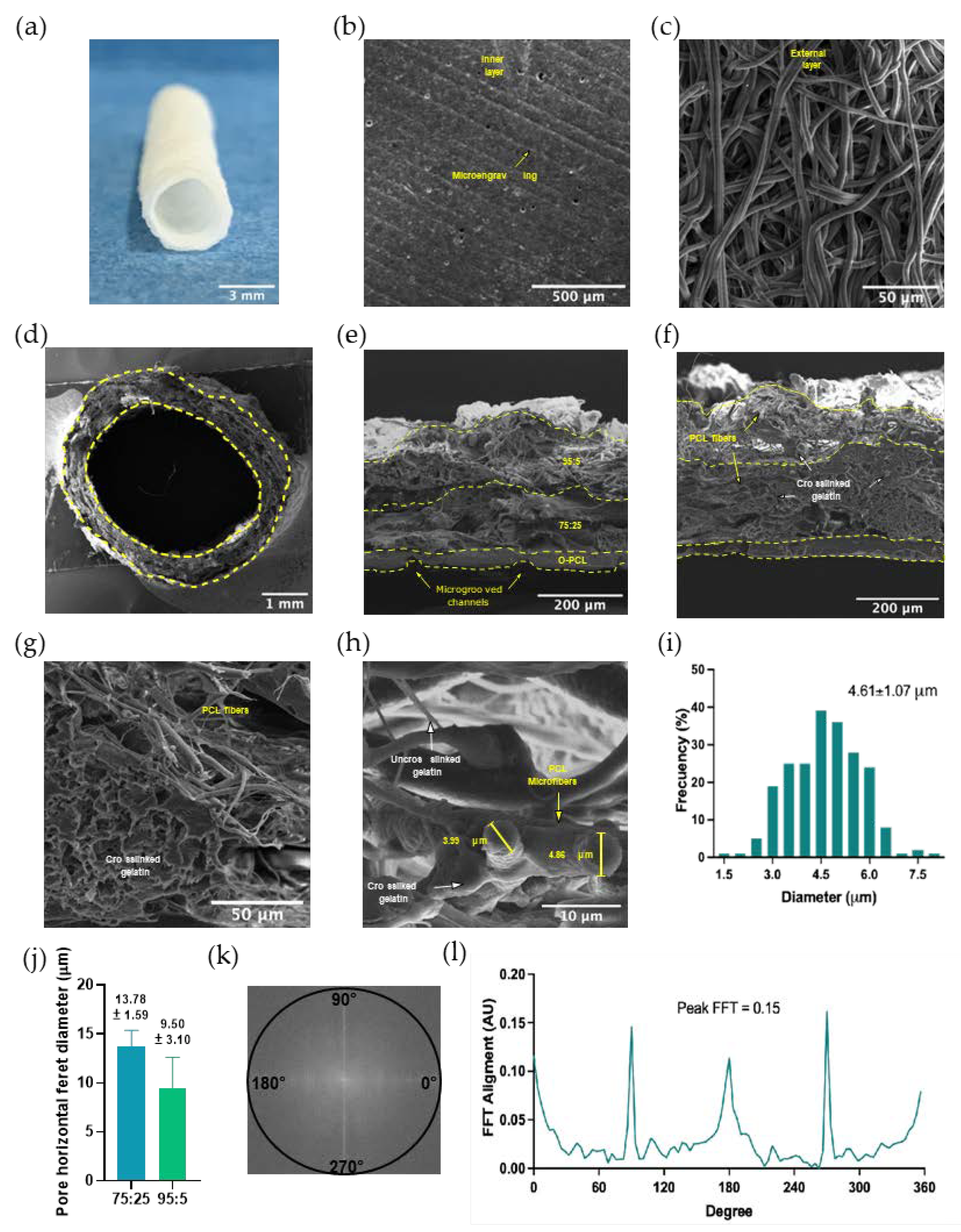
Thus, the manufactured trilayer tubular scaffold exhibited a microgrooved continuous innermost layer, followed by a semi-oriented and porous structure intermediate layer, and finally an outermost layer with prominent fibrillar structures. As proof-of-concept of the feasibility of the engineered scaffold as a vascular graft, protein adsorption capacity, fibroblast cell-seeding, and the release of intracellular reactive oxygen species (ROS) were studied after PCL functionalization confirmation.
2. Materials and Methods
2.1. Materials
Polycaprolactone (PCL, average molecular weight, 80 kDa), chloroform (99.8%), sulfuric acid (H2SO4, 98%), potassium permanganate (KMnO4, 95%), citric acid (C6H8O7, 99.5%), phosphate buffer saline (PBS), thiazolyl blue tetrazolium bromide (MTT), dimethyl sulfoxide (DMSO, 99%), Dulbecco’s modified Eagle’s medium (DMEM), hydrofluoric acid (48%), Formalin (10%) and Triton X-100 were purchased from Sigma-Aldrich (St. Louis, MO, USA). Type B gelatin was obtained from Químicos Campota (Bogotá, Colombia). Vero cells (CCL-81) and L929 murine fibroblasts (CCL-1) were acquired from ATCC®. A lactate dehydrogenase (LDH) kit was acquired from Roche (Basel, Switzerland). Fetal bovine serum (FBS) was obtained from Biowest (Riverside, MO, USA) and DAPI (4′,6-diamidino-2-phenylindole) and Alexa Fluor 594TM phalloidin were obtained from Thermo Fisher Scientific (Waltham, MA, USA).
2.2. PCL Oxidation
PCL backbone chemical modification was carried out via oxidation with KMnO
4 to generate oxygen-containing functional groups (OCFG) as described previously by Sabino [
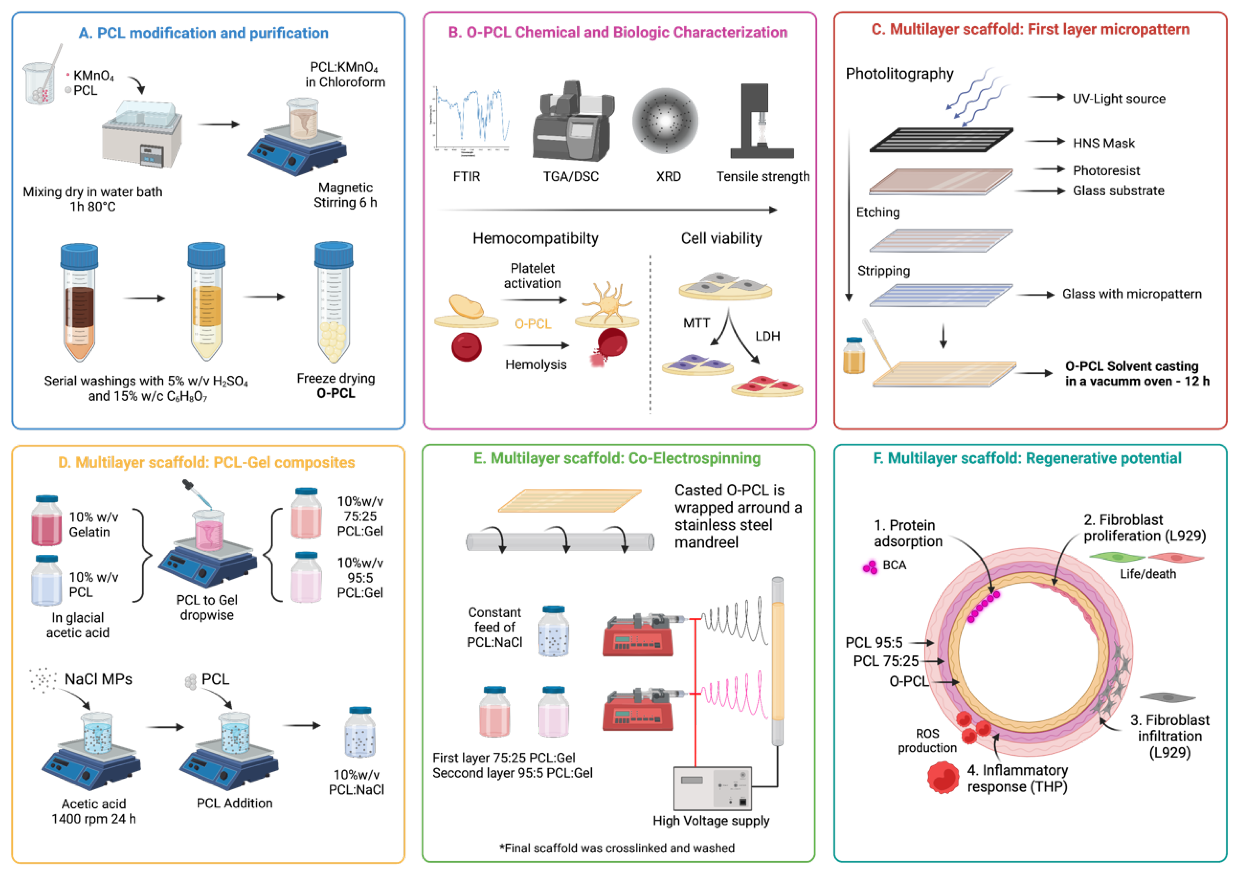
30] including some modifications (
Figure 1A). PCL and KMnO
4 in a 1:5 molar ratio were heated at 80 °C in a water bath for 30 min and mixed with a glass rod in the dark every 5 min. The blend was dissolved in chloroform (10%
w/v) for 2 h at 50 °C and oxidation was allowed for another 12 h. To remove undesired reaction products (i.e., manganese dioxide—MnO
2) and the remnant KMnO
4, the oxidized PCL (O-PCL) solution was washed three times using an excess amount of aqueous H
2SO
4 2%
w/v by vigorously vortexing with intermediate centrifugations at 4000 rpm for 5 min to remove the supernatants. Finally, three additional washes with aqueous C
6H
8O
7 15%
w/v were performed as previously described and the yellowish chloroform solution was freeze dried for 24 h to obtain purified O-PCL (
Figure S1).
2.3. O-PCL Physicochemical Characterization
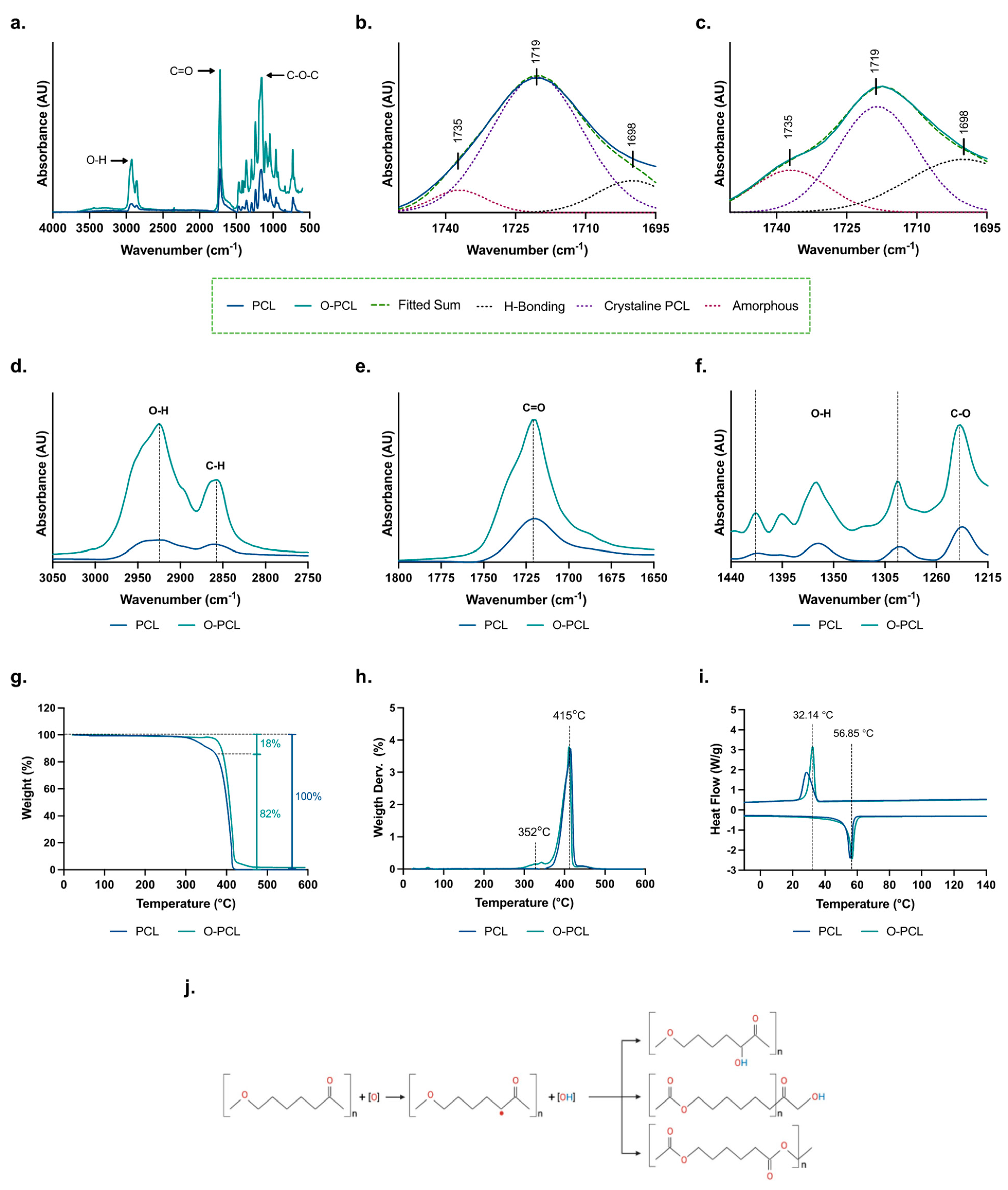
PCL oxidation was confirmed via identification of an increase in the OCFG with Fourier transform infrared spectroscopy (FTIR) and calorimetric analysis. Infrared spectra were recorded in an Alpha II FTIR Eco-ART (Bruker Optik GmbH, Ettlingen, Germany) from 4000 to 600 cm
−1 with a spectral resolution of 2 cm
−1. The broadening of characteristic peaks of PCL were analyzed to identify backbone structural changes, and hidden peaks in the carbonyl region (1760—1694 cm
−1) were resolved based on three Gaussian-shaped absorption bands to identify changes in H-bonds between adjacent chains and amorphous and crystalline phases [
31].
To compare differences on the thermal degradation profiles that may arise from changes in the covalent bonds of the PCL backbone, a thermogravimetric (TGA) analysis was performed from 25 °C to 600 °C using a ramp of 10 °C/min (ASTM E1131) under nitrogen atmosphere (100 mL/min), in a TA Instruments Q600 thermogravimetric analyzer
® (New Castle, DE, USA). Moreover, DSC analysis was undertaken (ASTM D3418) in a TA Instruments Q2000 (New Castle, DE, USA) with a nitrogen atmosphere at a flow rate of 300 mL/min from 25 °C to 130 °C with a heating rate of 10 °C/min. To erase previous thermal history, the instrument was held in an isothermal for 5 min. The samples were cooled down to 25 °C at the same heating rate and then heated to 130 °C as described previously. Data from the first cooling and the second heating steps were recorded and plotted for their analysis (
File S1).
PCL and O-PCL X-ray diffraction (XRD) analysis was taken in a Rigaku Ultima III X-ray diffractomer (Tokio, Japan) in the Bragg-Brentano configuration. Samples with an average contact area of 25 mm
2 were placed into a bounding grid of 5 mm and exposed to a Bragg diffraction angle (2θ) sweep between 5° and 50° with a 1.5°/seg step using Kα radiation with a copper (Cu) anode of 40 kV and 40 mA. The Debye-Sherrer equation was used to estimate the apparent crystal size of the polymeric structure based on the full-width at half-maximum of the X-ray diffraction line, also known as FWHM, the wavelength of the X-ray used, which was 1.5406 nm, and the angle between the incident ray and the scattering planes. The phase content of each sample was calculated from the XRD profiles via peak deconvolution using the Materials Data Jade 9
® Software (Newtown Square, PA, USA) using Gaussian profiles as fitting methods (
File S2).
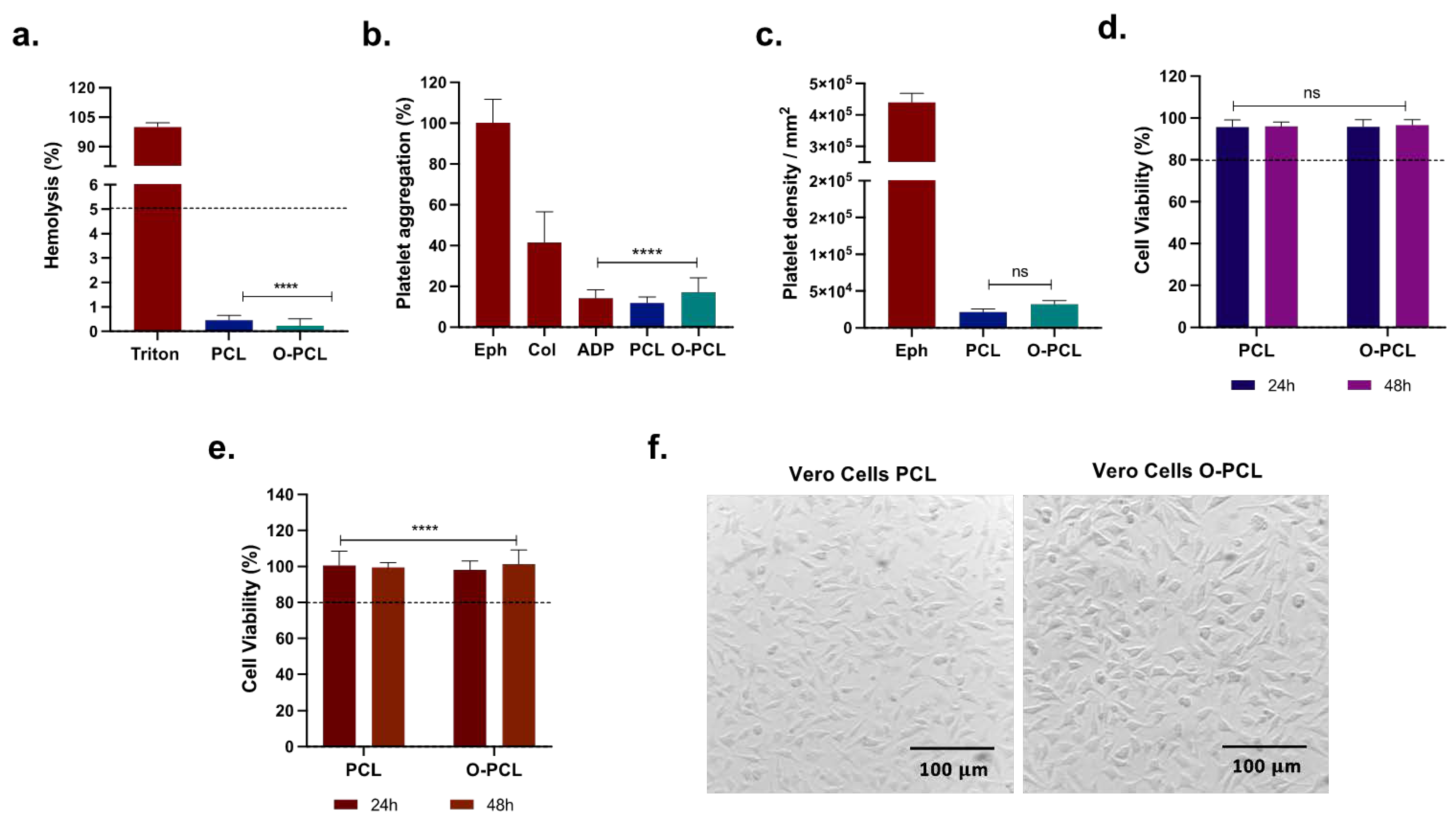
Biocompatibility
Considering that the oxidation of PCL could induce changes on the PCL cytocompatibility, hemolytic tendency, platelet aggregation, and activation capacity, biocompatibility assays were conducted following the ISO 10993 standard. The hemolysis assay was conducted using freshly drawn O+ human blood (from a healthy donor) collected in ethylenediaminetetraacetic acid (EDTA) tubes after signing an informed consent (Ethical Committee at the Universidad de Los Andes, minute number 928–2018). The anticoagulated blood was washed 5 times with 0.9% w/v NaCl solution at 1800 rpm for 5 min and diluted 1:10 in PBS 1X to obtain an initial stock of 4.25 × 10⁶ erythrocytes/µL. Rectangular samples of the material (0.3 cm2) were immersed in 100 µL of the erythrocyte solution for 1 h and 37 °C in a 96-well microplate. PBS 1X and 1% Triton X-100 were used as negative and positive controls, respectively. After incubation, the samples were removed, centrifugated at 1000 rpm for 5 min, and the supernatant absorbance was determined at 454 nm.
Platelet aggregation and activation assays were performed using freshly drawn O+ human blood (from a healthy donor) collected in sodium citrate tubes after signing the informed consent. The anticoagulated blood was centrifuged at 1000 rpm for 10 min to obtain platelet-rich plasma (PRP) and 200 µL was exposed to rectangular scaffold samples (0.3 cm
2) allowing contact for 3 min and 1 h for platelet aggregation and activation assays, respectively. After incubation, supernatants were removed, absorbance was read at 620 nm from the 3 min exposed samples, and adherent platelets from the samples incubated for 1 h were lysed with 1%
v/v Triton X-100 for 5 min. Then, LDH working solution (LDH Cytotoxicity Detection Kit) was added to the supernatant and the absorbance was recorded at 493 nm. For platelet quantification, PRP was serially diluted ten times from 3.56 × 10
5 to 6.95 × 10
2 platelets/µL to build a calibration curve. Then, absorbance from the calibration curve was fit to a linear regression model (R
2 = 0.99,
Figure S2). Finally, the number of platelets were normalized via the contact surface area (i.e., 0.3 cm
2). Epinephrine, collagen, and adenosine diphosphate were included as controls of high, medium, and low aggregation.
To verify O-PCL cytocompatibility via both metabolic activity (MTT) and membranal integrity (LDH) in epithelial-like cells, Vero cells were included. Briefly, 100 μL of a cell stock (1 × 10⁵ cells/mL) was seeded and allowed to adhere in a 96-well microplate for 24 h (37 °C, 5% CO2) in DMEM media (5% FBS, 1% P/S). Cells were then exposed directly to rectangular scaffold samples (0.3 cm2) for an additional 24 and 72 h. DMSO (10% v/v) and Triton X-100 (1% v/v) were used as positive controls for cytotoxicity in the MTT and LDH assays, respectively. For the LDH assay, the scaffold was removed and 100 µL of the cell’s supernatants was transferred to a new 96-well microplate. Then, LDH reagent solution was added according to the manufacturer instructions and the absorbance was recorded at 493 nm. For the MTT assay, cells were exposed to the MTT reagent solution and incubated for 2 h to allow formazan conversion (37 °C, 5% CO2). The formed purple crystals were dissolved with DMSO, and the absorbance was read at 595 nm.
2.4. Multilayer Scaffold Fabrication
2.4.1. Fabrication of Microgrooved First Layer
Since intima layers of blood vessels typically include a complex microarchitecture, a microgroove mold was fabricated via photolithography (
File S3) to imprint a homogeneous micropattern on the luminal layer of the scaffold (
Figure 1C). The groove width was 30 μm and the ridge height and weight between repetitive prims of 18 μm and 35 μm, respectively. This was according to porcine carotid artery histological measurements (
Figure S4). Accordingly, the first layer of the scaffold was prepared by dissolving O-PCL in chloroform (1:10
w/
v) for 1 h before placing it over the microgrooved mold (
Figures S4 and S5) in a vacuum oven at 25 °C to allow controlled solvent evaporation and the imprinting of the micropattern. The correct imprinting on the resultant casted film was analyzed via topography measurements along the surface with a profilometer in triplicate (DEKTAK 3, Bruker, Billerica, MA, USA) (
Figure S6).
2.4.2. Blends Preparation
PCL:gelatin blends at 75:25 and 95:5
w/w were prepared using a novel single-desolvation method. Briefly, PCL and gelatin at 10%
w/v were dissolved separately in chloroform:glacial acetic acid (3:8
v/v) and 80%
v/v aqueous acetic acid at 50 °C under continuous magnetic stirring. The obtained solutions were mixed by incorporating the dissolved PCL dropwise into the gelatin solution (1 mL/min) at 50 °C under vigorous stirring. This was to allow the controlled gelatin agglomeration through a pH increase for the restoration of gelatin charges through the carboxyl groups (-COOH). In addition, a PCL:salt (1:1
w/w) blend was prepared with NaCl microsized crystals dispersed in chloroform (1:10
w/v) for 24 h at room temperature via high velocity stirring before the addition and dissolution of PCL to achieve a homogeneous solution [
32].
2.4.3. Electrospinning
For the fabrication of the hierarchical porous tubular scaffolds, PCL:gelatin at two different ratios (i.e., 75:25 and 95:5
w/w) and PCL:salt blends were co-electrospun over a first layer of micropatterned [
27] O-PCL wrapped on a 3.2 mm stainless steel cylindrical mandrel to form a second and a third layer. Before the electrospinning, the O-PCL was sealed onto the mandrel via immersion in glacial acetic acid for 5 s with the microgrooved channels aligned to the mandrel. Each blend solution was co-electrospun through a 16-gauge needle at a flow rate of 1 mL/h using a Cole-Parmer 78-8180C (Vernon Hills, IL, USA) syringe pump, with a needle-to-tip distance of 16 cm and continuous mandrel rotation at 300 rpm for 1 h per layer. The voltage was maintained at 6 kV for the second layer (75:25
w/w) and 8 kV for the third layer (95:5
w/w) to control fiber deposition and obtain a hierarchical fibrillar porosity gradient [
27].
After the electrospinning process, the mandrel containing the scaffold was placed in a glutaraldehyde (25% v/v) bath and maintained overnight under continuous rocking movements (10 rpm) using a waving shaker (LabCompanion, Seoul, Korea) to allow gelatin crosslinking at room temperature. The crosslinked scaffold was then removed wet from the mandrel and washed five times with aqueous glutamic acid (5% v/v supplemented with 1–8% hydrochloride acid) to remove glutaraldehyde excess every 1 h. Then, a salt leaching process was performed by rinsing the scaffold in distilled water for 12 h at room temperature under gentle agitation at 10 rpm using a waving shaker and stored in PBS 1X at 4 °C until further use.
2.5. Scanning Electron Microscopy
Scanning electron microscopy (SEM) inspection was performed in a JSM-6490LV
® microscope (JEOL USA Inc., Peabody, MA, USA) with a 10 kV accelerating voltage. Before the examination, samples were cryofractured on liquid nitrogen with perpendicular and parallel cuts with respect to their length, fixed onto aluminum plates with carbon tape, and coated with a thin layer of gold using Vacuum Desk IV Denton Vacuum, Moorestown, NJ, USA) apparatus. SEM micrographs were processed with Fiji
® and ImageJ
® software packages (version 5.2.0, National Institutes of Health, Bethesda, MD, USA) to analyze the average fiber diameter, size distribution, and relative fiber alignment of electrospun mats by quantifying the diameter of 200 randomly selected fibers in three SEM images at 500× magnification. The relative fiber alignment of the electrospun layers was then analyzed with fast Fourier transform (FFT) [
33] by translating optical information into the frequency domain and extracting the radial summing of the pixel intensities in oval projection discretized into 100 points aided by the oval profile plugin. The results were normalized with respect to the minimum value in the dataset and plotted in arbitrary units ranging from 0 to 0.15 [
29]. Values above 0.065 units together with two larger peaks observed at 90° and 270° were interpreted as aligned fibers [
34].
2.6. Protein Adsorption Capacity
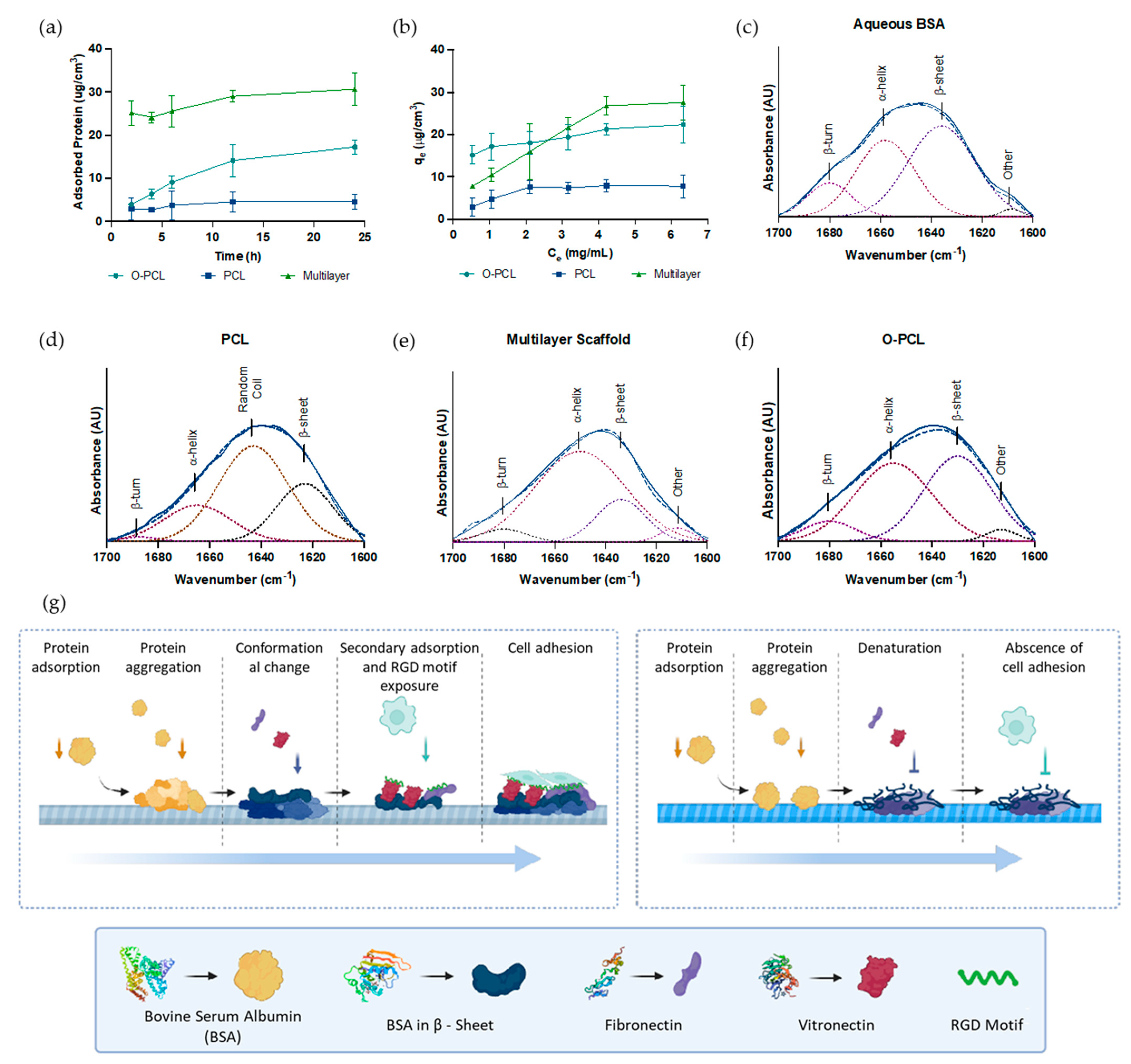
As PCL oxidation and PCL:gelatin blending were developed here to improve surface bioactivity of the multilayered scaffold, we hypothesized that protein adsorption would be promoted by the OCFG [
35]. Therefore, protein adsorption capacity was evaluated by immersing samples of PCL, O-PCL, and the multilayered scaffold in supplemented DMEM cell culture media (5%
v/v FBS) for 2, 4, 6, 12, and 24 h at 37 °C. After incubation, the samples were transferred to a new 96-well microplate and exposed to 50 μL of aqueous 1%
w/v SDS for 30 min at 37 °C. Then, the concentration of protein released in the supernatants was quantified using a bicinchoninic acid (BCA) assay kit (Quanti-Pro, Sigma Aldrich). A bovine serum albumin (BSA) standard curve (
Figure S7) labeled BSA with rhodamine B (RhB) (1:1 equivalent ratio). Briefly, a working solution of EDC/NHS and RhB was prepared for 15 min at 37 °C to pre-activate the RhB carboxyl-terminal groups before reaction with 1 mg/mL of aqueous BSA for 24 h at room temperature under constant magnetic stirring. Then, the labeled BSA was dialyzed using a Slide-A-Lyzer™ Dialysis Cassette of 7K MWCO (Thermo Scientific™, Waltham, MA, USA) to remove excess RhB. Finally, labeled proteins were conjugated to samples for 24 h at 37 °C, washed five times with PBS 1X, and imaged with an Olympus FV1000 Confocal Microscope (Tokyo, Japan) under a 20× objective and 559 nm laser excitation. Z-stacks were collected at 10× magnification and stacked from 50 adjacent Z-planes with a stack separation of 2 μm. The spatial distribution of the adsorbed proteins was assessed with the aid of Fiji
® and ImageJ
® software packages.
2.7. Secondary Conformational Changes of Adsorbed Proteins
Secondary conformational changes of adsorbed proteins were estimated using Gaussian deconvolution of the amide I band of the FTIR (1600–1700 cm
−1) spectra (
Section 2.3). Briefly, O-PCL, PCL and the multilayer scaffold were incubated with 1 mg/mL of BSA in PBS 1X for 24 h at 37 °C under constant agitation. After incubation, the supernatants were removed, samples were gently washed twice with PBS 1X to remove unbound BSA, followed by collecting the FTIR spectra and subtracting the corresponding baselines.
2.8. Protein Adsorption Kinetics and Isotherms
The adsorption kinetics and adsorption isotherms were measured for PCL, O-PCL, and the multilayered scaffold for six FBS concentrations in DMEM media ranging from 30% to 2.5% (
v/v) as a function of time (0 to 24 h) at 37 °C. After incubation, adsorbed proteins were quantified as described in
Section 2.7 and fit to the pseudo-first-order (PFO) and pseudo-second-order (PSO) kinetic models (
Figure S7) [
36,
37]. Experimental data were also fit to the Langmuir and Freundlich models to estimate possible adsorption mechanisms (
Figure S8) [
33]. In all cases, adsorbed proteins mass was normalized to a sample volume of 25 mm
3 for the PCL and O-PCL and 384 mm
3 for the multilayered scaffold. In all cases, the goodness of fit for the evaluated models was assessed with the correlation coefficient R
2.
2.9. Tensile Strength Test
Tubular specimens with a ring deformation area of 2.49 ± 0.03 mm2 were tested using a longitudinal tensile test (ISO 7198: 2016) at a strain rate of 50 mm/min until failure in a INSTRON 3367 (Norwood, MA, USA) before and after 24 h of protein adsorption. In addition, tensile properties of thin films of PCL and O-PCL (L= 100 mm, w = 10 mm, t = 0.156 mm) were recorded (ASTM D882) using a crosshead speed of 12.5 mm/min. Sample thicknesses were measured using a 549 Micrometer (Testing Machines Inc., Amityville, NY, USA), and a total of five samples of each specimen were tested.
2.10. In Vitro Cell Morphology and Proliferation
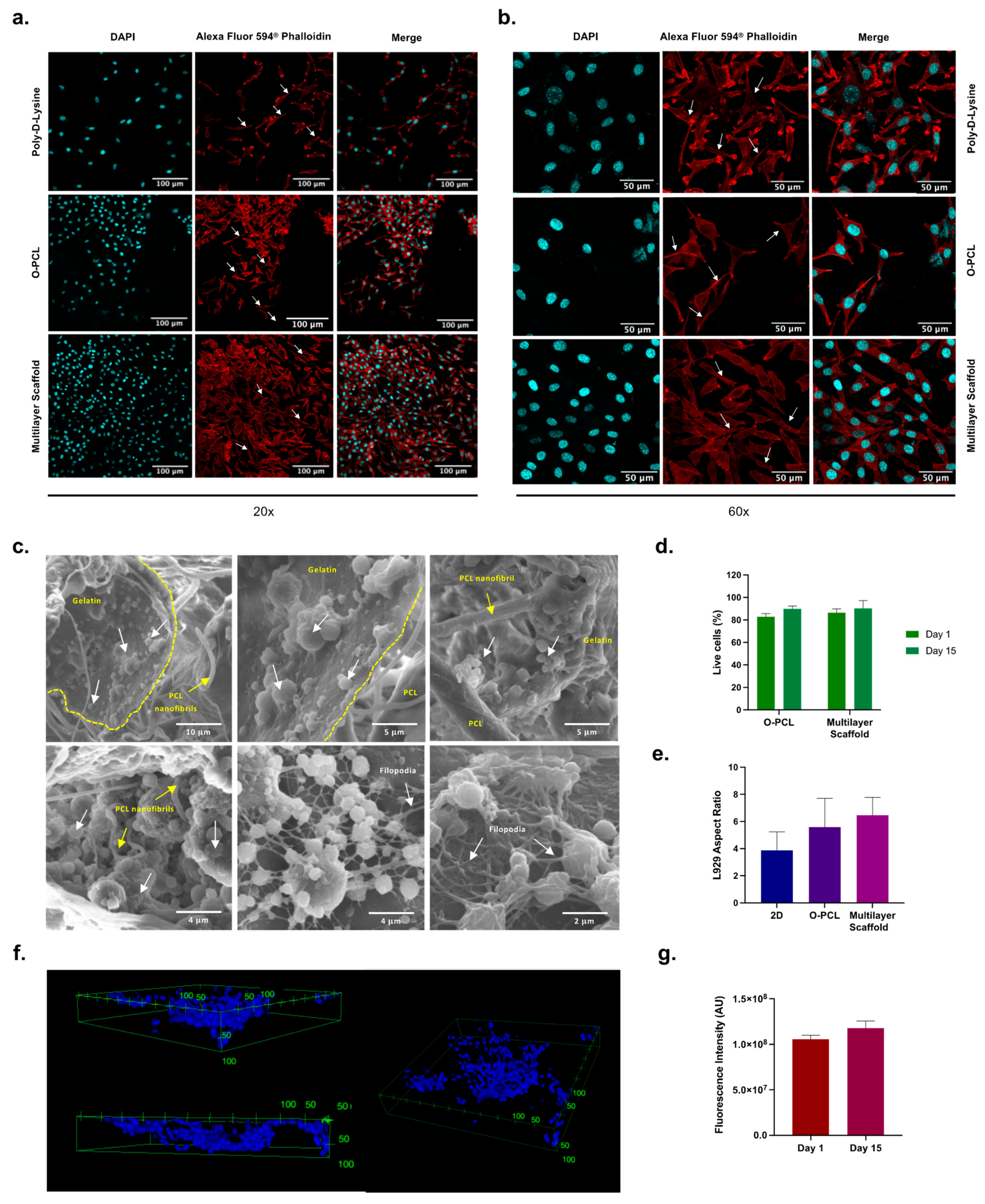
Fibroblasts play a key role in tissue regeneration due to the cell matrix deposition, helping cell colonization on the biomaterial, especially in the external layers of the blood vessels. L929 mouse fibroblasts were used to assess the cell proliferation capacity, morphology changes, and cell infiltration on the inner and the external layers of the multilayered scaffold. Cells were seeded on PCL scaffolds (4 mm × 4 mm × 1 mm) in a 24-well microplate at a cell density of 60,000 cell/sample, allowing cell adhesion for 2 h before immersion in DMEM media (10% FBS, 1% P/S). Samples were then cultured for 15 days (37 °C, 5% CO2) with daily media replacement.
After incubation, cells were fixed with 10% v/v formalin for 30 min and washed three times with PBS 1X. Subsequently, cell membranes were permeated with 0.25% w/v Triton X-100 in PBS 1X for 30 min and washed three times with PBS 1X. Finally, the samples were exposed to a working solution of Alexa Fluor 594TM phalloidin (1:400) and DAPI (1:1000) in PBS 1X, incubated at room temperature for 1 h, washed five times with PBS 1X, and immediately imaged with a confocal microscope (Olympus FLU 1000, Tokyo, Japan) using 488 nm and 358 nm laser excitations. Three images at 20× and 60× magnifications were stacked from 50 adjacent Z-planes with a stack separation of 2 μm. Two-dimensional cell cultures (10,000 cells/cm2) over a 18 mm glass slide coated with Poly-D-Lysine (PLL; Sigma, P4832, 0.01% aqueous solution) were included as reference for cells morphology and as positive control of the cell culture incubated for 24 h. Cell morphology was analyzed via an aspect ratio (major axis/minor axis) estimation based on 50 cells measured randomly from confocal images collected at 60× aided by Fiji® and ImageJ® software packages. In addition, samples of seeded multilayered scaffolds were cryofractured in liquid nitrogen after cell fixation, air-dried overnight, and imaged via SEM, as described previously.
2.11. Cell Viability
A LIVE/DEAD® cell viability assay (Life Technologies, Dublin, Ireland) was used to evaluate cell survival in the multilayered scaffold in both the lumen and external surface of the tubular structure at day 15. Three images from randomly selected regions along three samples were inspected at 20× magnification via confocal microscopy and stacked from 25 adjacent Z-planes as described previously. The cell viability percentage was then calculated using the ratio of live cells to the total number of cells using image examination in Fiji® and ImageJ®.
2.12. Intracellular Oxidative Stress Levels
Reactive oxygen species (ROS) are involved in several physiological and pathological processes as signaling molecules that mediate specific cellular responses in inflammation and healing phases of diseased organs. Moreover, since ROS release overtime has been reported to be implicated in the orchestration of the inflammation and cellular dysfunction upon the implantation of BSP, we hypothesized that by increasing surface bioactivity through modification with cell adhesion motifs present in gelatin (i.e., RGD), ROS production over time will decrease via an increased protein adsorption. Therefore, to test this hypothesis, intracellular ROS quantification assay was performed using the dihydroethidium (DHE) assay after 1 and 15 days of exposure to THP-1 monocytes (used as representative immune cells) in RPMI (10% FBS) medium. After incubation, cells were exposed to DHE working solution and confocal images at 20× were stacked from 25 adjacent z-planes collected at 559 nm. Finally, fluorescence intensity was analyzed using Fiji® and ImageJ® software packages.
2.13. Statistical Analysis
Data were analyzed statistically using Graphpad Prism
® 9.1.1 software (Windows, GraphPad Software, San Diego, CA USA,
www.graphpad.com, accessed on 10 May 2022) using a two-way ANOVA test with Tukey’s multiple comparison of means after checking for normality, independence of observations, and homoscedasticity. Normally distributed data is presented as mean ± standard deviation, and
p-values below 0.05 (
p < 0.05) were considered significant. Grubbs’ test was included to detect single outliers of the data sets (data not shown).
Figure 1 shows schematically the workflow for the scaffold fabrication.
4. Discussion
Cell behavior is primarily mediated by the chemo-mechanical sensing of its surroundings. Therefore, controlling the physicochemical cues of implantable porous polymeric scaffolds is key to guide cell infiltration, adhesion, and proliferation. Moreover, they define the interactions of macromolecules (e.g., serum proteins) during early stages of regeneration to promote adequate bioactive surfaces that also allow correct mechanical responses. Additionally, the protein adsorption profile on polymeric materials has been reported to reduce short-term inflammation mediated by the production of ROS [
11,
69,
70]. Conversely, tailoring the surface bioactivity of BSP to improve serum protein adsorption while avoiding major conformational changes seems to be a promising approach to improve tissue resemblance and guide cellular response. In this study, we developed a low-cost and highly sophisticated functionalization of a multilayered scaffold based on PCL that contains fundamental microstructural features that resemble the hierarchical organization of blood vessels’ ECM. This was achieved by combining ECM-like microfibrils obtained via electrospinning and particle-leaching techniques [
71].
The functionalization strategies implemented here are highly advantageous because they are relatively inexpensive and involve simple protocols. Biochemical cues were incorporated by creating a gradient of gelatin within the matrix, which besides high availability and low cost takes advantage of the presence of peptide-resembling motifs (i.e., RGD) and amine groups [
71]. Furthermore, the proposed PCL:gelatin blending strategy represents an alternative method that is free of fluorine-based solvents, contrary to the commonly used techniques for blending, which have been criticized for their environmental impacts and safety issues [
72].
Moreover, the blending of PCL:gelatin helps to maintain the shape fidelity of the electrospun nanofibers as demonstrated by the cross-sectional and surface SEM imaging of cryofractured samples, even after the glutaraldehyde-mediated crosslinking of gelatin. Additionally, the combination of interconnected nanofiber patches with highly porous gelatin microstructures produced by salt leaching leads to the presence of bulk interconnected pores and mats that allow the efficient nutrient, oxygen, and macromolecule exchange required for cell survival (
Figure 7) [
26,
34]. This was evidenced by the imaged cells infiltrated and attached to the scaffolds, the protein adsorption patterns (
Figure 6), and the throughout cell nuclei distribution (
Figure 7f). Successful manufacture of the physicochemical gradient was confirmed by the high abundance of fibrillar-like structures along the outermost layer and the high porosity of the intermediate one where cells preferentially attach (
Figure 7f), possibly due to a differential protein adsorption profile. These results provide robust evidence of the hierarchical organization formed in the trilayered scaffold where cells can attach and proliferate effectively.
The circumferentially aligned mesh demonstrated via the FFT analysis (
Figure 6) revealed anisotropic orientation, which is ideal for mimicking the blood vessels’ ECM. This unique feature will be useful to allow a graduate alignment of smooth muscle cells (SMCs) [
73], which are responsible for supporting the mechanical stress induced by blood flow and providing the necessary compliance [
73,
74,
75]. Such needs will also be addressed by the high elasticity and mechanical resistance resulting from the combination of O-PCL, PCL, and gelatin (
Table 6. These features make the fabricated multilayer scaffold optimal for bearing load applications (i.e., active structural element) that could withstand the fluid dynamics of blood vessels [
76].


 ,
, 


