
Lateral Stability Performance of Articulated Narrow-Track Tractors


Department of Agricultural and Food Sciences, University of Bologna, Viale G. Fanin 50, 40127 Bologna, Italy
*
Author to whom correspondence should be addressed.
Agronomy 2021, 11(12), 2512; https://0-doi-org.brum.beds.ac.uk/10.3390/agronomy11122512
Submission received: 12 November 2021
/
Revised: 6 December 2021
/
Accepted: 8 December 2021
/
Published: 10 December 2021
(This article belongs to the Special Issue Papers from AgEng2021)
Abstract
:A tractor losing lateral stability starts to rollover. It is a matter of fact that tractor lateral rollover accidents are one of the most frequent causes of death and injuries for farmers. Consequently, tractors are fitted with a specific protective structure to minimize the consequences for the driver during the rollover (ROPS). The narrow-track tractor, designed to operate in vineyards and orchards, is a tractor category with a very narrow track width and the risk of rollover is higher. The aim of the study was to evaluate the compact narrow-track tractor types commercially available, designed to mount a cantilever engine in the forward position with effects on the Center of Gravity (CoG) because more than 50% of the tractor weight is loaded on the front axle, and, specifically, the articulated narrow-track tractors where the stability is affected by the pivot point connecting the two tractor bodies. As a consequence of the typical tractor design of articulated tractors, during the steering action the line passing through the front and rear tire contact points on the ground changes, influencing the tractor’s stability. The approach of the research was based on reproducing the lateral stability tractor condition by developing a kinematic model, with the goal to virtually simulate the tractor behavior and to calculate the lateral stability angle for articulated tractors. The innovative contribution of this paper was the tractor articulation joint modeling, assuming a virtual pivot point to reproduce two relatives’ rotations between the front and rear bodies of the tractor: vertical (yaw angle) and longitudinal (roll angle) rotations. The lowest value of the stability angle was 39.3°, measured at −35° yaw angle. The model at the tractor design stage will allow adjusting of the tractor parameters to improve the lateral stability performance.
1. Introduction
Tractor overturning accidents on slopes have serious consequences for the farmer [1]. Studies indicate that over 80% of tractor accidents are sideways overturns [2]. Determining the lateral stability of agricultural tractors has been a subject to develop for tractor designers and researchers over the years [3,4]. Studies have been conducted to determine the factors influencing tractor stability on sloped fields [5,6]. The tipping event for a tractor in a static condition was also analysed [7]. The tractor stability issue on slopes was studied for a two-wheel drive tractor [8], concluding that the loss of wheel/ground adhesion, rather than the likelihood of overturning, limits the slopes on which most combinations can safely operate. Grecenko [9] made a state-of-the-art report about the operation on steep slopes, declaring the tire–soil interaction under the effect of a lateral force affects the traction conditions on sloping land with grass cover, and it must be properly analysed to evaluate the respective coefficients of grip. The stability of the tractor-implemented combinations is heavily influenced by the Centre of Gravity (CoG) position of the implements. The implement CoG should be behind its axle for better stability [10].
Pershing and Yoerger [11] investigated the tractor dynamic behaviour on side slopes. Dynamic studies relating inertia properties and energy levels during the tractor rollover were performed [12,13]. Many research approaches were addressed to develop models for predicting tractor behaviour in normal operation with the aim to reduce the risk of rollover by analyzing the different tire types [14,15] and different road surfaces [16]. These attempts were combined to produce the design of passive protective devices (Rollover Protective Structures, ROPS) to be mounted on the tractor to minimize the risk of driver injuries in case of a rollover event. Indeed, over time it has been recognised that the tractor is really a vehicle prone to rollover because of its high versatility in usage and in the operating conditions [17,18]. Nevertheless, formulating a tractor lateral stability model is a difficult exercise, mainly in properly defining its geometry and predicting the kinematic effects during its operation in the field since the forces and moment arms are not coplanar, especially if the case of articulated chassis tractors is considered [19]. Articulated tractors are frequently in use on sloped areas in orchards, vineyards and forage harvesting operations. Consequently, to analyse the stability performance of these tractors is of interest because of the specific and wide use currently foreseen in narrow environments and sloped areas. Modern compact narrow-track tractors are made of two separate bodies centrally joined. The articulated tractor, with a fixed articulation while traveling along a circumference with a fixed radius and different slope conditions, was evaluated, and its stability was compared with the conventional tractor stability [20]. Vector methods have been shown to be a powerful analytic tool for the description of 3D motion such as the sideways overturning of a farm tractor [21]. Based on this approach, with the aim to calculate the lateral stability angle of a tractor designed with an articulated chassis, independent of its position on the ground, a kinematic model, based on the mass and tractor geometrical data, was developed.
The kinematic model is capable of evaluating the lateral stability angle of the tractor starting from the geometry information defining the tractor articulation angle representing the limit of the lateral stability. The model was developed considering the tractor as composed by two rigid bodies with a different mass and geometry. The two body parts were modelled as joined by two links allowing for two different rotations about a longitudinal axis (roll angle) and about a vertical axis (yaw angle). The innovative contribution of this paper was the tractor articulation joint modeling assuming a virtual pivot point to reproduce two relatives’ rotations between the front and rear bodies of the tractor: vertical (yaw angle) and longitudinal (roll angle) rotations. The tractor model evaluates the effect of the two mutual rotations of the tractor bodies, estimating the influence of the tractor masses repartition. The analysis of the tractor separated into two bodies made it possible to evaluate the stability angle for the front body, the rear body and the whole tractor, so as to be able to evaluate the behavior of the articulated tractor bodies by predicting the succession of phases during overturning. The purpose of the research was to estimate the critical configuration of the tractor; that is, when the condition of instability occurs, to prevent the potential rollover event.
2. Materials and Methods
2.1. Preliminary Analysis of Lateral Stability Behaviour of the Narrow-Track Tractor
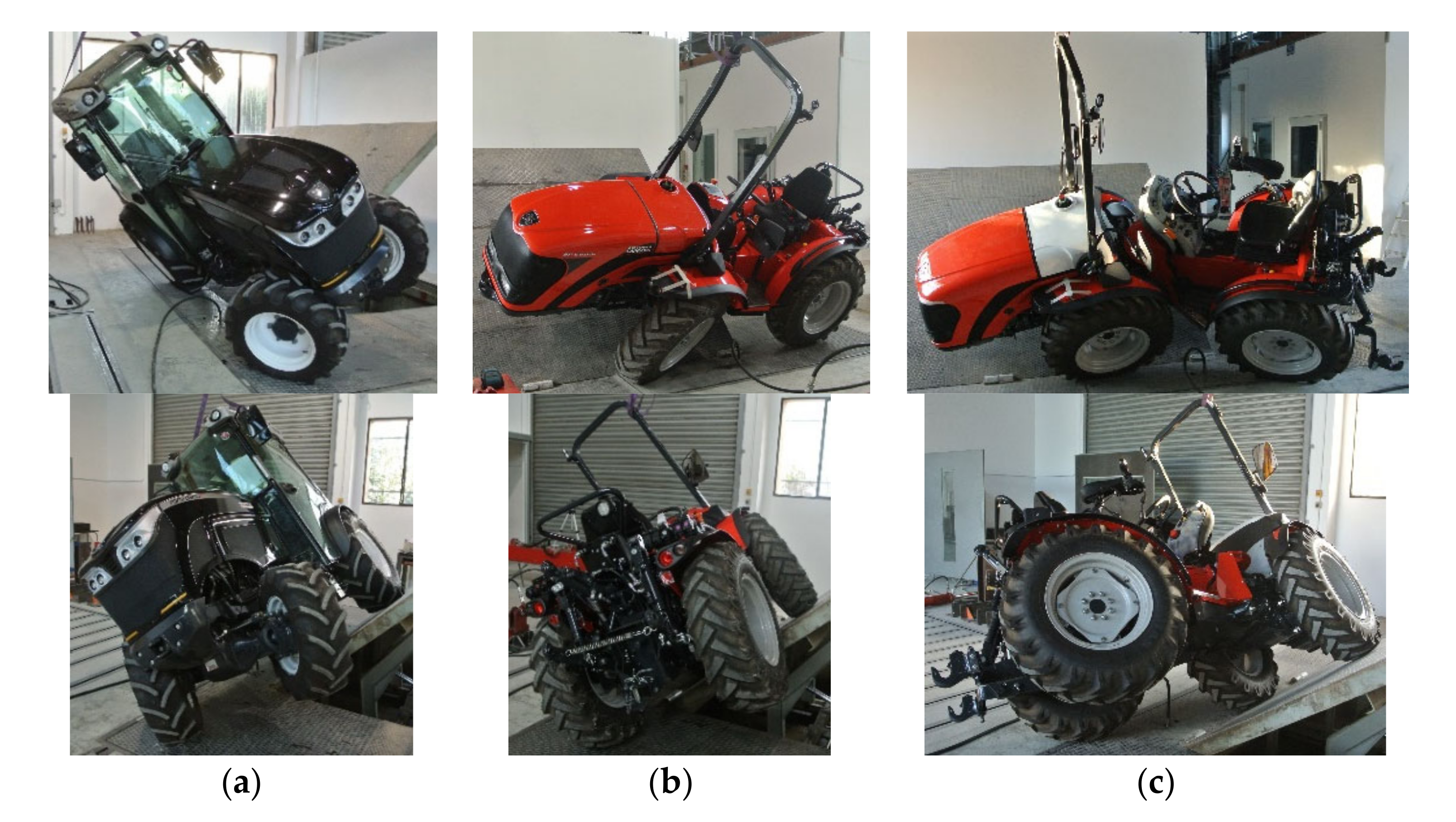
Narrow-track tractors are, nowadays, designed in different configurations that affect the stability performance of the machine [17]. In order to develop the kinematic model, the tipping behaviour of the narrow-track articulated tractor with respect to a fixed chassis tractor was analyzed. The evaluation was carried out by means of an inclined platform to tilt the tractor axle bearing more than 50% of the tractor’s weight [22]. The tractor with a fixed chassis is typically a front steering wheel tractor designed with the pivot point located in the mid-point of the front axle and with more than 50% of the tractor’s weight on the rear axle (Figure 1a). The pivot point is a mechanical tool for the tractor to overcome the ground unevenness. The compact narrow-track tractor is made of two separate bodies joined and the pivot point is close to the geometric center of the tractor. A cantilever engine in the forward position is mounted affecting the tractor Center of Gravity (CoG) and the mass repartition. More than 50% of the tractor weight is loaded on the front axle. The compact tractor can be designed as a steering wheel tractor with only one degree of freedom permitted, the longitudinal rotation (roll angle—ϑ) (Figure 1b). Otherwise, an additional configuration in the design of the compact tractor is represented by the articulated tractor with two degrees of freedom allowed, longitudinal and vertical rotations (roll angle—ϑ and yaw angle—μ) (Figure 1c).
2.2. Kinematic Model for Lateral Stability Test
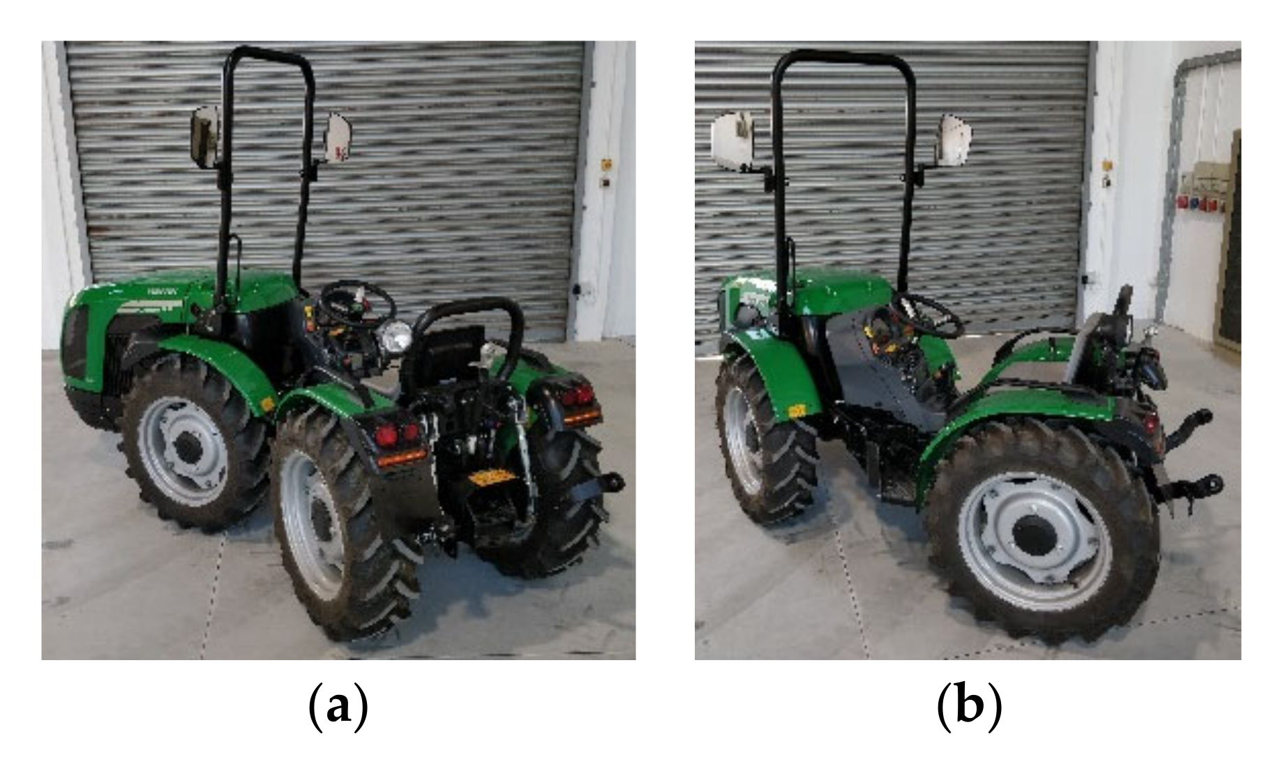
In developing the kinematic model to simulate the behavior of articulated tractor, the design of the tractor was simplified considering a rear body composed of the rear axle and the driver seat, joined to a front body, made of the front axle and the engine. The tractor rear body was allowed to assume an angle of inclination and a position different with respect to the front body because of the pivot point joining the two bodies. This articulation mechanism in the normal operation of the tractor affects its configuration during the steering action, the rear and front parts can mutually rotate to change the tractor path (Figure 2).
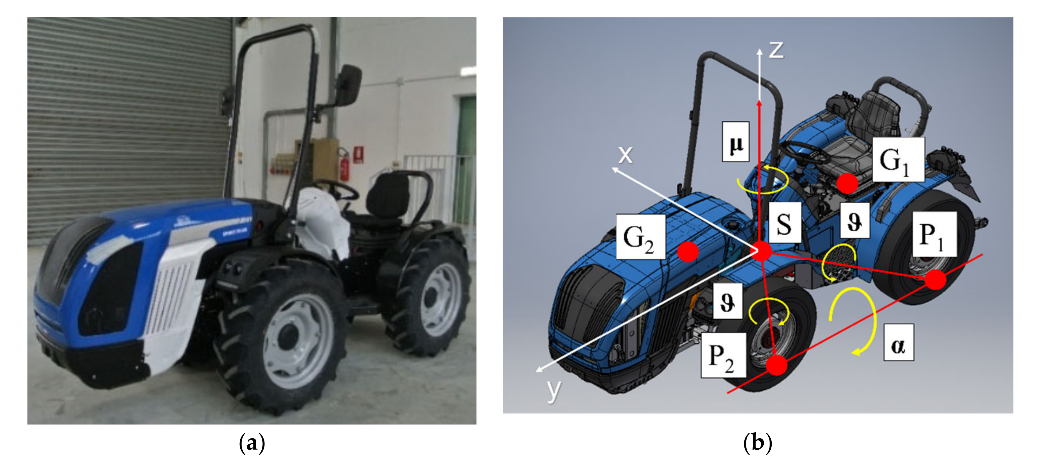
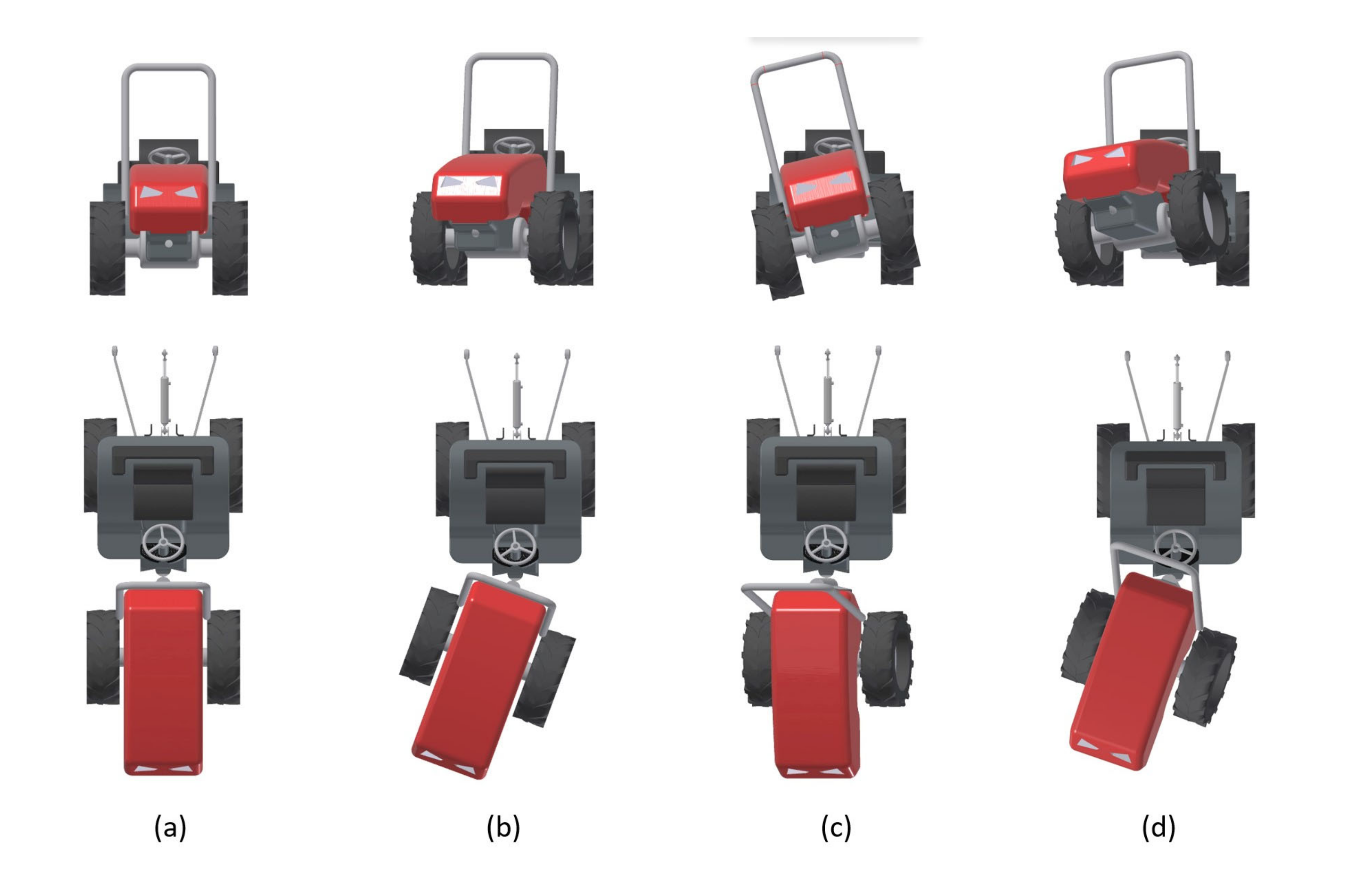
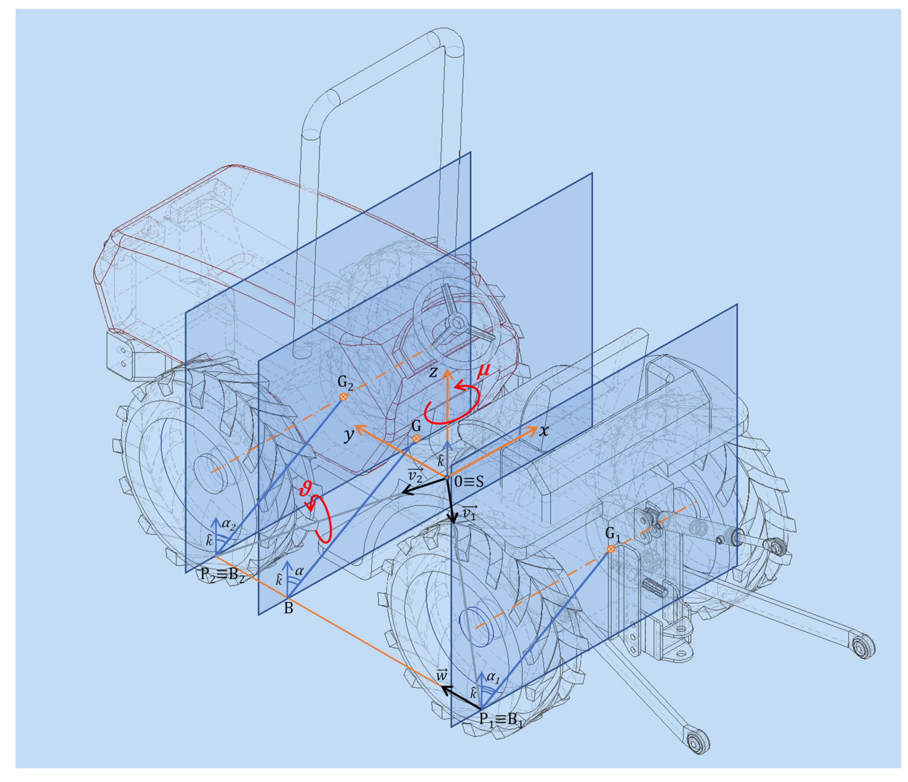
Assumptions made to derive the kinematic model of the tractor were: tractor composed of two rigid bodies centrally joined to permit their mutual rotation; the full tractor CoG divided into two distinct portions that are the rear and front tractor body CoG; tractor median longitudinal plane, defined with respect to the two bodies in the straight configuration, symmetrical and parallel to the y–z plane (Figure 3a and Figure 4a); steering action with respect to the rear body of the tractor; ground surface nondeformable and slip effect of the tractor on the ground ignored. The axis reference system was centred on the joint of the tractor defining the pivot point of the model (S). Five characteristics points were identified to describe the virtual tractor (Figure 3b). The approach in modelling the compact articulated tractor was to represent the complex geometry of the vehicle (Figure 3a) through the decomposition of the tractor into two bodies, front and rear, connected with a joint allowing the rotation on the vertical axis of the tractor (yaw angle—μ, Figure 3b and Figure 4b), on the longitudinal axis (roll angle—ϑ, Figure 3b and Figure 4c) and their mutual rotation (Figure 4d)
where and are the contact points of the rear and front tires on the ground, and specify the position of the CoG of the rear and front bodies of the tractor and is the pivot point of the tractor.
When the tractor tips sideways, the first rotation take place about an axis connecting the central pivot point to the contact point of the tire remaining on the ground during the initial tipping motion. Eventually, the tipping body of the tractor strikes a stop on the steady tractor body with further tipping of the whole tractor taking place about an axis connecting the contact points of the front and rear tires on the ground. The lateral stability angle (α) was defined as the angle the full tractor body CoG must assume from the horizontal position on the ground (with the four tractor tires touching the ground) till the inclined position, corresponding to the unstable equilibrium of the tractor on the two tires is in contact with the ground. The tractor axis of rotation to evaluate the lateral stability angle varies because it is affected by the position of the front and rear wheels in contact with the ground plane; these will assume different positions because of the mutual rotation of the two tractor bodies, defining the boundary condition the CoG must respect to maintain the stability of the tractor. It is clear, even before analyzing the model results, that the lateral stability angle is linked to the tractor configuration. To represent the complex tractor scenario, the first step in modeling was to define a selected configuration based on geometry, masses and mutual position of the two tractor bodies, to define the roll and yaw angle values. In the second step, the corresponding angle of stability was evaluated. Final step was to identify the worst tractor scenario and to calculate the lateral tractor stability limit angle.
Study development:
- (a)
- Modelling the vertical pivot point (yaw angle)
- (b)
- Modelling the horizontal pivot point (roll angle)
- (c)
- Modelling the lateral tractor stability
2.2.1. Modelling the Vertical Pivot Point (Yaw Angle)
A fixed chassis tractor, typically, is designed with front wheels mounted on the steering axle, even if, over the years, the modern tractors have become more and more in the type of four-wheel drive (4WD), where the front axle is, at the same time, a drive and a steering axle. In the fixed chassis tractor design, the yaw angle is equal to zero because the rotation of the front wheels is considered negligible. Taking into consideration the articulated chassis tractor, where the steering action is performed by the rotation of a body with respect to the other body, the effect of this rotation was considered to affect only the points relating to the rear body. The rotation allowed for the joint defines the yaw angle and affects the two points in Equations (1) and (3). Rotation can be clockwise or anti-clockwise, consistent with a right or a left steering action. Having a maximum value of the yaw angle, a parameter defined at the tractor design stage, tractor bodies can assume positions in between the minimum to the maximum articulation values, with zero value when the two bodies are in the straight configuration, which is a configuration equivalent to a fixed chassis tractor.
The angular orientation of the tractor is related to the rotations about the axes. To model the vertical pivot point, the angular rotation is about the z axis and the following rotation matrix is introducing µ as yaw angle
The new contact point of the rear tire on the ground and the new CoG of the rear body of the tractor are represented by the vector equations, respectively and
2.2.2. Modelling the Horizontal Pivot Point (Roll Angle)
The joint connection between the front and the rear body of the tractor allows overcoming of the ground unevenness conditions. In the fixed chassis tractor, the joint is designed in the central position of the front axle and its effect on the stability is reduced. In compact articulated chassis tractors, the joint is located in the central part of the tractor chassis causing the mutual rotation of the two tractor bodies when tractor needs to overcome obstacles or ditches. The range of rotation of the two tractor bodies is defined at the design stage, but this parameter greatly affects the tractor behavior in terms of stability performance. In critical stability conditions, when the tractor reaches the unstable equilibrium, being the different CoGs of the front and rear tractor bodies, there will be one of the two parts that will represent the worst configuration for the stability effect. A loss of adhesion of a wheel on the ground will be observed and the linked body will rotate at an angle equal to the joint angle, defining a new condition for the tractor. The CoG of the rotated body will be affected. Actually, this rotation is not purely longitudinal about a principal axis, but the CoG will rotate about the axis defined by the straight line passing through the contact point of the tire on the ground and the pivot point, for an angle equal to the maximum joint angle. In order to avoid a misunderstanding, this angle has been named roll angle to differentiate it with respect to the yaw angle. In the model, because of the geometry and mass repartition of the compact tractor, the roll angle behavior was ascribed both to the front and to the rear tractor bodies. Since the initial tipping motion does not take place around either the x, y, or z axes, it is convenient to define the skew coordinate axis about which the tractor is assumed to tip. Introducing ϑ as roll angle and assuming as the unit vector in the direction of the first tipping axis (i = 1 for the rear body and i = 2 for the front body), according to the method of Smith et al. [20], a rotation matrix can be defined.
Nevertheless, to improve the understanding, the rotation matrix was related only to the front body of the tractor.
Considering the change in the rotation matrix to reproduce a clockwise rotation, the new CoG of the front body of the tractor was defined as
2.2.3. Modelling of Lateral Tractor Stability
Based on the CoG of the two tractor bodies, affected by the rotation angles and the masses of the two bodies, the CoG of the whole tractor in the defined scenario was computable. The stability angle of the tractor was calculated by considering the unstable equilibrium when the tractor CoG position falls outside the basis connecting the contact points of the tires on the ground. A determination of the CoG on the whole tractor is essential in any prediction of vehicle behavior; it is through the CoG position that the gravity force, if outside the axis connecting the contact points of the front and rear tires on the ground, causes the instability of the tractor. Taking into consideration the distribution of the masses of the tractor, the roll and yaw angles consequently affected the CoG position and the lateral stability angle. Letting be the weight of the rear tractor body, the weight of the front tractor body and the weight of the whole tractor , the new CoG of the tractor at the instant the tractor begins to tip is located at the point with coordinates
Letting be a unit vector in the direction of the second tipping axis connecting the contact points of the front and rear tires on the ground , the intersection point between the second tipping axis and a plane passing through the CoG of the whole tractor perpendicular to the second tipping axis (Figure 5), was defined
The tractor stability angle was calculated according to the scalar product propriety between the vector and the vector with the same intensity but vertical direction
The stability angle related to the rear body (i = 1) or to the front body (i = 2) was calculated according to the previous equations considering the intersection point between the first tipping axis and a plane passing through the CoG of the rear or the front bodies perpendicular to the second tipping axis.
where and are the stability angles of the rear and front bodies, respectively.
The lateral stability angle of the whole tractor, assuming a defined Yaw angle, while the Roll angle is variable in between ϑ = 0 and ϑ = ϑmax, was calculated according to the following sequence
The first step was to consider ϑ = 0, Equation (24), in order to calculate the stability angles of the front, the rear and the whole tractor bodies. If , the whole tractor body reaches the unstable condition before the front and the rear bodies, Equation (25), and the limit stability angle is defined by . Otherwise, , the front or the rear body reaches the unstable condition before the whole tractor body, Equation (25). In this situation, representing the stability angle of the whole tractor body rotated to an angle equal to , has to be considered, Equation (26). If , the whole tractor has already reached the unstable condition because of its lower stability angle, and the limit stability angle is defined by considering , Equation (28). Otherwise, , the whole tractor reaches the unstable condition after the rotation, and the limit stability angle is defined by , Equation (29).
The values of the input parameters, representing the average values of the current narrow-track tractors available on the market, are derived from Franceschetti et al. [6]. Table 1 lists the geometrical input parameters of the tractor configuration considered in the simulation (Figure 5). The CoG tractor positions of the rear and front bodies were located, respectively, on the rear and the front axles. The rear and front tractor body weights were based on the axles mass repartition of the whole tractor. The CoG heights were determined using an oscillating platform [23]. The measurement instruments to test the tractor are provided in Table 2.
3. Results
The model was used to examine the behavior of the tractor to variable inputs of the yaw angle to mimic the steering action behavior. In addition, the roll angle allowed for analyzing of the mutual rotation effect between the rear and front bodies. By combining the effect of the roll and yaw angles, all of the tractor configurations due to the articulated joint were reproduced; consequently, the critical value of the stability angle was determined and the worst condition for the stability of the whole tractor was established. The results shown refer to two tractor configurations: straight configuration and articulated configuration.
3.1. Straight Configuration
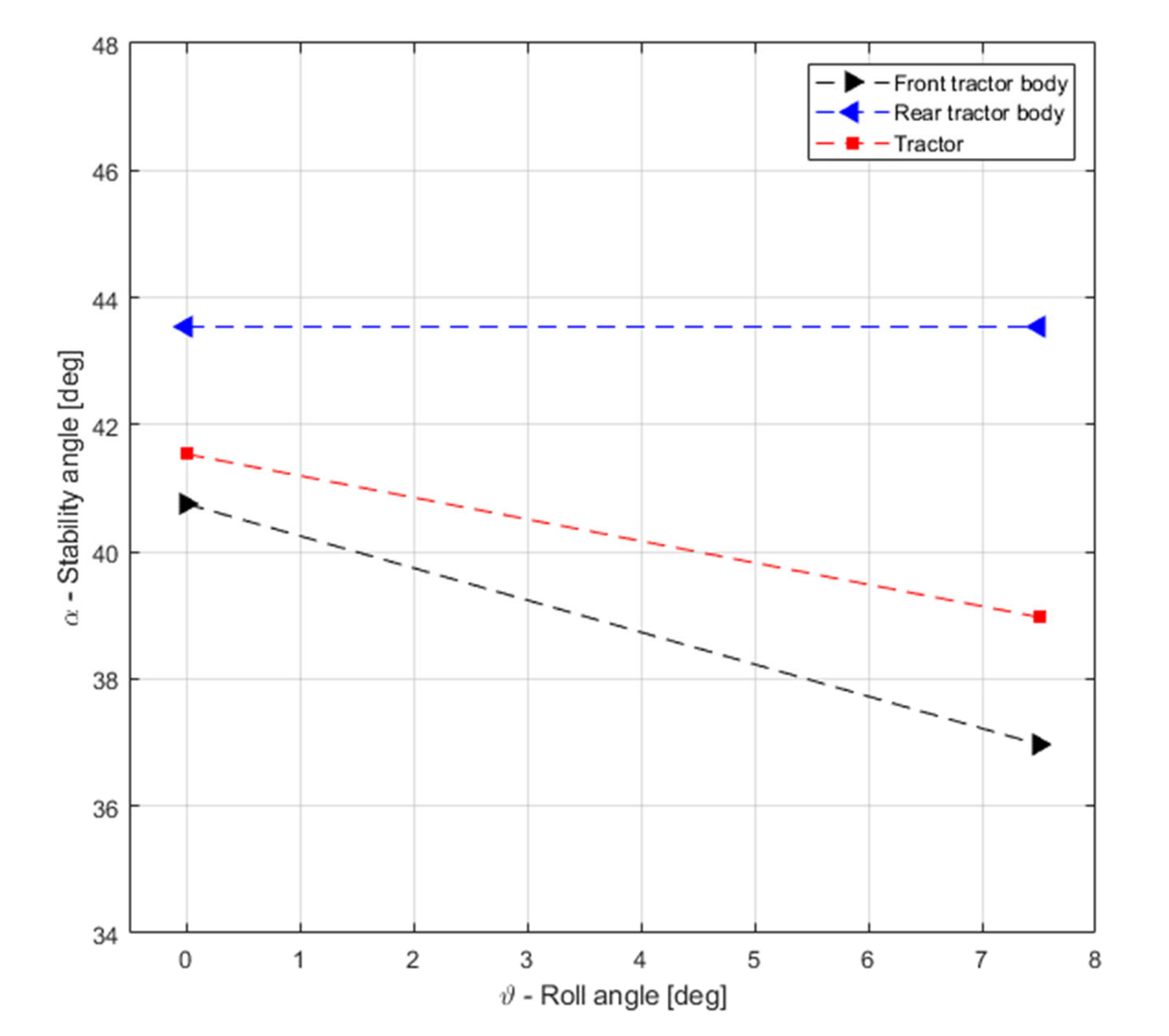
An articulated tractor in the straight configuration is comparable to a steering wheel tractor (Figure 1b). The model simulates the overturning event by increasing progressively the slope of the ground until a part of the tractor loses stability. Although the simplest case is a fixed chassis tractor without roll angle (α = 41.5°), the model is able to perform the analysis considering the roll angle (ϑ ≠ 0°) without the yaw angle contribution (μ = 0°). In this study, the front body turned out first (α2 = 40.8°) with respect to the whole tractor; therefore, the overturning starts with the rotation of the front body (Figure 6, ϑ = 0°). The front body rotates about the first tipping axis ( vector) depending on the design roll angle (7.5°, Table 1), basically, until the rotating body rests on the stationary body (rear body). In Figure 6, the behavior of the front tractor body, rear body and the whole tractor, at different roll angle values, are shown. The loss of stability of the front body with respect to the stability of the rear body leads to the change in the CoG of the tractor and this affects the stability angle. In fact, when the front body loses stability, it causes the tractor to become unstable, since the original stability value of 41.5° changes to 39.0°. This means that when the front body loses stability at 40.8°, the whole tractor begins to overturn (ϑ = 7.5°; α = 39.0°). It is to be noted that it is not necessarily the loss of stability of the front body that causes the loss of stability of the whole tractor. In the first step, there is only a reciprocal rotation between the two bodies, which can eventually cause the beginning of the tractor overturning event. The effect of the velocity of the front body due to the loss of stability could cause a different behavior with respect to the simulated one because the dynamic effect is not considered here. In Figure 6, it has to be underlined that the lateral stability trend, for the front body and the whole tractor, is linear decreasing as the roll angle increases, and the tractor reaches the condition of instability at α = 40.8° when the front body loses stability. The rear body remains in the condition of a stationary body and, therefore, the stability value is unchanged. If the tractor, for some reason, i.e., external force, has the front body already in a rotated condition, it reaches the condition of instability (α = 39.0°) earlier. Calculating the limit of the angle at the tractor design stage, engineers can manage the roll angle with respect to the needs of the end user.
3.2. Articulated Configuration
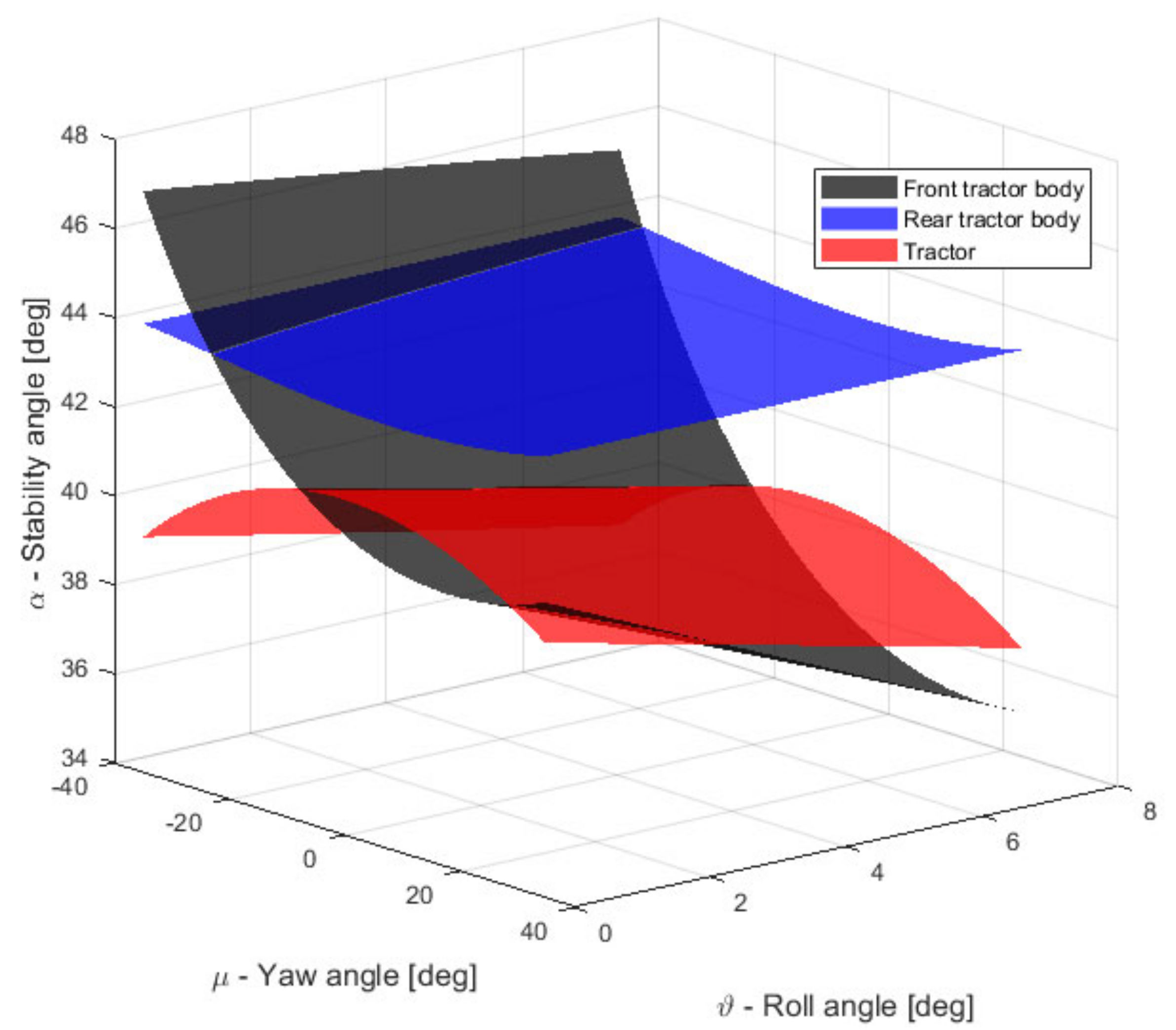
If the tractor steers the front and the rear tractor bodies by means of the articulation joint, it is necessary to analyze the lateral stability depending on the degree of tractor articulation (Figure 2—μ ≠ 0°). The lateral stability of the tractor was assessed by tilting the tractor until it induced it to tip over. The scenario will vary according to the configuration of the tractor, and it will depend on the rotation of the articulation between the front and the rear tractor bodies. Considering the lower value of the yaw angle, equal to −35 degrees (Table 1), the tractor will be fully steered or articulated to the left (Figure 2a), while for the yaw angle equal to +35° the tractor will be fully articulated to the right (Figure 2b). The roll angle (ϑ ≠ 0°) acts through the rotation of one body on the other. The stability angles of the separate bodies and that of the whole tractor are shown in Figure 7. The curves represent the trend of the stability angle as a function of the yaw angle μ and the roll angle ϑ. Three surfaces are shown that represent the variation in the stability angle for the front body, the rear body and the whole tractor. The most significant variation is related to the front body, for which the stability angle varies from 35.7° to 47.0°.
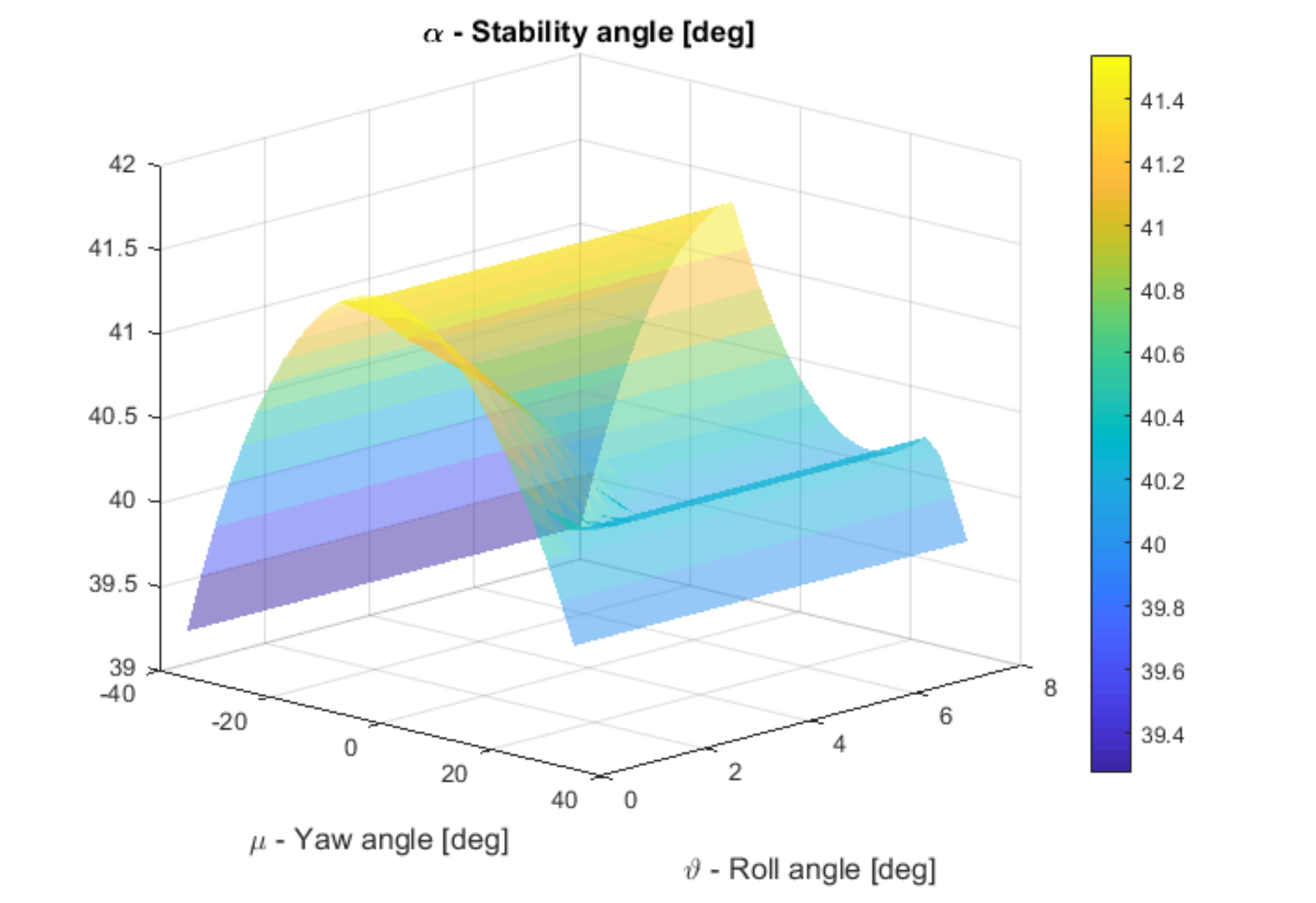
Although all of the tractor configurations are shown in the Figure 7, it is not always in the normal operation that the tractor overturning events will take place. Some tractor configurations, in which the front or rear body rotates to an angle equal to the roll angle, will not occur. In fact, rotation about the second tipping axis may not happen if the overturn occurs at the rotation about the first tipping axis. Considering the logical sequence from Equation (24) to Equation (29), the foreseeable configurations are shown in Figure 8, where the limit stability angle varies from 39.3° to 41.5°.
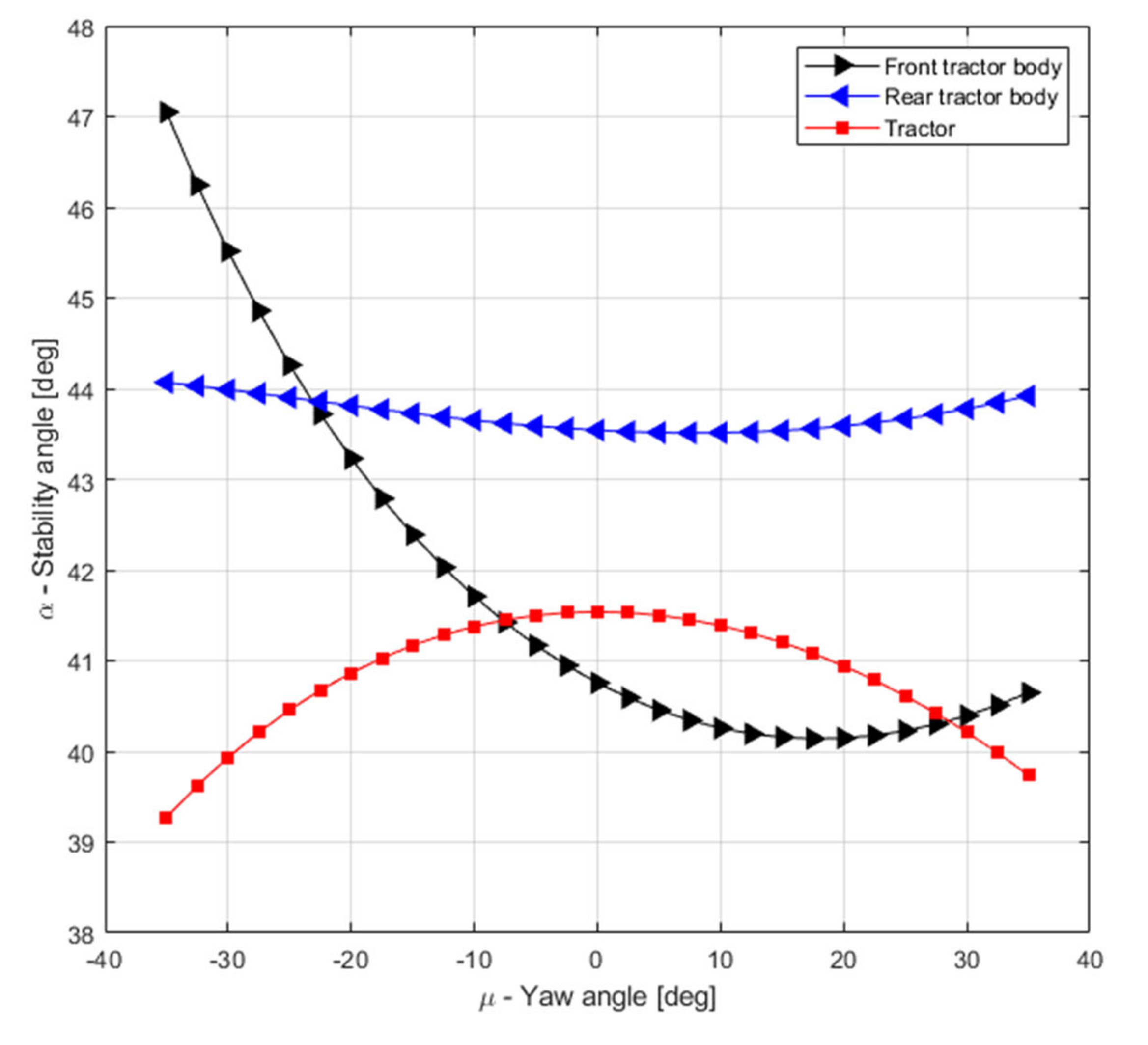
To better understand the body of the tractor that loses stability first, the results have been simplified by selecting the roll angle equal to zero (Figure 9). The first observation is that the results in Figure 6 and Figure 9 are comparable when the roll and yaw angles are equal to zero. The rear tractor body is slightly affected by the Yaw angle rotation and will never start the overturning event, while the front tractor body and the whole tractor lines are intersecting, and this suggests a turnover between the trigger of the overturning cause. Depending on the tractor configuration, there are situations where the whole tractor will lose stability first and other cases where the front body will start the rollover. The pivot point of the tractor (S) is lower with respect to the CoG heights of the two tractor bodies and, being closer to the front body CoG (G2), the stability angle of the tractor front body is more affected than that of the rear body. Consequently, the behaviour shown in Figure 9 refers to an asymmetrical and non-linear trend. In detail, in between −35° and −22° of the yaw angle, the front body stability angle is high, showing a strong stable condition. Opposite to the behaviour of the whole tractor stability. This behaviour is related to the tractor articulation affecting the contact point of the tires on the ground and, consequently, the first and the second tipping axes. The yaw rotation (negative and positive) moves the CoG of the whole tractor close to the second tipping axis, worsening the tractor stability angle. In between −7.5° and 27.5° of the yaw angle, the front tractor body causes the overturning event.
4. Discussion
The lateral stability angle of an articulated narrow-track tractor was calculated, developing a kinematic model. The results were split into two tractor configurations: straight configuration and articulated configuration. Stability angles were calculated for the front body, rear body and whole tractor.
In detail, the lateral stability angle for the tractor in the straight configuration was 40.8° at the condition with 0° roll angle (front body unstable condition), and 39.0° at the condition with 7.5° roll angle (whole tractor unstable condition). When forcing the tractor to behave as a fixed chassis tractor (no roll angle), the stability angle was 41.5°.
In the case of an articulated configuration, the angle of stability is not unique and depends on the yaw angle. The lower value of the stability angle is 39.3°, measured at a −35° yaw angle. These values fulfil the required angle value of the tractors equipped with a front ROPS because the OECD angle must be at least 38° at the moment when the tractor is resting in a state of unstable equilibrium [22]. However, difficulties are related to the definition of the lateral stability limit angle of the articulated tractor due to the roll and yaw angle combined effects. The lateral stability angles are theoretically calculated considering the rotation of the tractor with respect to a line passing through the contact points of the tires on the ground. In detail, the contact point was considered to be located in the middle of the tire width. Nevertheless, the tire deformation behaviour during an actual rollover can significantly affect the contact points of the tire on the ground.
5. Conclusions
This study combines known facts and engineering principles related to articulated narrow-track tractor design to predict, with a kinematic model, the tractor behavior on sloped ground. The model was set up for the steady-state behavior, and it predicted the orientation as well as the stability of the vehicle on idealized slopes.
The lateral stability angle was linear, decreasing as the roll angle increased. Otherwise, the lateral stability angle had a non-linear trend when related to the yaw angle.
The lowest stability angle was 39.3°, obtained at the extreme value of the yaw angle, −35°, equivalent to the maximum steering action of the tractor. The results presented do not consider all the phenomena of friction, air resistance, internal moving liquids and dynamic behaviour that could occur during a real overturn. Various parameter values were used in a computer analysis to study the effects of tractor geometry, including the articulation possibilities of the tractor. The dynamic effect of the central pivot point during the rotation of one body of the tractor with respect to the second one, if not properly damped by suitable viscoelastic components, might negatively affect the stability angle, leading to an early rollover. Nevertheless, the effects of dynamic parameters such as vehicle acceleration on overturning were assumed to be negligible and not affecting the tractor stability analysis.
The kinematic model allows researchers to analyze tractors with geometry and CoG positions known. This means that the model could be a useful tool for the manufacturer in the design process to optimize tractor operation on a sloping ground, increasing the safety for the driver and, consequently, the comfort and suitability of the tractor, properly balancing the tractor bodies joined in the whole tractor. The results highlighted critical situations for improvements in design as well as horizons for future study.
Author Contributions
Conceptualization, B.F., V.R. and E.C.; methodology, B.F. and V.R.; software, B.F.; investigation, B.F.; data curation, B.F.; writing—original draft preparation, B.F.; writing—review and editing, B.F., V.R. and E.C.; visualization, B.F. and E.C.; supervision, V.R. and E.C. All authors have read and agreed to the published version of the manuscript.
Funding
This research received no external funding.
Institutional Review Board Statement
Not applicable.
Informed Consent Statement
Not applicable.
Data Availability Statement
Not applicable.
Acknowledgments
The Authors appreciated the support and help of the Staff of the Laboratorio di Meccanica Agraria, OECD Testing station of the DISTAL, University of Bologna, Italy. The valuable contribution of Antonio Carraro S.p.A. and BCS S.p.A. is acknowledged; special thanks to Alberto Benetello and Federico Soresina for their support in providing the 3D drawings of the tractors.
Conflicts of Interest
The authors declare no conflict of interest.
References
- Hunter, A.G.M.; Owen, G.M. Tractor Overturning Accidents on Slopes. J. Occup. Accid. 1983, 5, 195–210. [Google Scholar] [CrossRef]
- Rondelli, V.; Martelli, R.; Casazza, C. Tractor Rollover Fatalities, Analyzing Accident Scenario. J. Saf. Res. 2018, 67, 99–106. [Google Scholar] [CrossRef]
- Shu, M.; Ahmad, D.; Akande, F.B. A Review of Farm Tractor Overturning Accidents and Safety. Pertanika J. Sci. Technol. 2010, 18, 377–385. [Google Scholar]
- Kim, K.U.; Rehkugler, G.E. A Review of Tractor Dynamics and Stability. Trans. ASAE 1987, 30, 615–623. [Google Scholar] [CrossRef]
- Guzzomi, A.; Rondelli, V. Narrow-Track Wheeled Agricultural Tractor Parameter Variation. J. Agric. Saf. Health 2013, 19, 237–260. [Google Scholar] [CrossRef] [PubMed]
- Franceschetti, B.; Rondelli, V.; Ciuffoli, A. Comparing the Influence of Roll-Over Protective Structure Type on Tractor Lateral Stability. Saf. Sci. 2019, 115, 42–50. [Google Scholar] [CrossRef]
- Guzzomi, A.L. A Revised Kineto-Static Model for Phase I Tractor Rollover. Biosyst. Eng. 2012, 113, 65–75. [Google Scholar] [CrossRef]
- Spencer, H.B. Stability and Control of Two-Wheel Drive Tractors and Machinery on Sloping Ground. J. Agric. Eng. Res. 1978, 23, 169–188. [Google Scholar] [CrossRef]
- Grecenko, A. Operation on Steep Slopes: State of The Art Report. In Proceedings of the Eighth International Conference of the International Society for Terrain-Vehicle Systems, Cambridge, UK, 6–10 August 1984; Volume 21, pp. 181–194. [Google Scholar]
- Yisa, M.G.; Terao, H.; Noguchi, N.; Kubota, M. Stability Criteria for Tractor-Implement Operation on Slopes. J. Terramech. 1998, 35, 1–19. [Google Scholar] [CrossRef]
- Pershing, R.L.; Yoerger, R.R. Simulation of Tractors for Transient Response. Trans. ASAE 1969, 12, 715–719. [Google Scholar] [CrossRef]
- Franceschetti, B.; Lenain, R.; Rondelli, V. Comparison between a Rollover Tractor Dynamic Model and Actual Lateral Tests. Biosyst. Eng. 2014, 127, 79–91. [Google Scholar] [CrossRef]
- Guzzomi, A.; Rondelli, V.; Guarnieri, A.; Molari, G.; Molari, P.G. Available Energy during the Rollover of Narrow-Track Wheeled Agricultural Tractors. Biosyst. Eng. 2009, 104, 318–323. [Google Scholar] [CrossRef]
- Franceschetti, B.; Capacci, E.; Rondelli, V. Effects of Rubber Tracks on Narrow-Track Tractors on the Non-Continuous Rolling Prediction Model. J. Agric. Saf. Health 2016, 22, 262–273. [Google Scholar] [CrossRef] [Green Version]
- Capacci, E.; Franceschetti, B.; Guzzomi, A.; Rondelli, V. Energy Absorption in Actual Tractor Rollovers with Different Tire Configurations. Int. J. Environ. Res. Public Health 2021, 18, 6517. [Google Scholar] [CrossRef] [PubMed]
- Li, Z.; Mitsuoka, M.; Inoue, E.; Okayasu, T.; Hirai, Y.; Zhu, Z. Parameter Sensitivity for Tractor Lateral Stability against Phase I Overturn on Random Road Surfaces. Biosyst. Eng. 2016, 150, 10–23. [Google Scholar] [CrossRef]
- Guzzomi, A.L.; Rondelli, V.; Capacci, E. Operator Protection in Rollover Events of Articulated Narrow Track Tractors. Biosyst. Eng. 2019, 185, 103–115. [Google Scholar] [CrossRef]
- Liu, J.; Ayers, P.D. Off-Road Vehicle Rollover and Field Testing of Stability Index. J. Agric. Saf. Health 1999, 5, 59–71. [Google Scholar] [CrossRef]
- Gibson, H.G.; Elliot, K.C.; Persson, S.P.E. Side Slope Stability of Articulated—Frame Logging Tractors. J. Terramech. 1971, 8, 65–79. [Google Scholar] [CrossRef]
- Mazzetto, F.; Bietresato, M.; Gasparetto, A.; Vidoni, R. Simulated Stability Tests of a Small Articulated Tractor Designed for Extreme-Sloped Vineyards. J. Agric. Eng. 2013, 44, 663–668. [Google Scholar] [CrossRef]
- Smith, D.W.; Perumpral, J.V.; Liljedahl, J.B. The Kinematics of Tractor Sideways Overturning. Trans. Am. Soc. Agric. Eng. 1974, 17, 1–3. [Google Scholar] [CrossRef]
- OECD. Code 6: OECD Standard Code for the Official Testing of Front Mounted Roll-Over Protective Structures on Narrow-Track Wheeled Agricultural and Forestry Tractors, Organisation for the Economic Co-Operation and Development. Available online: www.oecd.org/agriculture/tractor/codes (accessed on 1 June 2021).
- Casini-Ropa, G. Equipment and Methods for the Measurement of the Height from the Ground of the Centre of Gravity on Agricultural Machinery [Attrezzatura e Metodo per Il Rilievo Da Terra Dell’altezza Del Baricentro Delle Machine Agricole]. Riv. Ing. Agrar. 1976, 2, 81–85. [Google Scholar]
Figure 1.
Preliminary analysis of the narrow-track tractors: (a) steering wheel tractor with a fixed chassis; (b) compact steering wheel tractor; (c) compact articulated tractor.
Figure 1.
Preliminary analysis of the narrow-track tractors: (a) steering wheel tractor with a fixed chassis; (b) compact steering wheel tractor; (c) compact articulated tractor.

Figure 2.
Articulated tractor: (a) articulation to the left; (b) articulation to the right.

Figure 3.
Compact articulated tractor: (a) Actual tractor in the straight configuration; (b) Graphical representation of the tractor parameters assumed in modelling: P1, P2, G1, G2 and S are the five characteristics points defined in the modeling approach related to the geometrical tractor configuration, μ is the yaw angle, ϑ is the roll angle and, α is the tractor stability angle.

Figure 4.
The configurations of the compact articulated chassis tractor: (a) Straight; (b) Yaw angle; (c) Roll angle; (d) Yaw and Roll angles.
Figure 4.
The configurations of the compact articulated chassis tractor: (a) Straight; (b) Yaw angle; (c) Roll angle; (d) Yaw and Roll angles.

Figure 5.
Graphical representation of the input tractor parameters considered in the simulation.

Figure 6.
Tractor in the straight configuration: tractor stability angles vs. Roll angle. Front tractor body (black line), rear tractor body (blue line) and whole tractor (red line).
Figure 6.
Tractor in the straight configuration: tractor stability angles vs. Roll angle. Front tractor body (black line), rear tractor body (blue line) and whole tractor (red line).

Figure 7.
The stability angles of the separate bodies and the whole tractor vs. Yaw angle and Roll angle. Front body (black surface), the rear body (blue surface) and the whole tractor (red surface).
Figure 7.
The stability angles of the separate bodies and the whole tractor vs. Yaw angle and Roll angle. Front body (black surface), the rear body (blue surface) and the whole tractor (red surface).

Figure 8.
The foreseeable stability angles of the whole tractor vs. Yaw angle and Roll angle.

Figure 9.
Tractor in the articulated configuration: tractor stability angles vs. Yaw angle. Front tractor body (black line), rear tractor body (blue line) and whole tractor (red line).
Figure 9.
Tractor in the articulated configuration: tractor stability angles vs. Yaw angle. Front tractor body (black line), rear tractor body (blue line) and whole tractor (red line).


Table 1.
Input tractor parameters.
| Identification | Geometric Parameter | Unit | Description |
|---|---|---|---|
| (−555; −915; −540) | mm | Rear tire contact point | |
| (−555; 425; −540) | mm | Front tire contact point | |
| (0; −915; 44) | mm | CoG Rear tractor body | |
| (0; 425; 104) | mm | CoG Front tractor body | |
| (0; 0; 0) | mm | Pivot point | |
| W1 | 450 | kg | Rear tractor body weight |
| W2 | 1090 | kg | Front tractor body weight |
| ϑ | (0 ÷ 7.5) | degrees | Roll angle |
| μ | (−35 ÷ 35) | degrees | Yaw angle |
Table 2.
Measurement instruments of the tractor preliminary test.
| Instrument | Purpose | Specifications |
|---|---|---|
| Static scale | Mass | Range 40–6000 kg Increment 2 kg |
| Digital laser Rangefinder | Linear displacement | Range 3000 mm Increment 1 mm |
| Angle | Angle Range 0–360° (4 × 90°) Increment 0.2° | |
| Proximity switch | Timer/Counter | Range 100 ns–10 s Increment 0.1 μs |
Publisher’s Note: MDPI stays neutral with regard to jurisdictional claims in published maps and institutional affiliations. |
© 2021 by the authors. Licensee MDPI, Basel, Switzerland. This article is an open access article distributed under the terms and conditions of the Creative Commons Attribution (CC BY) license (https://creativecommons.org/licenses/by/4.0/).
Share and Cite
MDPI and ACS Style
Franceschetti, B.; Rondelli, V.; Capacci, E. Lateral Stability Performance of Articulated Narrow-Track Tractors. Agronomy 2021, 11, 2512. https://0-doi-org.brum.beds.ac.uk/10.3390/agronomy11122512
AMA Style
Franceschetti B, Rondelli V, Capacci E. Lateral Stability Performance of Articulated Narrow-Track Tractors. Agronomy. 2021; 11(12):2512. https://0-doi-org.brum.beds.ac.uk/10.3390/agronomy11122512
Chicago/Turabian StyleFranceschetti, Bruno, Valda Rondelli, and Enrico Capacci. 2021. "Lateral Stability Performance of Articulated Narrow-Track Tractors" Agronomy 11, no. 12: 2512. https://0-doi-org.brum.beds.ac.uk/10.3390/agronomy11122512
Note that from the first issue of 2016, this journal uses article numbers instead of page numbers. See further details here.