
Microfluidics for 3D Cell and Tissue Cultures: Microfabricative and Ethical Aspects Updates
 ,
,  , , , , , , , and
Abstract
:
1. Introduction
2. Discussion
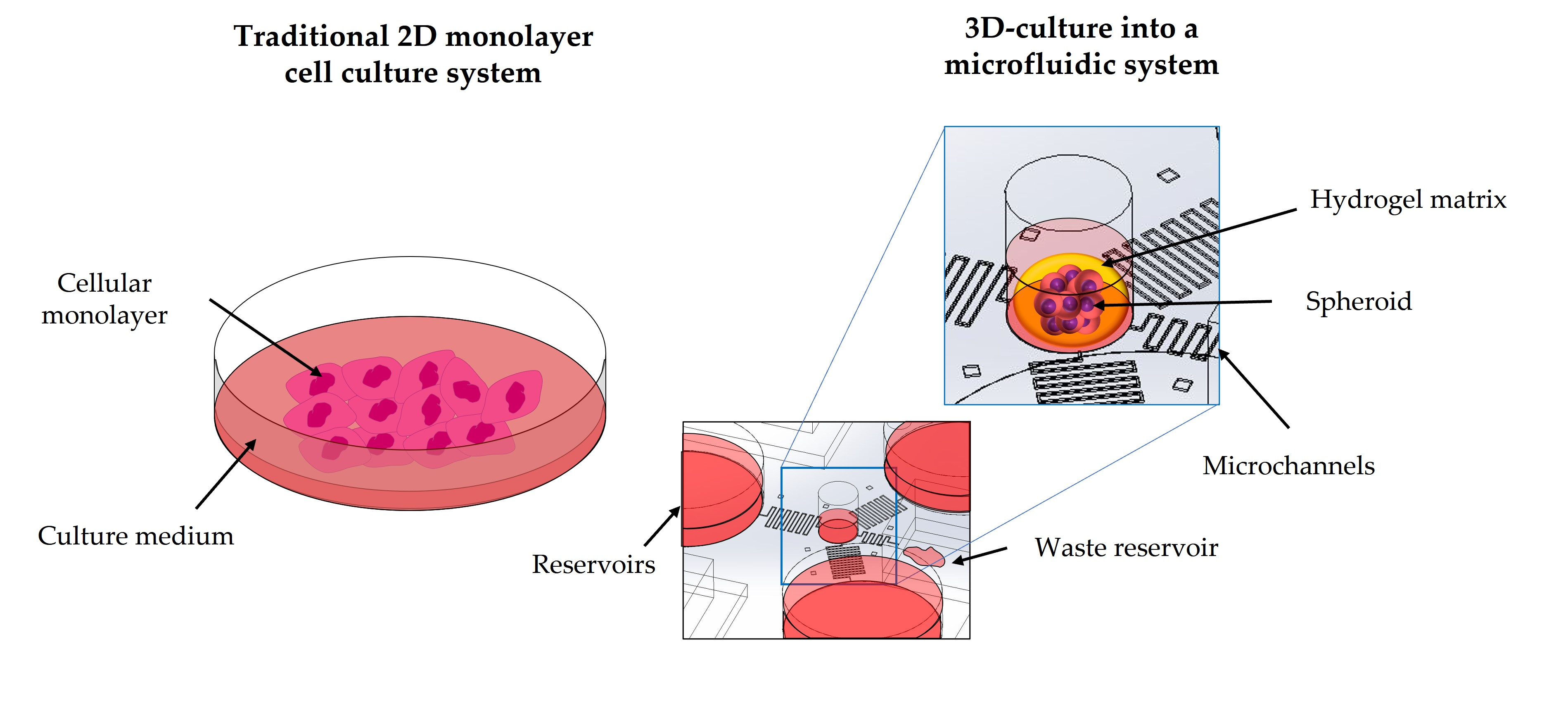
2.1. Physiological Exchange of Substances
2.2. Theory behind the Molecule Transport Mechanisms
- is the concentration gradient of a generic molecule between the external and internal part of the capillary membrane;
- is the permeability coefficient and can be calculated as:
- is the capillary membrane thickness;
- is the partition coefficient and can be calculated as:
- is the number of pores;
- is the capillary surface;
- is the pore radius;
- is the pore density;
- is the membrane diffusion coefficient and can be calculated as:
- is the hindrance coefficient and it depends on the particle and membrane pore dimension and the trajectory of the particle within the pore and can be calculated as:
- is a coefficient that depends on the trajectory of the particle inside the pore;
- is the particle radius (it is an approximation which considers the molecules passing the pore to have a spherical shape);
- is the diffusion coefficient which can be calculated as:
- is the Boltzman constant;
- is the temperature;
- is the blood viscosity;
- is the hydraulic pressure gradient across the capillary membrane;
- is the osmotic pressure gradient across the capillary membrane;
- is the filtration coefficient and can be calculated as:
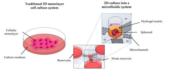
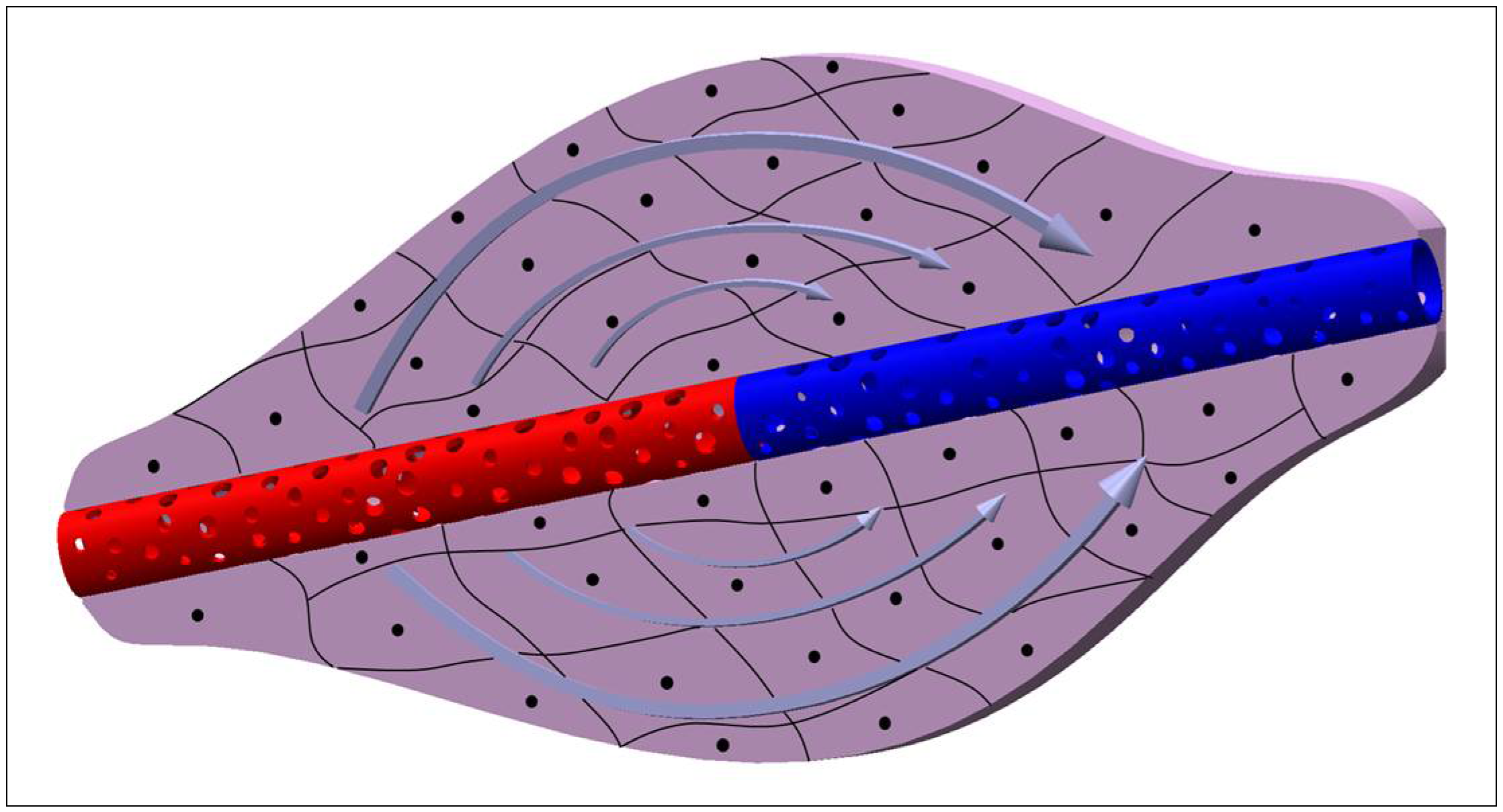
2.3. Cell Microenvironment: Static and 3D Cell Screening
2.4. Microfluidic Cell Screening Devices
3. Conclusions
Author Contributions
Funding
Conflicts of Interest
References
- Jensen, C.; Teng, Y. Is It Time to Start Transitioning From 2D to 3D Cell Culture? Front. Mol. Biosci. 2020, 7, 33. [Google Scholar] [CrossRef] [PubMed] [Green Version]
- Eder, C.; Falkner, E.; Nehrer, S.; Losert, U.M.; Schoeffl, H. Introducing the concept of the 3Rs into tissue engineering research. Altex 2006, 23, 17–23. [Google Scholar] [PubMed]
- Kapałczyńska, M.; Kolenda, T.; Przybyła, W.; Zajączkowska, M.; Teresiak, A.; Filas, V.; Ibbs, M.; Bliźniak, R.; Łuczewski, Ł.; Lamperska, K. 2D and 3D cell cultures-a comparison of different types of cancer cell cultures. Arch. Med. Sci. 2018, 14, 910–919. [Google Scholar] [CrossRef] [PubMed]
- Ravi, M.; Paramesh, V.; Kaviya, S.R.; Anuradha, E.; Solomon, F.D. 3D cell culture systems: Advantages and applications. J. Cell. Physiol. 2015, 230, 16–26. [Google Scholar] [CrossRef]
- Li, X.J.; Valadez, A.V.; Zuo, P.; Nie, Z. Microfluidic 3D cell culture: Potential application for tissue-based bioassays. Bioanalysis 2012, 4, 1509–1525. [Google Scholar] [CrossRef] [Green Version]
- Toh, Y.C.; Lim, T.C.; Tai, D.; Xiao, G.; van Noort, D.; Yu, H. A microfluidic 3D hepatocyte chip for drug toxicity testing. Lab Chip 2009, 9, 2026–2035. [Google Scholar] [CrossRef]
- Carrion, B.; Huang, C.P.; Ghajar, C.M.; Kachgal, S.; Kniazeva, E.; Jeon, N.L.; Putnam, A.J. Recreating the perivascular niche ex vivo using a microfluidic approach. Biotechnol. Bioeng. 2010, 107, 1020–1028. [Google Scholar] [CrossRef] [Green Version]
- Cuchiara, M.P.; Allen, A.C.B.; Chen, T.M.; Miller, J.S.; West, J.L. Multilayer microfluidic PEGDA hydrogels. Biomaterials 2010, 31, 5491–5497. [Google Scholar] [CrossRef]
- Choi, J.; Kim, S.; Jung, J.; Lim, Y.; Kang, K.; Park, S.; Kang, S. Wnt5a-mediating neurogenesis of human adipose tissue-derived stem cells in a 3D microfluidic cell culture system. Biomaterials 2011, 32, 7013–7022. [Google Scholar] [CrossRef]
- Locatelli, L.; Inglebert, M.; Scrimieri, R.; Sinha, P.K.; Zuccotti, G.V.; Milani, P.; Bureau, L.; Misbah, C.; Maier, J.A.M. Human endothelial cells in high glucose: New clues from culture in 3D microfluidic chips. FASEB J. Off. Publ. Fed. Am. Soc. Exp. Biol. 2022, 36, e22137. [Google Scholar] [CrossRef]
- Jachter, S.L.; Simmons, W.P.; Estill, C.; Xu, J.; Bishop, C.V. Matrix-free three-dimensional culture of bovine secondary follicles to antral stage: Impact of media formulation and epidermal growth factor (EGF). Theriogenology 2022, 181, 89–94. [Google Scholar] [CrossRef]
- Langhans, S.A. Three-Dimensional in Vitro Cell Culture Models in Drug Discovery and Drug Repositioning. Front. Pharmacol. 2018, 9. [Google Scholar] [CrossRef]
- Wang, H.; Brown, P.C.; Chow, E.C.Y.; Ewart, L.; Ferguson, S.S.; Fitzpatrick, S.; Freedman, B.S.; Guo, G.L.; Hedrich, W.; Heyward, S.; et al. 3D cell culture models: Drug pharmacokinetics, safety assessment, and regulatory consideration. Clin. Transl. Sci. 2021, 14, 1659–1680. [Google Scholar] [CrossRef]
- Olgasi, C.; Cucci, A.; Follenzi, A. iPSC-Derived Liver Organoids: A Journey from Drug Screening, to Disease Modeling, Arriving to Regenerative Medicine. Int. J. Mol. Sci. 2020, 21, 6215. [Google Scholar] [CrossRef]
- Belfiore, L.; Aghaei, B.; Law, A.M.K.; Dobrowolski, J.C.; Raftery, L.J.; Tjandra, A.D.; Yee, C.; Piloni, A.; Volkerling, A.; Ferris, C.J.; et al. Generation and analysis of 3D cell culture models for drug discovery. Eur. J. Pharm. Sci. 2021, 163, 105876. [Google Scholar] [CrossRef]
- Bahrami, S.; Baheiraei, N.; Najafi-Ashtiani, M.; Nour, S.; Razavi, M. Chapter 9-Microfluidic devices in tissue engineering. In Biomedical Applications of Microfluidic Devices; Hamblin, M.R., Karimi, M., Eds.; Academic Press: Cambridge, MA, USA, 2021; pp. 209–233. [Google Scholar] [CrossRef]
- Bahmaee, H.; Owen, R.; Boyle, L.; Perrault, C.M.; Garcia-Granada, A.A.; Reilly, G.C.; Claeyssens, F. Design and Evaluation of an Osteogenesis-on-a-Chip Microfluidic Device Incorporating 3D Cell Culture. Front. Bioeng. Biotechnol. 2020, 8. [Google Scholar] [CrossRef]
- Choi, N.W.; Cabodi, M.; Held, B.; Gleghorn, J.P.; Bonassar, L.J.; Stroock, A.D. Microfluidic scaffolds for tissue engineering. Nat. Mater. 2007, 6, 908–915. [Google Scholar] [CrossRef]
- Wu, Q.; Liu, J.; Wang, X.; Feng, L.; Wu, J.; Zhu, X.; Wen, W.; Gong, X. Organ-on-a-chip: Recent breakthroughs and future prospects. BioMed. Eng. OnLine 2020, 19, 9. [Google Scholar] [CrossRef] [Green Version]
- van Duinen, V.; Trietsch, S.J.; Joore, J.; Vulto, P.; Hankemeier, T. Microfluidic 3D cell culture: From tools to tissue models. Curr. Opin. Biotechnol. 2015, 35, 118–126. [Google Scholar] [CrossRef] [Green Version]
- van Engeland, N.C.A.; Pollet, A.; den Toonder, J.M.J.; Bouten, C.V.C.; Stassen, O.; Sahlgren, C.M. A biomimetic microfluidic model to study signalling between endothelial and vascular smooth muscle cells under hemodynamic conditions. Lab Chip 2018, 18, 1607–1620. [Google Scholar] [CrossRef] [Green Version]
- Farhat, J.; Pandey, I.; AlWahsh, M. Transcending toward Advanced 3D-Cell Culture Modalities: A Review about an Emerging Paradigm in Translational Oncology. Cells 2021, 10, 1657. [Google Scholar] [CrossRef] [PubMed]
- Nii, T.; Makino, K.; Tabata, Y. Three-Dimensional Culture System of Cancer Cells Combined with Biomaterials for Drug Screening. Cancers 2020, 12, 2754. [Google Scholar] [CrossRef] [PubMed]
- Nii, T.; Makino, K.; Tabata, Y. A Cancer Invasion Model Combined with Cancer-Associated Fibroblasts Aggregates Incorporating Gelatin Hydrogel Microspheres Containing a p53 Inhibitor. Tissue Eng. Part C Methods 2019, 25, 711–720. [Google Scholar] [CrossRef] [PubMed]
- De Waele, J.; Reekmans, K.; Daans, J.; Goossens, H.; Berneman, Z.; Ponsaerts, P. 3D culture of murine neural stem cells on decellularized mouse brain sections. Biomaterials 2015, 41, 122–131. [Google Scholar] [CrossRef]
- Porzionato, A.; Stocco, E.; Barbon, S.; Grandi, F.; Macchi, V.; De Caro, R. Tissue-Engineered Grafts from Human Decellularized Extracellular Matrices: A Systematic Review and Future Perspectives. Int. J. Mol. Sci. 2018, 19, 4117. [Google Scholar] [CrossRef] [Green Version]
- Grün, C.; Altmann, B.; Gottwald, E. Advanced 3D Cell Culture Techniques in Micro-Bioreactors, Part I: A Systematic Analysis of the Literature Published between 2000 and 2020. Processes 2020, 8, 1656. [Google Scholar] [CrossRef]
- Manfredonia, C.; Muraro, M.G.; Hirt, C.; Mele, V.; Governa, V.; Papadimitropoulos, A.; Däster, S.; Soysal, S.D.; Droeser, R.A.; Mechera, R.; et al. Maintenance of Primary Human Colorectal Cancer Microenvironment Using a Perfusion Bioreactor-Based 3D Culture System. Adv. Biosyst. 2019, 3, e1800300. [Google Scholar] [CrossRef]
- Priyadarshini, B.M.; Dikshit, V.; Zhang, Y. 3D-printed Bioreactors for In Vitro Modeling and Analysis. Int. J. Bioprint. 2020, 6, 267. [Google Scholar] [CrossRef]
- Khan, I.; Prabhakar, A.; Delepine, C.; Tsang, H.; Pham, V.; Sur, M. A low-cost 3D printed microfluidic bioreactor and imaging chamber for live-organoid imaging. Biomicrofluidics 2021, 15, 024105. [Google Scholar] [CrossRef]
- Haycock, J.W. 3D cell culture: A review of current approaches and techniques. Methods Mol. Biol. 2011, 695, 1–15. [Google Scholar]
- Myers, D.R.; Lam, W.A. Vascularized Microfluidics and Their Untapped Potential for Discovery in Diseases of the Microvasculature. Annu Rev. Biomed. Eng. 2021, 23, 407–432. [Google Scholar] [CrossRef]
- Freitas, R.A. Nanomedicine, Volume I: Basic Capabilities; Landes Bioscience: Georgetown, TX, USA, 1999; Volume 1. [Google Scholar]
- Batra, S.; Rakusan, K. Capillary length, tortuosity, and spacing in rat myocardium during cardiac cycle. Am. J. Physiol. 1992, 263, H1369–H1376. [Google Scholar] [CrossRef]
- Alberts, B.; Johnson, A.; Lewis, J.; Raff, M.; Roberts, K.; Walter, P. Blood Vessels and Endothelial Cells. In Molecular Biology of the Cell, 4th ed.; Garland Science: New York, NY, USA, 2002. [Google Scholar]
- Sarin, H. Physiologic upper limits of pore size of different blood capillary types and another perspective on the dual pore theory of microvascular permeability. J. Angiogenesis Res. 2010, 2, 14. [Google Scholar] [CrossRef] [Green Version]
- Bulger, R.E.; Eknoyan, G.; Purcell, D.J., 2nd; Dobyan, D.C. Endothelial characteristics of glomerular capillaries in normal, mercuric chloride-induced, and gentamicin-induced acute renal failure in the rat. J. Clin. Investig. 1983, 72, 128–141. [Google Scholar] [CrossRef] [Green Version]
- Tsai, H.F.; Trubelja, A.; Shen, A.Q.; Bao, G. Tumour-on-a-chip: Microfluidic models of tumour morphology, growth and microenvironment. J. R Soc. Interface 2017, 14, 20170137. [Google Scholar] [CrossRef] [Green Version]
- Enderle, J.D. Chapter 7-Compartmental Modeling. In Introduction to Biomedical Engineering, 3rd ed.; Enderle, J.D., Bronzino, J.D., Eds.; Academic Press: Boston, MA, USA, 2012; pp. 359–445. [Google Scholar] [CrossRef]
- Lipatov, V.A.; Kryukov, A.A.; Severinov, D.A.; Saakyan, A.R. Ethical and legal aspects of in vivo experimental biomedical research of the conduct. Part II. IP Pavlov Russ. Med. Biol. Her. 2019, 27, 245–257. [Google Scholar] [CrossRef] [Green Version]
- Baumans, V. Use of animals in experimental research: An ethical dilemma? Gene Ther. 2004, 11, S64–S66. [Google Scholar] [CrossRef]
- Mollaki, V. Ethical Challenges in Organoid Use. BioTech 2021, 10, 12. [Google Scholar] [CrossRef]
- Bédard, P.; Gauvin, S.; Ferland, K.; Caneparo, C.; Pellerin, È.; Chabaud, S.; Bolduc, S. Innovative Human Three-Dimensional Tissue-Engineered Models as an Alternative to Animal Testing. Bioengineering 2020, 7, 115. [Google Scholar] [CrossRef]
- Limongi, T.; Tirinato, L.; Pagliari, F.; Giugni, A.; Allione, M.; Perozziello, G.; Candeloro, P.; Di Fabrizio, E. Fabrication and Applications of Micro/Nanostructured Devices for Tissue Engineering. Nano-Micro Lett. 2016, 9, 1. [Google Scholar] [CrossRef] [Green Version]
- Limongi, T.; Cesca, F.; Gentile, F.; Marotta, R.; Ruffilli, R.; Barberis, A.; Dal Maschio, M.; Petrini, E.M.; Santoriello, S.; Benfenati, F.; et al. Nanostructured superhydrophobic substrates trigger the development of 3D neuronal networks. Small 2013, 9, 402–412. [Google Scholar] [CrossRef] [PubMed]
- Limongi, T.; Rocchi, A.; Cesca, F.; Tan, H.; Miele, E.; Giugni, A.; Orlando, M.; Perrone Donnorso, M.; Perozziello, G.; Benfenati, F.; et al. Delivery of Brain-Derived Neurotrophic Factor by 3D Biocompatible Polymeric Scaffolds for Neural Tissue Engineering and Neuronal Regeneration. Mol. Neurobiol. 2018, 55, 8788–8798. [Google Scholar] [CrossRef] [PubMed]
- Chaicharoenaudomrung, N.; Kunhorm, P.; Noisa, P. Three-dimensional cell culture systems as an in vitro platform for cancer and stem cell modeling. World J. Stem Cells 2019, 11, 1065–1083. [Google Scholar] [CrossRef] [PubMed]
- Gu, C.; Feng, J.; Waqas, A.; Deng, Y.; Zhang, Y.; Chen, W.; Long, J.; Huang, S.; Chen, L. Technological Advances of 3D Scaffold-Based Stem Cell/Exosome Therapy in Tissues and Organs. Front. Cell Dev. Biol. 2021, 9, 709204. [Google Scholar] [CrossRef]
- Zhang, L.; Yang, G.; Johnson, B.N.; Jia, X. Three-dimensional (3D) printed scaffold and material selection for bone repair. Acta Biomater. 2019, 84, 16–33. [Google Scholar] [CrossRef]
- Dattola, E.; Parrotta, E.I.; Scalise, S.; Perozziello, G.; Limongi, T.; Candeloro, P.; Coluccio, M.L.; Maletta, C.; Bruno, L.; De Angelis, M.T.; et al. Development of 3D PVA scaffolds for cardiac tissue engineering and cell screening applications. RSC Adv. 2019, 9, 4246–4257. [Google Scholar] [CrossRef] [Green Version]
- Tong, A.; Voronov, R. A Minireview of Microfluidic Scaffold Materials in Tissue Engineering. Front. Mol. Biosci. 2022, 8, 783268. [Google Scholar] [CrossRef]
- Currens, E.R.; Armbruster, M.R.; Castiaux, A.D.; Edwards, J.L.; Martin, R.S. Evaluation and optimization of PolyJet 3D-printed materials for cell culture studies. Anal. Bioanal Chem 2022, 414, 3329–3339. [Google Scholar] [CrossRef]
- Ma, L.-D.; Wang, Y.-T.; Wang, J.-R.; Wu, J.-L.; Meng, X.-S.; Hu, P.; Mu, X.; Liang, Q.-L.; Luo, G.-A. Design and fabrication of a liver-on-a-chip platform for convenient, highly efficient, and safe in situ perfusion culture of 3D hepatic spheroids. Lab Chip 2018, 18, 2547–2562. [Google Scholar] [CrossRef]
- Lin, Z.; Rao, Z.; Chen, J.; Chu, H.; Zhou, J.; Yang, L.; Quan, D.; Bai, Y. Bioactive Decellularized Extracellular Matrix Hydrogel Microspheres Fabricated Using a Temperature-Controlling Microfluidic System. ACS Biomater. Sci. Eng. 2022, 8, 1644–1655. [Google Scholar] [CrossRef]
- Yu, J.; Lee, S.; Song, J.; Lee, S.R.; Kim, S.; Choi, H.; Kang, H.; Hwang, Y.; Hong, Y.K.; Jeon, N.L. Perfusable micro-vascularized 3D tissue array for high-throughput vascular phenotypic screening. Nano Converg. 2022, 9, 16. [Google Scholar] [CrossRef]
- Shin, W.; Kim, H.J. 3D in vitro morphogenesis of human intestinal epithelium in a gut-on-a-chip or a hybrid chip with a cell culture insert. Nat. Protoc. 2022, 17, 910–939. [Google Scholar] [CrossRef]
- Kumon, H.; Sakuma, S.; Nakamura, S.; Maruyama, H.; Eto, K.; Arai, F. Microfluidic Bioreactor Made of Cyclo-Olefin Polymer for Observing On-Chip Platelet Production. Micromachines 2021, 12, 1253. [Google Scholar] [CrossRef]
- Carnero, B.; Bao-Varela, C.; Gómez-Varela, A.I.; Álvarez, E.; Flores-Arias, M.T. Microfluidic devices manufacturing with a stereolithographic printer for biological applications. Mater. Sci. Eng. C Mater. Biol. Appl. 2021, 129, 112388. [Google Scholar] [CrossRef]
- Ahn, J.; Lim, J.; Jusoh, N.; Lee, J.; Park, T.-E.; Kim, Y.; Kim, J.; Jeon, N.L. 3D Microfluidic Bone Tumor Microenvironment Comprised of Hydroxyapatite/Fibrin Composite. Front. Bioeng. Biotechnol. 2019, 7, 168. [Google Scholar] [CrossRef] [Green Version]
- Vernetti, L.A.; Senutovitch, N.; Boltz, R.; DeBiasio, R.; Shun, T.Y.; Gough, A.; Taylor, D.L. A human liver microphysiology platform for investigating physiology, drug safety, and disease models. Exp. Biol. Med. 2016, 241, 101–114. [Google Scholar] [CrossRef]
- Shim, K.Y.; Lee, D.; Han, J.; Nguyen, N.T.; Park, S.; Sung, J.H. Microfluidic gut-on-a-chip with three-dimensional villi structure. Biomed. Microdevices 2017, 19, 37. [Google Scholar] [CrossRef] [Green Version]
- Mosadegh, B.; Lockett, M.R.; Minn, K.T.; Simon, K.A.; Gilbert, K.; Hillier, S.; Newsome, D.; Li, H.; Hall, A.B.; Boucher, D.M.; et al. A paper-based invasion assay: Assessing chemotaxis of cancer cells in gradients of oxygen. Biomaterials 2015, 52, 262–271. [Google Scholar] [CrossRef]
- Bircsak, K.M.; DeBiasio, R.; Miedel, M.; Alsebahi, A.; Reddinger, R.; Saleh, A.; Shun, T.; Vernetti, L.A.; Gough, A. A 3D microfluidic liver model for high throughput compound toxicity screening in the OrganoPlate®. Toxicology 2021, 450, 152667. [Google Scholar] [CrossRef]
- Park, D.; Son, K.; Hwang, Y.; Ko, J.; Lee, Y.; Doh, J.; Jeon, N.L. High-Throughput Microfluidic 3D Cytotoxicity Assay for Cancer Immunotherapy (CACI-IMPACT Platform). Front. Immunol. 2019, 10, 1133. [Google Scholar] [CrossRef] [Green Version]
- Ong, L.J.Y.; Islam, A.; DasGupta, R.; Iyer, N.G.; Leo, H.L.; Toh, Y.C. A 3D printed microfluidic perfusion device for multicellular spheroid cultures. Biofabrication 2017, 9, 045005. [Google Scholar] [CrossRef]
- Chen, J.; Liu, C.Y.; Wang, X.; Sweet, E.; Liu, N.; Gong, X.; Lin, L. 3D printed microfluidic devices for circulating tumor cells (CTCs) isolation. Biosens. Bioelectron. 2020, 150, 111900. [Google Scholar] [CrossRef]
- Lee, J.; Choi, B.; No da, Y.; Lee, G.; Lee, S.R.; Oh, H.; Lee, S.H. A 3D alcoholic liver disease model on a chip. Integr. Biol. Quant. Biosci. Nano Macro 2016, 8, 302–308. [Google Scholar] [CrossRef]
- Maschmeyer, I.; Lorenz, A.K.; Schimek, K.; Hasenberg, T.; Ramme, A.P.; Hübner, J.; Lindner, M.; Drewell, C.; Bauer, S.; Thomas, A.; et al. A four-organ-chip for interconnected long-term co-culture of human intestine, liver, skin and kidney equivalents. Lab Chip 2015, 15, 2688–2699. [Google Scholar] [CrossRef] [PubMed] [Green Version]
- Schepers, A.; Li, C.; Chhabra, A.; Seney, B.T.; Bhatia, S. Engineering a perfusable 3D human liver platform from iPS cells. Lab Chip 2016, 16, 2644–2653. [Google Scholar] [CrossRef]
- Li, X.; George, S.M.; Vernetti, L.; Gough, A.H.; Taylor, D.L. A glass-based, continuously zonated and vascularized human liver acinus microphysiological system (vLAMPS) designed for experimental modeling of diseases and ADME/TOX. Lab Chip 2018, 18, 2614–2631. [Google Scholar] [CrossRef]
- Sakolish, C.; Reese, C.E.; Luo, Y.S.; Valdiviezo, A.; Schurdak, M.E.; Gough, A.; Taylor, D.L.; Chiu, W.A.; Vernetti, L.A.; Rusyn, I. Analysis of reproducibility and robustness of a human microfluidic four-cell liver acinus microphysiology system (LAMPS). Toxicology 2021, 448, 152651. [Google Scholar] [CrossRef]
- Ortega-Prieto, A.M.; Skelton, J.K.; Wai, S.N.; Large, E.; Lussignol, M.; Vizcay-Barrena, G.; Hughes, D.; Fleck, R.A.; Thursz, M.; Catanese, M.T.; et al. 3D microfluidic liver cultures as a physiological preclinical tool for hepatitis B virus infection. Nat. Commun. 2018, 9, 682. [Google Scholar] [CrossRef] [PubMed] [Green Version]
- Oh, S.; Ryu, H.; Tahk, D.; Ko, J.; Chung, Y.; Lee, H.K.; Lee, T.R.; Jeon, N.L. “Open-top” microfluidic device for in vitro three-dimensional capillary beds. Lab Chip 2017, 17, 3405–3414. [Google Scholar] [CrossRef] [PubMed]
- Nashimoto, Y.; Hayashi, T.; Kunita, I.; Nakamasu, A.; Torisawa, Y.-s.; Nakayama, M.; Takigawa-Imamura, H.; Kotera, H.; Nishiyama, K.; Miura, T.; et al. Integrating perfusable vascular networks with a three-dimensional tissue in a microfluidic device. Integr. Biol. 2017, 9, 506–518. [Google Scholar] [CrossRef] [PubMed]
- Ma, J.; Li, N.; Wang, Y.; Wang, L.; Wei, W.; Shen, L.; Sun, Y.; Jiao, Y.; Chen, W.; Liu, J. Engineered 3D tumour model for study of glioblastoma aggressiveness and drug evaluation on a detachably assembled microfluidic device. Biomed. Microdevices 2018, 20, 80. [Google Scholar] [CrossRef]
- Kim, J.A.; Kim, H.N.; Im, S.-K.; Chung, S.; Kang, J.Y.; Choi, N. Collagen-based brain microvasculature model in vitro using three-dimensional printed template. Biomicrofluidics 2015, 9, 024115. [Google Scholar] [CrossRef] [Green Version]
- Eilenberger, C.; Rothbauer, M.; Selinger, F.; Gerhartl, A.; Jordan, C.; Harasek, M.; Schädl, B.; Grillari, J.; Weghuber, J.; Neuhaus, W.; et al. A Microfluidic Multisize Spheroid Array for Multiparametric Screening of Anticancer Drugs and Blood–Brain Barrier Transport Properties. Adv. Sci. 2021, 8, 2004856. [Google Scholar] [CrossRef]
- Adriani, G.; Ma, D.; Pavesi, A.; Kamm, R.D.; Goh, E.L.K. A 3D neurovascular microfluidic model consisting of neurons, astrocytes and cerebral endothelial cells as a blood–brain barrier. Lab Chip 2017, 17, 448–459. [Google Scholar] [CrossRef]
- Jia, Z.; Cheng, Y.; Jiang, X.; Zhang, C.; Wang, G.; Xu, J.; Li, Y.; Peng, Q.; Gao, Y. 3D Culture System for Liver Tissue Mimicking Hepatic Plates for Improvement of Human Hepatocyte (C3A) Function and Polarity. BioMed Res. Int. 2020, 2020, 6354183. [Google Scholar] [CrossRef] [Green Version]
- Zhang, Y.S.; Arneri, A.; Bersini, S.; Shin, S.R.; Zhu, K.; Goli-Malekabadi, Z.; Aleman, J.; Colosi, C.; Busignani, F.; Dell’Erba, V.; et al. Bioprinting 3D microfibrous scaffolds for engineering endothelialized myocardium and heart-on-a-chip. Biomaterials 2016, 110, 45–59. [Google Scholar] [CrossRef] [Green Version]
- Veldhuizen, J.; Nikkhah, M. Developing 3D Organized Human Cardiac Tissue within a Microfluidic Platform. J. Vis. Exp. JoVE 2021. [Google Scholar] [CrossRef]
- Perozziello, G.; Møllenbach, J.; Laursen, S.; Di Fabrizio, E.; Gernaey, K.; Krühne, U. Lab on a chip automates in vitro cell culturing. Microelectron. Eng. 2012, 98, 655–658. [Google Scholar] [CrossRef] [Green Version]
- Perozziello, G.; Catalano, R.; Francardi, M.; Rondanina, E.; Pardeo, F.; Angelis, F.D.; Malara, N.; Candeloro, P.; Morrone, G.; Fabrizio, E.D. A microfluidic device integrating plasmonic nanodevices for Raman spectroscopy analysis on trapped single living cells. Microelectron. Eng. 2013, 111, 314–319. [Google Scholar] [CrossRef]
- Snakenborg, D.; Perozziello, G.; Geschke, O.; Kutter, J. A fast and reliable way to establish fluidic connections to planar microchips. J. Micromech. Microeng. 2006, 17, 98. [Google Scholar] [CrossRef]
- Simone, G.; Perozziello, G.; Sardella, G.; Disegna, I.; Tori, S.; Manaresi, N.; Medoro, G. A microvalve for hybrid microfluidic systems. Microsyst. Technol. 2010, 16, 1269–1276. [Google Scholar] [CrossRef]
- Nge, P.N.; Rogers, C.I.; Woolley, A.T. Advances in microfluidic materials, functions, integration, and applications. Chem. Rev. 2013, 113, 2550–2583. [Google Scholar] [CrossRef] [Green Version]
- Samiei, E.; Tabrizian, M.; Hoorfar, M. A review of digital microfluidics as portable platforms for lab-on a-chip applications. Lab Chip 2016, 16, 2376–2396. [Google Scholar] [CrossRef]
- Ma, Z.; Li, B.; Peng, J.; Gao, D. Recent Development of Drug Delivery Systems through Microfluidics: From Synthesis to Evaluation. Pharmaceutics 2022, 14, 434. [Google Scholar] [CrossRef]
- Rapier, C.E.; Jagadeesan, S.; Vatine, G.; Ben-Yoav, H. Microfluidic channel sensory system for electro-addressing cell location, determining confluency, and quantifying a general number of cells. Sci. Rep. 2022, 12, 3248. [Google Scholar] [CrossRef] [PubMed]
- Buchanan, B.C.; Yoon, J.Y. Microscopic Imaging Methods for Organ-on-a-Chip Platforms. Micromachines 2022, 13, 328. [Google Scholar] [CrossRef]
- Rothbauer, M.; Eilenberger, C.; Spitz, S.; Bachmann, B.E.M.; Kratz, S.R.A.; Reihs, E.I.; Windhager, R.; Toegel, S.; Ertl, P. Recent Advances in Additive Manufacturing and 3D Bioprinting for Organs-On-A-Chip and Microphysiological Systems. Front. Bioeng. Biotechnol. 2022, 10. [Google Scholar] [CrossRef] [PubMed]
- Guzzi, F.; Candeloro, P.; Coluccio, M.L.; Cristiani, C.M.; Parrotta, E.I.; Scaramuzzino, L.; Scalise, S.; Dattola, E.; D’Attimo, M.A.; Cuda, G. A disposable passive microfluidic device for cell culturing. Biosensors 2020, 10, 18. [Google Scholar] [CrossRef] [PubMed] [Green Version]
- Coluccio, M.L.; D’Attimo, M.A.; Cristiani, C.M.; Candeloro, P.; Parrotta, E.; Dattola, E.; Guzzi, F.; Cuda, G.; Lamanna, E.; Carbone, E. A passive microfluidic device for chemotaxis studies. Micromachines 2019, 10, 551. [Google Scholar] [CrossRef] [Green Version]
- Simone, G.; Perozziello, G. Ca 2 Mediates the Adhesion of Breast Cancer Cells in Self-Assembled Multifunctional Microfluidic Chip Prepared with Carbohydrate Beads. Micro Nanosyst. 2010, 2, 261–268. [Google Scholar] [CrossRef]
- Simone, G.; Malara, N.; Trunzo, V.; Renne, M.; Perozziello, G.; Di Fabrizio, E.; Manz, A. Galectin-3 coats the membrane of breast cells and makes a signature of tumours. Mol. Biosyst. 2014, 10, 258–265. [Google Scholar] [CrossRef]
- Perozziello, G.; Simone, G.; Malara, N.; La Rocca, R.; Tallerico, R.; Catalano, R.; Pardeo, F.; Candeloro, P.; Cuda, G.; Carbone, E.; et al. Microfluidic biofunctionalisation protocols to form multi-valent interactions for cell rolling and phenotype modification investigations. Electrophoresis 2013, 34, 1845–1851. [Google Scholar] [CrossRef]
- Palacio-Castañeda, V.; Velthuijs, N.; Le Gac, S.; Verdurmen, W.P.R. Oxygen control: The often overlooked but essential piece to create better in vitro systems. Lab Chip 2022. [Google Scholar] [CrossRef]
- Kulp, M.; Vaher, M.; Kaljurand, M. Miniaturization of sampling for chemical reaction monitoring by capillary electrophoresis. J. Chromatogr. A 2005, 1100, 126–129. [Google Scholar] [CrossRef]
- Srinivasan, V.; Pamula, V.K.; Fair, R.B. An integrated digital microfluidic lab-on-a-chip for clinical diagnostics on human physiological fluids. Lab Chip 2004, 4, 310–315. [Google Scholar] [CrossRef]
- Wang, J. On-chip enzymatic assays. Electrophoresis 2002, 23, 713–718. [Google Scholar] [CrossRef]
- Zarrintaj, P.; Saeb, M.R.; Stadler, F.J.; Yazdi, M.K.; Nezhad, M.N.; Mohebbi, S.; Seidi, F.; Ganjali, M.R.; Mozafari, M. Human Organs-on-Chips: A Review of the State-of-the-Art, Current Prospects, and Future Challenges. Adv. Biol. 2022, 6, e2000526. [Google Scholar] [CrossRef]
- Moon, S.; Kim, D.H.; Shin, J.U. In Vitro Models Mimicking Immune Response in the Skin. Yonsei Med. J. 2021, 62, 969–980. [Google Scholar] [CrossRef]
- Agrawal, G.; Ramesh, A.; Aishwarya, P.; Sally, J.; Ravi, M. Devices and techniques used to obtain and analyze three-dimensional cell cultures. Biotechnol. Prog. 2021, 37, e3126. [Google Scholar] [CrossRef]
- Barbosa, M.A.G.; Xavier, C.P.R.; Pereira, R.F.; Petrikaitė, V.; Vasconcelos, M.H. 3D Cell Culture Models as Recapitulators of the Tumor Microenvironment for the Screening of Anti-Cancer Drugs. Cancers 2021, 14, 190. [Google Scholar] [CrossRef]
- Mathur, L.; Ballinger, M.; Utharala, R.; Merten, C.A. Microfluidics as an Enabling Technology for Personalized Cancer Therapy. Small 2020, 16, 1904321. [Google Scholar] [CrossRef]
- Kane, K.I.W.; Moreno, E.L.; Hachi, S.; Walter, M.; Jarazo, J.; Oliveira, M.A.P.; Hankemeier, T.; Vulto, P.; Schwamborn, J.C.; Thoma, M.; et al. Automated microfluidic cell culture of stem cell derived dopaminergic neurons. Sci. Rep. 2019, 9, 1796. [Google Scholar] [CrossRef]


| Microfluidic Platform Type | Application | Cell Lines | References |
|---|---|---|---|
| Resin 3D-printed system (VeroClear, MED610 resins) | Cell Culture, LC-MS/MS single cell analysis | BPAECs (Bovine Pulmonary Artery Endothelial Cells), MDCK (Madin-Darby Canine Kidney) | [52] |
| Microwell-based PDMS-membrane-PDMS sandwich multilayer chips | Spheroid formation, OoC | C3A (liver) | [53] |
| Two-stage temperature-controlling system used to generate decellularized extracellular matrix (dECM) hydrogel microspheres | dECM hydrogels microsphere formation, cell culture | Schwann cells (nervous tissue), PC12 (adrenal gland) | [54] |
| Injection-molded Polystyrene array | OoC, angiogenesis | HUVEC (Human Umbilical Vein Endothelial Cells), fibroblasts | [55] |
| PDMS-gut-on-a-chip device either with a straight channel or a non-linear convoluted channel, transwell-embedded hybrid chip | OoC | Caco-2 (colon) | [56] |
| Cyclo-olefin-polymer (COP) transparent bioreactor | On-chip platelet production | imMKCLs (immortalized MegaKaryocyte progenitor Cell Lines) | [57] |
| PDMS soft lithography replicas of superficial channels 3D-printed in different resins (Clear, Model, Tough, Amber, Dental resins) | OoC | HUVEC (Human Umbilical Vein Endothelial Cells), fibroblasts | [58] |
| PDMS bone-mimicking extracellular matrix composite device | Angiogenesis, OoC | SW620 (colon), MKN74 (stomach) | [59] |
| Single-chamber commercial microfluidic device | OoC, disease model, drug screening | Primary human hepatocytes, EA.hy926 (human endothelial), U937 (pleural effusion), LX-2 (hepatic stellate cell) | [60] |
| Collagen scaffold | OoC | Caco-2 (colon) | [61] |
| Cellulose-based device | Chemotaxis, invasion assay | A549 (lung) | [62] |
| Polymerized High Internal Phase Emulsion (polyHIPE) system | OoC | hES-MPs (human Embrionic Stem cell-derived Mesenchymal Progenitor cells) | [17] |
| OrganoPlate LiverTox™ | Drug screening, OoC | Induced pluripotent stem cell (iPSC)-derived hepatocytes (iHep), endothelial cells, THP-1 monoblast (peripheral blood) | [63] |
| Injection-molded Polystyrene array | Drug screening | HeLa (uterus, cervix), NK-92 (peripheral blood) | [64] |
| Resin 3D-printed system (VeroClear) | Spheroid formation | OSCC (Oral Squamous Cell Carcinoma), HepG2 (liver) | [65] |
| 3D-printed device | Circulating Tumour Cells (CTCs) isolation | MCF-7 (breast), SW480 (colon), PC3 (prostate), 293T (kidney) | [66] |
| PDMS-based device | Spheroid formation, disease model, drug screening, OoC | Rat primary hepatocytes, HSCs (Hepatic Stellate Cells) | [67] |
| PDMS-glass chip and Polycarbonate cover-plates | Four OoC | EpiIntestinal™, HepaRG (liver), HHStec (Human primary Hepatic Stellate cells), RPTEC/TERT-1 (human proximal tubule) | [68] |
| PDMS-based device | OoC | Hepatocytes from primary and iPS-derived cells | [69] |
| Three-layered glass device | OoC, disease model, drug screening | Primary human hepatocytes, LSECs (Liver Sinusoidal Endothelial Cells), Kupffer cells (liver) | [70] |
| Three-layered glass device | OoC, disease model, drug screening | Primary human hepatocytes, iPSC (induced-Pluripotent Stem Cells), endothelial cells, Kupffer cells (liver) | [71] |
| Silicon scaffold fabricated by deep reactive ion etching | OoC, disease model, drug screening | PHH (Primary Human Hepatocyte), non-parenchymal cells | [72] |
| PDMS “open-top” device | Angiogenesis, spheroid formation | HDMEC (Human Dermal Micro-vascular Endothelial Cells), Primary human lung fibroblasts, U87MG (nervous tissue) | [73] |
| PDMS based device | Angiogenesis, OoC | hLFs (human Lung Fibroblasts), HUVECs (Human Umbilical Vein Endothelial Cells) | [74] |
| Two-layered glass-PDMS hybrid system | Spheroid formation, invasion assay, drug screening | U87 (nervous tissue) | [75] |
| 3D-printed system (Vero White Plus FullCure 835 resin) | Angiogenesis, cell culture, drug screening | bEnd.3 (mouse brain endothelial cell line) | [76] |
| Double-casting of PDMS, with master mold made of PMMA. | Spheroid formation, drug screening | Caco-2 (Colon), NHDF (Normal Human Dermal Fibroblast), HepG2 (liver), A549 (lung) | [77] |
| 3D-hydrogel device | Drug screening, OoC | hCMEC/D3 (endothelial cell), HUVECs (Human Umbilical Vein Endothelial Cells), primary neurons, astrocytes | [78] |
| PDMS based device | OoC, drug screening | C3A (liver), EA.hy926 (endothelial) | [79] |
| PMMA-PDMS hybrid system and bioprinted hydrogel scaffold | OoC, angiogenesis | HUVECs (Human Umbilical Vein Endothelial Cells), neonatal rate cardiomyocytes | [80] |
| PDMS based device | OoC, disease model, drug screening | hiPSCs (human induced Pluripotent Stem Cells), CMs (Cardiomyocytes) differentiated from hiPSCs | [81] |
Publisher’s Note: MDPI stays neutral with regard to jurisdictional claims in published maps and institutional affiliations. |
© 2022 by the authors. Licensee MDPI, Basel, Switzerland. This article is an open access article distributed under the terms and conditions of the Creative Commons Attribution (CC BY) license (https://creativecommons.org/licenses/by/4.0/).
Share and Cite
Limongi, T.; Guzzi, F.; Parrotta, E.; Candeloro, P.; Scalise, S.; Lucchino, V.; Gentile, F.; Tirinato, L.; Coluccio, M.L.; Torre, B.; et al. Microfluidics for 3D Cell and Tissue Cultures: Microfabricative and Ethical Aspects Updates. Cells 2022, 11, 1699. https://0-doi-org.brum.beds.ac.uk/10.3390/cells11101699
Limongi T, Guzzi F, Parrotta E, Candeloro P, Scalise S, Lucchino V, Gentile F, Tirinato L, Coluccio ML, Torre B, et al. Microfluidics for 3D Cell and Tissue Cultures: Microfabricative and Ethical Aspects Updates. Cells. 2022; 11(10):1699. https://0-doi-org.brum.beds.ac.uk/10.3390/cells11101699
Chicago/Turabian StyleLimongi, Tania, Francesco Guzzi, Elvira Parrotta, Patrizio Candeloro, Stefania Scalise, Valeria Lucchino, Francesco Gentile, Luca Tirinato, Maria Laura Coluccio, Bruno Torre, and et al. 2022. "Microfluidics for 3D Cell and Tissue Cultures: Microfabricative and Ethical Aspects Updates" Cells 11, no. 10: 1699. https://0-doi-org.brum.beds.ac.uk/10.3390/cells11101699