
Experimental Study on the Dust-Cleaning Performance of New Structure Microporous Membrane Filter Plate

1
School of Energy and Environment, Anhui University of Technology, Ma’anshan 243002, China
2
School of Civil Engineering and Architecture, Anhui University of Technology, Ma’anshan 243002, China
*
Author to whom correspondence should be addressed.
Atmosphere 2022, 13(5), 817; https://0-doi-org.brum.beds.ac.uk/10.3390/atmos13050817
Submission received: 24 April 2022
/
Revised: 7 May 2022
/
Accepted: 12 May 2022
/
Published: 16 May 2022
(This article belongs to the Special Issue Flue Gases: Measurement and Treatment)
Abstract
:On the basis of the existing dust collector structure, this study designed a fan-shaped new structure microporous membrane filter plate (NSMMFP). The pressure distribution law of the NSMMFP can be obtained by measuring the wall surface peak pressure under different injection pressures. The powder attachment experiment was carried out to explore the influence of the dust moisture content on the dust stripping rate (DSR), and a high-speed camera was used to observe the peeling process of the dust. The results show that the peak pressure of each measuring point and the average wall surface peak pressure gradually increase with the injection pressure. The dust stripping quality (DSQ) and rate show an increasing trend as a whole as the injection distance. The DSR of the filter plate shows a downward trend when the dust quality G increases, while DSQ shows the opposite trend. Furthermore, as the dust moisture content increases, the DSQ and DSR gradually decrease. As the dust moisture content increases, the dust attached to the surface of the filter plate is more fragmented and peels from the surface of the filter plate during the dust cleaning process.
1. Introduction
At present, China has become the world’s largest steel producer and consumer, and the steel industry is the main source of PM2.5 pollution [1,2,3,4]. Dust collectors are widely used in electric power, steel, cement, mining and other industries [5,6], and are internationally considered a powerful means to handle particulate matters such as soot or dust. However, the humidity is relatively high in southern China, and the use of bag dust removal generally suffers from condensation, bag sticking, and difficulty in cleaning dust. In industrial dust removal, the crucial parameter of the dust collectors is the dust removal performance, because the dust removal effect has a notable effect on the dust removal efficiency and the system operating resistance. In the dust collector, the main component is the filter element. This study takes the new structure microporous membrane filter plate (NSMMFP) with the expanded structure used in the new dust collector as the research object. The NSMMFP has a special shape and compact placement, and the filter area is larger than the structure of the filter bag [7]. It is more economical and practical than the pleated filter element, and the filter plate is more convenient for dust cleaning [8]. Li et al. [1] measured the peak pressure of the inner wall of the pleated filter cartridge by setting up a test bench for pulse cleaning of the pleated filter cartridge dust collectors, and studied the influence of the nozzle diameter, the number of nozzle holes, the injection height and other factors on the performance of dust cleaning. Qian et al. [9] applied the wall peak pressure as an evaluating indicator to explore the influence of the hole-to-tube section ratio on the pleated filter cartridge filter dust cleaning performance. The experimental results show that the best hole-to-tube section ratio of the pleated filter cartridge dust collector is 38.72%. Li et al. [10] also experimentally studied the dust cleaning performance of the filter cartridge dust collectors affected by several interfering factors, where nozzle diameter is optimized with the wall surface peak pressure and composite pressure as the evaluation index. Furumoto et al. [11] studied the effect of pulse-jet cleaning time interval on the filtration characteristic of filter plate. The pressure drop, the gas flow and the dust concentration of the filter plate were evaluated. Yan et al. [8] measured the peak pressures at different positions during the injection process, studied the cleaning effect, and carried out a pulse dust cleaning experiment on the pleated filter cartridge with powder. A high-speed camera shot the peeling process of the dust layer during the pulse cleaning process of the pleated filter cartridge. Chen et al. [12] applied the pulse dust removal method to the microporous membrane dust collectors, and the results showed that the dust stripping rate (DSR) is greater than 92.5% during the pulse dust removal process. Zhang et al. [13] used experimental methods to study the influence of the pulse width and thickness of the filter media dust layer on the dust cleaning effect of the flat frame filter cartridge dust collectors. Kang et al. [14] reported the dust cleaning effect of an orthogonal flat dust collector. In place of a circular nozzle, they proposed a slit-shaped nozzle for the filter bag. The newly developed nozzle overcame the cleaning of difficulty the top of the filter element. Shim et al. [15] compared and analyzed the effect of different nozzle structures on the cleaning property of dust collectors. The study found that the dual-slit injector showed a stable filter cleaning performance. At present, most of the existing research adopts a nozzle with no variable diameter to change the shape of the nozzle to spray the filter media, ignoring the influence of the injection pipe diameter variation on the filter media dust cleaning effect. Liu et al. [7] used the CFD method to discuss the dust cleaning characteristic of rotary pulse dust cleaning microporous membrane dust collectors with fan-shaped filter plates. They analyzed the influence of different injection parameters (the injection pressure, distance, the diameter ratio between the end of injection pipe, the inlet end and orifice diameter, filter plate length) on the AWSPP of the filter plate. However, there is no research on the impact on the cleaning effect. The relevant design method, operation and application of the NSMMFP are mentioned in the patent [16].
At present, the research on dust cleaning performance of dust collectors is mainly concentrated on bag dust collectors [15,17,18,19,20,21] and cartridge dust collectors [1,5,8,11,20,22,23,24,25]. For the new structure of the filter plate, there are few studies on the fan-shaped plate filter media with an expanded structure, and most of the existing studies used a nozzle with no variable diameter to spray the filter media, but ignored the influence of the injection pipe diameter on the dust cleaning effect. There are not many studies on dust peeling under different working conditions. This study takes the NSMMFP as the research object, and obtains the pressure distribution law of the filter plate in the dust cleaning process by measuring the wall surface peak pressure under different injection pressures. The dust stripping rate (DSR) of the filter plate under different parameters (injection pressure, injection distance, dust quality and dust moisture content) was measured experimentally to explore their influence on the cleaning effect of the filter plate. Finally, a high-speed camera is used to capture the dust peeling in the injection process, and the actual dust cleaning effect of NSMMFP is obtained, which provides guidance for industrial applications of rotary pulse dust cleaning microporous membrane dust collectors.
2. Experimental System and Equipment
2.1. Experimental Equipment
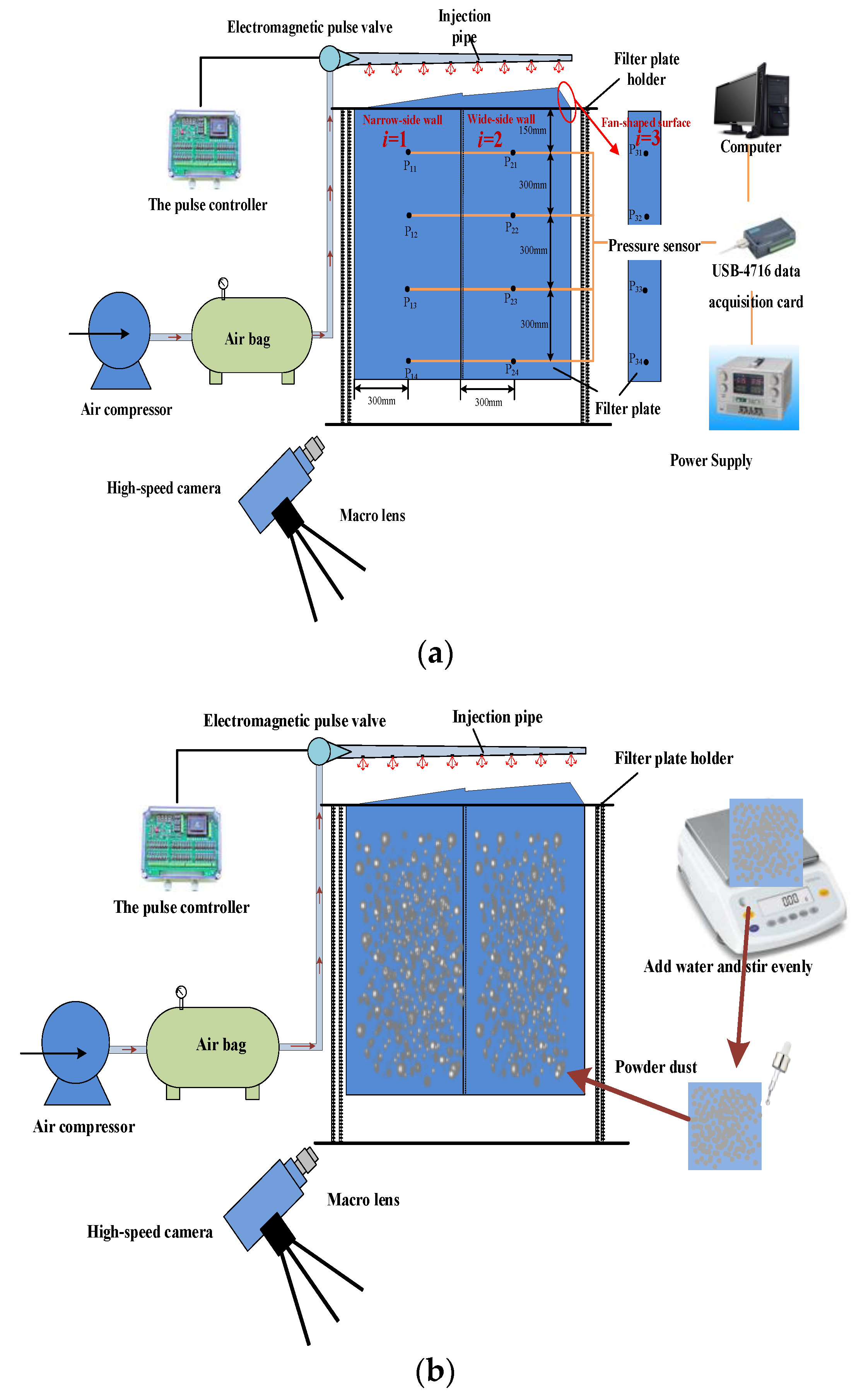
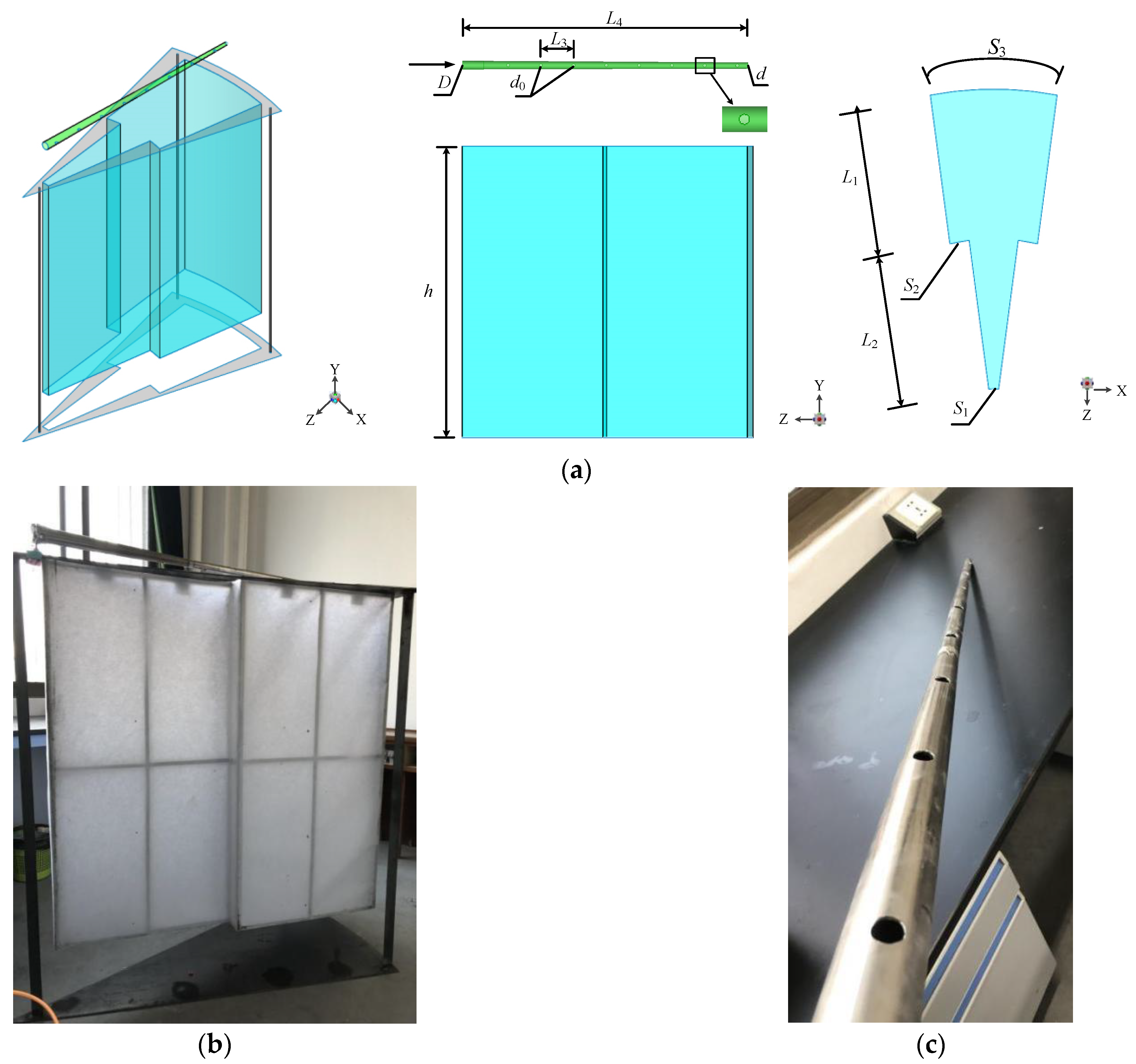
This article studies the dust cleaning performance of the NSMMFP, which is completed on the pulse cleaning test bench, as shown in Figure 1. Figure 1a shows the experimental device diagram and system schematic diagram of the wall surface peak pressure test and Figure 1b shows the device diagram and schematic diagram of the experimental with the powder attached. The NSMMFP applied in this experiment has a built-in support frame, and the frame is covered with a PTFE-coated filter media, the average pore diameter of which is 5 μm, and the porosity is greater than 80%. The blow pipe is a tapered steel pipe produced by a casting process. The injection pipe is a tapered design using a steel pipe produced by a casting process with 8 injection holes; the injection hole spacing is 155 mm. Figure 2 shows the three-dimensional and physical images of the NSMMFP and its injection tube. The specific parameters are displayed in Table 1. This experiment is made up of pulse cleaning and data acquisition systems, including an air compressor (TJ-1200X3, Zhejiang Fushijing Air Compressor Co., Ltd., Zhejiang, China), an air bag, an LXG-16M pulse controller, a DFM-Z-25S electromagnetic pulse valve, a new structure microporous membrane filter plate, a blow pipe, a filter plate holder, a high-speed camera (i-SPEED 716 type, iX Cameras, Rochford, UK), a pressure sensor, an advantech USB-4716 data acquisition card, and a computer with the LabView software (14.0, National Instruments (NI)) installed.
2.2. Experimental Method
In this article, the first experiment is the wall surface peak pressure test, which mainly studies the influence of injection pressure on the wall surface peak pressure of the filter plate using the experimental device shown in Figure 1a. The pressure sensor is utilized to gauge the wall surface peak pressure p0 at 12 testing points (shown in Figure 1a) arranged on the surface of the filter plate during the injection period. The p0 signal through the USB-4716 data acquisition card is transmitted to the computer for synchronous recording. To obtain stable results, each case is conducted more than three times. The collected data are switched to pressure data, which is introduced in our previous study in detail [12]. Then, the experiment of attaching powder to the NSMMFP is carried out, which is mainly divided into two parts: the dust stripping rate test experiment and the dust stripping process observation experiment.
In the dust stripping rate test experiment, we dried the collected dust before the powder attachment experiment started. As shown in Figure 1b, we used an electronic balance to weigh a certain amount of dried dust and added a certain amount of water according to the required dust moisture content, then applied it to the NSMMFP surface after full mixing. We placed the ash hopper and turned on the air compressor to inflate the air bag; when the pressure in the air bag reached the required injection pressure, the injection was carried out. After the injection was completed, the dust collected in the ash hopper was weighed, and the dust stripping rate of the new filter was calculated. In the dust stripping process observation experiment, we took 5 g of wet, evenly stirred, dust and smeared it on the surface of the filter plate, adjusted the lens of the high-speed camera to make the powder area at the center of the shooting area, and shot the whole process of dust stripping during pulse injection. In order to avoid errors caused by experimental equipment and other reasons, each group of working conditions was tested three times and the average value was calculated.
A reasonable selection of experimental conditions should be carried out before the experimental research. First of all, for the injection pressure p, since the filter plate was cleaned by the low-pressure pulse cleaning method, the injection pressure p was selected between 0.15 and 0.35 MPa. For the injection distance X, since the spacing between the new structure microporous membrane filter plates was gradually increasing, the injection distance should have been greater than 38 mm according to the calculation of the jet flow theory. At the same time, some scholars found in the research that the best injection distance of the bag filter for pulse cleaning is 200 mm [26]. Therefore, the injection distance X in this article was selected between 40 and 200 mm. For the dust quality G, it was necessary to consider the quality of the dust attached to the filter media under different filter velocities and operating times of the dust collector, so the dust quality G was selected between 40 and 80 g. Dust moisture content refers to the ratio of moisture in the dust. In this experiment, the moisture content of the collected mine dust measured by the drying method [27] was 1.08%. Therefore, the dust moisture content φ was selected between 1% and 5%. The experimental conditions designed in order to investigate the effect of the low-pressure pulse cleaning effect of the NSMMFP are shown in Table 2.
2.3. Dust Parameters
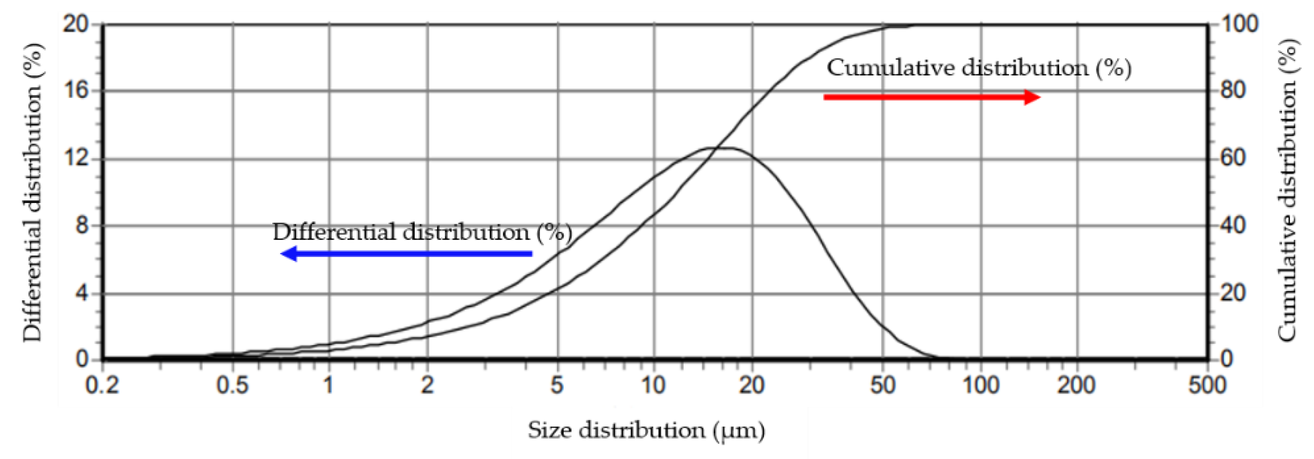
The experimental dust was collected from a mine in southern China. The collected dust was measured by the Zhuhai Omega LS-C (II) laser particle size analyzer. The result is shown in Figure 3, D50 = 11.58 μm, D75 = 19.92 μm. According to the particle size distribution results, the proportion of dust particles with a particle size of less than 19.92 μm was 75%.
3. Results and Discussion
3.1. The Influence of Injection Pressure on the Wall Surface Peak Pressure
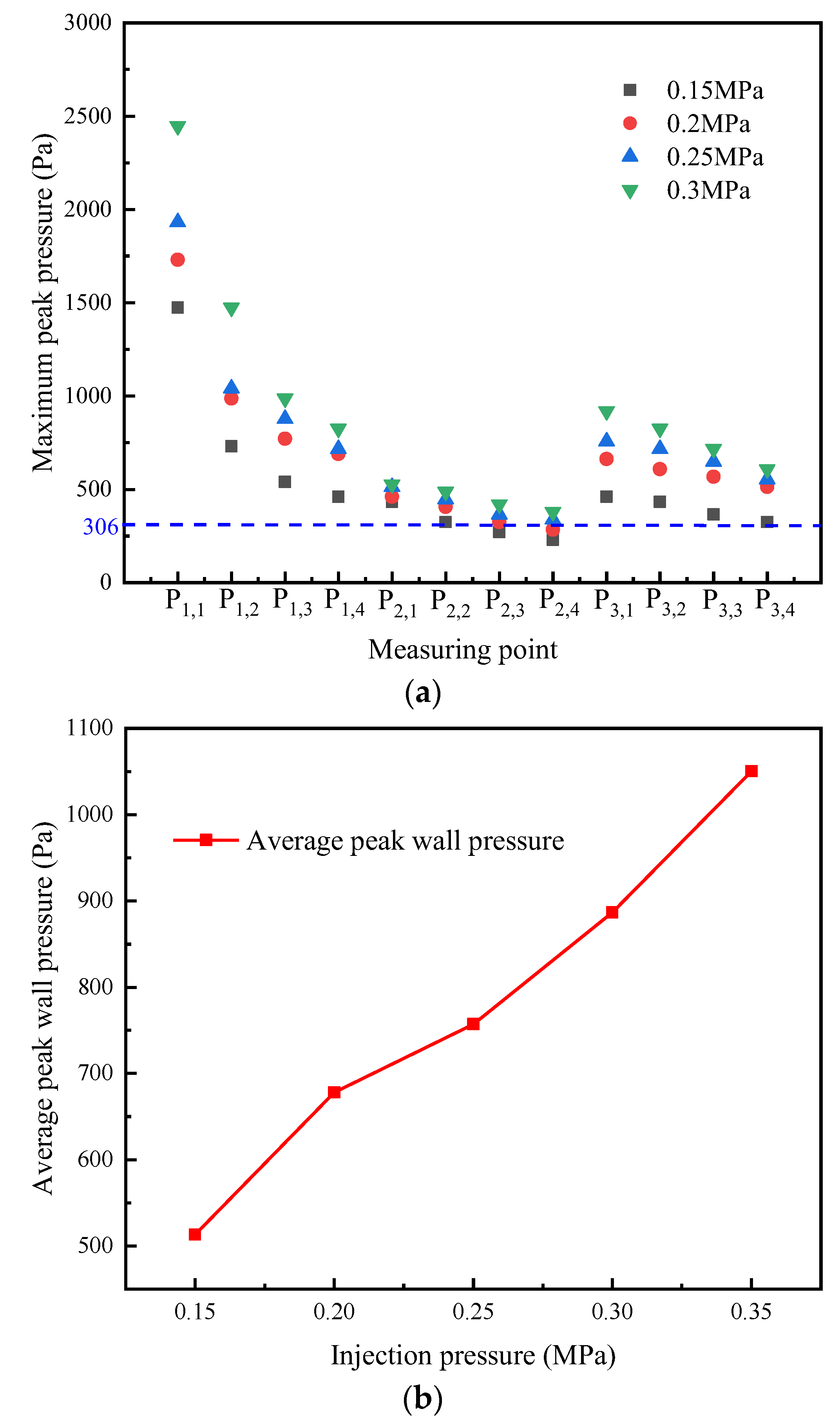
To investigate the influence of the injection pressure p on the peak pressure of the filter plate wall, this study investigated the effect of different injection pressures on the peak pressure of the filter plate wall at an injection distance of X = 40 mm.
Figure 4a shows the maximum wall surface peak pressure at different injection pressures p. As shown in Figure 4a, the maximum wall surface peak pressure at the same measuring point increases with the injection pressure. When p is greater than 0.25 MPa, the pressures of the 12 measuring points are all greater than 306 Pa [12], and when p = 0.15 MPa, only the peak pressures of the measuring points P2,3 and P2,4 are less than 306 Pa. When p = 0.20 MPa, only the peak pressure of P2,4 measuring point is less than 306 Pa, which is 291.46 Pa. Because of the air permeability of the microporous membrane filter media, the blowing air flow diffuses when moving to the bottom of the filter plate. This causes the maximum wall surface peak pressure to gradually decrease from top to bottom along the height of the filter plate starting from 150 mm away from the filter plate mouth. Furthermore, the peak pressure of the narrow side wall where i = 1 is the largest, and the peak pressure of the wide side wall where i = 2 is the smallest. This is because the filter plate spacing on the narrow side is smaller than that of the wide side, so that the impact of airflow on the narrow side filter plate will be greater than that of the wide side filter plate. Furthermore, since the fan-shaped surface where i = 3 is located is relatively closer to the nozzle hole, the peak pressure is larger than that at the wide-surface measuring point. Figure 4b shows the AWSPP of the NSMMFP under different injection pressures. As shown in Figure 4b, in the process of increasing the injection pressure from 0.15 MPa to 0.35 MPa, the AWSPP of the NSMMFP increases linearly from 513.45 Pa to 1050.49 Pa, which has the same trend as the results of Chen et al. [12]. In summary, increasing the injection pressure is beneficial in increasing the wall surface peak pressure of the filter plate, thereby improving the dust cleaning performance of the filter plate.
3.2. The Influence of Injection Pressure on Dust Stripping Rate (DSR)
To investigate the influence of the p on the DSR of the NSMMFP when injection distance X = 40 mm, dust quality G = 40 g, and dust moisture content φ = 2%, the dust stripping of the NSMMFP was studied experimentally at different values of p.
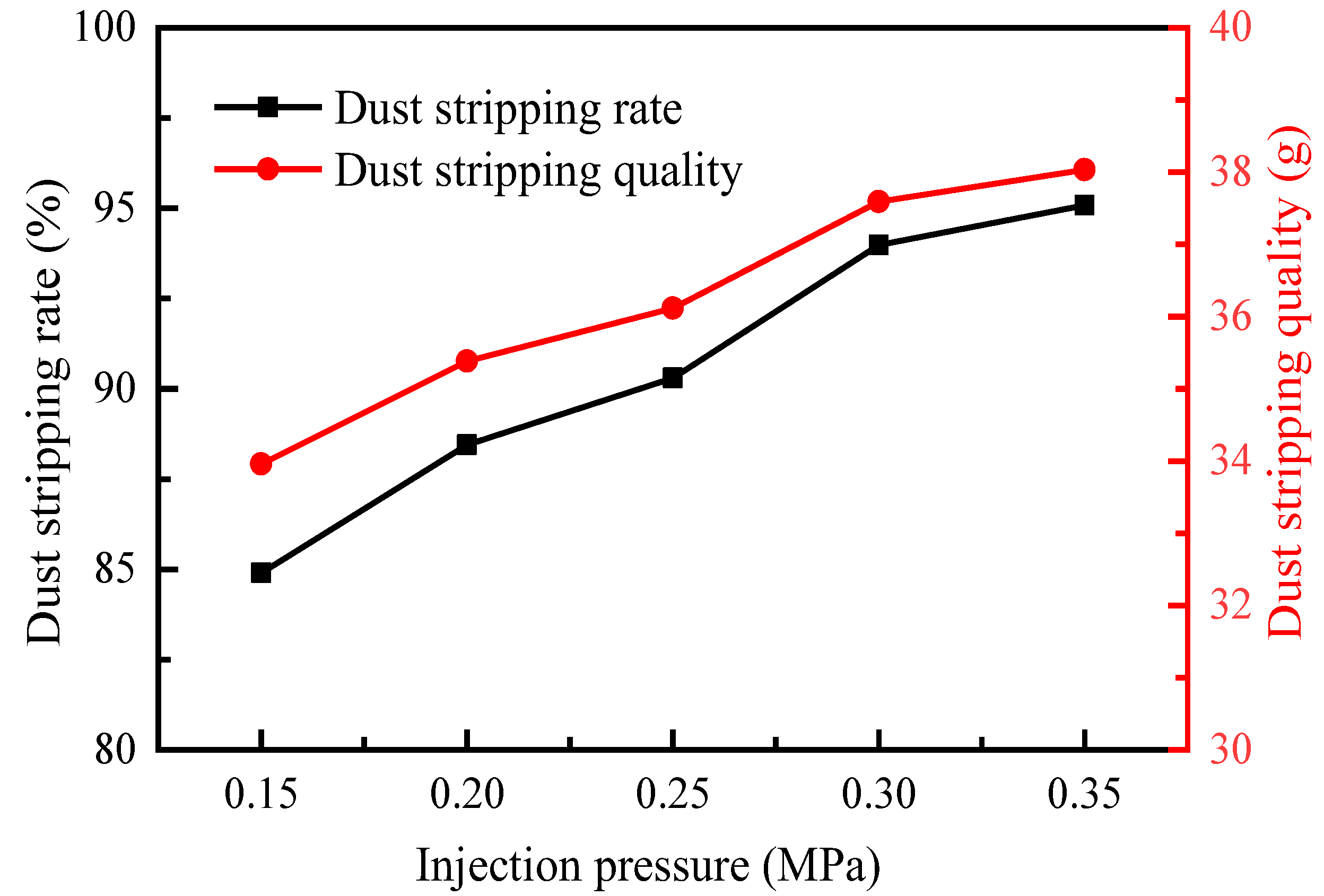
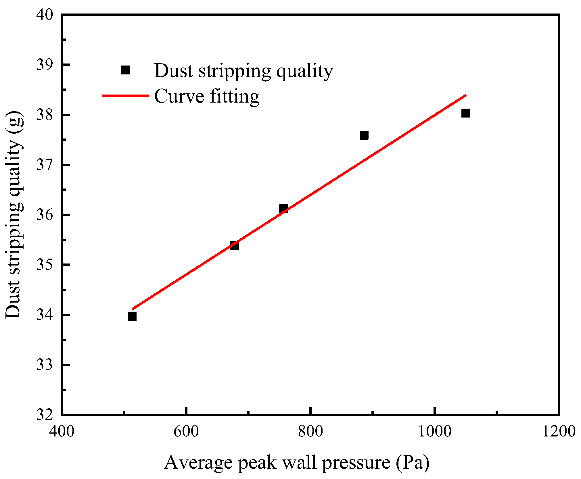
Figure 5 shows the change rule of the DSR of the NSMMFP with the injection pressure. As the injection pressure increases from 0.15 MPa to 0.35 MPa in Figure 5, the dust stripping quality and the dust stripping rate also increase. When p = 0.15 MPa, the dust stripping quality is 33.96 g and the DSR is 84.9%. When the blowing pressure reaches 0.35 MPa, the DSR is 95.08%. The main reason for the analysis is that during the injection process, as p increases, the flow rate of the airflow ejected from the pulse valve expands. The greater the flow rate of the airflow from the nozzle hole, the more airflow is induced to enter the filter plate, thereby effectively improving it. The relationship between the average wall surface peak pressure obtained in Section 3.1 and the dust stripping rate under different injection pressures is obtained; the fitting result is shown in Figure 6 and the fitting formula is shown in Equation (1).
where x is the average wall surface peak pressure (Pa) and y is the quality of dust stripping (g).
The calculation formula of the dust stripping rate is as follows:
where G is the total dust quality. Through comprehensive analysis of Equations (1) and (2), the relationship between the average wall surface peak pressure and dust stripping rate can be obtained.
The fitting results show that the correlation coefficient R2 between the fitted average wall surface peak pressure and the quality of dust stripping is 0.96224, indicating that the fitting is good.
In actual engineering, excessive dust cleaning will lead to a reduction in the life of the filter media of the dust collector or damage to the filter media of the dust collector in severe cases. Zhang et al. [13] experimentally explored the dust cleaning performance of the rectangular pleated filter plate and verified the dust coating powder. The results show that the dust residue is at least 19%, which means that a DSR of 81% is the optimum. Hao et al. [28] found in the research that when the DSR is greater than 70%, normal operation of the dust collector can be guaranteed. Combining the findings in Section 3.1, the subsequent experimental study of the NSMMFP was implemented with the injection pressure p = 0.20 MPa.
3.3. The Influence of Injection Distance on Dust Stripping Rate (DSR)
To investigate the influence of the injection distance X on the DSR of the NSMMFP when injection pressure p = 0.20 MPa, dust quality G = 40 g, and dust moisture content φ = 2%, the dust stripping of the filter plate was studied experimentally at different values of X.
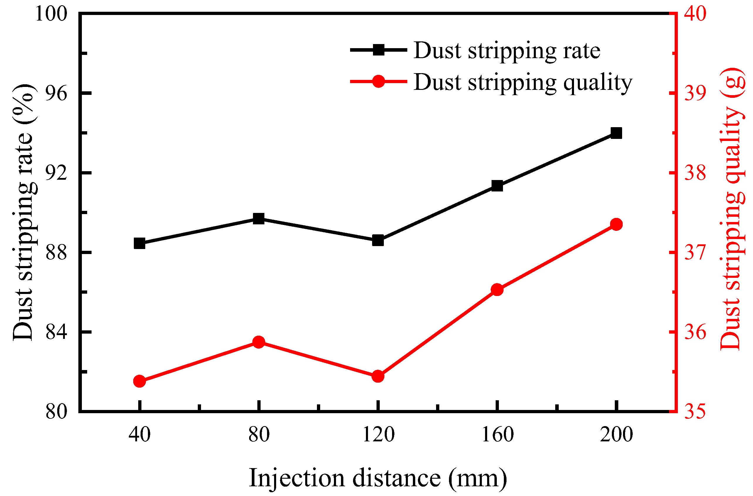
Figure 7 shows the change rule of the DSR of the NSMMFP with the injection distance. When the injection distance increases from 40 mm to 80 mm, the DSR increases from 88.45% to 89.68%. However, when the injection distance increases to 120 mm, the DSR decreases to 88.6%. Through previous simulation research, it was found that as the injection distance increases from 80 mm to 120 mm, due to the diffusion nature of the jet itself, the jet gas of the nozzle begins to diffuse slowly when it does not reach the filter plate mouth, resulting in a change of the peak pressure of the middle and upper wall, and the peak pressure of the monitoring points in the middle and upper part of the filter plate decreases with the increase of the distance. Therefore, the comprehensive numerical simulation results show that the reason for the slight decrease in the dust stripping rate is the process of increasing the injection distance from 80 to 120 mm. When the injection distance continues to increase, the DSR increases to 93.98%, and the dust stripping quality reaches 37.35 g. This is because the increase in the injection distance will affect the dust cleaning effect on the upper part of the filter plate, thereby affecting the DSR of the NSMMFP. On the whole, the DSR increases as the injection distance increases, and the DSR under the five working conditions is greater than 70%. This is because the amount of induced air increases with the injection distance, which can improve the dust cleaning effect of the filter plate to a certain extent. In summary, appropriately increasing the injection distance can improve the dust cleaning effect of the NSMMFP.
3.4. The Influence of Dust Quality on the Dust Stripping Rate (DSR)
To investigate the influence of dust quality G on the DSR of the NSMMFP when injection pressure p = 0.20 MPa, injection distance X = 40 mm, and dust moisture content φ = 2%, the dust stripping rate of the filter plate was studied experimentally at different values of G.
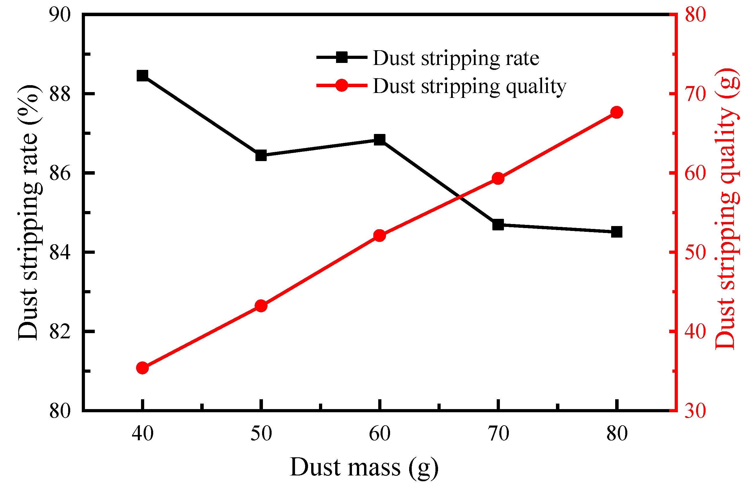
Figure 8 illustrates the change rule of the dust stripping rate of the NSMMFP with the dust quality. The dust stripping rate of the filter plate is on a downward trend as a whole when G increases from 40 g to 80 g, which is from 88.45% to 84.51%. However, when G increased from 50 g to 60 g, the DSR of the filter plate increased slightly. This is due to the increase in dust quality, which causes the thickness and density of the dust layer to increase, which reduces the dust cleaning effect. Zhang et al. [13] found that in the research on the dust residue of the flat frame filter cartridge, the greater the quality of the dust layer, the greater the thickness and density, and the greater the residual amount of dust. To sum up, the greater the dust quality, the worse the dust cleaning effect. Therefore, in order to avoid excessive dust on the wall of the filter plate from affecting the normal operation of the dust collector, it is necessary to clean the dust collector in time.
3.5. The Influence of Dust Moisture Content on Dust Stripping Rate (DSR)
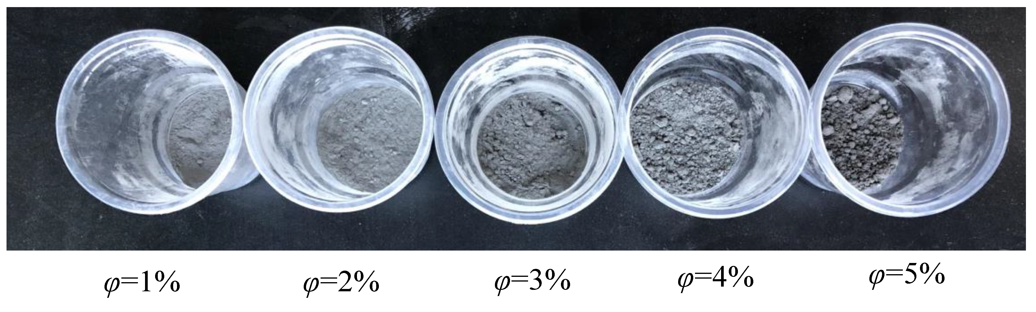
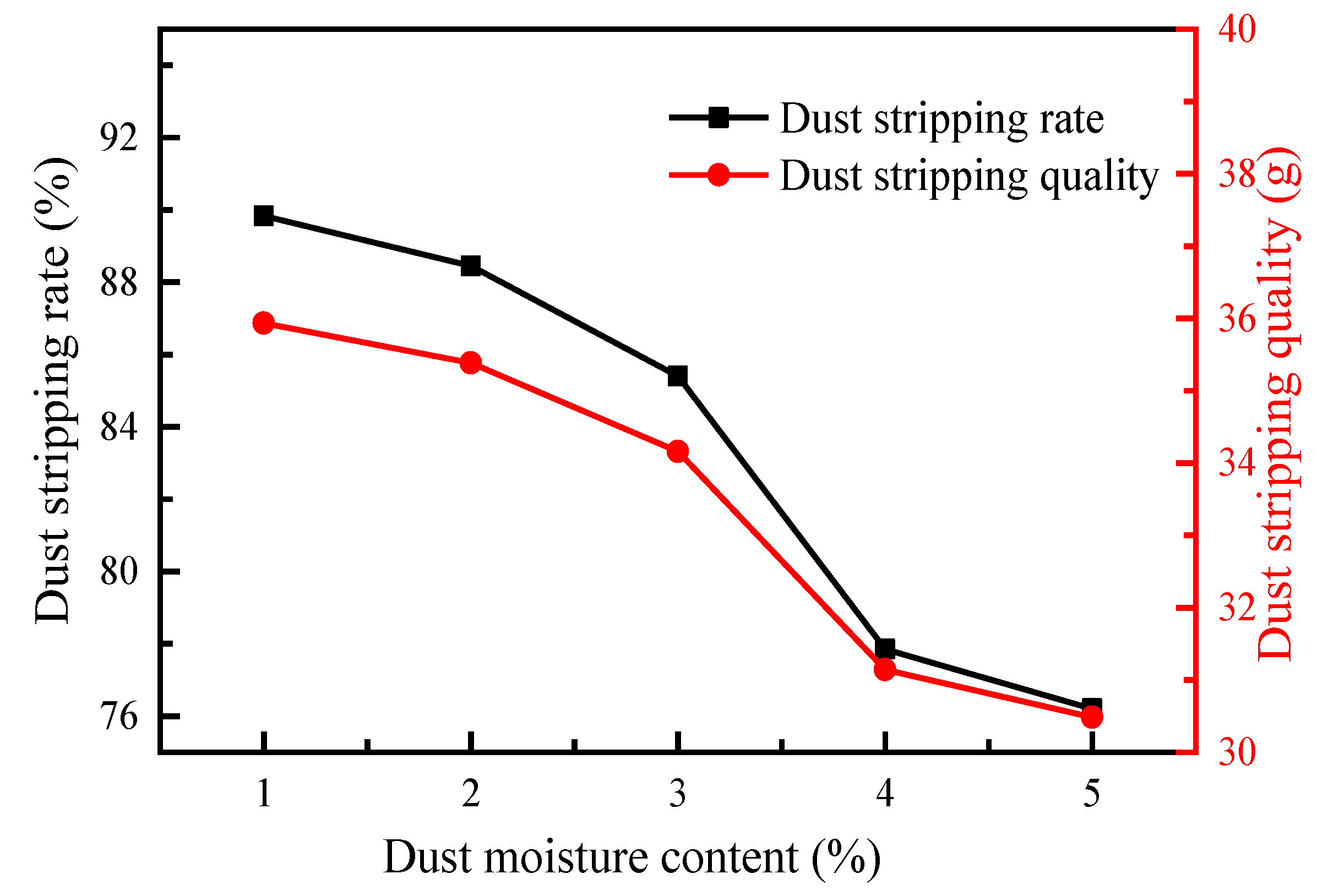
To investigate the influence of the dust moisture content φ on the DSR of the NSMMFP when injection pressure p = 0.20 MPa, injection distance X = 40 mm, and dust quality G = 40 g, the dust stripping rate of the filter plate was studied experimentally at different values of φ. Furthermore, Figure 9 displays the dust particles with different moisture contents.
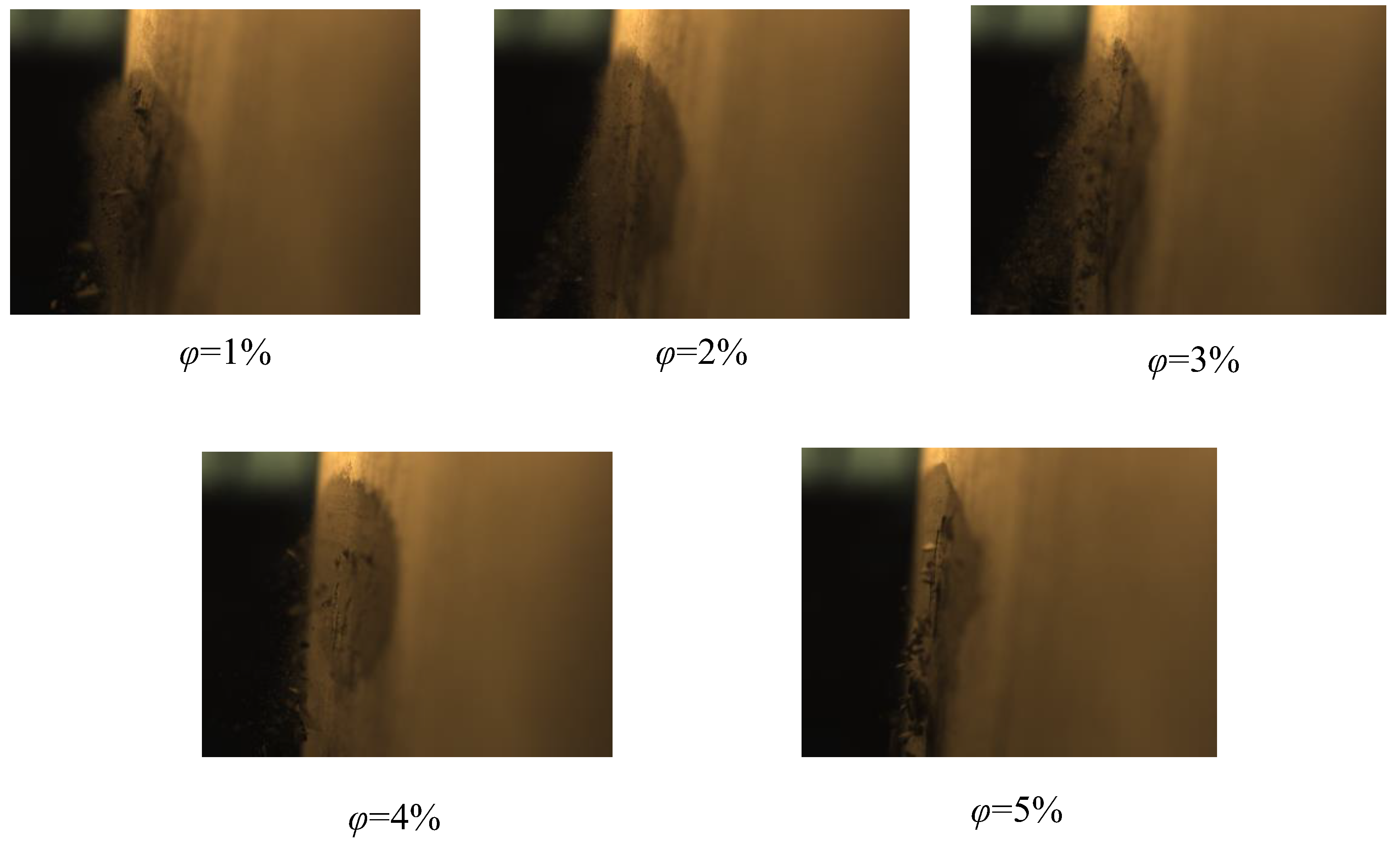
Figure 10 demonstrates the variation of the DSR of the NSMMFP with the moisture content of the dust. When the dust moisture content increases from 1% to 5%, the DSR gradually decreases from 89.83% to 76.2%. This is because the smaller the dust moisture content, the drier the dust particles, so the adhesion between particles and between particles and the filter media is lesser and the dust cleaning effect is better. When the dust moisture content increases, moisture condenses in the dust particle gap, forming a “liquid bridge” at the contact point of the particles, causing a “liquid bridge force” between the particles, resulting in increased adhesion [12,29]; as a result, the DSR is reduced. Figure 11 shows the DSR with different moisture contents during the dust cleaning process taken by the high-speed camera at the same time. It can be seen from the figure that when the dust moisture content is less than 2%, the dust is peeled off in a loose state. When the dust moisture content is 3%, most of the flaked dust is loose dust but a small amount of lumpy dust appears. When the dust moisture content is greater than 4%, due to the increased adhesion force between particles and between particles and filter media, most of the dust peels off in a lumpy state.
3.6. The Process of Dust Flaking
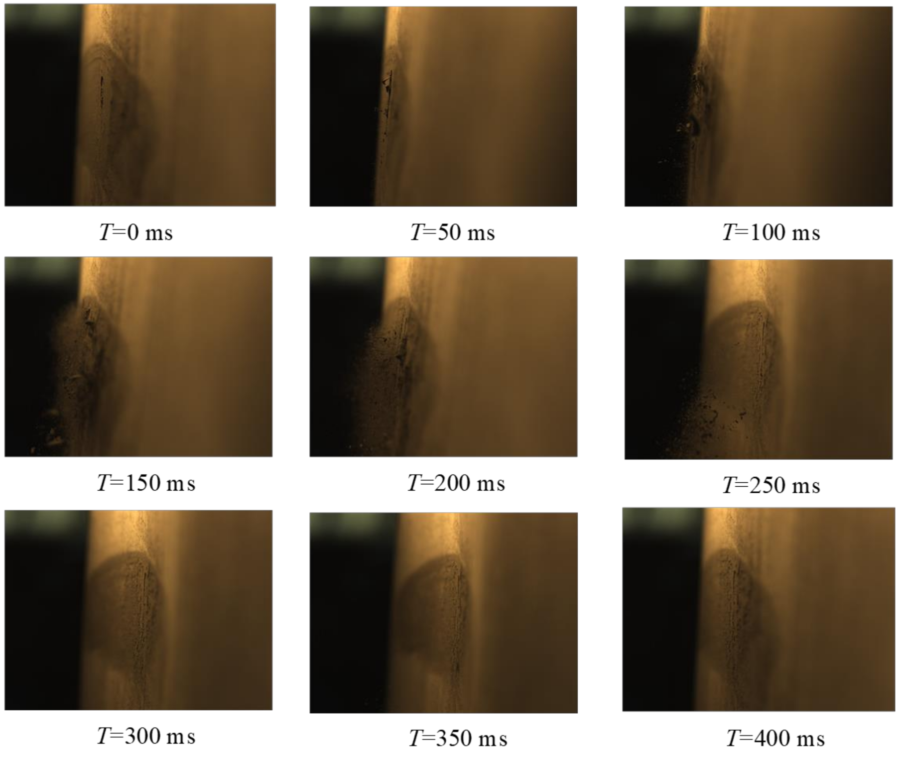
In order to explore the peeling process of dust on the NSMMFP, a high-speed camera was used to shoot the peeling process at injection pressure p = 0.20 MPa, injection distance X = 40 mm and dust moisture content φ = 1%.
Figure 12 shows the flaking state of the dust at different times during the dust cleaning process. From the beginning (T = 0 ms) of spraying, the filter media began to expand from the outside, and at the same time, the dust adhering to the filter media began to crack and peel off from the surface of the filter media. When T = 200 ms, the filter media swelled to the limit. Most of the dust peeled off from the surface of the filter media in the period from T = 0 ms to 200 ms. From T = 250 ms, the filter media began to shrink inward. From T = 250 ms to 400 ms, the filter media also expanded and contracted, but the expansion and contraction amplitude was less than T = 0 ms to 250 ms, and only a small amount of dust peeled from the filter media during this process.
4. Conclusions
In this paper, the dust cleaning performance of a new structure microporous membrane filter plate was studied through experiments, and the effect of the injection pressure on the wall surface peak pressure of the filter plate was explored. The powder attachment experiment was used to explore the relationship between different influencing factors on the dust stripping rate. Moreover, a high-speed camera was used to photograph the peeling state of dust on the filter plate during the pulse cleaning process. The results show:
- (1)
- The wall surface peak pressure gradually decreases from top to bottom along the height of the filter plate from the position 150 mm away from the filter plate mouth. Furthermore, the peak pressure measured on the narrow side is the largest and the wide side is the smallest. The wall surface peak pressure at each measuring point and the average wall surface peak pressure will gradually increase as the injection pressure increases.
- (2)
- The dust stripping quality and the dust stripping rate increase with the injection pressure. Furthermore, the fitting formula of the relationship between the dust stripping quality and the average wall surface peak pressure under the same injection pressure is obtained, and the fitting is good.
- (3)
- As the injection distance increases, the dust stripping quality and dust stripping rate show an overall increasing trend. Furthermore, the dust stripping quality and dust stripping rate gradually decrease as the dust quality and dust moisture content increase.
- (4)
- During the cleaning process, as the dust moisture content increases, the dust attached is more fragmented and peeled from the surface of the filter plate during the cleaning process. Furthermore, the filter media will expand and contract many times, causing the dust to peel off the surface of the filter media.
In future research, we will place the new microporous membrane filter plate in a closed box for powder addition experiments so as to be closer to the practical industrial application. In addition, the influence of the size of the narrow side S1 and wide side S3 of the filter plate on the dust cleaning performance needs to be further studied.
Author Contributions
Data curation, Y.S.; Formal analysis, L.C.; Investigation, L.C. and Z.L.; Methodology, F.Q., Y.H. and J.L.; Resources, F.Q.; Writing—original draft, L.C.; Writing—review & editing, F.Q. All authors have read and agreed to the published version of the manuscript.
Funding
This research was funded by Anhui Provincial Scientific and Technological Major Project grant number 18030801109. And The APC was funded by this fund.
Institutional Review Board Statement
Not applicable.
Informed Consent Statement
Not applicable.
Data Availability Statement
Not applicable.
Conflicts of Interest
The authors declare no conflict of interest.
References
- Li, S.; Zhou, F.; Xie, B.; Wang, F. Influence of injection pipe characteristics on pulse-jet cleaning uniformity in a pleated cartridge filter. Powder Technol. 2018, 328, 264–274. [Google Scholar] [CrossRef]
- Yang, H.; Liu, J.; Jiang, K.; Meng, J.; Guan, D.; Xu, Y.; Tao, S. Multi-objective analysis of the co-mitigation of CO2 and PM2.5 pollution by China’s iron and steel industry. J. Clean. Prod. 2018, 185, 331–341. [Google Scholar] [CrossRef] [Green Version]
- Ren, L.; Zhou, S.; Peng, T.; Ou, X. A review of CO2 emissions reduction technologies and low-carbon development in the iron and steel industry focusing on China. Renew. Sustain. Energy Rev. 2021, 143, 110846. [Google Scholar] [CrossRef]
- Feng, C.; Huang, J.-B.; Wang, M.; Song, Y. Energy efficiency in China’s iron and steel industry: Evidence and policy implications. J. Clean. Prod. 2018, 177, 837–845. [Google Scholar] [CrossRef]
- Lo, L.-M.; Chen, D.-R.; Pui, D.Y.H. Experimental study of pleated fabric cartridges in a pulse-jet cleaned dust collector. Powder Technol. 2010, 197, 141–149. [Google Scholar] [CrossRef]
- Saleh, A.M.; Tafreshi, H.V. A simple semi-numerical model for designing pleated air filters under dust loading. Sep. Purif. Technol. 2014, 137, 94–108. [Google Scholar] [CrossRef]
- Liu, Z.; Chen, L.; Qian, F.; Ye, M.; Wei, M.; Han, Y.; Lu, J. Numerical simulation of dust-cleaning performance of new structure microporous membrane filter plate. Chin. J. Process Eng. 2021, 21, 516–529. [Google Scholar]
- Yan, C.; Liu, G.; Chen, H. Effect of induced airflow on the surface static pressure of pleated fabric filter cartridges during pulse jet cleaning. Powder Technol. 2013, 249, 424–430. [Google Scholar] [CrossRef]
- Qian, Y.; Chen, H.; Dai, H.; Liu, T.; Kuang, T.; Bian, L. Experimental study of the nozzle settings on blow tube in a pulse-jet cartridge filter. Sep. Purif. Technol. 2018, 191, 244–249. [Google Scholar] [CrossRef]
- Li, S.; Xin, J.; Xie, B.; Jin, H.; Hu, S.; Song, S.; Zhou, S.; Zhou, F. Experimental investigation of the optimization of nozzles under an injection pipe in a pulse-jet cartridge filter. Powder Technol. 2019, 345, 363–369. [Google Scholar] [CrossRef]
- Furumoto, K.; Narita, T.; Fukasawa, T.; Ishigami, T.; Kuo, H.-P.; Huang, A.-N.; Fukui, K. Influence of pulse-jet cleaning interval on performance of compact dust collector with pleated filter. Sep. Purif. Technol. 2021, 279, 119688. [Google Scholar] [CrossRef]
- Chen, L.; Qian, F.; Ye, M.; Wei, M.; Han, Y.; Lu, J. Mathematical model of high-humidity dust peeling during pulse-jet cleaning. J. China Coal Soc. 2019, 44, 683–690. [Google Scholar]
- Zhang, M.; Chen, H.; Yan, C.; Li, Q.; Qiu, J. Investigation to rectangular flat pleated filter for collecting corn straw particles during pulse cleaning. Adv. Powder Technol. 2018, 29, 1787–1794. [Google Scholar] [CrossRef]
- Kang, F.; Cheng, H.; Leng, H.; Zen, S.; Xu, Z.; Li, X.; Lǖ, J.; Lin, L.; Chen, H. Performance optimization of rectangular flat pleated filter with slit nozzle for dust cleaning. Powder Technol. 2020, 376, 320–331. [Google Scholar] [CrossRef]
- Shim, J.; Joe, Y.-H.; Park, H.-S. Influence of air injection nozzles on filter cleaning performance of pulse-jet bag filter. Powder Technol. 2017, 322, 250–257. [Google Scholar] [CrossRef]
- Fuping, Q.; Zhe, L.; Mengmeng, Y.; Haitong, W.; Yongjun, X.; Jia, H.; Bowen, C.; Jinli, L.; Wei, D.; Yueheng, Z. Microporous Membrane Dust Collector for Dust Removal Based on Rotary Pulse and Dust Removal. Method. Patent Application NL2025879A, 21 June 2020. [Google Scholar]
- Simon, X.; Chazelet, S.; Thomas, D.; Bémer, D.; Régnier, R. Experimental study of pulse-jet cleaning of bag filters supported by rigid rings. Powder Technol. 2007, 172, 67–81. [Google Scholar] [CrossRef]
- Boudhan, R.; Joubert, A.; Durécu, S.; Gueraoui, K.; le Coq, L. Influence of air humidity on particle filtration performance of a pulse-jet bag filter. J. Aerosol Sci. 2019, 130, 1–9. [Google Scholar] [CrossRef] [Green Version]
- Kurtz, O.; Meyer, J.; Kasper, G. The contribution of small leaks in a baghouse filter to dust emission in the PM2.5 range—A system approach. Particuology 2017, 30, 40–52. [Google Scholar] [CrossRef]
- Lu, H.C.; Tsai, C.J. Influence of Different Cleaning Conditions on Cleaning Performance of Pilot-Scale Pulse-Jet Baghouse. J. Environ. Eng. 2003, 129, 811–818. [Google Scholar] [CrossRef] [Green Version]
- Fukasawa, T.; Kanaoka, C.; Kimura, I.; Bao, L.; Fukui, K. Distributions of fiber mass, air permeability, and filter efficiency in nonwoven fabric bag filters. Chem. Eng. Technol. 2021, 44, 535–541. [Google Scholar] [CrossRef]
- Chen, S.; Wang, Q.; Chen, D.-R. Effect of pleat shape on reverse pulsed-jet cleaning of filter cartridges. Powder Technol. 2017, 305, 1–11. [Google Scholar] [CrossRef]
- Zhang, Q.; Liu, D.; Wang, M.; Shu, Y.; Xu, H.; Chen, H. Characteristics and evaluation index of pulse-jet dust cleaning of filter cartridge. Process Saf. Environ. Prot. 2022, 157, 362–374. [Google Scholar] [CrossRef]
- Chen, S.; Chen, D.-R. Numerical Study of Reverse Multi-Pulsing Jet Cleaning for Pleated Cartridge Filters. Aerosol Air Qual. Res. 2016, 16, 1991–2002. [Google Scholar] [CrossRef] [Green Version]
- Qiu, J.; Wu, D.; Chen, D.-R.; Li, J. Reverse pulsed-flow cleaning of pleated filter cartridges having an inner pleated filter cone. Process Saf. Environ. Prot. 2021, 146, 481–489. [Google Scholar] [CrossRef]
- Zhong, L.; Tan, Z.; Liu, L.; Wang, Z.; Wei, L. Experimental study of dust-cleaning performance of pulse injection on long filter bag. J. Nanchang Univ. 2017, 39, 16–21. [Google Scholar]
- GB/T 16913.7-1997; People’s Republic of China National Standard Dust Physical Properties Test Method Part 7: Determination of Moisture Content-Drying Method. Labor Protection Science and Technology: Shenyang, China, 1998.
- Hao, W.; Shi, W.; Ding, S.; Zhu, N. Mechanism and Design Method of a Dust Cleaning System: Rotary Blowback Bag Filter. J. Northeast. Univ. 2009, 30, 1497–1500. [Google Scholar]
- Xue, Z.; Qian, F.; Zhu, J.; Dong, W.; Han, Y.; Lu, J. Numerical simulation of deposition characteristics for high moisture viscous particles on the surface of polytetrafluoroethylene microporous membrane filtration materials. Chin. J. Process Eng. 2020, 20, 36–45. [Google Scholar]
Figure 1.
Experimental device for the dust cleaning performance of the NSMMFP (a) The experimental device diagram and system schematic diagram of the wall surface peak pressure test. (b) The powder-attached experimental device diagram and principal diagram.
Figure 1.
Experimental device for the dust cleaning performance of the NSMMFP (a) The experimental device diagram and system schematic diagram of the wall surface peak pressure test. (b) The powder-attached experimental device diagram and principal diagram.

Figure 2.
Model of the NSMMFP and injection pipe. (a) Three-dimensional map of the NSMMFP and injection pipe. (b) Physical picture of the NSMMFP. (c) Physical picture of injection pipe.
Figure 2.
Model of the NSMMFP and injection pipe. (a) Three-dimensional map of the NSMMFP and injection pipe. (b) Physical picture of the NSMMFP. (c) Physical picture of injection pipe.

Figure 3.
Dust particle size distribution.

Figure 4.
The effect of injection pressure on the wall surface peak pressure. (a) The maximum peak pressure of each measuring point under different injection pressures. (b) The average wall surface peak pressure (AWSPP) of the under different injection pressures.
Figure 4.
The effect of injection pressure on the wall surface peak pressure. (a) The maximum peak pressure of each measuring point under different injection pressures. (b) The average wall surface peak pressure (AWSPP) of the under different injection pressures.

Figure 5.
The effect of injection pressure on dust stripping rate (DSR).

Figure 6.
The relationship between the average wall surface peak pressure (AWSPP) and dust stripping quality.
Figure 6.
The relationship between the average wall surface peak pressure (AWSPP) and dust stripping quality.

Figure 7.
The effect of injection distance on dust stripping rate (DSR).

Figure 8.
The effect of dust quality on dust stripping rate (DSR).

Figure 9.
Dust particles with different moisture contents.

Figure 10.
The effect of dust moisture content on dust stripping rate (DSR).

Figure 11.
Dust peeling state under different dust moisture content.

Figure 12.
The peeling state of dust at different injection times.


Table 1.
The related parameters of the NSMMFP and injection pipe.
| Parameters | Value | |||||
|---|---|---|---|---|---|---|
| Filter plate size (mm) | L1 | L2 | S1 | S2 | S3 | h |
| 600 | 600 | 40 | 78.30 | 510.40 | 1200 | |
| Injection pipe parameters (mm) | L3 | L4 | D | d | d0 | |
| 155 | 1450 | 40 | 16 | 15 | ||
| Number of nozzles | 8 | |||||
| SEM image of the surface of the membrane filter |  | |||||
Table 2.
The NSMMFP conditions setting.
| Parameter Setting of Wall Surface Peak Pressure Experiment | ||||||
|---|---|---|---|---|---|---|
| Influencing factors | Injection pressure p (MPa) | 0.15 | 0.20 | 0.25 | 0.30 | 0.35 |
| Parameter setting of attached powder experiment | ||||||
| (1) the dust stripping rate test experiment | ||||||
| Influencing factors | Injection pressure p (MPa) | 0.15 | 0.20 | 0.25 | 0.30 | 0.35 |
| Injection distance X (mm) | 40 | 80 | 120 | 160 | 200 | |
| the dust quality G (g) | 40 | 50 | 60 | 70 | 80 | |
| Dust moisture content φ (%) | 1 | 2 | 3 | 4 | 5 | |
| (2) the dust stripping process observation experiment | ||||||
| Influencing factors | Dust moisture content φ (%) | 1 | 2 | 3 | 4 | 5 |
Publisher’s Note: MDPI stays neutral with regard to jurisdictional claims in published maps and institutional affiliations. |
© 2022 by the authors. Licensee MDPI, Basel, Switzerland. This article is an open access article distributed under the terms and conditions of the Creative Commons Attribution (CC BY) license (https://creativecommons.org/licenses/by/4.0/).
Share and Cite
MDPI and ACS Style
Chen, L.; Liu, Z.; Sun, Y.; Qian, F.; Han, Y.; Lu, J. Experimental Study on the Dust-Cleaning Performance of New Structure Microporous Membrane Filter Plate. Atmosphere 2022, 13, 817. https://0-doi-org.brum.beds.ac.uk/10.3390/atmos13050817
AMA Style
Chen L, Liu Z, Sun Y, Qian F, Han Y, Lu J. Experimental Study on the Dust-Cleaning Performance of New Structure Microporous Membrane Filter Plate. Atmosphere. 2022; 13(5):817. https://0-doi-org.brum.beds.ac.uk/10.3390/atmos13050817
Chicago/Turabian StyleChen, Lumin, Zhe Liu, Yi Sun, Fuping Qian, Yunlong Han, and Jinli Lu. 2022. "Experimental Study on the Dust-Cleaning Performance of New Structure Microporous Membrane Filter Plate" Atmosphere 13, no. 5: 817. https://0-doi-org.brum.beds.ac.uk/10.3390/atmos13050817
Note that from the first issue of 2016, this journal uses article numbers instead of page numbers. See further details here.