Design of Terrace Drainage Networks Using UAV-Based High-Resolution Topographic Data


1
Department of Land, Environment, Agriculture and Forestry, University of Padova, 35020 Legnaro (PD), Italy
2
Department of Civil & Environmental Engineering, University of Connecticut, Storrs, CT 06269, USA
*
Author to whom correspondence should be addressed.
†
Current address: COMAB—Cooperative Society, Via Santellone 37, 25018 Montichiari (BS), Italy.
‡
Current address: Institute for the Advanced Study of Sustainability, United Nations University, Tokyo 150-8925, Japan.
Water 2019, 11(4), 814; https://0-doi-org.brum.beds.ac.uk/10.3390/w11040814
Submission received: 14 March 2019
/
Revised: 5 April 2019
/
Accepted: 9 April 2019
/
Published: 18 April 2019
(This article belongs to the Special Issue Terraced Landscapes and Hydrological-Geological Hazards)
Abstract
:Hillslope viticulture has a long history in Mediterranean Europe, and still holds important cultural and economic value. Steep hillsides have widely been levelled by terraces, in order to control surface water flow and facilitate cultivation. However, under unsustainable management and growing rainfall aggressiveness, terraced vineyards have become one of the most erosion-prone agricultural landscapes. The Valcamonica valley in Lombardy (Italy) presents a typical example of an ancient wine production region where rural land abandonment has previously caused widespread degradation of the traditional terracing systems. Recently, a local revival of wine production led to restoration plans of the terraces and their drainage functioning, to safeguard productivity and hydrogeologic safety. In this study, an Unmanned Aerial Vehicle (UAV) survey was carried out to reconstruct an accurate and precise 3D terrain model of a Valcamonica vineyard through photogrammetry. The resulting high-resolution topographic data allowed insights of surface flow-induced soil erosion patterns based on the Relative Path Impact Index (RPII). Three diverse drainage networks were designed and digitally implemented, allowing scenario analysis of the costs and benefits in terms of potential erosion mitigation. The presented methodology could likely improve the time-efficiency and cost-effectiveness of similar restoration plans in degraded landscapes.

1. Introduction
Agricultural terraces are among the most evident anthropogenic signatures and dominant drivers of the geomorphology of our time [1,2]. Designed to control water flow and infiltration for facilitating hillslope agriculture, the construction of terraces is an ancient practice still found all over the world [3]. However, terrace degradation is worsening due to modern developments, such as the abandonment of rural areas and consequent lack of maintenance [4,5], increased pressure from machinery traffic [6], unsuitable terrace design and expansions [1] and changing rainfall patterns [7]. These factors contribute to hydrogeologic risks, such as soil erosion and nutrient loss or even terrace collapse, landslides and debris flows [8,9,10,11].
In Mediterranean Europe, vineyard terraces represent one of the most severely degrading landscape types [12,13,14], with high potential for cultural and economic losses (e.g., tourism, landscape services, productivity and employment). The intricate landscape pattern of vineyards, farms, villages and small towns provide a cultural heritage, the quality and management of which have been recently promoted by several international initiatives. Most notable among these are the United Nations Educational, Scientific and Cultural Organization (UNESCO) World Heritage Sites or the Globally Important Agricultural Heritage Systems (GIAHS) by the Food and Agriculture Organization (FAO) [15].
The Valcamonica valley at the foothills of the Italian Alps represents a typical example of an ancient terraced vineyard production system. Currently, the wine production industry is being restored after a period of widespread abandonment [16]. Land degradation is evident as the old terraced systems have been widely overgrown, eroded and collapsed [17]. Precise and accurate topographic information is of key importance for a structural design of terrace systems, in order to safeguard their drainage functioning and mitigating hydrogeologic risks in the face of increasing high-intensity rainstorms [18].
Developments in computational power and the use of image-based Structure-from-Motion (SfM) complementing Multi-View Stereo (MVS) photogrammetry [19] allow for the survey of 3D topography from Unmanned Aerial Vehicle (UAVs) imagery [20] or even smartphone imagery [21,22]. Compared to laser altimetry (LiDAR), this provides a more affordable opportunity for the construction of high-resolution Digital Elevation Models (DEMs) for relatively small-scale applications, such as agricultural plots [23]. Consequently, UAVs and SfM-MVS approaches have been used for terrace management in recent studies, for example, [24,25,26]. The purpose of this paper is to apply such technology to digitally reconstruct terrace morphology and to allow the design and evaluation of several drainage networks, in support of vineyard terrace maintenance in Valcamonica. The work considers the Relative Path Impact Index (RPII) [27] to indicate runoff-induced erosion patterns and to provide an evaluation of the drainage design.
2. Materials and Methods
2.1. Study Area
The study area is a terraced vineyard of ~3 ha located in the Valcamonica valley, Brescia Province, in the northern Italian region of Lombardy (Figure 1a, 45°52’28.75” N; 10°9’18.45” E). This valley has a long tradition of viticulture on levelled hillslopes, dating back for centuries [28]. However, the 1950s showed a rural exodus from this area causing degradation of the abandoned terraces [16], which was slightly countered over last decade with the establishment of the Valcamonica wine consortium and geographical quality designation [17]. The studied site is located on a relatively steep hillside close to the valley bottom, with an average slope of 48% and elevations ranging between 304 m and 384 m a.s.l. (based on a topographic survey described in Section 2.2). It contains a series of heavily degraded dry-stone wall terraces, which have recently undergone clearing and reconstruction work by landowners, although terrace failure remains evident (Figure 1b,c). At the time of the survey, the lower central part consisted mostly of newly constructed terraces with low soil cover, situated just upstream of a large commercial zone, emphasising the importance of hydrogeologic safety (Figure 1a). The eastern and western sections of the study area, on the other hand, consist mostly of established vineyard terraces with inter-row grass cover. Dominant soil types found in the area are endoleptic cambisols [29], and the lithology is characterised by a sandstone sedimentary rock layer up to 600 m depth, as well as quartziferous ignimbrites from volcanic source with a depth up to 70 m [30]. The climate of the valley is relatively wet, with annual precipitation sums ranging between 1200 mm and 1400 mm [31]. According to climate projections for the next century, Valcamonica is situated in a climate change hotspot with expected winter precipitation of +5% to +30% through global multi-model ensembles [32] or even exceeding +40% in regional projections [18]. With this prospect, it is crucial to map the current state of Valcamonica terraces in order to understand their hydrologic functioning and risks and to develop a suitable drainage design.
2.2. Unmanned Aerial Vehicle Survey and Structure-from-Motion Photogrammetry
The aerial survey in this study was carried out using a 3-kg quadcopter (Mesodrone Srl., San Gillio, Italy; Figure 2a), equipped with a Sony® RX 100 Mark 3 camera (Sony®, Tokyo, Japan) with Zeiss lens of 20 MP (fixed focal length of 8.8 mm, sensor size 23.2 × 15.4 mm; Zeiss, Oberkochen, Germany). The flight was operated manually following a conventional overlapping pattern while capturing ~700 pictures (maintaining a >80% front overlap and >60% side overlap). Flight altitude ranged between 50 m and 70 m, resulting in a Ground Sampling Distance (GSD) of 0.027–0.038 m. Sixteen Ground Control Points (GCPs, 0.8 × 0.8 m panels with contrasting colours) were distributed over the study area, of which Differential Global Positioning System (DGPS) coordinates were recorded using a TopCon HiPer V station (Synergy Positioning Systems Ltd., Auckland, New Zealand; Figure 2b) in the WGS84-UTM32N spatial reference system (ESPG 32632). The imagery was processed with an SfM-MVS approach using photogrammetric software (Agisoft Photoscan v1.2.4.2336). Briefly, this process comprises five main steps: (i) camera precalibration using Agisoft Lens v0.4.2 in order to minimise image distortion; (ii) image alignment, by identification of images with common features, and reconstruction of a 3D scene without a spatial scale information; (iii) adding absolute GCP positions to the image processing in order to improve the accuracy of the model and georeferencing it; (iv) optimisation of image alignment; (v) dense cloud reconstruction. The photogrammetric process provided an orthophoto for visual inspection and a 3D point cloud for further terrain analysis. Finally, vegetation points were removed where possible (using CloudCompare GPL v2.7 freeware) and a Digital Terrain Model (DTM) of the study area was created (Figure 2c) with a cell size of 0.2 m and a vertical accuracy of 0.044 m (Root Mean Square Error of DTM and DGPS measurements). The accuracy and the precision of this dataset were suitable for the application of the Relative Path Impact Index when compared to the developers original work [27,33] based on several DTMs derived by airborne and terrestrial laser scanning (ALS and TLS) with respective horizontal resolutions of 0.5–1.0 m and 0.2 m, and related vertical accuracies of 0.15–0.3 m and 0.01–0.1 m. In addition, any residual error related to the photogrammetric processing was inherently consistent throughout the drainage scenarios that are presented in this study.
2.3. Relative Path Impact Index
The Relative Path Impact Index (RPII) indicates preferential runoff pathways created by artificial landscape features (e.g., hillside roads or terraces) through a comparison of contributing drainage areas including or excluding those morphologic features [27]. The logarithmic form of the index highlights the areas with strong drainage alterations, which indicate concentration points of potential surface water runoff and subsequent soil erosion:
where Ar represents the drainage area of the hillslope in its current, artificially modified state, while Asm represents the drainage area on a smoothed hillslope, without artificial terraces. The methodology of Tarolli et al. [33] was adopted, in which the drainage areas were calculated in GIS software using the flow direction algorithm [34]. The original DTM was smoothed using a quadratic approximation proposed by Evans [35]:
where Z, x and y represent the local coordinates, while a to f are the quadratic coefficients, here solved by a moving window of 71 m following the approach by Wood [36].
RPII = ln((Ar − Asm)/Asm)
Z = ax2 + by2 + cxy + dx + ey + f
2.4. Drainage Networks Designs
Three drainage networks were designed for the Valcamonica study area with varying ditch types, dimensions, spatial designs and resulting costs (Figure 3). The design and placement were based on the generated DTM and a feasibility assessment from field observations. Primarily, two rectangular cross-sectional dimensions were used: a minor ditch type of 0.2 × 0.2 m and a major ditch type of 0.4 × 0.4 m (based on the dimensions of existing networks in the surroundings, while respecting DTM grid size). Furthermore, we simulated different spatial designs (Figure 3): Network I consisted of roughly 1200 m of minor ditches placed along the terrace dry-stone wall fronts recurring every ~10 m of elevation difference (vertical drainage densities in Figure 3), fitted to the existing terrace morphology. Network II consisted of an identical network with major cross-sectional dimensions, which was alternated with an additional network of minor dimensions, resulting in a terrace drain every ~5 m of elevation difference. In this scenario, step-drains were placed across sloping paths with a ~2 m interval (minor dimensions) to intercept accumulated runoff along the paths. Network III was identical to Network II, but with added roadside ditches (major dimensions) that aim to collect intercepted runoff from the step-drains. Additionally, in Network III, the minor terrace ditches were roughly doubled in density, resulting in a terrace drain every ~3 m of elevation difference. All drainage network scenarios were designed and carved into the original DTM following the procedure of Tarolli et al. [33]. Sample transect profiles after the carving are displayed in Figure 3.
The cost-analysis in this study was based on a fixed price indication for manual excavation of €173.30/m3 as provided by local authorities [37], serving as a relative approximation to add an exploratory economic component to the evaluation of the drainage networks.
Evaluation of the drainage impact was done both visually (supported by field-observations and the orthophoto) and quantitatively. Two approaches were used for numerical comparison across scenarios: (i) zonal sums of positive RPII values, reflecting the overall runoff potential and (ii) the zonal number of cells with critical RPII values, based on the threshold of > found by Tarolli et al. [33]. In the latter, the standard deviation from the original RPII map was used as a reference for further comparison.
3. Results and Discussion
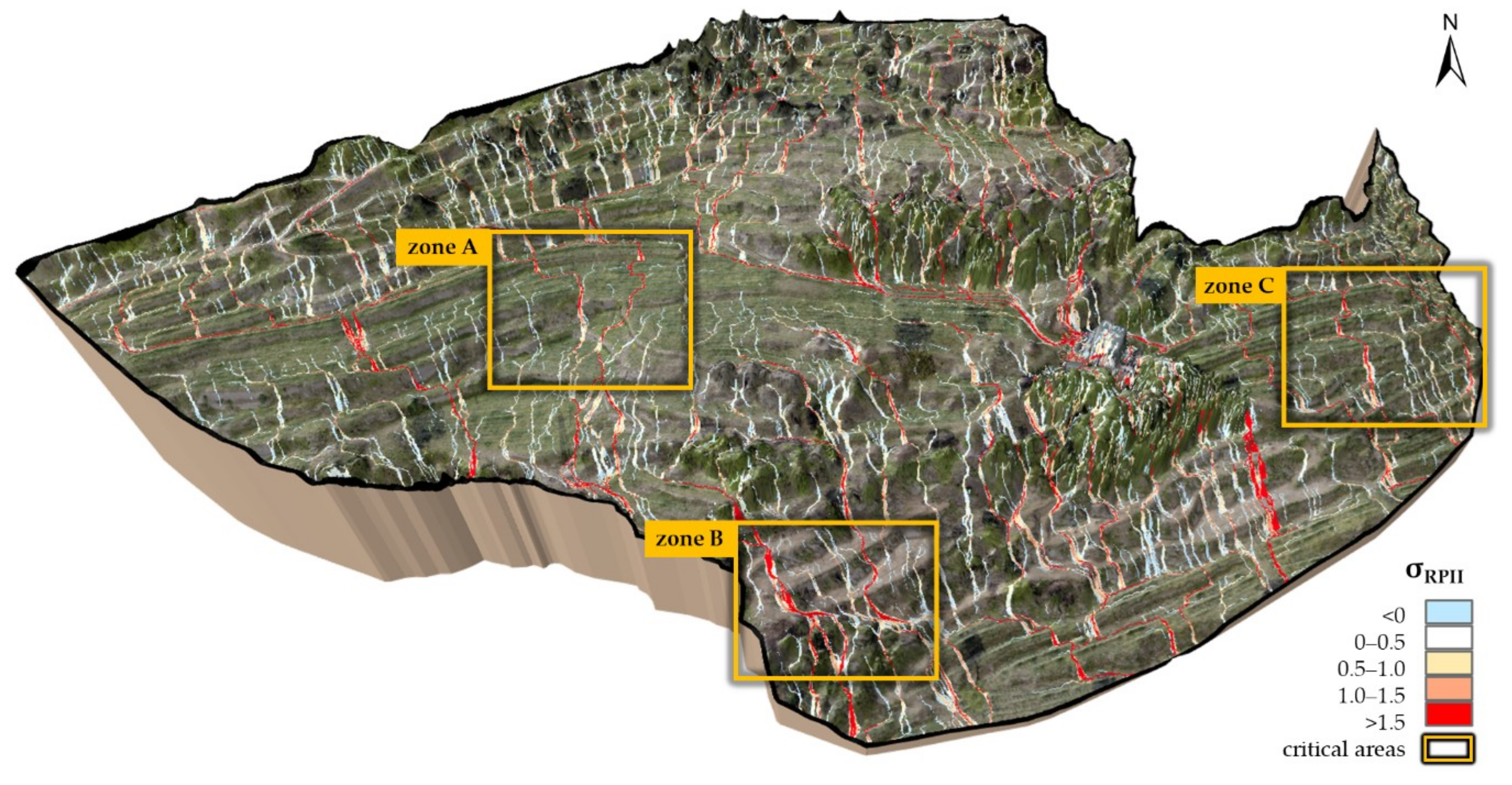
Figure 4 shows the RPII calculated for the Valcamonica study area in its current state. Critical zones (>, reddish colours) are typically related to flow concentration by roads and terraces, and subsequent release at topographic interruptions, increasing the risk of soil erosion. Three critical zones (Figure 4, zones A–C) are highlighted for comparison of potential flow concentration and the effect of the different drainage network scenarios. The selection of these zones was based on the presence of critical patterns and field evidence of terrace damages (not considering the central part for possible disturbance by remaining vegetation).
3.1. Visual Analysis
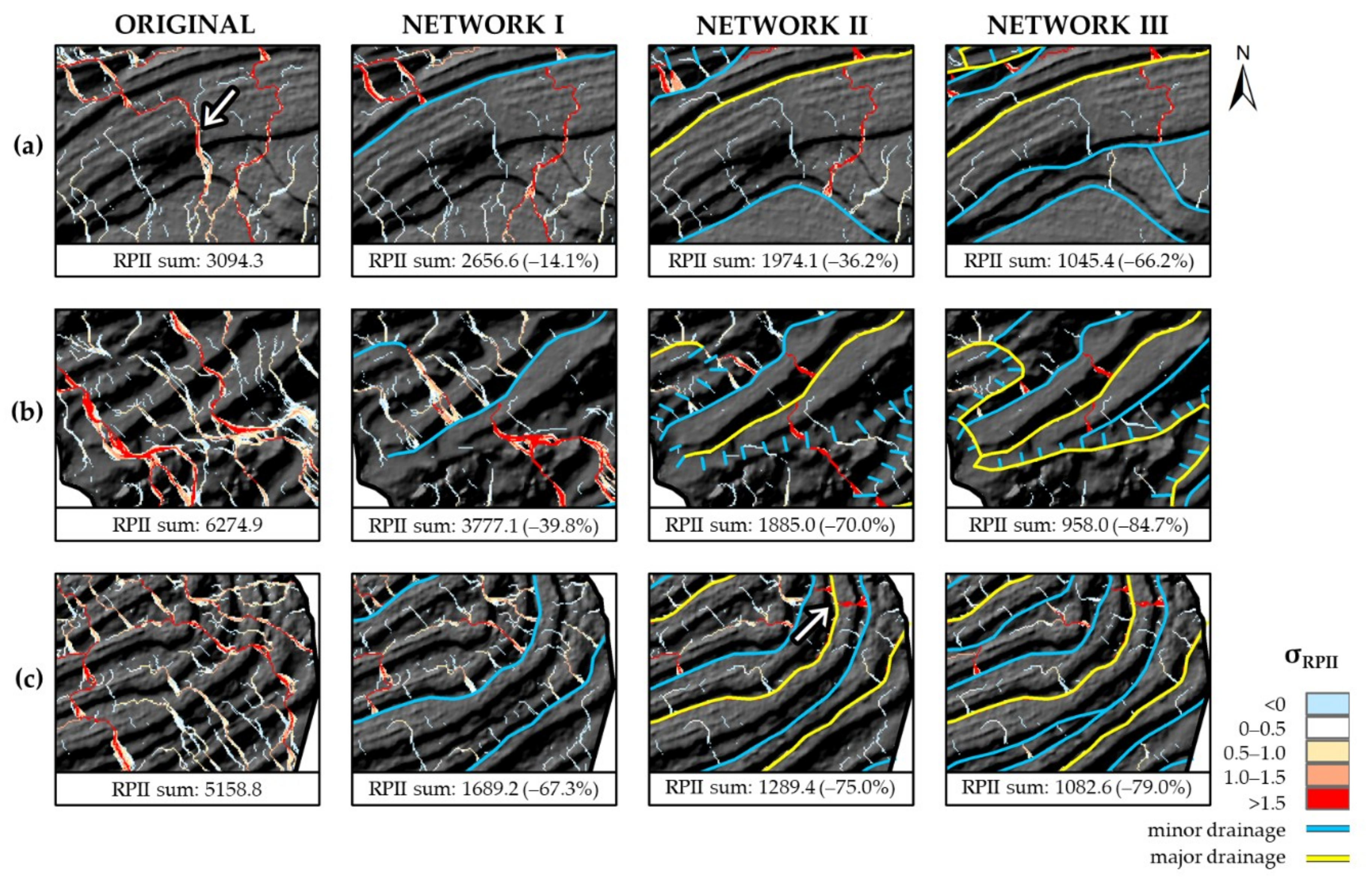
Zone A is characterised by established grape cultivation on relatively gentle slopes and wide terraces. Typically, such circumstances can enhance infiltration, which, however, with poor maintenance or design may threaten the structural integrity of terrace walls and cause collapse. RPII patterns found indicate an upstream concentration of potential surface flow, draining to the location of a field-observed terrace failure (Figure 1c, situated at the white arrow in Figure 5a). A minor drainage ditch, such as that of Network I, successfully intercepts this preferential flow path, although the ditch spills in a local depression a few meters eastwards, hence merely shifting the problem (Figure 5a, second panel). The major drainage dimensions of Network II are also not sufficient to prevent this release (Figure 5a, third panel), suggesting that the terrace morphology is such that water flow stagnates at this point (i.e., even after 0.4 m of carving). The improved drainage density of Network III partly mitigates this problem by intercepting the flow pathway at the next terrace step downstream (Figure 5a, fourth panel). However, a closer analysis and possibly a field inspection are recommended to guarantee the safeguarding of this point.
Zone B is situated at the downstream part of the study area and is, therefore, naturally more exposed to upstream flow concentration. The importance of proper management of this zone is emphasised by the fact that a large commercial zone is located directly downhill (see Figure 1a) and by the presence of bare soil terraces due to recent reconstruction (Figure 4, zone B). An intense rainfall event could trigger surface runoff causing in situ soil loss and possibly contribute to ex situ sediment deposition. The implementation of the minor terrace drainage of Network I scenario locally reduces the potential flow concentration (Figure 5b, second panel), although, similar to the previous example, water flow is likely released at ditch ends and in other lower points. As before, this cannot be prevented by the major drainage dimensions, but the only effective design is that with an increased drainage density, for example, Network II and III, that would allow upstream interception of these flows (Figure 5b, third and fourth panels). In this zone, critical RPII values are also found along the road. The step-drains of Network II are effective for intercepting this path, although roadside ditches of Network III are essential to control the drainage of the collected water flow (Figure 5b, fourth panel).
Zone C represents a section of the study area with established vineyard terraces on a steep slope and dense terracing. High RPII values, although more equally distributed than the previous zone, indicate several situations of potential flow accumulation across the terraces. The minor drainage system of Network I effectively reduces the overall RPII values, without showing signs of drainage runoff release (Figure 5c, second panel). Networks II and III continue to intercept flow formation at shorter intervals (Figure 5c, third and fourth panels). However, uncontrolled flow concentration can appear where the drainage placement or dimensions are inappropriate (e.g., Figure 5c, third panel, white arrow). This illustrates the general risk that comes with artificial drainage control, that is, the interception of minor surface water flows along the length of the terrace, which may accumulate and exceed the network capacity and consequently be released in large proportions. With unsuitable design, drainage ditches could thus play the same triggering role that mountain roads and terraces are known to do in erosion and landslide activation [38,39,40].
3.2. Numerical Analysis
Zonal RPII sums and relative changes are given for each network in Figure 5 map subscripts. Cumulative RPII values do not carry any physical meaning, but they allow for a non-biased scenario comparison (as they are not sensitive to the changing number of non-void cells). Original values show much higher RPII values in zones B and C compared to zone A (Figure 5, first panels). This is followed by sharp reductions with Network I in these two zones (Figure 5, second panels), particularly zone C with –67.3%. This is likely a result of the homogeneous terrace features of this zone, which benefit significantly from even a relatively simple drainage system. Zone B, on the other hand, requires the implementations related to Network II in order to achieve such a reduction (Figure 5, third panels), due to the higher complexity of landscape features.
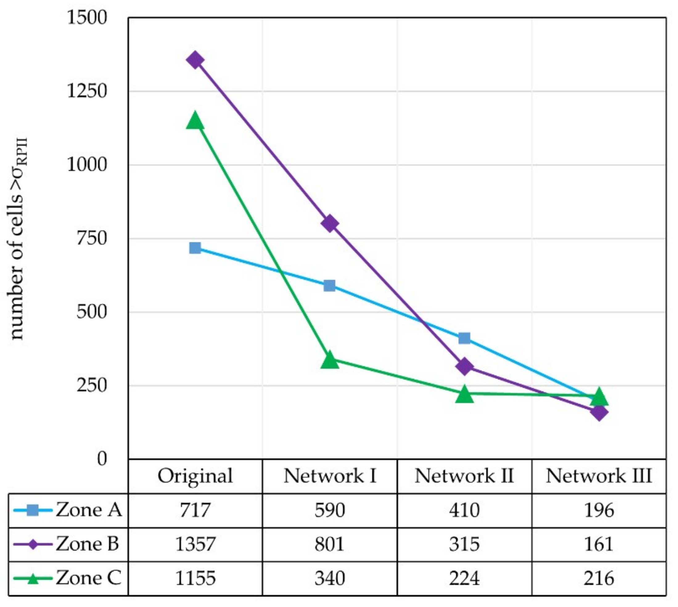
Where cumulative RPII values give an indication of overall potential flow concentration, the analysis of critical RPII values reveals the impact specifically on the mitigation of extremes. As discussed, cell values > can be considered critical; and for each zone and scenario, the number of critical cells is displayed in Figure 6. In perspective of the total number of cells inside each zone (26928), it stands out how zones B and C have a rather high initial coverage of extreme RPII values (~4% to 5% of total surface). The impact of the drainage networks on extremes shows a similar reduction pattern to that of the cumulative RPII values shown in Figure 5. The graph of Figure 6 illustrates the sharp drop of critical concentration values in zone C under Network I (i.e., a lower number of cells exceeding ), while the more advanced networks have limited effect. Zone B shows an equally moderate response to Networks I and II. Zone A initially has the lowest coverage of critical RPII values (~2.7%), but it requires the advanced Network III in order to reduce this number to the level of, for example, zone C, with a final coverage of 0.6–0.8% at all zones (72.7–88.1% reduction in respect to the original coverage).
In numerical terms, it is clear that an optimal reduction strategy is different across zones. Critical RPII values in zone C drop only with a subsequent 10% and 0.7% with a doubled or tripled vertical drainage density (respectively, Network II and III). From the visual assessment, we observed that new critical concentrations were in fact caused by these specific networks. Such situations raise the question whether the design should either: (i) be up-scaled, with larger dimensions and better spatial connectivity for discharging or (ii) have a lower density, allowing small-scale flow formation in order to prevent large-scale water concentration in certain sections. Eventually, the final design depends on the available investment capital and, moreover, a cost-benefit analysis for the different scenarios.
3.3. Cost-Benefit Analysis and Discussion
Simple cost estimations for excavation show a clear variation among the scenarios (Figure 3), almost reaching one order of magnitude. As Network I comprises only minor ditches (0.2 × 0.2 m), the costs of €8336 are relatively low. Network II, with doubled drainage density and length, results in higher costs of €43,325, due to the quadrupling of the cross-sectional area in parts of the network (minor to major, i.e., 0.2 × 0.2 to 0.4 × 0.4 m). Further expansions of Network III result in cost estimation of €65,091. In terms of benefit, the previous sections have pointed out several examples where network expansion did not necessarily yield substantial profits, for example, at zone C after Network I. Contrastingly, certain critical issues could not efficiently be resolved, e.g., where topographic depressions exist on terrace benches, and a careful redesign supported by field inspection is encouraged in this case. Economic benefits could be quantified in further studies, for example, by estimating the saved costs related to soil loss and terrace reconstruction.
These insights can offer a reference as a starting point of iterative design and evaluation. A rapid and simple index, such as RPII, can play a valuable role in this phase while minimising time and investments required for extensive field experiments. The same can be said more generally about the use of UAV imagery and image-based photogrammetry for digital terrain analysis of terraced landscapes [41]. With the new opportunities offered by a UAV and SfM-MVS based methodology, surveying costs are much lower than before [23]. The use of UAVs also adds flexibility in surveying strategies, such as higher photographic overlap or inclusion of oblique imagery, for features that are difficult to capture [42]. As such, restoration projects in degraded landscapes can be favoured by the development of these techniques, offering also practical and user-friendly tools to a wider group of land managers.
4. Conclusions
This study emphasises the potential of high-resolution topography data from low-cost UAVs and image-based photogrammetry to digitally reconstruct terrace system morphology and facilitate the design of their drainage systems. Particularly in the restoration of degraded vineyard terraces, such as found in Valcamonica, Lombardy (Italy), there is a need for accessible methods to safeguard proper hydrologic functioning of the terrace and drainage system, in the light of potential increasing occurrence of heavy rainstorms. The high-resolution DTM (0.2 m) allowed an accurate and precise representation of the surface flow-induced soil erosion patterns using the Relative Path Impact Index (RPII), matching field observations. It also allowed the virtual implementation of different drainage network scenarios and an evaluation of their effectiveness. Scenario analyses illustrate the mitigation potential of terrace and roadside drainage ditches with various dimensions and placement, and points out the possible risk related to unsuitable designs (i.e., the creation of new hazards due to uncontrolled surface flow release). A simple cost evaluation shows how different drainage system scenarios have strong financial implications, which emphasises the need for an iterative design process and cost-benefit analysis to find an optimal solution. The presented methodology can thus play a key role in the design phase of similar projects, by providing rapid tools for preliminary design evaluation. This may likely improve time-efficiency and cost-effectiveness of maintenance and restoration plans for degraded landscapes.
Author Contributions
Conceptualization by P.T. and M.T.; methodology, investigation, formal analysis, data curation by A.P., M.T. and G.S.; writing—original draft preparation by A.P.; writing—review and editing by A.P., G.R., G.S. and P.T.; visualization by A.P.; supervision by P.T.
Funding
This study was partly supported by project ViTE “Vineyard Terraced landscapes: understanding the Environmental constraints to improve sustainable managements”, funded by the Linda Scattolin research program at TESAF department of the University of Padova (Italy).
Acknowledgments
The authors would like to express gratitude to the Tedeschi brothers for making their vineyards available to serve as a study area for this research and to Zenith Aerial Solutions Srl. for providing the UAV service that made this study available.
Conflicts of Interest
The authors declare no conflict of interest.
References
- Tarolli, P.; Preti, F.; Romano, N. Terraced landscapes: From an old best practice to a potential hazard for soil degradation due to land abandonment. Anthropocene 2014, 6, 10–25. [Google Scholar] [CrossRef]
- Wei, W.; Chen, D.; Wang, L.; Daryanto, S.; Chen, L.; Yu, Y.; Lu, Y.; Sun, G.; Feng, T. Global synthesis of the classifications, distributions, benefits and issues of terracing. Earth Sci. Rev. 2016, 159, 388–403. [Google Scholar] [CrossRef]
- Johnson, D.L.; Lewis, L.A. Land Degradation: Creation and Destruction; Rowman & Littlefield: Oxford, UK, 1995; ISBN 0-631-19244-1. [Google Scholar]
- García-Ruiz, J.M.; Lana-Renault, N. Hydrological and erosive consequences of farmland abandonment in Europe, with special reference to the Mediterranean region—A review. Agric. Ecosyst. Environ. 2011, 140, 317–338. [Google Scholar] [CrossRef]
- Lesschen, J.P.; Cammeraat, L.H.; Nieman, T. Erosion and terrace failure due to agricultural land abandonment in a semi-arid environment. Earth Surf. Process. Landforms 2008, 33, 1574–1584. [Google Scholar] [CrossRef]
- Pijl, A.; Barneveld, P.; Mauri, L.; Borsato, E.; Grigolato, S.; Tarolli, P. Impact of mechanisation on soil loss in terraced vineyard landscapes. Cuad. Investig. Geogr. 2019, 45, 287–308. [Google Scholar] [CrossRef]
- Monjo, R.; Martin-Vide, J. Daily precipitation concentration around the world according to several indices. Int. J. Climatol. 2016, 36, 3828–3838. [Google Scholar] [CrossRef]
- Gallart, F.; Llorens, P.; Latron, J. Studying the role of old agricultural terraces on runoff generation in a small Mediterranean mountainous basin. J. Hydrol. 1994, 159, 291–303. [Google Scholar] [CrossRef]
- Crosta, G.B.; Dal Negro, P.; Frattini, P. Soil slips and debris flows on terraced slopes. Nat. Hazards Earth Syst. Sci. 2003, 3, 31–42. [Google Scholar] [CrossRef]
- Preti, F.; Errico, A.; Caruso, M.; Dani, A.; Guastini, E. Dry-stone wall terrace monitoring and modelling. Land Degrad. Dev. 2018, 29, 1806–1818. [Google Scholar] [CrossRef]
- Preti, F.; Guastini, E.; Penna, D.; Dani, A.; Cassiani, G.; Boaga, J.; Deiana, R.; Romano, N.; Nasta, P.; Palladino, M.; et al. Conceptualization of Water Flow Pathways in Agricultural Terraced Landscapes. Land Degrad. Dev. 2018, 29, 651–662. [Google Scholar] [CrossRef]
- Maetens, W.; Vanmaercke, M.; Poesen, J.; Jankauskas, B.; Jankauskiene, G.; Ionita, I. Effects of land use on annual runoff and soil loss in Europe and the Mediterranean: A meta-analysis of plot data. Prog. Phys. Geogr. 2012, 36, 599–653. [Google Scholar] [CrossRef]
- Kosmas, C.; Danalatos, N.; Cammeraat, L.H.; Chabart, M.; Diamantopoulos, J.; Farand, R.; Gutierrez, L.; Jacob, A.; Marques, H.; Martinez-Fernandez, J.; et al. The effect of land use on runoff and soil erosion rates under Mediterranean conditions. Catena 1997, 29, 45–59. [Google Scholar] [CrossRef]
- Cerdan, O.; Govers, G.; Le Bissonnais, Y.; Van Oost, K.; Poesen, J.; Saby, N.; Gobin, A.; Vacca, A.; Quinton, J.; Auerswald, K.; et al. Rates and spatial variations of soil erosion in Europe: A study based on erosion plot data. Geomorphology 2010, 122, 167–177. [Google Scholar] [CrossRef]
- Dela-Cruz, M.J.; Koohafkan, P. Globally important agricultural heritage systems: A shared vision of agricultural, ecological and traditional societal sustainability. Resour. Sci. 2009, 31, 905–913. [Google Scholar]
- Bonardi, L.; Varotto, M. Paesaggi Terrazzati d’Italia: Eredità Storiche e Nuove Prospettive; Franco Angeli: Milano, Italy, 2016; ISBN 9788891743435. (In Italian) [Google Scholar]
- Flocchini, E.; Putelli, A. Alla scoperta dei vini IGT di Valle Camonica. Comun. Mont. Val. Camonica 2014, 5–71. Available online: http://www.saporidivallecamonica.it/uploads/docs/54e2faf147e3f.pdf (accessed on 15 April 2019). (In Italian).
- Gao, X.; Pal, J.S.; Giorgi, F. Projected changes in mean and extreme precipitation over the Mediterranean region from a high resolution double nested RCM simulation. Geophys. Res. Lett. 2006, 33. [Google Scholar] [CrossRef]
- Eltner, A.; Kaiser, A.; Castillo, C.; Rock, G.; Neugirg, F.; Abellán, A. Image-based surface reconstruction in geomorphometry-merits, limits and developments. Earth Surf. Dyn. 2016, 4, 359–389. [Google Scholar] [CrossRef]
- Giordan, D.; Hayakawa, Y.; Nex, F.; Remondino, F.; Tarolli, P. Review article: The use of remotely piloted aircraft systems (RPASs) for natural hazards monitoring and management. Nat. Hazards Earth Syst. Sci. 2018, 18, 1079–1096. [Google Scholar] [CrossRef]
- Sofia, G.; Masin, R.; Tarolli, P. Prospects for crowdsourced information on the geomorphic ‘engineering’ by the invasive Coypu (Myocastor coypus). Earth Surf. Process. Landforms 2017, 42, 365–377. [Google Scholar] [CrossRef]
- Micheletti, N.; Chandler, J.H.; Lane, S.N. Investigating the geomorphological potential of freely available and accessible structure-from-motion photogrammetry using a smartphone. Earth Surf. Process. Landforms 2015, 40, 473–486. [Google Scholar] [CrossRef]
- Nex, F.; Remondino, F. UAV for 3D mapping applications: A review. Appl. Geomat. 2014, 6, 1–15. [Google Scholar] [CrossRef]
- Peter, K.D.; D’Oleire-oltmanns, S.; Ries, J.B.; Marzolff, I.; Ait Hssaine, A. Soil erosion in gully catchments affected by land-levelling measures in the Souss Basin, Morocco, analysed by rainfall simulation and UAV remote sensing data. Catena 2014, 113, 24–40. [Google Scholar] [CrossRef]
- Diaz-Varela, R.A.; Zarco-Tejada, P.J.; Angileri, V.; Loudjani, P. Automatic identification of agricultural terraces through object-oriented analysis of very high resolution DSMs and multispectral imagery obtained from an unmanned aerial vehicle. J. Environ. Manag. 2014, 134, 117–126. [Google Scholar] [CrossRef] [PubMed]
- Wei, Z.; Han, Y.; Li, M.; Yang, K.; Yang, Y.; Luo, Y.; Ong, S.H. A Small UAV Based Multi-Temporal Image Registration for Dynamic Agricultural Terrace Monitoring. Remote Sens. 2017, 9, 904. [Google Scholar] [CrossRef]
- Tarolli, P.; Calligaro, S.; Cazorzi, F.; Fontana, G.D. Recognition of surface flow processes influenced by roads and trails in mountain areas using high-resolution topography. Eur. J. Remote Sens. 2013, 46, 176–197. [Google Scholar] [CrossRef]
- Sangiorgi, F. Muri a Secco e Terrazzamenti nel Parco dell’Adamello: Linee Guida per il Recupero; Branduini, P., Ed.; Parco dell’Adamello: Novara, Italy, 2007; ISBN 8878771244. (In Italian) [Google Scholar]
- Costantini, E.A.C.; L’Abate, G.; Barbetti, R.; Fantappiè, M.; Lorenzetti, R.; Magini, S. Carta dei Suoli d’Italia, Scala 1:1.000.000; Consiglio per la ricerca e la sperimentazione in agricoltura (CRA): Firenze, Italy, 2012. (In Italian) [Google Scholar]
- Presbitero, M.; Piccin, A. Carta Geologica d’Italia dai Rilevamenti Geologici 1:25.000—Foglio 078 Breno; Istituto Superiore per la Protezione e la Ricerca Ambientale (ISPRA): Rome, Italy, 2009. (In Italian) [Google Scholar]
- Ceriani, M.; Carelli, M.; Agnelli, U.; Bodio, N.; Colombo, S.; Lauzi, S.; Martelli, M. Carte delle precipitazioni annue—Meteo Val San Martino. Available online: http://meteovalsanmartino.weebly.com/carte-precipitazioni-annue.html (accessed on 10 November 2017). (In Italian).
- Coppola, E.; Giorgi, F. An assessment of temperature and precipitation change projections over Italy from recent global and regional climate model simulations. Int. J. Climatol. 2010, 30, 11–32. [Google Scholar] [CrossRef]
- Tarolli, P.; Sofia, G.; Calligaro, S.; Prosdocimi, M.; Preti, F.; Dalla Fontana, G. Vineyards in terraced landscapes: New opportunities from lidar data. Land Degrad. Dev. 2015, 26, 92–102. [Google Scholar] [CrossRef]
- Tarboton, D.G. A new method for the determination of flow directions and upslope areas in grid digital elevation models. Water Resour. Res. 1997, 33, 309–319. [Google Scholar] [CrossRef]
- Evans, I.S. An Integrated System of Terrain Analysis and Slope Mapping: Final Report. Z. Geomorphol. 1979, 36, 274–295. [Google Scholar]
- Wood, J.D. The Geomorphological Characterisation of Digital Elevation Models; University of Leicester: Leicester, UK, 1996. [Google Scholar]
- Provincia di Brescia. Prezzario Manutenzione Fabbricati Provinciali Opere Edili; Area Tecnica E Dei Trasporti, Settore Interventi Sul Patrimonio, Edilizia Scolastica, Sicurezza Sul Lavoro: Brescia, Italy, 2015. (In Italian) [Google Scholar]
- Borga, M.; Tonelli, F.; Selleroni, J. A physically based model of the effects of forest roads on slope stability. Water Resour. Res. 2004, 40, 1–11. [Google Scholar] [CrossRef]
- Tarolli, P. Humans and the Earth’s surface. Earth Surf. Process. Landforms 2016, 41, 2301–2304. [Google Scholar] [CrossRef]
- Wemple, B.C.; Swanson, F.J.; Jones, J.A. Forest roads and geomorphic process interactions, Cascade Range, Oregon. Earth Surf. Process. Landforms 2001, 26, 191–204. [Google Scholar] [CrossRef]
- Colomina, I.; Molina, P. Unmanned aerial systems for photogrammetry and remote sensing: A review. ISPRS J. Photogramm. Remote Sens. 2014, 92, 79–97. [Google Scholar] [CrossRef]
- Dai, R.; Fotedar, S.; Radmanesh, M.; Kumar, M. Quality-aware UAV coverage and path planning in geometrically complex environments. Ad Hoc Netw. 2018, 73, 95–105. [Google Scholar] [CrossRef]
Figure 1.
(a) Study area as situated in the Valcamonica valley (Google Earth snapshot, yellow outline), and its location in Italy (inset map); (b,c) examples of field-observed terrace failure present in the study area (photographs by M. Tosoni).
Figure 1.
(a) Study area as situated in the Valcamonica valley (Google Earth snapshot, yellow outline), and its location in Italy (inset map); (b,c) examples of field-observed terrace failure present in the study area (photographs by M. Tosoni).

Figure 2.
(a) Mesodrone quadcopter Unmanned Aerial Vehicle (UAV) used for aerial surveying; (b) Topcon HiPer V Differential Global Positioning System (DGPS) device for the registration of Ground Control Point (GCP) positions; (c) Digital Terrain Model (DTM) derived through SfM-MVS based photogrammetry.

Figure 3.
Technical specifications of the proposed drainage networks. Spatial designs, transects, dimensions and estimated costs are compared for each network. Based on spatial analysis by the authors and labour rates provided by Provincia di Brescia [37].
Figure 3.
Technical specifications of the proposed drainage networks. Spatial designs, transects, dimensions and estimated costs are compared for each network. Based on spatial analysis by the authors and labour rates provided by Provincia di Brescia [37].

Figure 4.
Study area Relative Path Impact Index (RPII) map computed for current conditions (original terrain), highlighting three critical zones that were selected for detailed analysis of preferential surface flow and drainage network evaluation (zones A–C).
Figure 4.
Study area Relative Path Impact Index (RPII) map computed for current conditions (original terrain), highlighting three critical zones that were selected for detailed analysis of preferential surface flow and drainage network evaluation (zones A–C).

Figure 5.
(a–c) Relative Path Impact Index (RPII) maps computed for current conditions (original) and for three drainage scenarios (Networks I–III) for zones A–C, respectively. For each combination, summed positive RPII values are displayed along with the relative change in respect to the original state in percentage.

Figure 6.
Number of cells with value >σRPII for each zone and drainage scenario, showing the mitigating effect of critical Relative Path Impact Index (RPII) values by the drainage networks (total number of cells per zone equals to 26928).
Figure 6.
Number of cells with value >σRPII for each zone and drainage scenario, showing the mitigating effect of critical Relative Path Impact Index (RPII) values by the drainage networks (total number of cells per zone equals to 26928).

© 2019 by the authors. Licensee MDPI, Basel, Switzerland. This article is an open access article distributed under the terms and conditions of the Creative Commons Attribution (CC BY) license (http://creativecommons.org/licenses/by/4.0/).
Share and Cite
MDPI and ACS Style
Pijl, A.; Tosoni, M.; Roder, G.; Sofia, G.; Tarolli, P. Design of Terrace Drainage Networks Using UAV-Based High-Resolution Topographic Data. Water 2019, 11, 814. https://0-doi-org.brum.beds.ac.uk/10.3390/w11040814
AMA Style
Pijl A, Tosoni M, Roder G, Sofia G, Tarolli P. Design of Terrace Drainage Networks Using UAV-Based High-Resolution Topographic Data. Water. 2019; 11(4):814. https://0-doi-org.brum.beds.ac.uk/10.3390/w11040814
Chicago/Turabian StylePijl, Anton, Michele Tosoni, Giulia Roder, Giulia Sofia, and Paolo Tarolli. 2019. "Design of Terrace Drainage Networks Using UAV-Based High-Resolution Topographic Data" Water 11, no. 4: 814. https://0-doi-org.brum.beds.ac.uk/10.3390/w11040814
Note that from the first issue of 2016, this journal uses article numbers instead of page numbers. See further details here.