Article

Estimation of Scour Propagation Rates around Pipelines While Considering Simultaneous Effects of Waves and Currents Conditions

by
Mohammad Najafzadeh
1,*,
Giuseppe Oliveto
2 and
Farshad Saberi-Movahed
3
1
Department of Water Engineering, Faculty of Civil and Surveying Engineering, Graduate University of Advanced Technology, Kerman P.O. Box 76315-116, Iran
2
School of Engineering, University of Basilicata, 85100 Potenza, PZ, Italy
3
College of Engineering, North Carolina State University, Raleigh, NC 22606, USA
*
Author to whom correspondence should be addressed.
Submission received: 28 April 2022 / Revised: 7 May 2022 / Accepted: 13 May 2022 / Published: 16 May 2022

Abstract

:
Seabed offshore pipelines are widely applied to carry fluid over long distances of the seafloor. The design of offshore pipelines is conducted to bear quite a few environmental loading circumstances in order to provide a well-guarded and reliable fluid transition. Fluid leakage and pipeline vibration due to a failure of the pipeline are the prime causes of accidental catastrophes. Scour phenomena occur around offshore pipelines due to currents and/or wave conditions, consequently causing the susceptibility to pipeline failure. Then, scouring propagation rates require to be studied in three dimensions, namely beneath and normal to the offshore pipeline and the longitudinal direction of itself. In this research, Artificial Intelligent (AI) models are used to derive new regression equations based on the laboratory data for the estimation of 3D scour propagation patterns while seafloor offshore pipelines are exposed to simultaneous impacts of currents and waves. In this way, chiefly based on the experimental investigations conducted by Cheng and colleagues, seven sets of dimensional parameters were given in terms of the Shields’ parameter due to currents and waves, the Keulegan–Carpenter number, the ratio of embedment depth to pipeline diameter, the ratio of orbital velocity to current velocity, and the wave/current angle of attack. Dimensionless parameters were used to provide regression-based equations to evaluate scour propagation rates in three dimensions. The performance of AI models was evaluated by various statistical measures. The model based on our proposed equations performed better than the reported models in the literature. Even more importantly, we indicated that our model inherently has a reliable physical consistency for variations of dimensionless parameters against the scour propagation patterns.

1. Introduction

Marine pipelines, as one of the most well-known lifeline structures, are used for various fundamental purposes: removal of industrial and urban wastewater into the sea for cooling water in nuclear power plants, and conveyance of oil, gas, and water along the seabed. It has long been recognized that the scouring process occurs whenever the hydrodynamic forces of moving water exceed the resistive forces holding sediment particles at rest. Scouring beneath undersea pipelines has become the cornerstone of many investigations during the past three decades. Indeed, the scouring process causes damage to the fluid-carrying pipelines in terms of stability, vibration, and leaks, thus, experts have paid great attention to this issue [1,2]. Generally, an initial phase of scouring development is generated at many places along the pipeline due to either the naturally established piping or irregular level of seabed after the installation operation of the pipeline [2]. As a scour hole is initially formed in the near vicinity of the pipeline, free spans are generated along the pipeline. Figure 1 illustrates a general scheme of 3D scour propagations around offshore pipeline with currents and waves velocity profiles. Free spans have been occasionally held accountable for an undersea pipeline collapse because pipelines which are freely spanned are more vulnerable to structural destructions associated with over-loading, fatigue, and human affairs. On the contrary, experimental and field investigations demonstrated that free spans play a substantial role in providing pipeline stability. In fact, the generation of free spans causes the pipelines to become naturally self-buried or to sink into the scour holes generated beneath the pipelines [1,2,3,4].
Many early investigations on the local scour beneath pipelines put 2D scour in focus in the plane perpendicular to the pipeline, simplifying 3D scour beneath undersea pipelines. In the case of 2D scour, experimental studies were performed for which offshore pipelines were exposed to the waves and combined waves/currents. These studies include three categories: (i) the onset of scour, e.g., [5,6], (ii) local scour depth at the equilibrium state [7,8,9], and (iii) time scale of local scour depth [10].
According to the literature, there are a limited number of investigations on the 3D scour propagation along undersea pipelines. Cheng et al. [2] carried out laboratory studies on the propagation of 3D scour rates along undersea pipelines exposed to steady currents. They investigated the contributory factors (e.g., embedment depth of the undersea pipeline, the approaching flow Shields’ parameter, and flow incident angle) on the three-dimensional scour propagation velocities along the pipeline placed at sediments bed with the live-bed motion status. Ultimately, they proposed an empirical equation for the estimation of scour propagation velocities along the pipeline. The results of their regression equation were in good agreement with experimental data. Additionally, Wu and Chiew [11,12] performed comprehensive experimental studies of 3D scour propagation beneath various diameter model pipelines exposed to steady currents and clear-water circumstances of sediments bed motion. They found that the rate of scour propagation depends on the Froude number, in addition to other effective factors such as Shields’ parameter and initial embedment depth of the pipeline. Cheng et al. [1] studied the 3D scour rate propagation along undersea pipelines at two various flow conditions: combined waves/currents and wave only. Finally, they presented regression-based equations for the estimation of the longitudinal rate of scour propagation for both flow circumstances.
According to the above-mentioned investigation, knowledge of scour rate prediction in three dimensions needs to be developed for deriving regression equations. Previously derived equations were validated for longitudinal scour rates and have no capability to predict the scour rate in other directions [1,2]. Previous investigations generally demonstrated that traditional equations come from various restrictions such as simultaneous variations in the range of laboratory variables for longitudinal scour propagation rates around pipelines in the various flow conditions: currents, waves, and combined waves/currents. In addition to this, regression-based equations were not provided for other directions of scour rate propagation through experimental investigations [1,2,11,12]. In fact, the existence of empirical equations for all directions of scour propagation around pipelines can help deeply understand the mechanism of 3D scour rates around pipelines. Therefore, there is an essential need to obtain regression-based equations for analyzing three-dimensional scour rates.
With the emergence of Artificial Intelligence (AI) models, there is a wide range of comprehensive solutions to the perception of sophisticated real-world problems. Hence, the application of AI models can be used for reducing the complexity of complicated systems in different fields of science. In recent years, a few investigations have been performed to predict 3D scour rates by various AI models such as the Group Method of Data Handling (GMDH) [13], Artificial Neural Networks (ANNs) [14], Gene-Expression Programming (GEP), Multivariate Adaptive Regression Splines (MARS), and Evolutionary Polynomial Regression (EPR) [15]. These AI techniques demonstrated exceptional performance in the estimation of 3D scour rates around pipelines in wave conditions. In this case, the performance of experimental and field monitoring of scour rate propagation in three directions is expensive and requires various types of high/low-frequency cutting-edge amenities such as acoustic wireless sensors, multi-hop communication networks, and other Autonomous Underwater Vehicles (AUVs).
A review of reliable literature demonstrated that the major capability of these AI models originates in non-linear regression equations, providing an accurate estimation of natural patterns of scouring propagation rates around underwater pipelines exposed to waves only [13,14,15,16]. In the case of combined waves/currents, AI models have not been employed yet for the prediction of scouring propagation rates. Some of the soft computing models such as the MARS, GEP, EPR, and MT have intrinsic advantages of presenting non-linear relationships for a limited number of features, detecting the number of effective factors, and making the behavior of the produced mathematical expressions understandable. To the best of the authors’ knowledge, the present research follows these outlines, introducing contemporary explicit relationships to estimate 3D scour rates at underwater pipelines relying on crucial non-dimensional factors in the combined waves/currents conditions. These regression-based-equations given by AI models would be more consistently precise in performance than traditional techniques, besides controlling physical patterns of contributory factors on the 3D scour propagation rates.

2. Overview of Databases

2.1. Dimensional Analysis

Over the last decade, previous investigations have shown that the propagation scour rates depend on the pipeline geometry, flow conditions (i.e., currents, waves, and combined waves/currents), and physical properties of bed materials. Even though there are several investigations on the propagation scour rate around pipelines exposed to the waves and currents, most experimental studies are dedicated to predicting the scour depth below the pipeline at equilibrium status, e.g., [1,2,7,8,11,12,17]. In the case of combined waves/currents, Cheng et al. [1] presented the results of an experimental investigation on the three-dimensional local scour below a rigid pipeline subjected to the combined wave and current. Due to the simultaneous presence of waves and currents, the primary function which can establish a relationship between the three-dimensional scour propagation and effective variables is expressed as [1];
F 1 ( V H , V L , V R , U * , e , D , U W , U C , d 50 , T , tan Φ , α , ρ , ρ s , μ , g ) = 0
where VH, VL, and VR are, respectively, the non-dimensional scour propagation rate along the pipeline, at left-hand shoulder of the pipeline, and at right-hand shoulder of the pipeline, U* is the shear velocity of the seabed, e is the embedment depth, D is the pipeline diameter, UW is the maximum undisturbed orbital rate at the sea bottom just above the boundary of the waves, UC is the flow velocity due to current, d50 is the median sediment size, T is the wave period, Φ is the repose angle for bed sediments, α is the flow incident angle to the pipeline, ρ is the mass density of water, ρs is the mass density of bed material, μ is the dynamic viscosity of water, and g is the acceleration due to the gravity.
To increase the accuracy level of explicit regression equations, all investigations performed in this field demonstrated that once Artificial Intelligence approaches and traditional methods were fed by grouped non-dimensional parameters, introduced as input-output vectors, they could produce better predictions of scouring rates than those obtained by dimensional (or raw) variables [1,2,14,15]. Hence, this study uses π-theorem to provide a set of dimensionless parameters to perform AI models.
In this way, ρ, D, and UW are selected as repeating variables, and therefore dimensionless parameters (π1, π2, π3,…, π12, π13, π14) were generated by the Buckingham theorem as follows:
F 2 V H U W ,   V R U W ,   V L U W ,   e D ,   U W T D , d 50 D , ϕ , α , ρ s ρ , ρ U W D μ , ρ U C D μ , U C U W , g D U W 2 , g D U C 2 = 0
where π5, π10, and π11 are the Keulegan–Carpenter (KC) number and the Reynolds number of the pipeline due to regular wave (ReW) and current (ReC), respectively. On the basis of Cheng et al.’s [1] research, many π-variables in Equation (2) need to be combined and categorized as follows:
π 7 = tan ϕ ;   π 8 = sin α ; π 9 = ρ s ρ 1 ; π 12 = U C U C + U W
π 13 = 1 π 13 π 9 π 6 = U W 2 g [ ρ s / ρ 1 ] d 50 π 14 = 1 π 14 π 9 π 6 = U C 2 g [ ρ s / ρ 1 ] d 50
π 1 = π 7 π 13 π 1 π 6 2 = V H . D . tan ϕ g [ ρ s ρ 1 ] d 50 3
π 2 = π 7 π 13 π 2 π 6 2 = V R . D . tan ϕ g [ ρ s ρ 1 ] d 50 3
π 3 = π 7 π 13 π 3 π 6 2 = V L . D . tan ϕ g [ ρ s ρ 1 ] d 50 3
where π 1 ,   π 2 , and π 3 denote VH*, VR*, and VL*, respectively. Additionally, π 11 is the Shields’ parameter for both wave and current conditions, which have a key role to play in the scour propagation below pipelines. Therefore, the functional relationship (2) is reduced to
F 2 V H * , V L * , V R * , e / D , K C , θ C , θ W , R e W , R e C , m , sin α =   0   ,
where VH*, VL*, and VR* are, respectively, the non-dimensional scour propagation rate along the pipeline, at the left-hand shoulder of the pipeline, and at the right-hand shoulder of the pipeline, KC is the Keulegan−Carpenter number, θC is the Shields’ parameter due to steady current, θW is the wave Shields’ parameter, ReW is the wave-induced Reynolds number, and ReC is the current-induced Reynolds number, which is calculated by the following function respectively; also, m is the velocity ratio [UC/(UC + UW)].
V H * = V H g ρ s ρ 1 d 50 3 / D tan Φ
V L * = V L g ρ s ρ 1 d 50 3 / D tan Φ
V R * = V R g ρ s ρ 1 d 50 3 / D tan Φ
K C = U W . T D
θ C = u * 2 g S 1 d 50
θ W = τ W ρ g S 1 d 50
in which S is the specific gravity of sediment grain [ρs/ρ] and τw is the wave-induced shear stress on the seabed, which is expressed as
U W 2   τ W = 1 2 ρ f w   ,
where fw is the wave-induced shear stress on the seabed and was proposed by Soulsby [18]. In particular,
f w = 0.237 r 0.52
r = U W T / 4 π d 50
R e W = ρ U W D μ
R e C = ρ U C D μ

2.2. Experimental Case

In the case of experimental datasets conditions, Cheng et al. [1] performed three-dimensional scour experiments in a wave flume with 50 m in length, 4 m in width, and 2.5 m in depth. A concrete sandpit of 4 m long, 4 m wide, and 0.25 m deep was built in the test section. The transitions from the original flume bed to the test section and from the test section back to the original flume bed were achieved through two 1:20 slopes on either end of the sandpit. The upstream end of the sandpit was 13.5 m from the flow inlet, and the downstream end was 6.5 m from the flow outlet. A clear pipeline with a smooth surface, diameter of 50 mm, and wall thickness of 8 mm was utilized in their study. All tests were conducted under combined wave and current conditions, with the KC number ranging from 2.0 to 12.0, velocity ratio m ranging from 0.181 to 0.813, and initial pipeline embedment depth varying from 0.1D to 0.5D. Also, median sediment size and relative density of sediments grain [S = ρs/ρ] were 0.37 mm and 2.7, respectively. The tests were conducted under live-bed conditions. Additionally, the non-dimensional parameters are taken into account as constant parameters such as: Φ = 32°, α = 0°, ρ = 1000 Kg/m3, ρs= 2650 Kg/m3, and μ = 0.001 Pa.s. Cheng et al. [1] reported that the maximum Shields’ parameter for the motion of the bed sediments was evaluated based on the Soulsby [18] approach. The only formula suggested by Cheng et al. [1] was employed to estimate the three-dimensional equilibrium scour propagation rate induced by combined waves/currents is expressed as
V H g ρ S ρ 1 d 50 3 / D t a n Φ = K W C 1 e D 1 + s i n α 1 m θ w + m θ c 5 / 3 F
where KWC is a constant and F, that was proposed by Sumer and Fredsøe (2002), is given by the following empirical equations:
F = 5 3 K C a exp 2.3 b       0 < m 0.7 1                                                             0.7 < m < 1
a = 0.557 0.912 m 0.25 2     0 m 0.4 2.14 m + 1.46                                       0.4 < m 0.7
b = 1.14 + 2.24 m 0.25 2     0 m 0.4 3.3 m 2.5                                                   0.4 < m 0.7

3. Strategy on Selection of Effective Parameters

Effects of non-dimensional parameters on scouring propagation rate, which have been recognized by dimensional analysis technique, are considered to develop the AI models for predicting the three-dimensional scour rate. To reach a reasonable consistency between the results of AI models and experimental datasets, optimal selection of contributory factors draws great attention. Generally, applying the number of typical input parameters and mathematical structure associated with AI model-based relationships are well-matched and consistent with those obtained by empirical equations. Dimensionless parameters, by which Equations (15)–(18) were developed, can be used to estimate propagation scour rates (VH*, VR*, VL*). Hence, six non-dimensional parameters (KC, θC, θW, e/D, sin α, and m) were initially considered as input parameters to develop the AI models. As an alternative, according to Equation (15) given by Cheng et al. [1], regression terms of F and parameters of a and b are merged into the list of input variables. In addition to this, two typical parameters of Reynolds number (ReW and ReC) were excluded from the list of effective parameters because values of Reynolds number stood at the turbulent states, demonstrating insignificant influence on the scour rate propagation during the Cheng et al. [1] experiments. Hence, Equation (3) is re-written as,
F 3 V H * , V L * , V R * e / D   , K C , θ C , θ W , m = 0
In Table 1, various combinations of input variables are presented.
In the case of combined waves/currents conditions, Cheng et al. [1] performed 65 experiments in which scour propagation was not observed in the 9 experiments. Additionally, 14 experiments were given in the state of onset of the scour multiple places along the pipeline for small values of embedment depths (for example, e/D = 0.1). Generally, 23 experimental observations were excluded from feeding AI models due to the fact that rates of the scour propagation need to be measured in three dimensions as what was considered in the previously-related works for the wave-only conditions [13,14,15]. The datasets used to predict the scour propagation rate was collected from Cheng et al. [1] (42 datasets). Table 2 presents the ranges of datasets for modeling the scour rates. Out of the datasets, about 75% (31 datasets) and 25% (11 datasets) were selected randomly to perform training and testing stages for AI models, respectively.
To obtain a deeper understanding of the effective parameter variations, histograms for non-dimensional parameters [see Equation (19)] are depicted in Figure 2 from (a) to (h). Overall, the histograms can take advantage of the laboratory observations in which the frequency distributions for the five parameters affect the pipeline scouring while considering the simultaneous influence of currents and waves. Moreover, the statistical analysis of histograms gives investigators new insights into considering unseen ranges of effective factors. Figure 2a illustrates the frequency of the e/D ratio with a rather symmetric distribution, showing 13 values of e/D = 0.3 as the maximum frequency during experiments. In Figure 2b, the frequency of KC parameter has a fragmented distribution with the maximum proportion for KC = 7.9. Figure 2c shows that the distribution of m is completely partitioned without symmetrical patterns. The minimum and maximum frequencies were 3 and 12, respectively, which were related to m = 0.363 and 0.683. As seen in Figure 2d, the Shields’ parameter due to waves, θW, was thoroughly distributed, starting from θW = 0.05 with four frequencies to ending θW = 0.245 with seven frequencies. In Figure 2e, the Shields’ parameter was not symmetrically distributed due to the currents (θC). For instance, three levels of θC (i.e., 0.0233, 0.0656, 0.1079) have the same value of frequency (10). Figure 2 from (f) to (h) indicates that the patterns of dimensionless scour rate distributions are not symmetrical in a way that with an increase in VH* (or VR* and VL*) and the frequency generally had a downward trend. Consequently, it can be inferred from the fragmentation of histograms that five dimensionless parameters (as mentioned in Equation (17)) played a significant role in the scouring experiments.

4. Implementation of Soft Computing Models

4.1. Gene-Expression Programming

GEP, classified into Evolutionary Computing (EC) models, is inextricably bound up with genetic algorithms (GA) and genetic programming (GP). The GEP can potentially provide a relationship to interpret variations of dataset patterns based on evolutionary computing principles [19,20]. In the case of computer programming, GEP generally consists of complicated tree structures, providing predictive models. These models can be efficiently trained by varying their sizes, shapes, and composition, like a chromosome. In the GEP model, simple linear chromosomes of fixed length are considered living organisms in the encoded computer programs. Therefore, GEP is grouped into a genotype–phenotype system in which a simple genome and a complicated phenotype can efficiently incorporate into (i) saving and transmitting the genetic data and (ii) finding variations of dataset patterns for various real-world problems. In the structure of the GEP model, evolutionary computing employs populations of individuals, selects individuals according to goodness, and determines genetic variation by one or more genetic operators. In the GEP model, the linear chromosomes of fixed length were inherited from GA and consequently, the expressive parse trees of various sizes and shapes were rooted in GP. The existing chromosomes of the GEP model usually consisted of more than one gene of equal length. The structure of each gene is like a sub-expression tree (sub-ET), interacting with each other in various ways. In the final step of the GEP model, the sub-ETs are linked by addition or other functions such as division, multiplication, and subtraction.
In this study, GeneXproTools software was employed to implement the GEP model. The performance of the GEP was assessed by fitness function values. Calibration and validation stages were evaluated by mean square error (MSE). As shown in Table 2, the GEP model was performed seven times for each scour propagation rate. In Table 3, correlation values of the GEP performances for the seven combinations of non-dimensionless parameters were evaluated. According to Table 3, the correlation coefficient yielded in the calibration and validation stages indicated that performances of the GEP model for Set 5 (0.7796 and 0.7029), Set 6 (0.6645 and 0.7425), and Set 7 (0.7552 and 0.7833) had the best results in the prediction of VH*, VR*, and VL*, respectively. This study presented the results of the best GEP performances for three-dimensional scour rates. Table 4 gives characterizations of the GEP performance for the 3D scour rate propagation.
Equations (20)–(22) obtained from the best performances of the GEP model were, respectively, yielded as:
V H * = 1 1 10.7025 F × θ C 2 × e D + 6.4779 1 / 3 + 1 m + 1.7492 2 × 2.3996 m 1 / 3 + A tan F e D 2 L n m θ W 1 / 3
V R * = 0.25 A tan 1.432 K C 0.5 1 e D + 0.01913 + 9.6905 + 0.5 m θ C + Min 0.5 1 m θ W + 1 e D 2 + 4.7941 , 8.8543 m θ C 0.5 K C m θ C 8.3855 + 1 e D × 1 m θ W × m θ C + 1 e D 1 / 3
V L * = 1.7976 + 10.8164 1 m θ W + m θ C 5 / 3 + 1 m θ W + m θ C 5 / 9 + 1 e D + 8.0303 2 × 1 e D + 1 m θ W + m θ C 5 / 3 2 + 0.5 1 2 1 m θ W + m θ C 5 / 3 + 0.5 1 1 m θ W + m θ C 5 / 3 5.7141 1

4.2. Multivariate Adaptive Regression Splines

MARS model generates mathematical expressions by the extension of linear regression based on the machine learning concepts [21]. Generally, the MARS model uses the second-order spline regression to generate a formulation for analyzing complex systems. The complexity degree of the MARS model is managed by the cross-validation technique. The general structure of the MARS model employed a number of Basis Functions (BFs), consisting of variables and knots [21]. The performance of the MARS model can be controlled by the forward and the backward steps. In the forward pass, the MARS model creates a relationship, consisting of the intercept/bias term and BFs. The process of merging BFs into the MARS model continues until the variation in the value of residual error is too small to continue. Regarding this investigation, the MARS model predicted 3D scour rates propagation by Equation (23),
V H * , V L * , V R * = χ 0 + j = 1 NBF χ j   .     B F j e / D , θ C , θ W , m , K C
in which χ0, χj, BF, and NBF are the bias, the constant coefficients related to the basis functions, the basis functions, and the number of basis functions, respectively. The forward pass occasionally creates an overfitted model. After that, the backward pass is carried out to prune the primarily-calibrated MARS model. This methodology eliminates terms one by one, having insignificant effective terms at each stage until it yields the most promising sub-model. The performance of model subsets is assessed by the generalized cross-validation (GCV) criterion that has frequently been applied in the different fields of machine learning techniques [22,23].
All the steps of the MARS model development were implemented by a computer programming code in MATLAB software. The best performance of the MARS model for VH* prediction was related to Set 2 with a GCV value of 1.498, whereas the input combination of Set 6 resulted in the most promising predictions for both VL* (GVC = 1.139) and VR* (GVC = 2.297). To further extend, Table 5 demonstrates the best performance of MARS models for seven combinations of dimensionless parameters in the calibration and validation for VH* (0.7705 and 0.7513), VR* (0.7325 and 0.5906), and VL* (0.8439 and 0.8949). The total effective number of parameters for all the best MARS models was 11. Consequently, the following relationships are the best MARS models for the prediction of the 3D scour propagation rates below pipelines:
V H * = 4 . 51 + 27 . 377 × BF 1 - 50 . 568 × BF 2 24.35 × BF 3 20.731 × BF 4
V L * = - 0 . 2622 + 141 . 27 × BF 1 265.05 × BF 2 + 33 . 301 × BF 3 + 0 . 51102 × BF 4 - 199 . 59 × BF 5 + 93 . 833 × BF 6
V R * = 3 . 1098 + 51 . 833 × BF 1 - 9 . 2312 × BF 2 56.263 × BF 3 2925 × BF 4
in which BF relationships related to Equations (24)–(26) are given in Table 6. As seen in Table 6, all the three dimensionless parameters (1 − e/D, F, (1 − m)θW + C) and four dimensionless parameters (1 − e/D, (1 − m)θW, C, KC) were incorporated into the prediction of VH* and VL*, respectively; whereas KC parameter has no contribution to the estimation of VR*. All the coefficients in Equations (24)–(26) were obtained using the Particle Swarm Optimization (PSO) algorithm, providing MSE = 0.636, 0.336, and 1.028 as the most promising results.

4.3. M5 Model Tree

M5 model tree [24] is a generalization of regression decision trees, where multilinear regression models are attached to the leaf (terminal) nodes to perform regression tasks. One problem with regular regression decision trees is their high computational cost for datasets with high dimensionality [25,26]. The M5 model tree takes a divide-and-conquer approach to solve this issue by splitting the original high dimensional parameter space into parameter sub-spaces for each of which a separate regression model is trained. The final solution is then obtained by combining these sub-problems. The M5 algorithm implements this solution in three steps [27,28,29]. It first grows the tree, followed by pruning the tree to avoid overfitting. Finally, a smoothing process is used to account for the discontinuities that occur between linear models, which thereby results in better predictions. The structure of the tree built by the M5 algorithm looks like a binary decision tree with a splitting criterion based on the standard deviation reduction (SDR) of the target values at each node [30]. For each sub-space, when the data reaches a node, it gets divided into two groups.
Thus, the M5 algorithm uses the standard deviation of the target values at a node as an error measure at that node for each data attribute. Among all possible splits, the M5 model chooses the attribute as the splitting parameter that maximizes SDR. As the branches of the tree grow, the SD values of data in the child nodes get smaller than those in the parent nodes. The splitting process continues until the SD of the target values in a node change slightly or a few examples below a certain threshold remain. At this point, the tree has reached its leaf node. This process could lead to a large tree that needs to be pruned to prevent over-fitting. For this purpose, the sub-trees in the overgrown model tree are replaced by a linear regression model. In the end, the smoothing process is applied in such a way that the linear models at the leaf nodes have nearly closed to the predicted values.
In the present research, Weka3.9 software has been employed to implement M5MT for the evaluation of 3D scour propagation rates around offshore pipelines exposed to simultaneous impacts of current and wave. M5MT is implemented for all combinations of dimensionless parameters to provide multilinear regression models. For instance, M5MT presents the following relationship to predict VH* for Set 1:
V H * = a 0 + a 1 × θ C + a 2 × θ W + a 3 × 1 e D + a 4 × m + a 5 × KC
in which a0 is the bias term and a1 to a5 are weighting coefficients that are computed by the least square technique.
In the development phases, tree structures of M5MT were pruned and smoothed. Results of Table 7 indicated that the correlation coefficient yielded in calibration and validation phases provided the most efficient performances of the M5MT model for Set 5 (0.7650 and 0.7810), Set 5 (0.7450 and 0.7956), and Set 6 (0.6916 and 0.7760) in the estimation of VH*, VR*, and VL*, respectively. The most promising results of M5MT performances demonstrated that using Set 5 (e/D, F, m, θW, θC) provided VH* and VR* predictions with the most accurate results, whereas the most precise predictions of VL* values were simulated by Set 6. As seen in Table 8, three linear equations along with three rules were used to provide VH* predictions for Set 5. The performance of M5MT indicates that the F parameter has no role to play in the prediction of scouring rates in the longitudinal direction. Similarly, Table 9 indicated that the F parameter was not incorporated into the estimation of VR* and consequently, two rules were used to provide a linear regression equation along with the splitting parameter of θC (0.087). In Table 10, equations extracted by M5MT demonstrated that when m is combined by two types of Shields’ parameters, the KC parameter has no role in the estimation of VL*.

4.4. Evolutionary Polynomial Regression

The Evolutionary Polynomial Regression (EPR) is a model selection technique that leverages an evolutionary algorithm to find an optimum pseudo-polynomial-based model for an underlying physical system [31]. The implementation of the EPR Multi-Objective Genetic Algorithm (MOGA) consists of a two-stage process [32,33,34]. First, an evolutionary algorithm is used to search for model structures. Second, a linear regression algorithm is applied to find the optimum model parameters using the least-squares technique. This multi-objective approach leads to the search for optimum models while maintaining a balance between prediction accuracy and model complexity. On the one hand, higher prediction accuracy is achieved by minimizing the sum of squared error (SSE) between real data and predicted values. On the other hand, the model complexity is measured by the number of pseudo-polynomial terms and/or the number of input variables in the model. Therefore, the EPR MOGA approach allows one to evaluate what level of model complexity results in a higher accuracy [35].
In the present study, the following mathematical expression was applied to develop equations in order to estimate 3D scouring propagation rates:
V H * , V R * , V L * = bias + j = 1 NOT L j   ×   ( θ C ) E S ( j , 1 )   ×   ( e D ) E S ( j , 2 ) ×   ( θ W ) E S ( j , 3 )   × ( KC ) E S ( j , 4 ) × ( m ) E S ( j , 5 ) × Q ( θ C ) E S ( j , 6 )   × ( e D ) E S ( j , 7 )   × ( θ W ) E S ( j , 8 ) × ( KC ) E S ( j , 9 ) × ( m ) E S ( j , 10 )    
Equation (28) is an example of the general expression of EPR when fed by Set 1. NOT is the maximum mathematical terms, Lj is a set of coefficients, Q is a user-defined function, and ES function is a range of exponents explored by the EPR model. According to the most recent research works on scouring around pipelines, applying natural logarithmic as an inner function indicated the best performance in the evaluation of the scouring propagation rates due to waves and currents [15,16]. During the development of the EPR model, the number of generations was obtained in three levels: 6480 (Set 2 and Set 7), 8640 (Set 4, Set 3, and Set 6), and 10,800 (Set 2 and Set 7) for various combinations of dimensionless parameters.
Generally, 21 EPR expressions were yielded for seven combinations of dimensionless inputs and three scour rates. Results of the EPR model’s performance are presented in Table 11. As indicated in Table 11, the correlation coefficient values which were obtained in the calibration and validation stages provided the most promising performances of EPR expressions for Set 6 (0.8794 and 0.8842), Set 5 (0.7458 and 0.6651), and Set 5 (0.8725 and 0.7853) in the evaluation of VH*, VR*, and VL*, respectively. Moreover, Table 11 applying the fifth combination of inputs (e/D, F, m, θW, θC) yielded the best results of EPR models for VR* and VL* predictions whereas the most accurate predictions of VH* were obtained by the sixth combination (1 − e/D,KC,(1 − m)θW,C). The optimum mathematical expressions given by EPR runs were given as:
V H * = 43.1683 + 239316 m θ C 1 e D 0.5 L n 1 m θ W 1 e D 1.5 + 1837.1028   m θ C 1.5 K C L n K C 2 + 16.7884 1 m θ W 0.5 L n 1 e D K C 2 + 0.56651 1 m θ W 1.5 K C 2 L n 1 e D 0.5 1 m θ W 1.5 + 3.2992 1 e D 0.5 L n 1 m θ W m θ C 0.5 1 e D + 4831.8475 1 e D 2 1 m θ W m θ C 2
V R * = 0.076855 + 0.57687 L n 1 θ C 1.5 + 0.28563 L n θ W 1.5 + 3.4109 e D 2 L n θ W 1.5 + 439.956 θ C 2 F
V L * = 0.70796 + 40.3526 L n F 0.5 + 2.8658   L n θ W + 2.9314 × F × L n θ C e D 0.5 + 826.7353 θ C 2 F 0.5 L n F e D 0.5 + 68.351 θ W 0.5 L n m θ C 0.5 + 1.591 θ W θ C 0.5 L n 1 e D 0.5
According to the Equations (29)–(31), all the input parameters in Set 5 and Set 6 were incorporated into the prediction of VH* and VL*, respectively, whereas velocity ratio [m = UC/(UC + UW)]) has no role to play in the estimation of VR* parameter (as seen in Equation (30)).

5. Results and Discussion

5.1. Definition of Statistical Indices

To investigate the evaluation of soft computing models’ efficiency for both calibration and validation phases, coefficient of correlation (CC), root mean square error (RMSE), mean absolute percentage error (MAPE), scatter index (SI), and discrepancy ratio (DR) have been utilized. These statistical measures are defined as:
C C = i = 1 N V H , R , L E s t * i V ¯ H , R , L E s t * i V H , R , L E x p * i V ¯ H , R , L E x p * i i = 1 N V H , R , L E s t * i V ¯ H , R , L E s t * i 2 × i = 1 N V H , R , L E x p * i V ¯ H , R , L E x p * i 2
RMSE = i = 1 N V H , R , L E s t * i V H , R , L E x p * i 2 N
MAPE = 100 × i = 1 N V H , R , L E s t * i V H , R , L E x p * i V H , R , L E x p * i N
SI = 1 N i = 1 N V H , R , L E s t * i V ¯ H , R , L E s t * i V H , R , L E x p * i V ¯ H , R , L E x p * 2 V ¯ H , R , L E x p *
DR = i = 1 N V H , R , L E s t * i V H , R , L E x p * i N
where VH,R,L*(Exp), VH,R,L*(Est), V ¯ H,R,L*, and N are the experimental values of non-dimensional scour propagation rate, the estimated values of non-dimensional scour propagation rate, the average values of non-dimensional scour propagation rate, and the number of scouring tests, respectively. In the case of correlation values, when CC values vary between +1 and −1, this means that the soft computing model indicates the best performance. In contrast, if CC is equal to 0, the worst performance is met. RMSE, MAPE, and SI values are known as error functions, varying from 0 to +∞. If the DR value is equal to 1, the soft computing technique indicates the most efficient performance. Where DR is greater than one, it shows over predictions, otherwise, if DR > 0, underprediction is met.

5.2. Statistical Performance of Soft Computing Techniques

Table 12 presents quantitative results of the best performances of soft computing models for both calibration and validation in the prediction of VH*. It can be inferred from statistical measures that the EPR model [Equation (29)] indicated the highest accuracy (CC = 0.879, RMSE = 0.595, and MAPE = 0.224) in the calibration phase when compared to other soft computing techniques. According to Table 12, GEP model (CC = 0.779, RMSE = 0.801, and MAPE = 0.348) stood at the second rank in terms of accuracy, followed by MARS (CC = 0.770, MAPE = 0.398, and DR = 1.167) and MTM5 (CC = 0.765, MAPE = 0.474, and DR = 1.286). Over/under predictions of the soft computing models were quantified by DR criterion. In this way, Equation (29) obtained by the EPR model has the lowest level of overprediction (DR = 1.046) whereas predictions of VH* were indicative of the highest level with DR = 1.286. Results of quantitative comparisons from both validation and calibration phases indicated that the EPR model had no sufficient potential of estimating VH*. In Table 12, values of three statistical criteria (RMSE, MAPE, and SI) showed that MARS could be chosen as the best soft computing model in the validation phase (RMSE = 0.929, MAPE = 0.498, and SI = 0.516). GEP model provided relatively accurate predictions (RMSE = 1.239, MAPE = 0.565, and DR = 1.403) than those obtained by M5MT (RMSE = 1.543, MAPE = 0.692, and DR = 1.661). In addition, the statistical criteria CC, RMSE, and DR indicated that EPR (CC = 0.884, RMSE = 1.509, and DR = 0.927) had a better potential for predicting VH* in comparison with M5MT. Overall, EPR (DR = 0.927) and MARS (DR = 0.897) had underprediction whereas M5MT (DR = 0.1661) and GEP (DR = 1.403) techniques indicated overprediction.
The performance of soft computing models for the estimation of VH* in calibration and validation stages is depicted in Figure 3. In Figure 3a, all the soft computing techniques overpredicted the observed values of VH* between 0.5 and 1.5 for the calibration stage. For VH* = 5.89, the MARS model had significant underprediction in comparison with EPR and GEP models. In the validation stage, Figure 3b illustrated overprediction for observed values of VH* between 1 and 2.5. Additionally, for VH* = 5.89, the MARS model indicated remarkable underprediction when compared to other soft computing models.
In Table 13, the statistical evaluation of calibration stages indicated that EPR and M5MT provided relatively the same performance in the estimation of VR*. More specifically, the accuracy metrics of the EPR model [Equation (30)] were CC = 0.746, RMSE = 1.003, and MAPE = 0.308, which were relatively close to those of the M5MT model (CC = 0.745, RMSE = 1.006, and MAPE = 0.312). According to Table 13, SI and DR proved marginal improvement of EPR (SI = 0.393 and DR = 1.120) over M5MT (SI = 0.394 and DR = 1.163). Additionally, Table 13 indicated that the MARS model stood at the third stage on the account of accuracy with CC, RMSE, and SI values of 0.732, 1.041, and 0.408, respectively. Overall, the GEP model resulted in the lowest value of correlation (0.664) and the highest values of error functions (RMSE = 1.142 and SI = 0.447). In the validation stage, GEP model demonstrated slightly better performance (CC = 0.742, MAPE = 0.315, and SI = 0.223) in the estimation of VR* than MARS (CC = 0.590, MAPE = 0.384, and SI = 0.446), and EPR (CC = 0.665, MAPE = 0.764, and SI = 0.878) did. With reference to all statistical measures except CC value, M5MT provided VR* predictions with comparatively lower accuracy in terms of SSE (0.1322) and MAE (0.0944) than those reported by the GEP model. As seen in Figure 4a, all the predicted values of VR* in the calibration stage were almost placed in ±25% error lines. Figure 4a depicted significant overprediction for the observed VR* of 1.321. In Figure 4b, the qualitative performance of the validation stage indicated relatively successful efficiency because the majority of data points were placed inside ±25% error lines. More specifically, Figure 4b indicated that EPR, MARS, and M5MT provided overprediction in the state of observed VR* varying from 1.334 to 3.277.
As seen in Table 14, the EPR model indicated the most promising performance (CC = 0.872, RMSE = 0.544, and MAPE = 0.290) in the calibration stage when compared with MARS (CC = 0.844, RMSE = 0.602, and MAPE = 0.314) and GEP (CC = 0.755, RMSE = 0.739, and MAPE = 0.447). In the calibration phase, M5MT stood at the lowest level of precision according to CC = 0.691, RMSE = 0.807, and MAPE = 0.598. Additionally, SI values presented in Table 14 demonstrated the superiority of the EPR model (SI = 0.259) over other soft computing models such as MARS (SI = 0.286), M5MT (SI = 0.383), and GEP (SI = 0.352). Although the EPR model had the best performance in the calibration phase, the MARS model [Equation (25)] provided the most efficient performance in the prediction of VR* for the validation stage. All the statistical measures obtained by the performance of MARS (CC = 0.895, RMSE = 0.440, and MAPE = 0.248) in the validation phases indicated its superiority over other soft computing techniques. In addition to this, SI and DR criteria proved the most efficient performance of the MARS model. In contrast, all the statistical measures except CC value showed that EPR had the lowest performance (RMSE = 2.203, MAPE = 0.991, and MAPE = 0.991). Moreover, the results of the validation stage demonstrated that the GEP model had a better assessment in the estimation of VL* compared with M5MT (RMSE = 1.197, MAPE = 0.679, and SI = 0.991). From DR values, it can be said that the MARS model had a lower overprediction of VL* (DR = 1.139) and followed by GEP (DR = 1.231), M5MT (DR = 1.666), and EPR (1.991). To make deeply qualitative comparisons in the calibration stage, Figure 5a indicated that all the soft computing techniques had remarkable underprediction for the observed value VL* = 0.427–1.321. As seen in Figure 5a, M5MT had no required capability of prediction in the VL* = 2.565 in comparison with other soft computing models. Additionally, for VL* = 0.984–1.515, the GEP model had overpredictions in the less level (see Figure 5b) than other soft computing models.

5.3. Complexity of Soft Computing Techniques Performance

In this part of the research, reasonable judgment between the complexity of soft computing models and their performance in the assessment of 3D scour rates were studied. As mentioned in the descriptions of experimental data, the dataset related to the combined wave and current has not yet been applied for the estimation of 3D scour rates. This lack of experimental data imposed some limitations on our model developments, which thereby had an unavoidable impact on the accuracy level of the resulting soft computing models.
In the prediction of VH*, the EPR model was efficiently calibrated using Set 6 and consequently, this model provided complex expressions compared to M5MT and MARS [Equation (24)]. In fact, the sixth combination of dimensionless inputs (see Table 1) contains input parameters (KC, m, θW), which are representative of wave impacts on the scour propagation rates. On the contrary, the best linear regression by M5MT (see Table 8) does not consist of the KC parameter, and additionally, linear equations by M5MT are simpler than expressions by EPR and GEP models. Equation (24) obtained by the MARS model had the most accurate assessment in comparison with using other performances by input combination. This means that the number of input parameters related to Set 4 (1 − e/D, F,(1 − m)θW + C) is small and three parameters (θW, m, θC) were combined and converted into one dimensionless parameter.
For VR* prediction, the EPR model provided a non-linear expression [Equation (30)] excluding velocity ratio (m), which generally had simpler mathematical structures than that developed by the GEP model [Equation (21)]. In the GEP models, all the sixth input parameters (see Table 1) were employed to obtain an expression with three genes; the GEP model demonstrated the lowest performance in the calibration stage than other soft computing models. In contrast, the MARS model [Equation (26)] with four inputs and more complex expressions (second polynomial as seen in Table 6) stood at a higher level of accuracy in the calibration stage than M5MT.
Compared to the GEP model [Equation (22)] for the VL* prediction, MARS [Equation (25)] and EPR [Equation (31)] models have algebraic mathematics with lower complexity as well as superiority over the GEP performance in the validation stage. In the present research, the MARS model excluded the KC parameter even though experimental investigations carried out by Cheng et al. [1] proved that KC played a key role in the formation of the scour propagation around pipelines exposed to waves. As seen in Table 6, the MARS model created three linear splines (for instance, BF1 = max(0, C − 0.03044)) and one polynomial expression consisting of two splines.

6. Effects of Velocity Ratio on the Scour Propagation Rates

Figure 6 illustrates the variation of VH* values versus the velocity ratio m at four levels of e/D values varying from 0.2 to 0.5. In Figure 6a, with the exception of M5MT, all soft computing models provided the same pattern for e/D = 0.1. For instance, the EPR model indicated a downward trend, plummeting from VH* = 3.844 in m = 0.15 to VH* = 1.331 in m = 0.62, then, increasing to VH* = 4.531 in m = 0.79. Similar to what is inferred from Figure 6a, this trend has been seen in Figure 6b–d. Generally, for all levels of e/D, M5MT demonstrated that variation of VH* against velocity ratio remained slightly steady. From Figs.6a–d, it can be said that scour propagation rate along the pipeline increased for all values of e/D, thereby, m ratio increased over 0.5. Additionally, for m = 0.5–0.6, all the soft computing models except M5MT hit minimum values of VH* for all values of e/D.
Table 15 shows the error values of the soft computing models’ performance for detecting patterns of scour rate propagation versus velocity ratios. According to Table 15, M5MT had the lowest level of accuracy at three levels of e/D (RMSE = 1.105, 1.229, and 0.835 for e/D = 0.2, 0.3, and 0.5, respectively) in comparison with EPR, GEP, and MARS models.
Figure 7 generally showed a downward trend for the variation of VR* against m. As seen in Figure 7a, M5MT and EPR models significantly overpredicted for e/D = 0.2 and m = 0.45. In Figure 7b, the EPR model was under-predicted for two values of m (0.6 and 0.63) and e/D = 0.3, whereas the performance of soft computing models indicated well agreement with experimental observation for m = 0.15 and 0.20. Figure 7c illustrates all the soft computing models provided VR* values with significant overprediction for m = 0.6, whereas moderate overprediction can be seen for m = 0.79 and e/D = 0.4. Moreover, Figure 7c indicated a permissible harmony between soft computing models and experimental observation at m = 0.34 and 0.46. As depicted in Figure 7d, EPR and M5MT had remarkable underprediction in m = 0.63 and additionally, MARS indicated significant underprediction in m = 0.2. In m = 0.54, all the soft computing techniques had permissible performance in the prediction of VR*. Table 15 presented RMSE values of predictive models’ efficiency at various levels of e/D. EPR indicated the worst performance at three levels of e/D (RMSE = 1.366, 1.721, and 1.326 for e/D = 0.2, 0.3, and 0.4, respectively) than MARS, GEP, and M5MT models. Furthermore, M5MT resulted in the lowest accuracy level (RMSE = 0.577) in e/D = 0.5 than EPR (RMSE = 0.439), GEP (RMSE = 0.439), and MARS (RMSE = 0.495).
Figure 8 illustrates the general pattern of VL* values against m for all levels of e/D. For instance, in e/D = 0.2, Figure 8a indicated that VL* values first have a downward trend, decreasing from 2.863 in m = 0.15 to 0.810 in m = 0.6, then, increasing to 3.158 in m = 0.79. In Figure 8a, the EPR model significantly overpredicted for two values of m (0.63 and 0.79). M5MT had overprediction of VL* in m = 0.79, whereas the MARS and GEP models performed well in agreement with experimental observations. Additionally, Figure 8a illustrated all the soft computing models had a promising performance for m = 0.15. Figure 8b demonstrated that EPR had significant overpredictions of VL* in m = 0.66 whereas all the soft computing models had moderate overestimation in m = 0.6. Figure 8c depicted that M5MT had remarkable overprediction in m = 0.51 and 0.54 whereas, for m = 0.2, all the predictive models underpredicted values of VL*. More specifically, experimental observations simulated by M5MT have no certain patterns against m variations. In Figure 8c, MARS, GEP, and EPR models significantly overpredicted in m = 0.6 and 0.63. Figure 8d indicated that all the soft computing techniques had underprediction in m = 0.63. In m = 0.45, EPR and MARS models overpredicted VL* values, whereas M5MT and GEP models performed well and were in good agreement with experimental observations. According to the statistical results of Table 15, EPR model showed the best performance at e/D levels of 0.2 (RMSE = 0.437), 0.3 (RMSE = 0.671), 0.4 (RMSE = 0.623), and 0.5 (RMSE = 0.318).

7. Conclusions

The present research evaluated 3D scour propagation rates around seafloor offshore pipelines under simultaneous effects of current and wave conditions. Four AI models were used to assess the scour propagation rates. In this way, the 42 experimental works by Cheng et al. [1] were collected from the live-bed scouring tests in the currents and waves circumstances. To feed the AI models, the Buckingham theorem was applied to provide the key dimensionless parameters, namely θC, θW, e/D, KC, and m. From these parameters, seven sets of non-dimensional parameters were provided to have a reasonable assessment of the scour propagation rates for the currents and waves at the same time. Overall, the following findings can be expressed as:
-
The developments of new equations by seven combinations of dimensionless parameters showed that the present predictive techniques raised three chief merits: (i) providing mathematical expressions by EPR and GEP with complicated terms (as naturally found in the scour propagation around offshore pipelines) when fed by a limited number of scouring tests, (ii) on the contrary, equations by M5MT and MARS models reduced the complexity of the evaluation of scouring process by providing simpler regression equations, and (iii) selecting optimal combination of the effective dimensionless parameters (from θC, θW, e/D, KC, and m) played a key role in the prediction of the scour propagation rates;
-
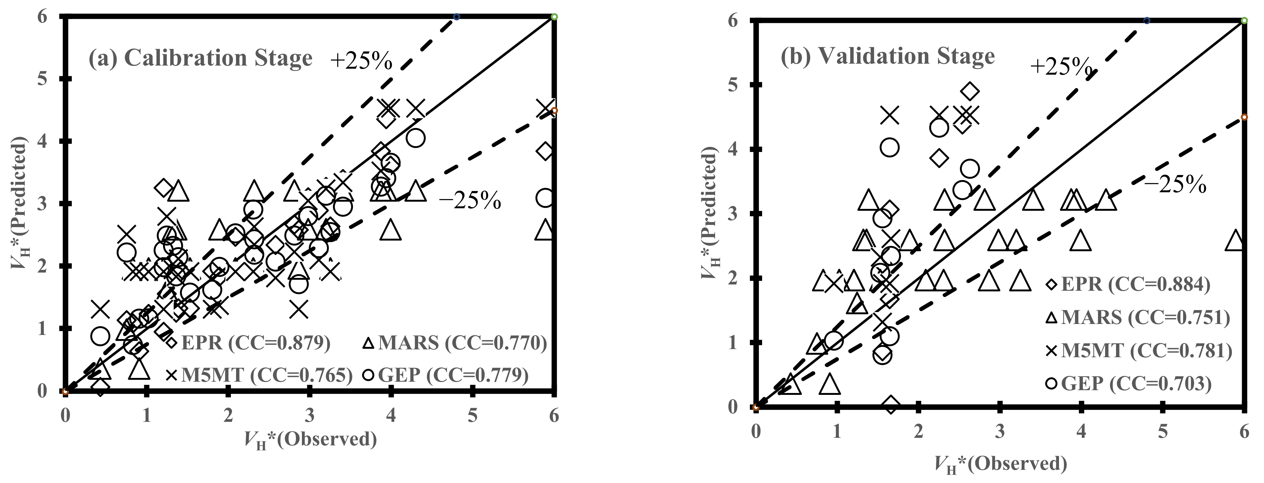
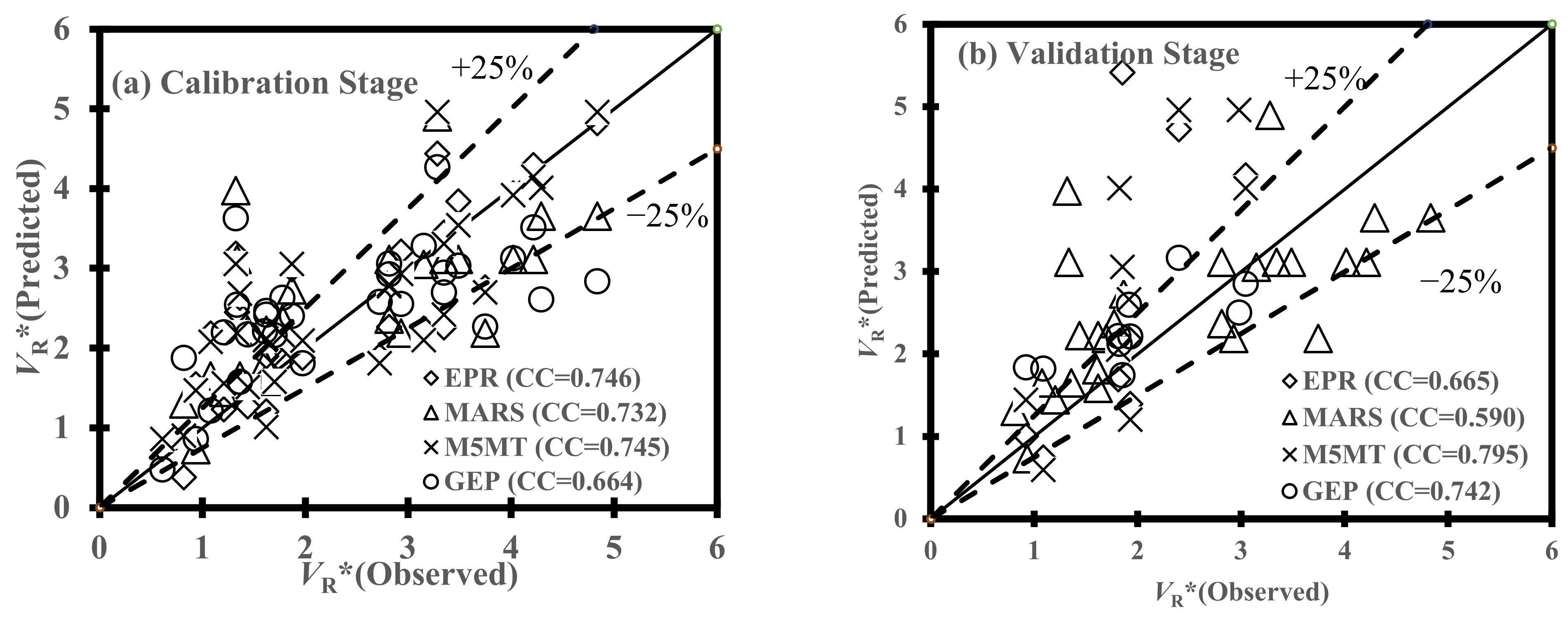
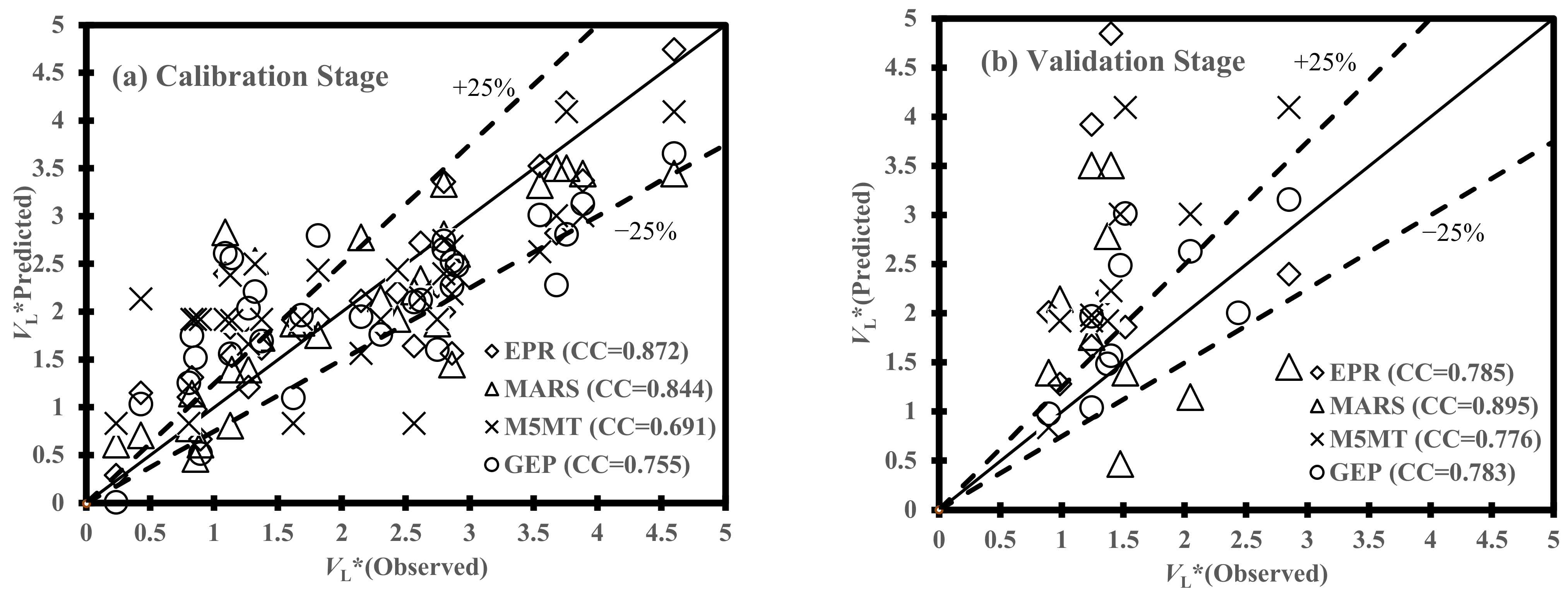
From the calibration and validation phases, the performance of AI models indicated a reasonable degree of efficiency for the estimation of the scour propagation rates. More specifically, statistical measures demonstrated that Equations (20) and (21) given by the GEP model had the best performance in the estimation of VR* and VH*, respectively, whereas the MARS model [Equation (25)] indicated the most accurate efficiency for the evaluation of VL*. On the other hand, the sixth combination of effective parameters (i.e., m θC,(1 − m)θW, 1 − e/D, KC) provided the best results for the scour propagation rates in the right and left hands of pipelines (VR* and VL*) when the GEP and MARS models fed, respectively. In the case of VH*, the MARS model fed by the fifth combination of dimensionless parameters (i.e., F, θC, θW,m,e/D) demonstrated the best performance. Generally, it was inferred that the performance of AI models stood at the highest level of accuracy when θC, θW, and m were not converted to one dimensionless parameter [C + (1 − m)θW].
-
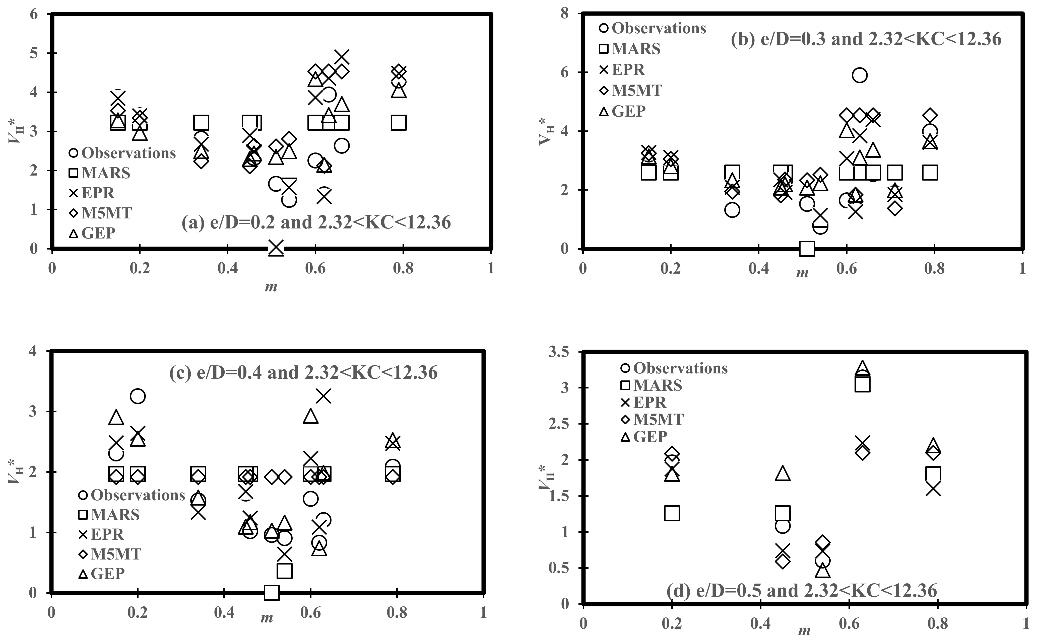
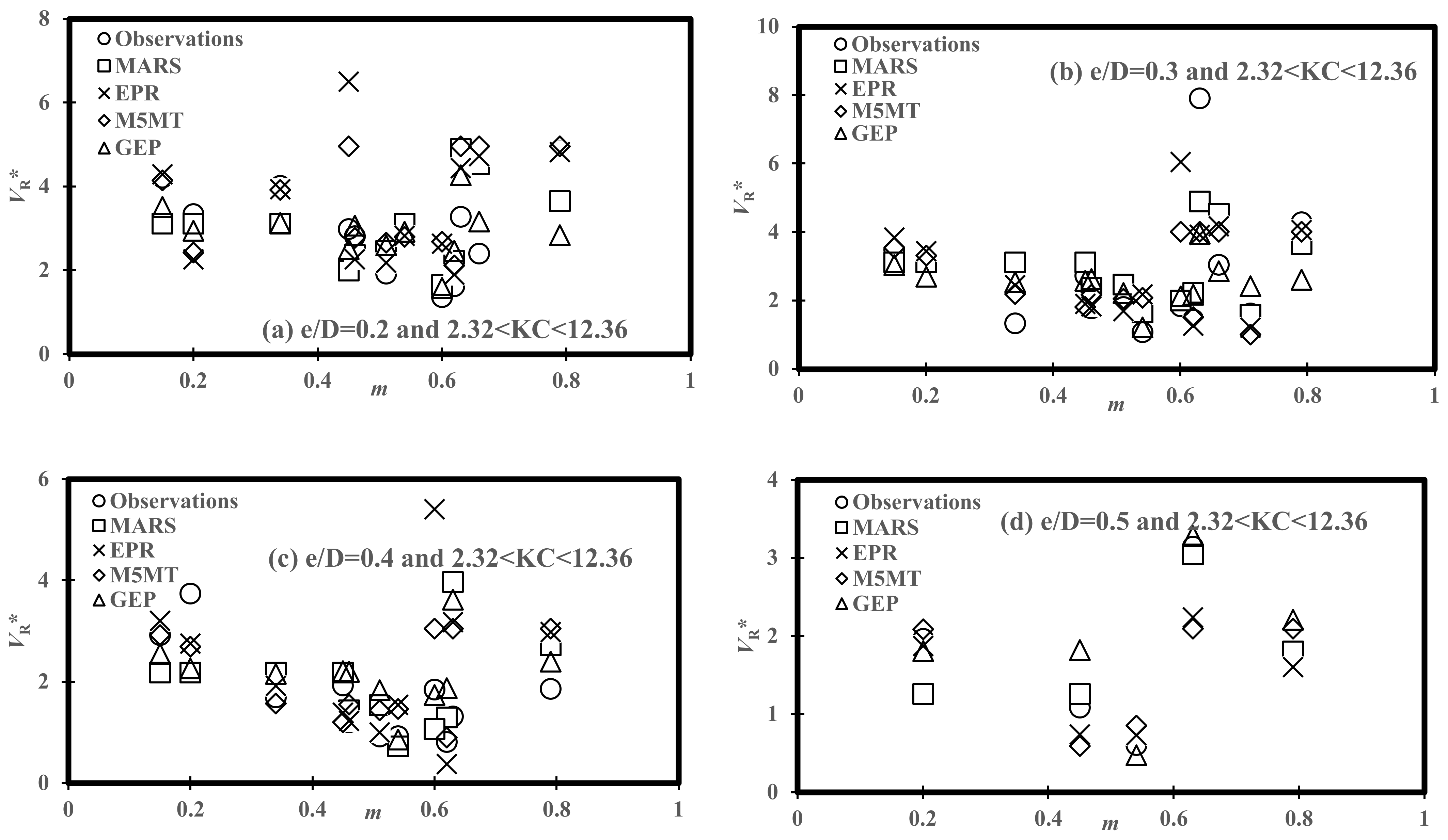
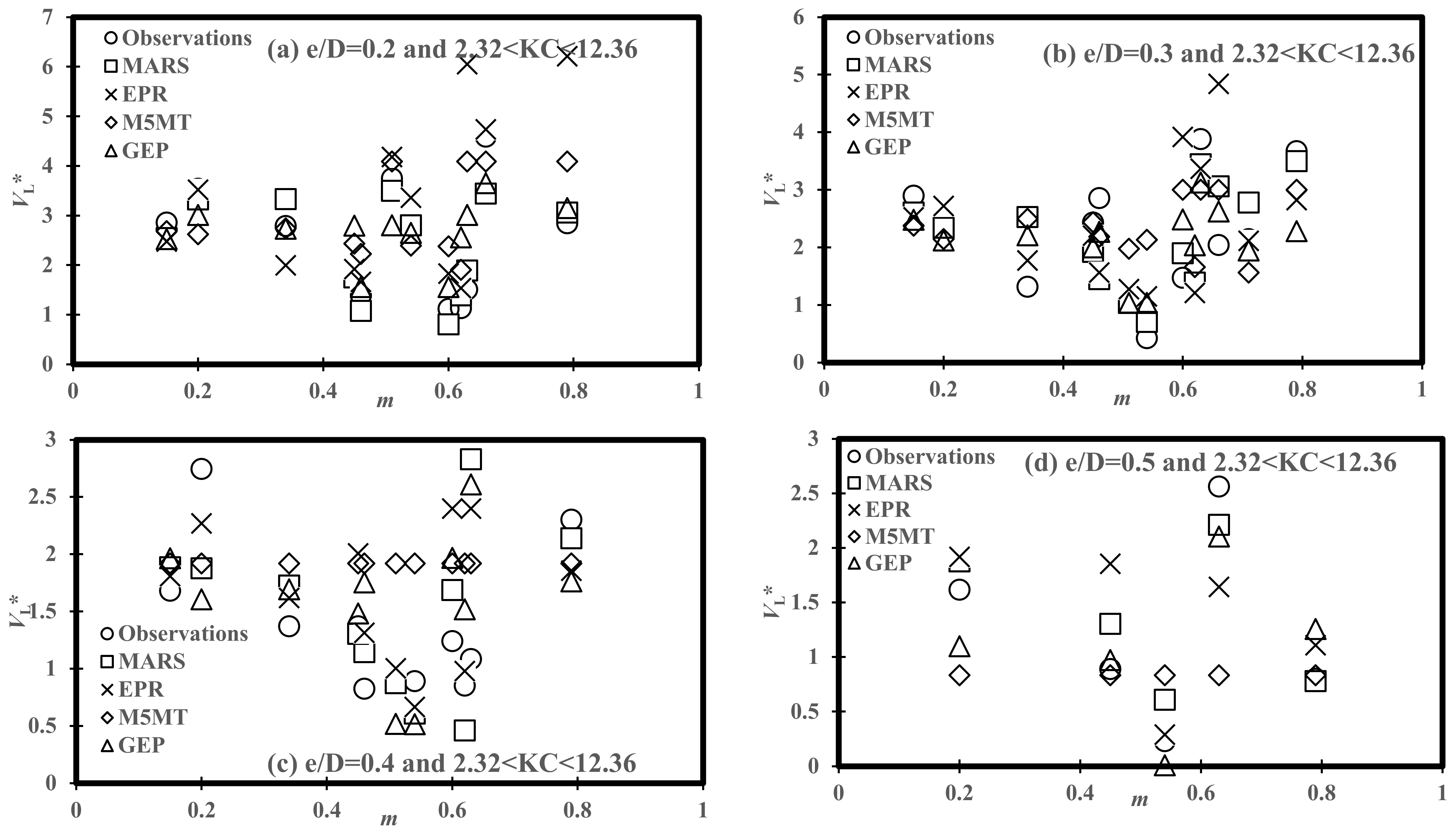
The physical consistency of the predictive models’ results has been studied by analyzing scour propagation rates versus the ratio of pipeline embedment depth and pipeline diameter (e/D), the ratio of current velocity to orbital velocity (m), and Keulegan–Carpenter number (KC). From variations of the scour propagation patterns versus m, it was found that scour propagation rates followed a decreasing trend for m = 0.2–0.6 and all ranges of e/D and KC, then; increased up to m = 0.8.
-
The effects of complexity level on the performance of AI models for 3D scour propagation rates was investigated. The EPR model was developed by Set 6 for the VH* prediction with complex expressions in comparison with M5MT and Equation (24) (MARS). Multivariate linear equations by M5MT were simpler than those obtained expressions by EPR and GEP models. Additionally, the EPR model provided VR* prediction with simpler mathematical structures than that developed by the GEP model [Equation (21)]. The sixth combination of input parameters has been applied to acquire a mathematical expression-based GEP model with three genes, indicating the lowest level of efficiency in the calibration stage in comparison with AI techniques. On the contrary, the MARS model with four dimensionless inputs (i.e., m θC,(1 − m)θW, 1 − e/D, KC) and the second-order polynomial had better performance in the calibration phase than linear equations by M5MT. Furthermore, explicit equations given by MARS and EPR models have lower complexity for the VL* estimation in comparison with the GEP model.

Author Contributions

Conceptualization, M.N., G.O. and F.S.-M.; methodology, M.N.; software, M.N.; validation, M.N. and G.O.; formal analysis, M.N. and G.O.; investigation, M.N. and G.O.; data curation, M.N. and G.O.; writing—original draft preparation, M.N., G.O. and F.S.-M.; writing—review and editing, M.N., G.O. and F.S.-M.; visualization, M.N., G.O. and F.S.-M.; supervision, M.N., G.O. and F.S.-M. All authors have read and agreed to the published version of the manuscript.

Funding

This research has been supported by Graduate University of Advanced Technology (Kerman-Iran) under grant number of 2594.

Institutional Review Board Statement

Not applicable.

Informed Consent Statement

Not applicable.

Data Availability Statement

Not applicable.

Acknowledgments

This research has been supported by the Graduate University of Advanced Technology (Kerman-Iran) under grant number 2594.

Conflicts of Interest

The authors declare no conflict of interest.

References

  1. Cheng, L.; Yeow, K.; Zang, Z.; Li, F. 3D scour below pipelines under waves and combined waves and currents. Coast. Eng. 2014, 83, 137–149. [Google Scholar] [CrossRef] [Green Version]
  2. Cheng, L.; Yeow, K.; Zhang, Z.; Teng, B. Three-dimensional scour below offshore pipelines in steady currents. Coast. Eng. 2009, 56, 577–590. [Google Scholar] [CrossRef]
  3. Adegboye, M.A.; Fung, W.-K.; Karnik, A. Recent Advances in Pipeline Monitoring and Oil Leakage Detection Technologies: Principles and Approaches. Sensors 2019, 19, 2548. [Google Scholar] [CrossRef] [PubMed] [Green Version]
  4. Sumer, B.M.; Fredsoe, J. The Mechanics of Scour in the Marine Environment; World Scientific: Singapore, 2002. [Google Scholar]
  5. Sumer, B.M.; FredsØe, J. Scour below pipelines in waves. J. Waterway Port Coast. Ocean Eng. 1990, 116, 307–323. [Google Scholar] [CrossRef]
  6. Sumer, B.M.; Truelsen, C.; Sichmann, T.; Fredsøe, J. Onset of scour below pipelines and self-burial. Coast. Eng. 2001, 42, 313–335. [Google Scholar] [CrossRef]
  7. Bernetti, R.; Bruschi, R.; Valentini, V.; Venturi, M. Pipelines placed on erodible seabeds. In Proceedings of the 9th International Conference on Offshore Mechanics and Artic Engineering, ASME, Houston, TX, USA, 18–23 February 1990; Volume 5, pp. 155–164. [Google Scholar]
  8. Lucassen, R.J. Scour Underneath Submarine Pipelines. In MAT Rep. PL-42A, Marine Tech. Res.; TU Delft: Delft, The Netherlands, 1984. [Google Scholar]
  9. Sumer, B.M.; Fredsøe, J. Scour around pipelines in combined waves and current. In Proceedings of the 15th Conference on Offshore Mechanics Arctic Engineering, Florence, Italy, 16–20 June 1996; American Society of Mechanical Engineers: New York, NY, USA, 1996; Volume 5, pp. 595–602. [Google Scholar]
  10. Fredsae, J.; Sumer, B.M.; Arnskov, M.M. Time scale for wave/current scour below pipelines. Int. J. Offshore Polar Eng. 1992, 2, 13–17. [Google Scholar]
  11. Wu, Y.; Chiew, Y.-M. Three-dimensional scour at submarine pipelines. J. Hydraul. Eng. 2012, 138, 788–795. [Google Scholar] [CrossRef]
  12. Wu, Y.; Chiew, Y.-M. Mechanics of three-dimensional pipeline scour in unidirectional steady current. J. Pipeline Syst. Eng. 2013, 4, 3–10. [Google Scholar] [CrossRef]
  13. Najafzadeh, M.; Saberi-Movahed, F. GMDH-GEP to predict free span expansion rates below pipelines under waves. Mar. Georesources Geotechnol. 2019, 37, 375–392. [Google Scholar] [CrossRef]
  14. Ehteram, M.; Ahmed, A.N.; Ling, L.; Fai, C.M.; Latif, S.D.; Afan, H.A.; Banadkooki, F.B.; El Shafie, A. Pipeline scour rates prediction-based model utilizing a Multilayer Perceptron-Colliding Body algorithm. Water 2020, 12, 902. [Google Scholar] [CrossRef] [Green Version]
  15. Najafzadeh, M.; Oliveto, G. Exploring 3D wave-induced scouring patterns around subsea pipelines with Artificial Intelligence techniques. Appl. Sci. 2021, 11, 3792. [Google Scholar] [CrossRef]
  16. Najafzadeh, M.; Oliveto, G. Scour Propagation Rates around Offshore Pipelines Exposed to Currents by Applying Data-Driven Models. Water 2022, 14, 493. [Google Scholar] [CrossRef]
  17. Hansen, E.A.; Staub, C.; Fredsøe, J.; Sumer, B.M. Time-development of scour induced free spans of pipelines. In Proceedings of the 10th Conference on Offshore Mechanics and Arctic Engineering (OMAE), Stavanger, Norway, 23–28 June 1991. [Google Scholar]
  18. Soulsby, R. Dynamics of Marine Sands: A Manual for Practical Applications; Thomas Telford: London, UK, 1997. [Google Scholar]
  19. Ferreira, C. Gene expression programming: A new adaptive algorithm for solving problems. Complex Syst. 2001, 13, 87–129. [Google Scholar]
  20. Ferreira, C. Gene Expression Programming, 2nd ed.; Springer: Berlin/Heidelberg, Germany, 2006. [Google Scholar]
  21. Friedman, J.H. Multivariate adaptive regression splines. Ann. Statist. 1991, 19, 1–67. [Google Scholar] [CrossRef]
  22. Mokhtia, M.; Eftekhari, M.; Saberi-Movahed, F. Feature selection based on regularization of sparsity based regression models by hesitant fuzzy correlation. Appl. Soft Comput. 2020, 91, 106255. [Google Scholar] [CrossRef]
  23. Mokhtia, M.; Eftekhari, M.; Saberi-Movahed, F. Dual-manifold regularized regression models for feature selection based on hesitant fuzzy correlation. Knowl.-Based Syst. 2021, 229, 107308. [Google Scholar] [CrossRef]
  24. Quinlan, J.R. Learning with Continuous Classes. In Proceedings of the 5th Australian Joint Conference on Artificial Intelligence (AI ’92); World Scientific: Singapore, 1992; pp. 343–348. [Google Scholar]
  25. Granata, F.; de Marinis, G. Machine learning methods for wastewater hydraulics. Flow Meas. Instrum. 2017, 57, 1–9. [Google Scholar] [CrossRef]
  26. Granata, F.; Saroli, M.; de Marinis, G.; Gargano, R. Machine learning models for spring discharge forecasting. Geofluids 2018, 2018, 8328167. [Google Scholar] [CrossRef] [Green Version]
  27. Solomatine, D.P.; Xue, Y. M5 Model Trees and Neural Networks: Application to Flood Forecasting in the Upper Reach of the Huai River in China. J. Hydrol. Eng. 2004, 9, 491–501. [Google Scholar] [CrossRef]
  28. Di Nunno, F.; Alves Pereira, F.; de Marinis, G.; Di Felice, F.; Gargano, R.; Miozzi, M.; Granata, F. Deformation of Air Bubbles Near a Plunging Jet Using a Machine Learning Approach. Appl. Sci. 2020, 10, 3879. [Google Scholar] [CrossRef]
  29. Granata, F.; Di Nunno, F. Air Entrainment in Drop Shafts: A Novel Approach Based on Machine Learning Algorithms and Hybrid Models. Fluids 2022, 7, 20. [Google Scholar] [CrossRef]
  30. Etemad-Shahidi, A.; Yasa, R.; Kazeminezhad, M.H. Prediction of wave-induced scour depth under submarine pipelines using machine learning approach. Appl. Ocean Res. 2011, 33, 54–59. [Google Scholar] [CrossRef] [Green Version]
  31. Giustolisi, O.; Doglioni, A.; Savic, D.A.; Webb, B.W. A multi-model approach to analysis of environmental analysis. Environ. Modell. Softw. 2007, 22, 674–682. [Google Scholar] [CrossRef] [Green Version]
  32. Giustolisi, O.; Savic, D.A. Advances in data-driven analyses and modelling using EPR-MOGA. J. Hydroinf. 2009, 11, 225–236. [Google Scholar] [CrossRef]
  33. Laucelli, D.; Giustolisi, O. Scour depth modeling by a multi-objective evolutionary paradigm. Environ. Model. Softw. 2011, 26, 498–509. [Google Scholar] [CrossRef]
  34. Savic, D.A.; Giustolisi, O.; Berardi, L.; Shepherd, W.; Djordjevic, S.; Saul, A. Modelling sewer failure by evolutionary computing. Water Manag. 2006, 159, 111–118. [Google Scholar] [CrossRef]
  35. Berardi, L.; Giustolisi, O.; Kapelan, Z.; Savic, D.A. Development of pipe deterioration models for water distribution systems using EPR. J. Hydroinf. 2008, 10, 113–126. [Google Scholar] [CrossRef] [Green Version]
Figure 1. Illustrative sketch of 3D scour hole pattern with free span development at an underwater pipeline under orbital and current velocity profiles.
Water 14 01589 g001
Figure 2. Distribution patterns for the effective parameters regarded in this research: (a) ratio of the pipeline embedded depth to pipeline diameter, e/D; (b) Keulegan−Carpenter number, KC; (c) ratio of the maximum undisturbed orbital rate at the sea bottom just above the boundary of the waves to the flow velocity due to currents, m; (d) Shields’ parameter due to waves, θW; (e) Shields’ parameter due to currents, θC; (f) dimensionless scouring propagation rate around offshore pipeline at the longitudinal direction, VH*; (g) dimensionless scouring propagation rate around offshore pipeline at the right-hand shoulder of the pipeline, VR*; (h) dimensionless scouring propagation rate around offshore pipeline at the left-hand shoulder of the pipeline, VL*.
Water 14 01589 g002aWater 14 01589 g002b
Figure 3. Performance of soft computing models in the prediction of VH* for (a) calibration and (b) validation stages.
Water 14 01589 g003
Figure 4. Performance of soft computing models in the prediction of VR* for (a) calibration and (b) validation stages.
Water 14 01589 g004
Figure 5. Performance of soft computing models in the prediction of VL* for (a) calibration and (b) validation stages.
Water 14 01589 g005
Figure 6. Comparisons of the soft computing models’ performance for variation of VH* versus m in for various levels of e/D: (a) e/D = 0.2, (b) e/D = 0.3, (c) e/D = 0.4, and (d) e/D = 0.5.
Water 14 01589 g006
Figure 7. Comparisons of the soft computing models’ performance for variation of VR* versus m in for various levels of e/D: (a) e/D = 0.2, (b) e/D = 0.3, (c) e/D = 0.4, and (d) e/D = 0.5.
Water 14 01589 g007
Figure 8. Comparisons of the soft computing models’ performance for variation of VL* versus m in for various levels of e/D: (a) e/D = 0.2, (b) e/D = 0.3, (c) e/D = 0.4, and (d) e/D = 0.5.
Water 14 01589 g008
Table 1. Optimal selection of input variables.
Set No.List of Input Variables
Set 1e/D,KC,m,θW,θC
Set 21 − e/D,KC, (1 − m)θW + mθC
Set 31 − e/D,F, θW, θC
Set 41 − e/D, F, (1 − m)θW + C
Set 5e/D, F,m,θW,θC
Set 61 − e/D,KC, (1 − m)θW,C
Set 71 − e/D,KC, [(1 − m)θW + C]5/3
Table 2. Statistical descriptions of variables.
ParametersData RangeAverageStandard DeviationCoefficient of Variation
T (s)1–21.5360.4190.273
UW (m/s)0.11–0.340.2610.0740.284
E (cm)0.5–2.51.570.5860.3717
u* (m/s)0.0036–0.02820.01710.007690.449
UC (m/s)0.06–0.470.2910.1300.445
VH (mm/s)0.33–4.551.6690.8930.535
m0.15–0.790.5050.1870.371
θW0.0278–0.13150.080570.030940.361
θC0.00048–0.02970.013560.009080.669
KC2.2–13.68.3143.7230.448
e/D0.2–0.50.3190.1020.319
VH*0.26–3.611.3260.7090.535
VR*0.609–7.90232.4111.3711.634
VL*0.233–4.591.9521.0360.6023
Table 3. Correlations of GEP performance in the calibration and validation stage for 3D scour rates.
Set No.VH*VR*VL*
CalibrationValidationCalibrationValidationCalibrationValidation
10.59210.7480.64820.83450.61150.4135
20.67390.50560.51750.57680.56920.6290
30.74810.61180.61600.79130.50900.6619
40.61510.89330.593590.84380.65870.7778
50.77960.70290.67550.62510.78230.7071
60.71850.84770.66450.74250.736170.6746
70.46070.48670.460550.69110.75520.7833
Table 4. Setting parameters of GEP performance in the calibration phases for 3D scour rates prediction.
ParametersDescription of ParametersSetting of Parameters
P1Function set+, −, ×, /, Power (x2), (1 − x), 1/x, Average (x1,x2), Atan (x), 3Rt, Ln, Min
P2Linking functionAddition
P3Mutation rate0.00138
P4Inversion rate0.00546
P5One-point and two-point recombination rates0.00277
P6Gene recombination rate 0.00277
P7Permutation0.00546
P8Maximum tree depthVH* (6), VR* (5), VL* (4)
P9Number of gene3
P10Number of chromosomes30
P11Number of generationVH* (1364), VR* (861), VL* (3916)
P12Best fitness valueVH* (557.26), VR* (466.89), VL* (578.77)
Table 5. Correlations of MARS performance in the calibration and validation stages for 3D scour rates.
Set No.VH*VR*VL*
CalibrationValidationCalibrationValidationCalibrationValidation
10.8370.5580.81130.47770.63610.44
20.77050.7513NanNanNanNan
30.83700.55860.39450.59650.61440.4405
40.61420.56220.39450.59650.77440.4408
50.79430.41480.73920.22630.68350.5542
60.75780.69550.73250.59030.84390.8949
70.43960.64380.84750.36380.63170.7374
Table 6. Coefficients and basis functions for MARS models in scour depth prediction.
Basis Functions Used in the Prediction of VH*
BF1max(0, 0.61751 − F)
BF2max(0, 0.11276 − (1 − m)θWC)
BF3max(0, 0.73254 − (1 − e/D))
BF4max(0, 0.7 − (1 − e/D)) × max(0, F − 0.30369)
Basis functions used in the prediction of VR*
BF1max(0, C − 0.03862)
BF2max(0, C − 0.064886)
BF3max(0, 0.064886 − C)
BF4max(0, 6.3 − KC)
BF5max(0, 0.7 − (1 − e/D)) × max(0, 0.078754 − ((1 − m)θW))
BF6 max(0, (1 − e/D) − 0.6) × max(0, (1 − m)θW − 0.068215 )
Basis functions used in the prediction of VL*
BF1max(0, C − 0.03044)
BF2max(0, 0.7 − (1 − e/D))
BF3max(0, 0.0478720 − (1 − m)θW)
BF4max(0, (1 − m)θW − 0.0478720)×max(0, C − 0.017761)
Table 7. Correlations of M5MT performance in the calibration and validation stage for 3D scour rates.
Set No.VH*VR*VL*
CalibrationValidationCalibrationValidationCalibrationValidation
10.650.750.3610.6810.48660.6394
20.4340.59620.3610.6800.48660.6394
30.7560.7750.3610.6800.4860.639
40.44090.59600.78870.6700.48660.6394
50.7650.7810.7450.79560.67940.7740
60.7530.7740.7230.8200.69160.7760
70.43390.5960.3610.6810.49440.6440
Table 8. Lists of M5MT details in VH* estimates.
Rules of M5MT#1 with Focusing on Pruning and Smoothing Phases
Rule: 1
IF
e/D < = 0.35
θC < = 0.087
THEN  VH* = −5.6911 × θW + 27.9909 × θC − 6.8389 × m−2.8633 × e/D + 6.0401
Rule: 2
IF
e/D > 0.35
THEN  VH* = −6.015 × e/D + 4.3233
Rule: 3
VH* = +4.5309
Table 9. Lists of M5MT details in VR* estimates.
Rules of M5MT#1 with Focusing on Pruning and Smoothing Phases
Rule: 1
IF
θC < = 0.087
THEN  VR*= −4.3517 × θW + 17.5692 × θC − 6.868 × m − 6.0857 × e/D + 7.0983
THEN  VR*= −9.5347 × e/D + 6.8673
Table 10. Lists of M5MT details in VL* estimates.
Rules of M5MT#1 with Focusing on Pruning and Smoothing Phases
Rule: 1
IF
     1 − e/D > 0.65
     C < = 0.052
THEN  VL* = 2.4945 × (1 − e/D) + 8.6366 × (1 − m)θW + 8.5379 × C − 0.6196
Rule: 2
VL*= −10.8666 × (1 − e/D) − 4.5984
Table 11. Correlations of EPR performance in the calibration and validation stages for 3D scour rates.
Set No.VH*VR*VL*
CalibrationValidationCalibrationValidationCalibrationValidation
10.77800.41370.74130.68000.791730.2661
20.65120.88810.58980.81940.67710.7373
30.68870.60180.72190.64670.87880.3685
40.63820.72970.53230.83960.69210.7264
50.68870.60310.74580.66510.87250.7853
60.87940.88420.74320.65560.73780.6403
70.62580.57690.58000.82850.69560.6735
Table 12. The best statistical performances of the soft computing models for prediction of VH*.
Soft Computing ModelsCalibration Stage
CCRMSEMAPESIDR
MARS (Developed by Set 2)0.7700.9870.3980.4241.167
EPR (Developed by Set 6)0.8790.5950.2240.2561.046
M5MT (Developed by Set 5)0.7650.8170.4740.3481.286
GEP (Developed by Set 5)0.7790.8010.3480.3441.183
Soft Computing ModelsValidation Stage
CCRMSEMAPESIDR
MARS (Developed by Set 2)0.7510.9290.4980.5160.897
EPR (Developed by Set 6)0.8841.5090.7960.8320.927
M5MT (Developed by Set 5)0.7811.5430.6920.5291.661
GEP (Developed by Set 5)0.7031.2390.5650.5381.403
Table 13. The best statistical performances of the soft computing models for prediction of VR*.
Soft Computing ModelsCalibration Stage
CCRMSEMAPESIDR
MARS (Developed by Set 6)0.7321.0410.3880.4081.111
EPR (Developed by Set 5)0.7461.0030.3080.3931.120
M5MT (Developed by Set 5)0.7451.0060.3120.3941.163
GEP (Developed by Set 6)0.6641.1420.3730.4471.174
Soft Computing ModelsValidation Stage
CCRMSEMAPESIDR
MARS (Developed by Set 6)0.5900.9810.3840.4461.632
EPR (Developed by Set 5)0.6652.2360.7640.8781.234
M5MT (Developed by Set 5)0.7951.3880.5810.5271.415
GEP (Developed by Set 6)0.7421.1420.3150.2231.259
Table 14. The best statistical performances of the soft computing models for prediction of VL*.
Soft Computing ModelsCalibration Stage
CCRMSEMAPESIDR
MARS (Developed by Set 6)0.8440.6020.3140.2861.108
EPR (Developed by Set 5)0.8720.5440.2900.2591.129
M5MT (Developed by Set 6)0.6910.8070.5980.3831.374
GEP (Developed by Set 7)0.7550.7390.4470.3521.144
Soft Computing ModelsValidation Stage
CCRMSEMAPESIDR
MARS (Developed by Set 6)0.8950.4400.2480.2531.139
EPR (Developed by Set 5)0.7852.2030.9910.9911.991
M5MT (Developed by Set 6)0.7761.1970.6790.4391.666
GEP (Developed by Set 7)0.7830.6740.3580.3691.231
Table 15. RMSE values for performance of the soft computing models for variation of velocity ratio.
Soft Computing ModelsVariation of VH* vs. m for 2.32 < KC < 12.36
e/D = 0.2e/D = 0.3e/D = 0.4e/D = 0.5
MARS0.9431.2510.6960.563
EPR0.9471.0380.8120.390
M5MT1.1051.2290.7410.835
GEP0.9021.1870.4260.803
Soft Computing ModelsVariation of VR* vs. m for 2.32 < KC < 12.36
e/D = 0.2e/D = 0.3e/D = 0.4e/D = 0.5
MARS1.0291.1411.0610.495
EPR1.3661.7211.3260.439
M5MT1.1821.3610.8620.577
GEP0.8421.3231.0080.439
Soft Computing ModelsVariation of VL* vs. m for 2.32 < KC < 12.36
e/D = 0.2e/D = 0.3e/D = 0.4e/D = 0.5
MARS0.4370.6710.6420.318
EPR1.6851.1570.6230.626
M5MT1.0350.9100.7920.891
GEP0.8050.7160.7560.386
Publisher’s Note: MDPI stays neutral with regard to jurisdictional claims in published maps and institutional affiliations.

