
Unfavorable Geology and Mitigation Measures for Water Inrush Hazard during Subsea Tunnel Construction: A Global Review

 ,
,
Abstract
:1. Introduction
2. Materials and Methods
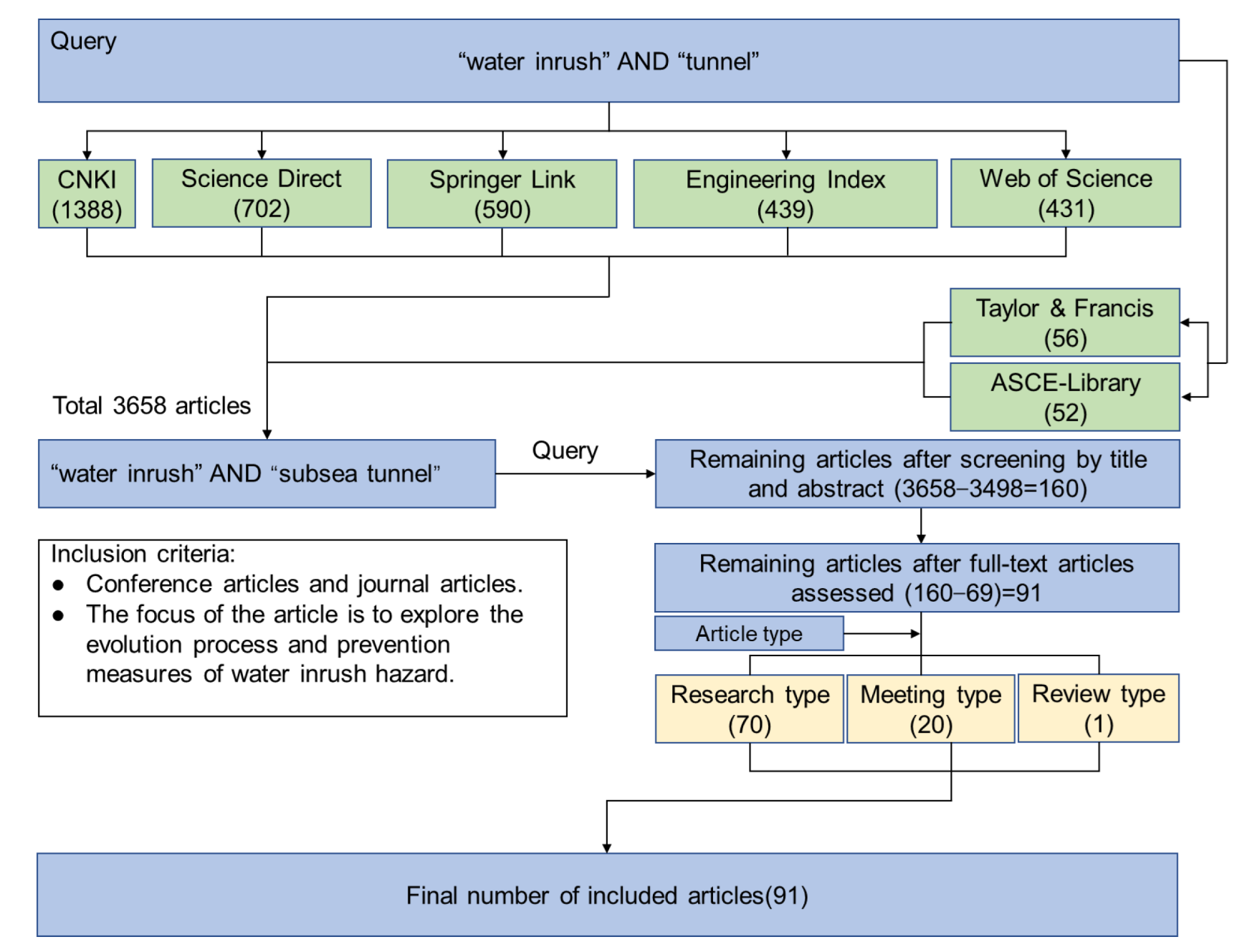
2.1. Literature Retrieval
2.2. Search Results Analysis
3. Causes of Water Inrush in Subsea Tunnels
3.1. Unfavorable Geological
- (1)
- FaultTunnel geological exploration is difficult, and the investment is large. When water inrush occurs, a fault with cracks is the preferred natural plane for water inrush. Nilsen [37,38] pointed out that a fault was the most unstable factor by analyzing water inrush problems in the construction of the Ellingsøy and Vardø Tunnels in Norway. After water inrush of the Old Dana Tunnel in Japan, an investigation of the geological conditions of the accident revealed that the presence of a fault fracture zone led to its destabilization and damage under high water pressure, resulted in serious consequences. Relevant studies show [39,40] that the strike, dip angle, width of fault fracture zone, the degree of rock fracture, the activity of groundwater and the spatial relationship with the tunnel can have important impacts on the stability of the tunnel.
- (2)
- Jointed or fractured rockMost water inrush is accompanied by surrounding rock conditions with jointed fissures. Under the influence of engineering disturbance, surrounding rock stress is concentrated, and the existing jointed fissures begin to expand. In this process, the mechanical parameters of rock damage are reduced due to deterioration, and the adjacent joint fissures expand and connect with each other. For example, stress concentration made the existing cracks in the Slemmestad and Vollsfjord Tunnels in Norway [41,42] develop and connect with seawater. and high pressure caused the cracks to penetrate and form water-conducting passages [43,44,45,46,47]. During the construction of the Qingdao Jiaozhou Bay Tunnel in China [48], the back of the initial support fell off, and water was hydraulically split along existing fissures to form a water channel.
- (3)
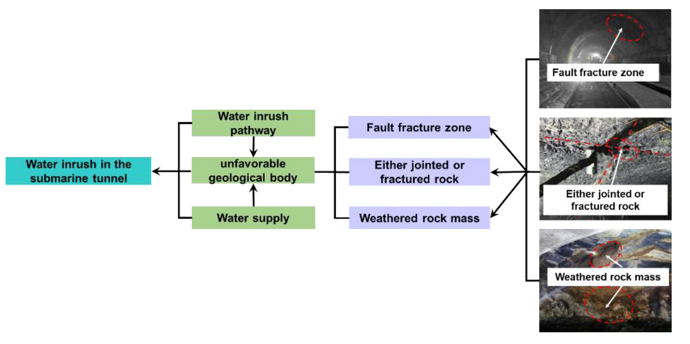
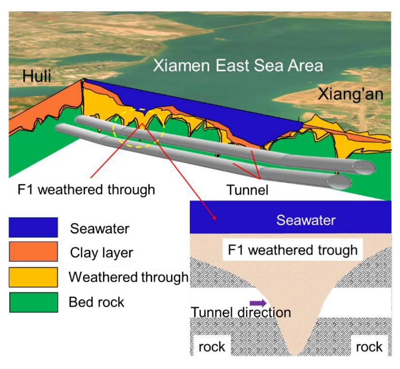
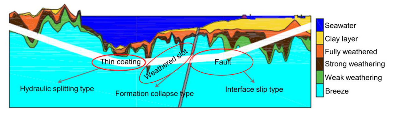
- Weathered rockTypical weathered rock is easily softened when it meets water [49]. When a tunnel passes through this kind of rock mass, due to its poor stability, formation collapse occurs and induces water inrush. The most representative weathered rock is an undersea weathered trough, which is prone to water inrush due to direct communication between fissures and seawater (Figure 5). For example, in October 2006, a large-scale water inrush occurred when the Xiang’an Tunnel [19] crossed the F1 weathered trough, and disintegration of surrounding rock in water reached 80%.
3.2. Water Supply
3.3. Water Inrush Channel
4. Water Inrush Modes
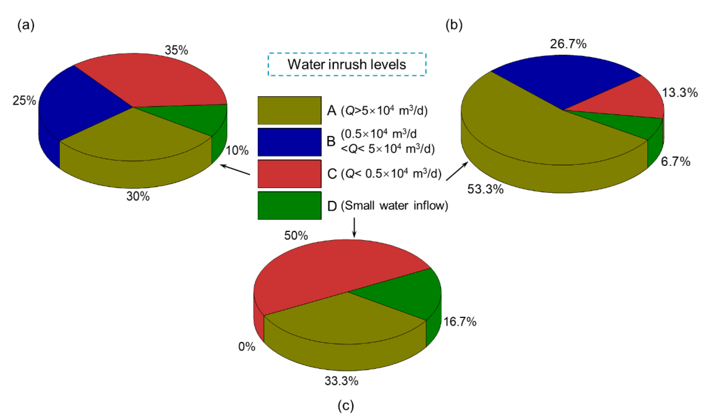
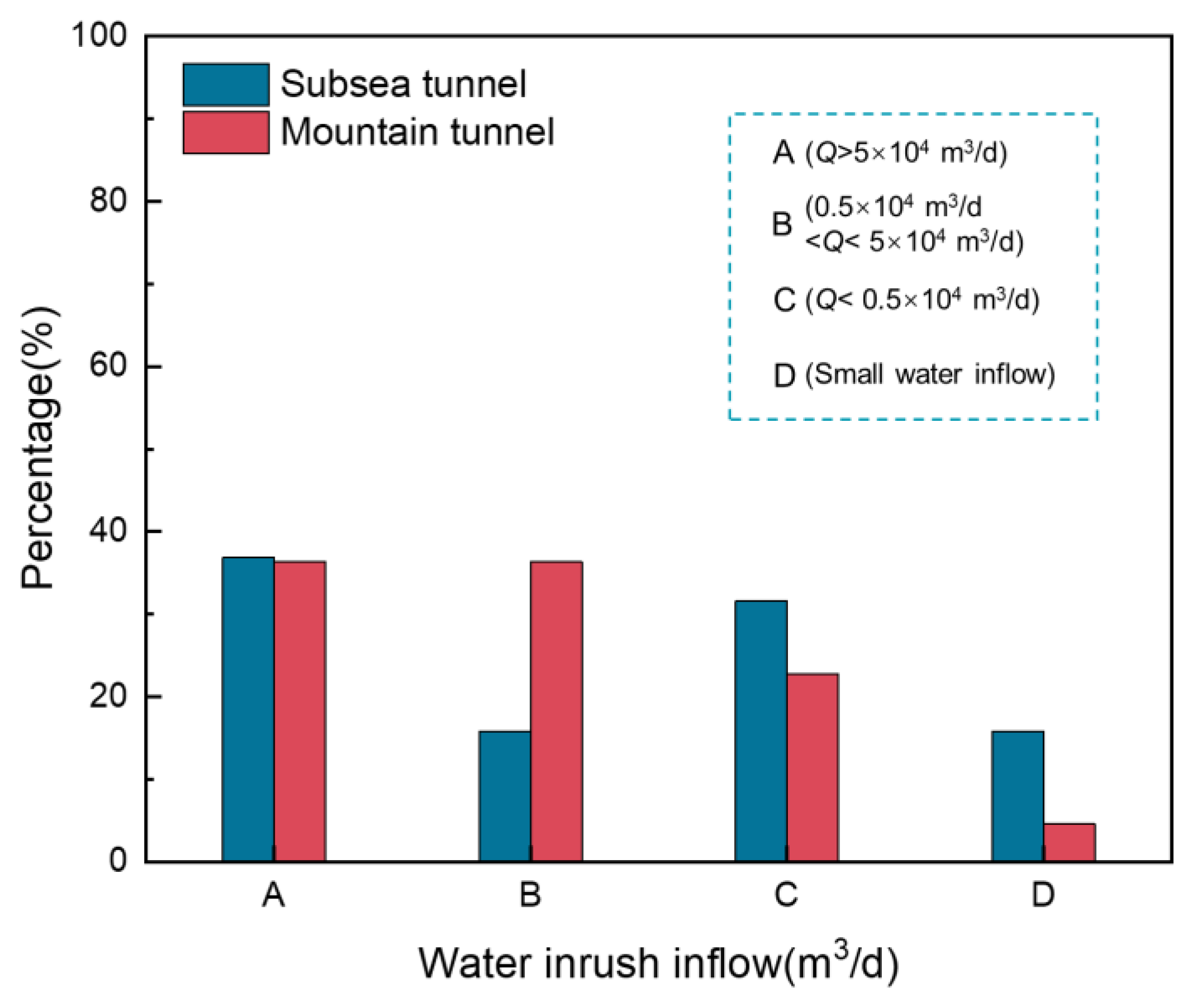
4.1. Statistical Investigation of Tunnel Water Inrush Accidents
4.2. Analysis of Water Inrush Characteristics
4.3. Water Inrush Modes
4.3.1. Hydraulic Fracturing Type
4.3.2. Formation Collapse Type
4.3.3. Interface Slip Type
5. Prevention and Treatment of Water Inrush Hazards Induced by Unfavorable Geology
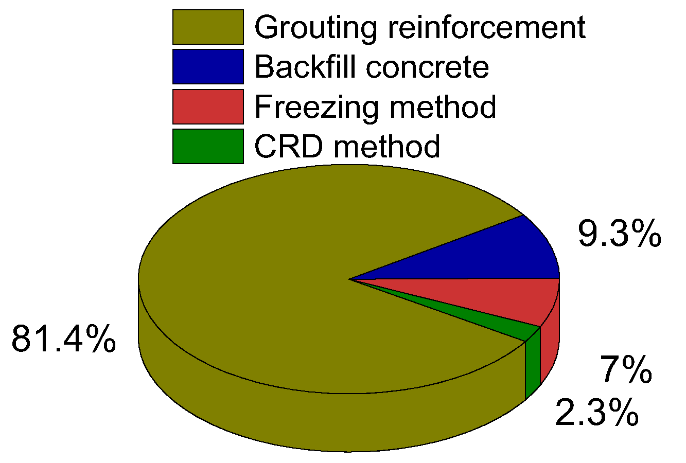
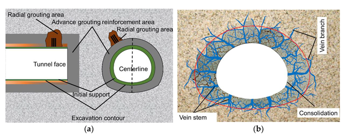
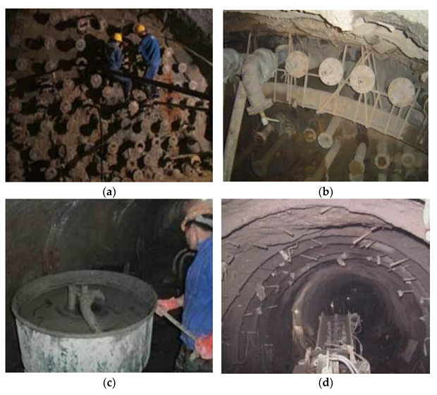
5.1. Formation Reinforcement
- (1)
- Grouting reinforcement
- (2)
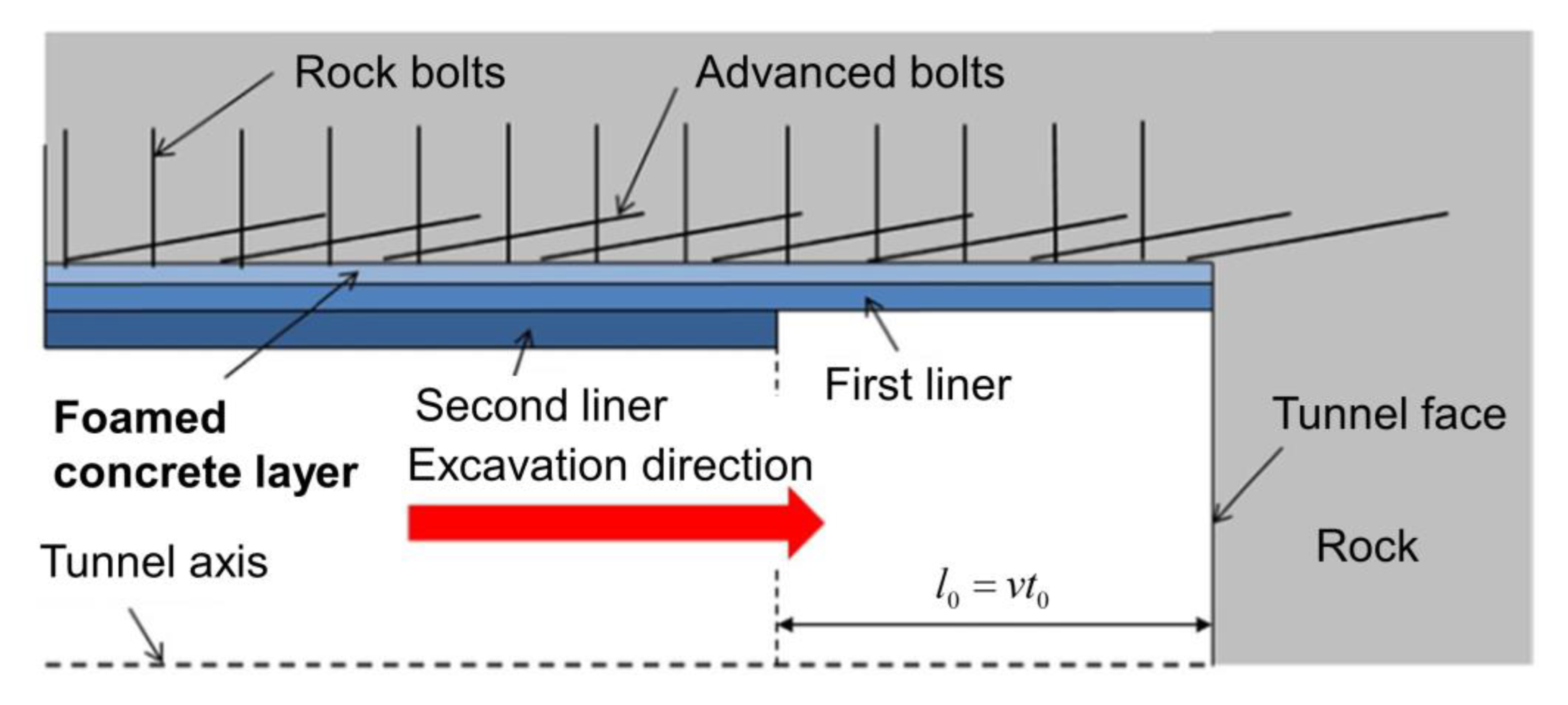
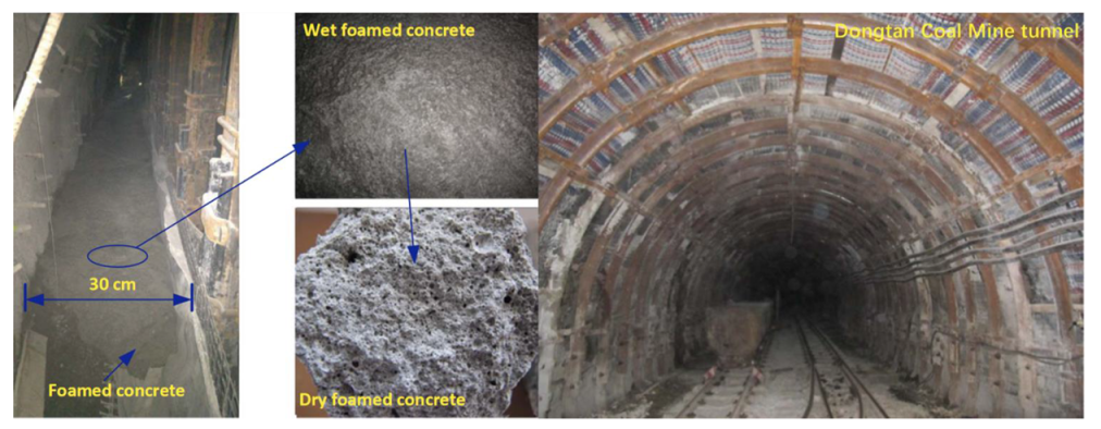
- Backfilled concrete
- (3)
- Artificial freezing method
5.2. Optimization of Construction Method
5.3. Advanced Geological Prediction and Field Monitoring Technology
- (1)
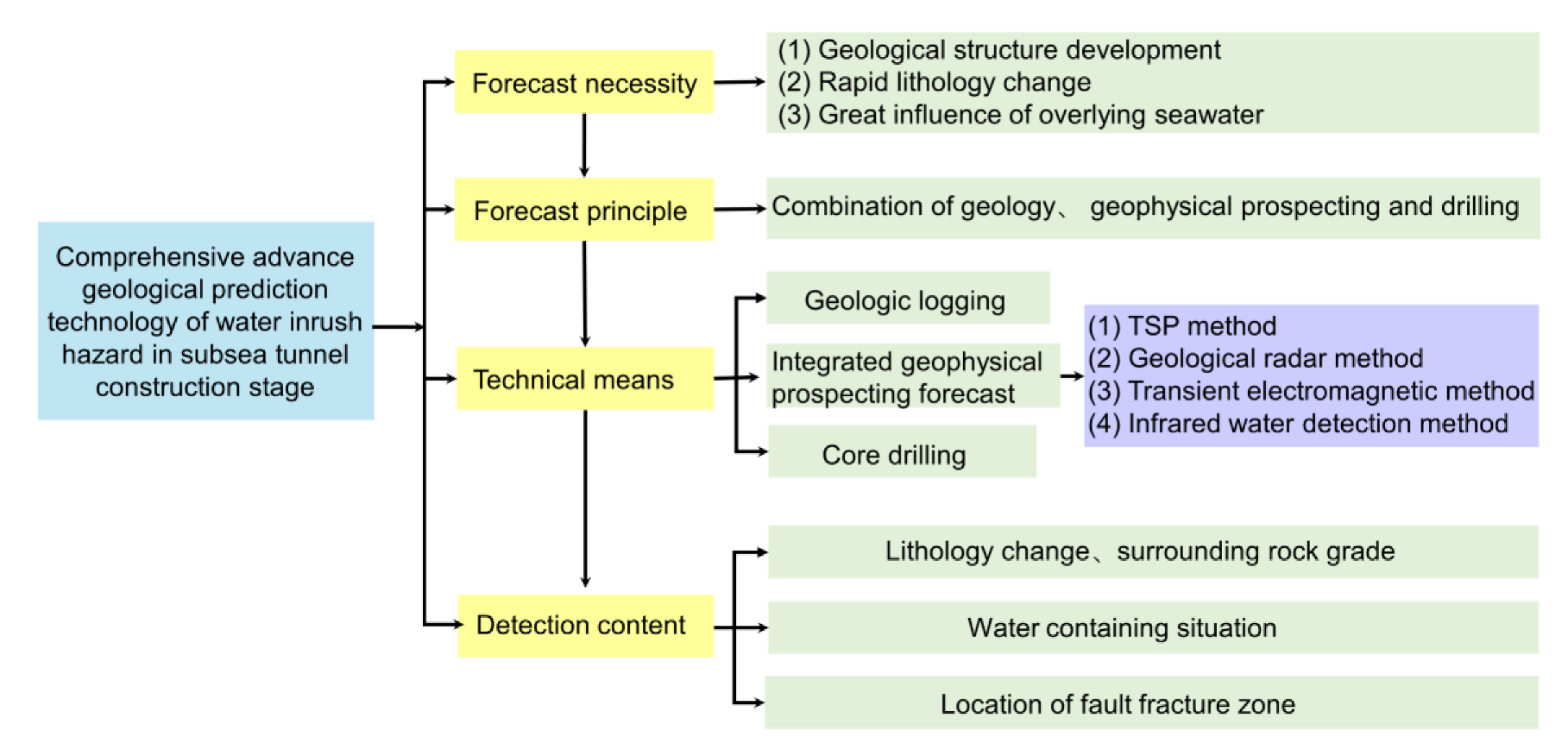
- Advanced geological prediction
- (2)
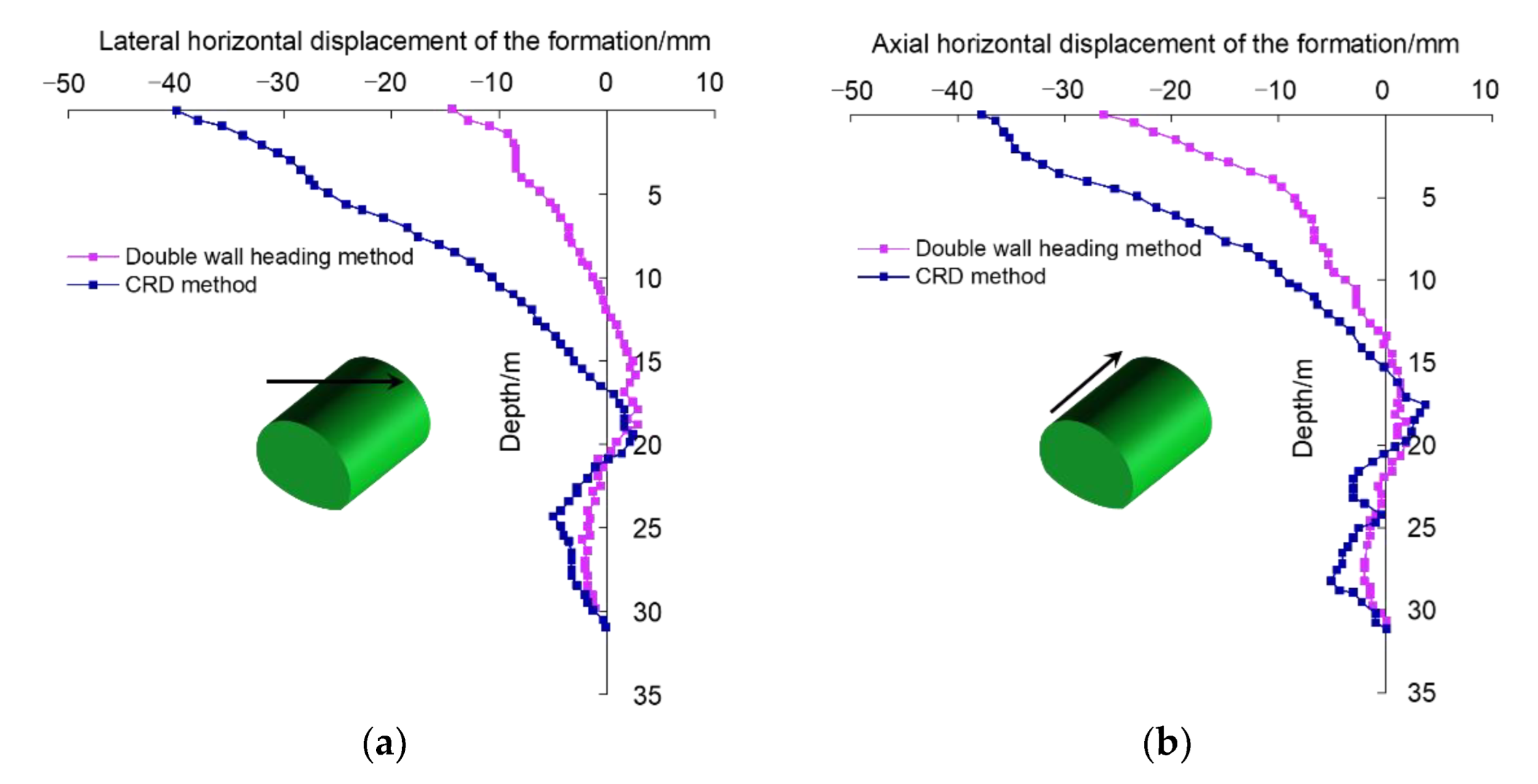
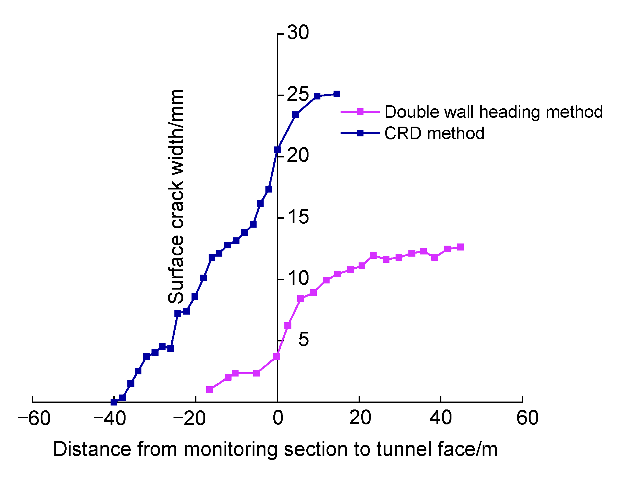
- Formation deformation control method
- (3)
- Micro-Seismic Monitoring Method
6. Discussion
6.1. Difficulties in Subsea Tunnel Construction
- (1)
- Much of the project area is covered by water and, in most cases, there is a considerable soil cover on the sea floor. Special investigation techniques are required, and interpretation of the results is more uncertain than for most on-shore tunnel projects.
- (2)
- The potential of water inflow is unknown, and the hydraulic pressure is often very high. In addition, all leakage water has to be pumped out of the descending tunnel.
- (3)
- The locations of fjords and straits are, in most cases, defined by major faults or weakness zones in the bedrock. Even in good quality rock masses, the deepest part of the fjord, and thus the most critical part of the tunnel, often coincides with significant weakness zones representing very difficult ground conditions.
6.2. Comparison of Three Water Inrush Modes
- (1)
- For hydraulic fracturing, the cracks are filled with seawater immediately after they are formed. Under the action of hydraulic pressure, they expand and generate new branch cracks, causing adjacent cracks to connect and further connect the high-pressure water-rich zone and the tunnel front surface. The direction of the crack surface in the layer is analyzed for the position where hydraulic splitting may occur, and the corresponding weak position can be grouted for reinforcement without large-scale grouting.
- (2)
- For formation collapse, the stratum conditions are generally poor, and the water damage caused is sudden and extremely harmful. Generally speaking, the following aspects should be considered for reinforcement. ➀ Curtain grouting or artificial freezing for preliminary reinforcement to avoid large-scale water inrush from collapse of the surrounding rock. ➁ Further improvement of the reinforcement effect of curtain grouting; ➂ Backfill grouting behind the initial support and performing radial grouting in poor geological sections.
- (3)
- For interface slip, when the surrounding rock conditions on both sides of the discontinuous structural plane or fracture zone are good, the overall instability of the tunnel will not be caused by structural plane sliding. Grouting reinforcement can only be carried out for discontinuous structural planes or fracture zone areas. If the surrounding rock conditions on both sides of the discontinuous structural plane or the fracture zone are poor and may further cause stratum collapse, curtain grouting should be used for reinforcement.
7. Summary, Conclusions and Recommendations for Future Research
7.1. Summary and Conclusions
7.2. Recommendations for Future Research
- (1)
- In practical engineering, external factors such as earthquake, blasting, ground stress, and construction disturbance have an important influence on the occurrence of mud inrush disasters. However, the impact of external factors on the occurrence of adverse geological structures and mud inrush disasters is still unclear. Therefore, there is an urgent need to carry out research on the mechanism of mud inrush disasters and the criteria for disaster prevention, focusing on the multi-field coupling effects of water-earthquake-construction disturbance.
- (2)
- It is recommended to actively combine artificial intelligence technology to improve the theoretical basis of geological structure identification and create three-dimensional-linkage identification technology. This technology can have different scales (cm-level to regional structures above 10 km), high-precision (cm-level 3D coordinates), and rapid and digital parameter measurement. Such research can provide a geological basis for the prediction and prevention of water and mud inrush disasters in tunnels.
- (3)
- In disaster management, research on new automatic repair grouting materials and development of advanced intelligent grouting technology are of great significance for the prevention and treatment of water inrush hazards.
- (4)
- The use the IoT and artificial intelligence technology combined with micro-seismic monitoring would be valuable to establish an intelligent early warning platform for remote water and mud inrush disasters. The system should have multiple functions, such as data collection, transmission, processing and early warning, which can accurately locate and monitor the rupture position of a water inrush channel.
Author Contributions
Funding
Institutional Review Board Statement
Informed Consent Statement
Data Availability Statement
Conflicts of Interest
References
- Chen, J.; Feng, X.; Wei, H.; Feng, H. Statistics on Underwater Tunnels in China. Tunnel. Constr. 2021, 41, 483–516. (In Chinese) [Google Scholar]
- Tsinidis, G.; de Silva, F.; Anastasopoulos, I.; Bilotta, E.; Bobet, A.; Hashash, Y.M.A.; He, C.; Kampas, G.; Knappett, J.; Madabhushi, G.; et al. Seismic behaviour of tunnels: From experiments to analysis. Tunn. Undergr. Space. Technol. 2020, 99, 103334. [Google Scholar] [CrossRef]
- Li, S.; He, P.; Li, L.; Shi, S.; Zhang, Q.; Zhang, J.; Hu, J. Gaussian process model of water inflow prediction in tunnel construction and its engineering applications. Tunn. Undergr. Space Technol. 2017, 69, 155–161. [Google Scholar] [CrossRef]
- Xue, Y.; Kong, F.; Li, S.; Qiu, D.; Su, M.; Li, Z.; Zhou, B. Water and mud inrush hazard in underground engineering: Genesis, evolution and prevention. Tunn. Undergr. Space Technol. 2021, 114, 103987. [Google Scholar] [CrossRef]
- Song, Q.; Xue, Y.; Li, G.; Su, M.; Qiu, D.; Kong, F.; Zhou, B. Using Bayesian network and Intuitionistic fuzzy Analytic Hierarchy Process to assess the risk of water inrush from fault in subsea tunnel. Geomech. Eng. 2021, 27, 605–614. [Google Scholar] [CrossRef]
- Zhang, P.; Huang, Z.; Liu, S.; Xu, T. Study on the Control of Underground Rivers by Reverse Faults in Tunnel Site and Selection of Tunnel Elevation. Water 2019, 11, 889. [Google Scholar] [CrossRef] [Green Version]
- Qiu, D.; Chen, Q.; Xue, Y.; Su, M.; Liu, Y.; Cui, J.; Zhou, B. A new method for risk assessment of water inrush in a subsea tunnel crossing faults. Mar. Geores. Geotechnol. 2021, 6, 1–11. [Google Scholar] [CrossRef]
- Zhang, N.; Zheng, Q.; Elbaz, K.; Xu, Y. Water inrush hazards in the Chaoyang Tunnel, Guizhou, China: A preliminary investigation. Water 2020, 12, 1083. [Google Scholar] [CrossRef]
- Kong, H.; Zhao, L.; Zhang, N. Water Inrush Hazard in Shijingshan Tunnel during Construction, Zhuhai, Guangdong, China. Safety 2022, 8, 7. [Google Scholar] [CrossRef]
- Song, J.; Chen, D.; Wang, J.; Bi, Y.; Liu, S.; Zhong, G.; Wang, C. Evolution Pattern and Matching Mode of Precursor Information about Water Inrush in a Karst Tunnel. Water 2021, 13, 1579. [Google Scholar] [CrossRef]
- Zhang, G.; Jiao, Y.; Wang, H.; Chen, Y.; Chen, L. On the mechanism of inrush hazards when Denghuozhai Tunnel passing through granite contact zone. Tunn. Undergr. Space Technol. 2017, 68, 174–186. [Google Scholar] [CrossRef]
- Li, S.; Wu, J.; Xu, Z.; Zhang, B.; Huang, X. Escape route analysis after water inrush from the working face during submarine tunnel excavation. Mar. Geores. Geotechnol. 2018, 36, 379–392. [Google Scholar] [CrossRef]
- Zhang, D. Essential issues and their research progress in tunnel and underground engineering. Chin. J. Theor. Appl. Mechanics. 2017, 49, 3–21. (In Chinese) [Google Scholar]
- He, S.; Lai, J.; Li, Y.; Wang, K.; Wang, L.; Zhang, W. Pile group response induced by adjacent shield tunnelling in clay: Scale model test and numerical simulation. Tunn. Undergr. Space Technol. 2022, 120, 104039. [Google Scholar] [CrossRef]
- Hong, K. Typical underwater tunnels in the mainland of China and related tunneling technologies. Engineering 2017, 3, 871–879. [Google Scholar] [CrossRef]
- Dammyr, O.; Nilsen, B.; Gollegger, J. Feasibility of tunnel boring through weakness zones in deep Norwegian subsea tunnels. Tunn. Undergr. Space Technol. 2017, 69, 133–146. [Google Scholar] [CrossRef]
- Li, P.; Wang, F.; Zhang, C.; Li, Z. Face stability analysis of a shallow tunnel in the saturated and multilayered soils in short-term condition. Comput. Geotech. 2019, 107, 25–35. [Google Scholar] [CrossRef]
- Li, S.; Li, P.; Zhang, M. Analysis of additional stress for a curved shield tunnel. Tunn. Undergr. Space Technol. 2021, 107, 103675. [Google Scholar] [CrossRef]
- Shi, P.; Zhang, D.; Pan, J.; Liu, W. Geological investigation and tunnel excavation aspects of the weakness zones of Xiang’an subsea tunnels in China. Rock Mech. Rock Eng. 2016, 49, 4853–4867. [Google Scholar] [CrossRef]
- Sun, Z.; Zhang, D.; Fang, Q. Determination method of reasonable reinforcement parameters for subsea tunnels considering ground reinforcement and seepage effect. Appl. Sci. 2019, 9, 3607. [Google Scholar] [CrossRef] [Green Version]
- Xue, Y.; Qu, C.; Su, M.; Qiu, D.; Li, X.; Ma, X. Comprehensive and Quantitative Evaluation of Subsea Tunnel Route Selection: A Case Study on Bohai Strait. KSCE J. Civ. Eng. 2021, 25, 3540–3555. [Google Scholar] [CrossRef]
- Shekari, M. A coupled numerical approach to simulate the effect of earthquake frequency content on seismic behavior of submarine tunnel. Mar. Struct. 2021, 75, 102848. [Google Scholar] [CrossRef]
- Yang, W.; Fang, Z.; Yang, X.; Yang, X.; Shi, X.; Wang, J.; Wang, H.; Bu, L.; Li, L.; Zhou, Z.; et al. Experimental study of influence of karst aquifer on the law of water inrush in tunnels. Water 2018, 10, 1211. [Google Scholar] [CrossRef] [Green Version]
- Li, S.; Liu, C.; Zhou, Z.; Li, L.; Shi, S.; Yuan, Y. Multi-sources information fusion analysis of water inrush disaster in tunnels based on improved theory of evidence. Tunn. Undergr. Space Technol. 2021, 113, 103948. [Google Scholar] [CrossRef]
- Tu, W.; Li, L.; Cheng, S.; Chen, D.; Yuan, Y.; Chen, Y. Evolution Mechanism, Monitoring, and Early Warning Method of Water Inrush in Deep-Buried Long Tunnel. Geofluids 2021, 2021, 2023782. [Google Scholar] [CrossRef]
- Huang, Z.; Zeng, W.; Wu, Y.; Li, S.; Zhao, K. Experimental investigation of fracture propagation and inrush characteristics in tunnel construction. Nat. Hazards 2019, 97, 193–210. [Google Scholar] [CrossRef]
- He, X.; Zhou, X.; Xu, Y.; Ma, T.; Wu, T. Study on the Influence of Nonlinear Seepage and Grouting Reinforcement on Surrounding Rock in Subsea Tunnel. J. Coast. Res. 2020, 111, 162–167. [Google Scholar] [CrossRef]
- Li, S.; Zheng, Z.; Liu, R.; Wang, X.; Zhang, L.; Wang, H. Analysis on fracture grouting mechanism considering grout-rock coupling effect. Chin. J. Rock Mech. Eng. 2017, 36, 812–820. (In Chinese) [Google Scholar]
- Jiang, Z.; Pan, D.; Zhang, S.; Yin, Z.; Zhou, Z. Advanced Grouting Model and Influencing Factors Analysis of Tunnels with High Stress and Broken Surrounding Rock. Water 2022, 14, 661. [Google Scholar] [CrossRef]
- China National Knowledge Infrastructure (CNKI). Available online: https://www.cnki.net/ (accessed on 27 April 2022).
- Elsevier ScienceDirect. Available online: https://0-www-sciencedirect-com.brum.beds.ac.uk/ (accessed on 27 April 2022).
- Springer Link, Springer Nature. Available online: https://0-link-springer-com.brum.beds.ac.uk/ (accessed on 27 April 2022).
- Engineering Index, Engineering Information Inc. Available online: https://www.engineeringvillage.com/ (accessed on 27 April 2022).
- Web-of-Science, Clarivate Analytics. Available online: https://clarivate.com/products/web-of-science/ (accessed on 27 April 2022).
- Taylor & Francis-Online, Taylor & Francis Group. Available online: https://0-www-tandfonline-com.brum.beds.ac.uk/ (accessed on 27 April 2022).
- ASCE-Library, American Society of Civil Engineers. Available online: https://ascelibrary.org (accessed on 27 April 2022).
- Nilsen, B.; Palmstrϕm, A. Stability and Water Leakage of Hard Rock Subsea Tunnel. In Modern Tunneling Science and Technology; Routledge: London, UK, 2017; pp. 497–502. [Google Scholar]
- Nilsen, B. Analysis of potential cave-in from fault zones in hard rock subsea tunnels. Rock Mech. Rock Eng. 1994, 27, 63–75. [Google Scholar] [CrossRef]
- Shin, J.; Choi, K.C.; Yoon, J.U.; Shin, Y. Hydraulic significance of fractured zones in subsea tunnels. Mar. Geores. Geotechnol. 2011, 29, 230–247. [Google Scholar] [CrossRef]
- Li, Y. Key Technology Study on Qingdao Jiaozhou Bay Subsea Tunnel Crossing Seabed Fault Zone; Beijing Jiaotong University: Beijing, China, 2017. (In Chinese) [Google Scholar]
- Nilsen, B. Main challenges for deep subsea tunnels based on norwegian experience. J. Korean Tunn. Undergr. Space Assoc. 2015, 17, 563–573. [Google Scholar] [CrossRef] [Green Version]
- Mao, D.W.; Nilsen, B.; Lu, M. Numerical analysis of rock fall at Hanekleiv road tunnel. Bull. Eng. Geol. Environ. 2012, 71, 783–790. [Google Scholar] [CrossRef]
- Zhao, Y.; Peng, Q.; Wan, W.; Wang, W.; Zhang, S. Seepage-fracture coupling mechanism of rock masses cracking propagation under high hydraulic pressure and numerical verification. Rock Soil Mech. 2014, 35, 556–564. (In Chinese) [Google Scholar]
- Huang, Y.; Zhou, Z.; Fu, S.; Hu, D.; Li, S. Study on variation of rock mass permeability with high pressure permeability test. J. Eng. Geol. 2013, 21, 828–834. (In Chinese) [Google Scholar]
- Xiong, L.; Zhang, D.; Zhang, Y. Water leakage image recognition of shield tunnel via learning deep feature representation. J. Vis. Commun. Image Represent. 2020, 71, 102708. [Google Scholar] [CrossRef]
- Li, Z.; Lai, J.; Li, Y.; Qiu, J.; Shi, Y.; Li, B.; Fan, F. Ground fissure disasters and mitigation measures for hazards during metro system construction in Xi’an, China. Arab. J. Geosci. 2022, 15, 1–16. [Google Scholar] [CrossRef]
- Ma, E.; Lai, J.; Xu, S.; Shi, X.; Zhang, J.; Zhong, Y. Failure analysis and treatments of a loess tunnel being constructed in ground fissure area. Eng. Fail. Anal. 2022, 134, 106034. [Google Scholar] [CrossRef]
- Xu, S.; Ma, E.; Lai, J.; Yang, Y.; Liu, H.; Yang, C.; Hu, H. Diseases Failures Characteristics and Countermeasures of Expressway Tunnel of Water-rich Strata: A Case Study. Eng. Fail. Anal. 2022, 134, 106056. [Google Scholar] [CrossRef]
- Xue, Y.; Zhou, B.; Li, S.; Qiu, D.; Zhang, K.; Gong, H. Deformation rule and mechanical characteristic analysis of subsea tunnel crossing weathered trough. Tunn. Undergr. Space Technol. 2021, 114, 103989. [Google Scholar] [CrossRef]
- Zhou, B. Study on Water Inrush Mechanism and Risk Evaluation of Subsea Tunnel Crossing Weathered Trough; Shandong University: Jinan, China, 2019. (In Chinese) [Google Scholar]
- Zhang, W.; Lai, T.; Li, Y. Risk Assessment of water supply network operation based on anp-fuzzy comprehensive evaluation method. journal of pipeline systems engineering and practice. J. Pipeline Syst. Eng. Pract. 2022, 13, 04021068. [Google Scholar] [CrossRef]
- Ma, F.; Zhao, H.; Guo, J. Investigating the characteristics of mine water in a subsea mine using groundwater geochemistry and stable isotopes. Environ. Earth Sci. 2015, 74, 6703–6715. [Google Scholar] [CrossRef]
- Zhou, W.; Liao, S.; Men, Y. A fluid-solid coupled modeling on water seepage through gasketed joint of segmented tunnels. Tunn. Undergr. Space Technol. 2021, 114, 104008. [Google Scholar] [CrossRef]
- Pan, J. Stability Analysis and Control of Rock Mass During Subsea Tunneling in Unfavorable Geological Conditions; Beijing Jiaotong University: Beijing, China, 2016. (In Chinese) [Google Scholar]
- Wu, J. Expansion of Water Inrush Channel, Minimum Rock Thickness and Escape Routes Optimization of Karst Tunnel; Shandong University: Jinan, China, 2018. (In Chinese) [Google Scholar]
- Liu, J.; Li, Z.; Zhang, X.; Weng, X. Analysis of Water and Mud Inrush in Tunnel Fault Fracture Zone—A Case Study of Yonglian Tunnel. Sustainability 2021, 13, 9585. [Google Scholar] [CrossRef]
- Du, Y.; Liu, W.; Meng, X.; Pang, L.; Han, M. Effect of Crack Propagation on Mining-Induced Delayer Water Inrush Hazard of Hidden Fault. Geofluids 2021, 2021, 6557578. [Google Scholar] [CrossRef]
- Huang, Z.; Zhao, K.; Li, X.; Zhong, W.; Wu, Y. Numerical characterization of groundwater flow and fracture-induced water inrush in tunnels. Tunn. Undergr. Space Technol. 2021, 116, 104119. [Google Scholar] [CrossRef]
- Zhou, J.; Wei, J.; Yang, T.; Zhang, P.; Liu, F.; Chen, J. Seepage channel development in the crown pillar: Insights from induced microseismicity. Int. J. Rock Mech. Min. Sci. 2021, 145, 104851. [Google Scholar] [CrossRef]
- Qin, Y.; Qiu, J.; Lai, J.; Liu, F.; Wang, L.; Luo, Y.; Liu, T. Seepage Characteristics in Loess Strata Subjected to Single Point Water. Suppl. J. Hydrol. 2022, 609, 127611. [Google Scholar] [CrossRef]
- Wu, J.; Jia, C.; Zhang, L. Expansion of water inrush channel by water erosion and seepage force. Int. J. Geomech. 2021, 21, 04021121. [Google Scholar] [CrossRef]
- Xue, Y.; Kong, F.; Qiu, D.; Su, M.; Zhao, Y.; Zhang, K. The classifications of water and mud/rock inrush hazard: A review and update. Bull. Eng. Geol. Environ. 2021, 80, 1907–1925. [Google Scholar] [CrossRef]
- Li, X.; Zhang, D.; Fang, Q.; Song, H. On water burst patterns in underwater tunnels. Mod. Tunnel. Technol. 2015, 52, 24–31. (In Chinese) [Google Scholar]
- Li, S.; Shi, S.; Li, L.; Chen, J.; Xu, Z.; Zhou, Z.; Yuan, S. Control of water inrush in typical karst tunnels in three gorges reservoir area and its application. Chin. J. Rock Mech. Eng. 2014, 33, 1887–1896. (In Chinese) [Google Scholar]
- Song, H. Water Inrush Mechanism of Subsea Tunnel Constructed by Drill-Blasting Method and Its Application; Beijing Jiaotong University: Beijing, China, 2015. (In Chinese) [Google Scholar]
- CCCC Second Highway Consultants Co. Ltd. Specifications for Design of Highway Underwater Tunnel; JTG/T 3371—2022; China Communication Press: Beijing, China, 2022. (In Chinese) [Google Scholar]
- Zhang, D.; Sun, Z.; Song, H.; Fang, H. Water inrush evolutionary mechanisms of subsea tunnels and process control method. Chin. J. Rock Mech. Eng. 2020, 39, 649–667. (In Chinese) [Google Scholar]
- Valkó, P.; Economides, M.J. Propagation of hydraulically induced fractures—A continuum damage mechanics approach. Int. J. Rock Mech. Min. Sci. Geomech. 1994, 31, 221–229. [Google Scholar] [CrossRef]
- Hubbert, M.K.; Willis, D.G. Mechanics of hydraulic fracturing. Trans. Am. Inst. Min. Metall. Pet. Eng. 1972, 18, 369–390. [Google Scholar] [CrossRef]
- Li, L. Study on Catastrophe Evolution Mechansim of Karst Water Inrush and Its Eengineering Application of High Risk Karst Tunnel; Shandong University: Jinan, China, 2009. (In Chinese) [Google Scholar]
- Noghabai, K. Effect of various types of fibers on bond capacity-experimental, analytical, and numerical investigations. Fract. Mech. 1999, 182, 109–128. [Google Scholar]
- Wolkersdorfer, C.; Bowell, R.; Walder, I.F.; Nilssen, S.; Räisänen, M.L.; Heikkinen, P.; Pulkkinen, K.; Korkka-Niemi, K.; Salonen, V.P.; Destouni, G. Erratum to: Contemporary Reviews of Mine Water Studies in Europe, Part 2. Mine Water Environ. 2012, 31, 237–238. [Google Scholar] [CrossRef] [Green Version]
- Huang, R.; Wang, X.; Chen, L. Hydro-splitting off analysis on underground water in deep-lying tunnels and its effect on water gushing out. Chin. J. Rock Mech. Eng. 2000, 5, 573–576. (In Chinese) [Google Scholar]
- Liu, Z. Karst Water Burst Mechanism and Prevention Countermeasures in Yuanliangshan Tunnel; China University of Geosciences: Wuhan, China, 2004. (In Chinese) [Google Scholar]
- Nilsen, B. Characteristics of Water Ingress in Norwegian Subsea Tunnels. Rock Mech. Rock Eng. 2014, 47, 933–945. [Google Scholar] [CrossRef]
- Guo, Y.; Kong, Z.; He, J.; Yan, M. Development and Application of the 3D Model Test System for Water and Mud Inrush of Water-Rich Fault Fracture Zone in Deep Tunnels. Math. Probl. Eng. 2021, 2021, 8549094. [Google Scholar] [CrossRef]
- Meng, R.; Hu, S.; Chen, Y.; Zhou, C. Permeability of non-darcian flow in fractured rock mass under high seepage pressure. Chin. J. Rock Mech. Eng. 2014, 33, 1756–1764. (In Chinese) [Google Scholar]
- Jin, D.; Ng, Y.C.H.; Han, B.; Yuan, D. Modeling Hydraulic Fracturing and Blow-Out Failure of Tunnel Face During Shield Tunneling in Soft Soils. Int. J. Geomech. 2022, 22, 06021041. [Google Scholar] [CrossRef]
- Zhang, D. Deformation control techniques of unfavorable geologic bodies and discontinuous surfaces in subsea tunnel. Chin. J. Rock Mech. Eng. 2007, 26, 2161–2169. (In Chinese) [Google Scholar]
- Tsuji, H.; Sawada, T.; Takizawa, M. Extraordinary inundation accidents in the Seikan undersea tunnel. Int. J. Rock Mech. Min. Sci. Geomech. Abstr. 1996, 33, 330A. [Google Scholar] [CrossRef]
- Gu, Y.; Li, X.; Zhao, Y.; Ren, S. Analysis of forming reason of mud breakout in Tong-Yu tunnel. Rock Soil Mech. 2005, 26, 920–923. (In Chinese) [Google Scholar]
- Yuan, J.; Chen, W.; Tan, X.; Yang, D.; Wang, S. Countermeasures of water and mud inrush disaster in completely weathered granite tunnels: A case study. Environ. Earth Sci. 2019, 78, 1–16. [Google Scholar] [CrossRef]
- Shi, W.; Qiu, J.; Zhang, C.; Wang, Q.; Lai, J.; Li, B.; Mao, Z. Immersion mode and spatiotemporal distribution characteristic of water migration in loess tunnel. Arab. J. Geosci. 2022, 15, 1–22. [Google Scholar] [CrossRef]
- Qiu, J.; Fan, F.; Zhang, C.; Lai, J.; Wang, K.; Niu, F. Response Mechanism of Metro Tunnel Structure under Local Collapse in Loess Strata. Environ. Earth Sci. 2022, 81, 1–18. [Google Scholar] [CrossRef]
- Li, L.; Wang, Q.; Li, S.; Huang, H.; Shi, S.; Wang, K.; Lei, T.; Chen, D. Cause Analysis of Soft and Hard Rock Tunnel Collapse and Information Management. Pol. J. Environ. Stud. 2014, 23, 1227–1233. [Google Scholar]
- Zhang, N.; Shen, J.S.; Zhou, A.; Arulrajah, A. Tunneling induced geohazards in mylonitic rock faults with rich groundwater: A case study in Guangzhou. Tunn. Undergr. Space Technol. 2018, 74, 262–272. [Google Scholar] [CrossRef]
- Nilsen, B. Cases of instability caused by weakness zones in Norwegian tunnels. Bull. Eng. Geol. Environ. 2011, 70, 7–13. [Google Scholar] [CrossRef]
- Pan, D.; Li, S.; Xu, Z.; Lin, P.; Huang, X. Experimental and numerical study of the water inrush mechanisms of underground tunnels due to the proximity of a water-filled karst cavern. Bull. Eng. Geol. Environ. 2019, 78, 6207–6219. [Google Scholar] [CrossRef]
- Fang, Q.; Song, H.; Zhang, D. Complex variable analysis for stress distribution of an underwater tunnel in an elastic half plane. Int. J. Numer. Anal. Methods Geomech. 2015, 39, 1821–1835. [Google Scholar] [CrossRef]
- Chen, J.; Wu, L.; Yan, T. Dixia Jianzhu Jiegou; China Communications Press: Beijing, China, 2008. [Google Scholar]
- Wang, J.; Feng, B.; Zhang, X.; Tang, Y.; Yang, P. Hydraulic failure mechanism of karst tunnel surrounding rock. Chin. J. Rock Mech. Eng. 2010, 29, 1363–1370. (In Chinese) [Google Scholar]
- Lee, H.S.; Son, B.K.; Lim, Y.G.; Jeon, S.W. Discrete fracture network and equivalent hydraulic conductivity for tunnel seepage analysis in rock mass. Tunn. Undergr. Space Technol. 2006, 21, 403. [Google Scholar] [CrossRef]
- Li, L.; Li, S.; Zhang, Q. Study of mechanism of water inrush induced by hydraulic fracturing in karst tunnels. Rock Soil Mech. 2010, 31, 523–528. (In Chinese) [Google Scholar]
- Zhang, C.; Shu, L.; Appiah-Adjei, E.K.; Lobeyo, A.G.A.; Tang, R.; Fan, J. Laboratory simulation of groundwater hydraulic head in a karst aquifer system with conduit and fracture domains. Carbonates Evaporites 2016, 31, 329–337. [Google Scholar] [CrossRef]
- Zhou, M.; Fang, Q.; Peng, C. A mortar segment-to-segment contact method for stabilized total-Lagrangian smoothed particle hydrodynamics. Appl. Math. Model. 2022, 107, 20–38. [Google Scholar] [CrossRef]
- Li, W.; Zhang, C.; Zhang, D.; Ye, Z.; Tan, Z. Face stability of shield tunnels considering a kinematically admissible velocity field of soil arching. J. Rock Mech. Geotech. Eng. 2022, 14, 505–526. [Google Scholar] [CrossRef]
- Xue, Y.; Wang, D.; Li, S.; Qiu, D.; Li, Z.; Zhu, J. A risk prediction method for water or mud inrush from water-bearing faults in subsea tunnel based on cusp catastrophe model. KSCE J. Civ. Eng. 2017, 21, 2607–2614. [Google Scholar] [CrossRef]
- Li, P.; Wang, F.; Long, Y.; Zhao, X. Investigation of steady water inflow into a subsea grouted tunnel. Tunn. Undergr. Space Technol. 2018, 80, 92–102. [Google Scholar] [CrossRef]
- Li, R.; Zhang, D.; Wu, P.; Fang, Q.; Li, A.; Cao, L. Combined Application of Pipe Roof Pre-SUPPORT and Curtain Grouting Pre-Reinforcement in Closely Spaced Large Span Triple Tunnels. Appl. Sci. 2020, 10, 3186. [Google Scholar] [CrossRef]
- Strømsvik, H. The significance of hydraulic jacking for grout consumption during high pressure pre-grouting in Norwegian tunnelling. Tunn. Undergr. Space Technol. 2019, 90, 357–368. [Google Scholar] [CrossRef]
- Zhang, L.; Yu, R.; Zhang, Q.; Liu, R.; Feng, H.; Chu, Y. Permeation grouting diffusion mechanism of quick setting grout. Tunn. Undergr. Space Technol. 2022, 124, 104449. [Google Scholar] [CrossRef]
- Zhang, M.; Zhang, W.; Sun, G. Evaluation technique of grouting effect and its application to engineering. Chin. J. Rock Mech. Eng. 2006, 25, 3909–3918. (In Chinese) [Google Scholar]
- Wang, Y.; Sun, P.; Han, Z. Pre-grouting and after-grouting for rock tunnelling engineering. Water Resour. Hydropower Eng. 2006, 37, 31–34. [Google Scholar] [CrossRef]
- Wang, Y.; Ma, D.; Ling, S.; Chen, Y. Grouting technology of tunnelling construction in submarine developing belt of permeable channel. Rock Soil Mech. 2011, 32, 3660–3666. (In Chinese) [Google Scholar]
- Bezuijen, A.; Te Grotenhuis, R.; Van Tol, A.F.; Bosch, J.W.; Haasnoot, J.K. Analytical model for fracture grouting in sand. J. Geotech. Geoenviron. Eng. 2011, 6, 611–620. [Google Scholar] [CrossRef]
- Eklund, D.; Stille, H. Penetrability due to filtration tendency of cement-based grouts. Tunn. Undergr. Space Technol. 2008, 23, 389–398. [Google Scholar] [CrossRef] [Green Version]
- Takata, T.; Seki, H.; Matsumoto, T.; Fujii, M.; Oknao, T.; Imai, K. Field tests on improvement effects of fracture grouting in residential areas. AIJ J. Technol. Des. 2010, 16, 483–488. [Google Scholar] [CrossRef] [Green Version]
- Zhang, D.; Sun, Z.; Chen, T. Composite grouting technology for subsea tunnels and its engineering application. Chin. J. Rock Mech. Eng. 2019, 38, 1102–1116. (In Chinese) [Google Scholar]
- Sun, F. Study on the Key Technique of Composite Grouting for Water Blockage in Weathered Slot of Subsea Tunnel; Beijing Jiaotong University: Beijing, China, 2010. (In Chinese) [Google Scholar]
- Yang, G.; Wang, X.; Wang, X.; Cao, Y. Analyses of seepage problems in a subsea tunnel considering effects of grouting and lining structure. Mar. Geores. Geotechnol. 2016, 34, 65–70. [Google Scholar] [CrossRef]
- Kim, D.R.; Kim, H.J.; Shin, J.H. Performance evaluation of pin-holed pipe anchor for fractured zone in subsea tunnel. Mar. Geores. Geotechnol. 2017, 35, 769–779. [Google Scholar] [CrossRef]
- Jin, W.; Zhang, Y. Fire’s effect on chloride ingress related durability of concrete structure. J. Zhejiang Univ. Sci. A 2007, 8, 675–681. [Google Scholar] [CrossRef]
- Figala, P.; Drochytka, R.; Cerny, V.; Hermann, R.; Kolisko, J. Monitoring of Chemical Resistance of New Grouting Materials. Key Eng. Mater. 2021, 6186, 27–33. [Google Scholar] [CrossRef]
- Lu, H.; Zhu, C.; Liu, Q. Study on shear mechanical properties of structural planes grouted with different materials. Chin. J. Rock Mech. Eng. 2021, 40, 1803–1811. (In Chinese) [Google Scholar]
- Li, S.; Ma, C.; Liu, R.; Chen, M.; Yan, J.; Wang, Z.; Duan, S.; Zhang, H. Super-absorbent swellable polymer as grouting material for treatment of karst water inrush. Int. J. Min. Sci. Technol. 2021, 31, 753–763. [Google Scholar] [CrossRef]
- Li, Z.; You, H.; Gao, Y.; Wang, C.; Zhang, J. Effect of ultrafine red mud on the workability and microstructure of blast furnace slag-red mud based geopolymeric grouts. Powder Technol. 2021, 392, 610–618. [Google Scholar] [CrossRef]
- Han, Y.; Xia, J.; Yu, L.; Su, Q.; Chen, M. The relationship between compressive strength and pore structure of the high water Grouting Material. Crystals 2021, 11, 865. [Google Scholar] [CrossRef]
- Wang, H.; Tong, M. Properties and field application of the grouting material for water blocking during thawing of frozen wall of deep sand layer. Arab. J. Geosci. 2021, 14, 1–12. [Google Scholar] [CrossRef]
- Song, J.; Liu, B.; Chu, Z.; Ren, D.; Song, Y. Type Classification and Main Characteristics of Tunnel Collapses. China Railw. Sci. 2018, 39, 44–51. [Google Scholar] [CrossRef]
- Wu, K.; Shao, Z.; Qin, S.; Wei, W.; Chu, Z. A critical review on the performance of yielding supports in squeezing tunnels. Tunn. Undergr. Space Technol. 2021, 115, 103815. [Google Scholar] [CrossRef]
- Liu, C.; Zhou, S.; Yu, C.; Ma, E.; Kong, F.; Tang, X.; Gao, X.; Zhang, X.; Lai, J. Damage behaviours of new-to-old concrete interfaces and a damage prediction model of reinforced concrete. Eur. J. Environ. Civ. Eng. 2022, 1981459. [Google Scholar] [CrossRef]
- Fu, Y.; Wang, X.; Wang, L.; Li, Y. Foam concrete: A state-of-the-art and state-of-the-practice review. Adv. Mater. Sci. Eng. 2020, 6153602. [Google Scholar] [CrossRef] [Green Version]
- Son, Y.; Ko, T.Y.; Lee, D.; Won, J.; Lee, I.M.; Choi, H. Applicability of liquid air as novel cryogenic refrigerant for subsea tunnelling construction. Geomech. Eng. 2021, 27, 179–187. [Google Scholar] [CrossRef]
- Cheng, X.; Kang, T.; Yue, C.; Du, X. Shock reduction techniques for a submarine tunnel. Geomech. Eng. 2019, 37, 3781–3804. [Google Scholar] [CrossRef]
- Wu, K.; Shao, Z.; Qin, S. A solution for squeezing deformation control in tunnels using foamed concrete: A review. Constr. Build. Mater. 2020, 257, 119539. [Google Scholar] [CrossRef]
- Wu, G.; Chen, W.; Tan, X.; Zhao, W.; Jia, S.; Tian, H. Performance of New Type of Foamed Concrete in Supporting Tunnel in Squeezing Rock. Int. J. Geomech. 2020, 20, 04019173. [Google Scholar] [CrossRef]
- Moritz, B. Yielding elements–requirements, overview and comparison/Stauchelemente–Anforderungen, berblick und Vergleich. Geomech. Tunn. 2011, 4, 221–236. [Google Scholar] [CrossRef]
- Tan, X.; Chen, W.; Liu, H.; Chan, A.H.C.; Tian, H.; Meng, X.; Wang, F.; Deng, X. A combined supporting system based on foamed concrete and U-shaped steel for underground coal mine roadways undergoing large deformations. Tunn. Undergr. Space Technol. 2017, 68, 196–210. [Google Scholar] [CrossRef]
- Hu, J.; Liu, W.; Pan, Y.; Zeng, H. Site measurement and study of vertical freezing wall temperatures of a large-diameter shield tunnel. Adv. Civ. Eng. 2019, 2019, 8231458. [Google Scholar] [CrossRef]
- Alzoubi, M.A.; Xu, M.; Hassani, F.P.; Poncet, S.; Sasmito, A.P. Artificial ground freezing: A review of thermal and hydraulic aspects. Tunn. Undergr. Space Technol. 2020, 104, 103534. [Google Scholar] [CrossRef]
- Qin, Y.; Lai, J.; Yang, T.; Zan, W.; Feng, Z.; Liu, T. Failure analysis and countermeasures of a tunnel constructed in loose granular stratumby shallow tunnelling method. Eng. Fail. Anal. 2022, 137, 106223. [Google Scholar] [CrossRef]
- Lee, D.; Choi, H.J.; Pham, K.; Lee, I.M.; Choi, H. Numerical Simulation of Artificial-Freezing Propagation for Subsea-Tunnel Construction: Effect of Refrigerant Temperature and Ground Water. In Proceedings of the 8th International Symposium on Geotechnical Aspects of Underground Construction in Soft Ground, TC204 ISSMGE-IS-SEOUL 2014, Seoul, Korea, 25–27 August 2014; Taylor and Francis-Balkema: Leiden, The Netherlands; pp. 153–157. [Google Scholar]
- Berggren, A.L. The Oslofjord Subsea Tunnel, a Case Record. In Ground Freezing 2000-Frost Action in Soils; CRC Press: Boca Raton, FL, USA, 2020; pp. 267–272. [Google Scholar]
- Hu, X.; Deng, S.; Ren, H. In Situ Test Study on Freezing Scheme of Freeze-Sealing Pipe Roof Applied to the Gongbei Tunnel in the Hong Kong-Zhuhai-Macau Bridge. Appl. Sci. 2016, 7, 27. [Google Scholar] [CrossRef]
- Li, J.; Tang, Y.; Yang, P.; Liu, Q. Dynamic properties of freezing–thawing muddy clay surrounding subway tunnel in Shanghai. Environ. Earth Sci. 2015, 74, 5341–5349. [Google Scholar] [CrossRef]
- Hu, X.; Zhang, L. Artificial Ground Freezing for Rehabilitation of Tunneling Shield in Subsea Environment. In Advanced Materials Research; Trans Tech Publications Ltd.: Bäch, Switzerland, 2013; Volume 734, pp. 517–521. [Google Scholar] [CrossRef]
- Eiksund, G.R.; Berggren, A.L.; Svano, G. Stabilisation of a Glacifluvial Zone in the Oslofjord Subsea Tunnel with Ground Freezing. In Proceedings of the International Conference on Soil Mechanics and Geotechnical Engineering, Istanbul, Turkey, 27–31 August 2001; pp. 1731–1736. [Google Scholar]
- Chen, R.; Cheng, G.; Li, S.; Guo, X.; Zhu, L. Development and prospect of research on application of artificial ground freezing. Chin. J. Geotech. Eng. 2000, 1, 43–47. (In Chinese) [Google Scholar]
- Zhou, X.; Su, L.; He, C.; Guan, J. Horizontal ground freezing method applied to tunneling of Beijing Underground Railway System. Chin. J. Geotech. Eng. 1999, 3, 63–66. (In Chinese) [Google Scholar]
- Wang, M. Current developments and technical issues of underwater traffic tunnel-dicussion on construction scheme of Taiwan strait undersea railway tunnel. Chin. J Rock Mech. Eng. 2008, 11, 2161–2172. (In Chinese) [Google Scholar]
- Wang, L.; Sun, L.; Wang, Z.; Zhang, J. Field monitoring of a subsea shield tunnel during standpipe lifting. Tunn. Undergr. Space Technol. 2015, 45, 52–62. [Google Scholar] [CrossRef]
- Liu, T.; Huang, H.; Yan, Z.; Yan, Z.; Tang, X.; Liu, H. A case study on key techniques for long-distance sea-crossing shield tunneling. Mar. Geores. Geotechnol. 2020, 38, 786–803. [Google Scholar] [CrossRef]
- Kang, S.J.; Kim, J.T.; Cho, G.C. Preliminary study on the ground behavior at shore connection of submerged floating tunnel using numerical analysis. Geomech. Eng. 2020, 21, 133–142. [Google Scholar] [CrossRef]
- Yue, X.; Xie, Y.; Xie, Y. The deformation characteristics of weak foundation with high back siltation in the immersed tunnel. Adv. Mater. Sci. Eng. 2018, 2018, 1–14. [Google Scholar] [CrossRef] [Green Version]
- Yang, W.; Tsang, C.K.; Cai, Y.; Hu, Y. Whole-Process risk Management of Subsea Tunnel Engineering. In Proceedings of the Institution of Civil Engineers-Civil Engineering; Thomas Telford Ltd.: London, UK, 2018; Volume 173, pp. 27–34. [Google Scholar] [CrossRef]
- Wang, X.; Fan, F.; Lai, J. Strength behavior of circular concrete-filled steel tube stub columns under axial compression: A review. Constr. Build. Mater. 2022, 322, 126144. [Google Scholar] [CrossRef]
- Egeli, I.; Gurbuz, C. Dynamic analysis of an immersed tunnel in Izmir. Rev. Constr. 2018, 17, 103–111. [Google Scholar] [CrossRef]
- Basnet, C.B.; Panthi, K.K. Analysis of unlined pressure shafts and tunnels of selected Norwegian hydropower projects. J. Rock Mech. Geotech. Eng. 2018, 10, 486–512. [Google Scholar] [CrossRef]
- Mahmoodzadeh, A.; Mohammadi, M.; Noori, K.M.G.; Khishe, M.; Ibrahim, H.H.; Ali, H.F.H.; Abdulhamid, S.N. Presenting the best prediction model of water inflow into drill and blast tunnels among several machine learning techniques. Autom. Constr. 2021, 127, 103719. [Google Scholar] [CrossRef]
- Li, S.; Jin, H.; Hu, S.; Manhica, J.F.; Xie, B.; Liu, H.; Tan, X.; Zhou, F. Experimental investigation and field application of pulse-jet cartridge filter in TBM tunneling construction of Qingdao Metro Line 8 subsea tunnel. Tunn. Undergr. Space Technol. 2021, 108, 103690. [Google Scholar] [CrossRef]
- Xue, Y.; Zhou, B.; Wu, Z.; Gao, H.; Qiu, D.; Li, G.; Fu, K. Mechanical Properties of Support Forms for Fault Fracture Zone in Subsea Tunnel. Soil Mech. Found. Eng. 2020, 56, 436–444. [Google Scholar] [CrossRef]
- Liu, R.; Liu, Y.; Xin, D.; Li, S.; Zheng, Z.; Ma, C.; Zhang, C. Prediction of water inflow in subsea tunnels under blasting vibration. Water 2018, 10, 1336. [Google Scholar] [CrossRef] [Green Version]
- Wang, M.; Lu, J.; Liu, D.; Zhang, J. Study of absolute deformation control criterion and its application for large section subsea tunnel with CRD method. Rock Soil Mech. 2010, 3, 3354–3360. (In Chinese) [Google Scholar]
- Zheng, Y.; Wu, K.; Jiang, Y.; Chen, R.; Duan, J. Optimization and design of pre-reinforcement for a subsea tunnel crossing a fault fracture zone. Mar. Geores. Geotechnol. 2021, 3, 1–18. [Google Scholar] [CrossRef]
- Liu, X.; Ma, E.; Liu, J.; Zhang, B.; Niu, D.; Wang, Y. Deterioration of an industrial reinforced concrete structure exposed to high temperatures and dry-wet cycles. Eng. Fail. Anal. 2022, 135, 106150. [Google Scholar] [CrossRef]
- Li, S.; Tian, H.; Xue, Y.; Su, M.; Qiu, D.; Li, P.; Li, Z. Study on major construction disasters and controlling technology at the Qingdao Kiaochow Bay subsea tunnel. J. Coast. Res. 2015, 73, 403–409. [Google Scholar] [CrossRef]
- Huang, C.; Zhang, S.; Wu, S.; Gao, Y. Research and application of a comprehensive forecasting system for tunnels in water-bearing fault fracture zones: A case study. Arab. J. Geosci. 2022, 15, 1–16. [Google Scholar] [CrossRef]
- Kim, Y.; Lee, S.S. A Study of the Effects of Geological Conditions on Korean Tunnel Construction Time Using the Updated NTNU Drill and Blast Prediction Model. Appl. Sci. 2021, 11, 10096. [Google Scholar] [CrossRef]
- Li, S.; Liu, B.; Xu, X.; Nie, L.; Liu, Z.; Song, J.; Sun, H.; Chen, L.; Fan, K. An overview of ahead geological prospecting in tunneling. Tunn. Undergr. Space Technol. 2017, 63, 69–94. [Google Scholar] [CrossRef]
- Wang, S.; Li, S.; Li, L.; Shi, S.; Zhou, Z.; Cheng, S.; Hu, H. Study on early warning method for water inrush in tunnel based on fine risk evaluation and hierarchical advance forecast. Geosciences 2019, 9, 392. [Google Scholar] [CrossRef] [Green Version]
- Xue, Y.; Li, Z.; Li, S.; Qiu, D.; Su, M.; Xu, Z.; Zhou, B.; Tao, Y. Water inrush risk assessment for an undersea tunnel crossing a fault: An analytical model. Mar. Geores. Geotechnol. 2019, 37, 816–827. [Google Scholar] [CrossRef]
- Zhang, L.; Zhao, D.; Wu, J.; Yang, W.; Wang, W.; Xin, D. Prediction of water inflow in Tsingtao subsea tunnel based on the superposition principle. Tunn. Undergr. Space Technol. 2020, 97, 103243. [Google Scholar] [CrossRef]
- Li, S.; Song, J.; Zhang, J.; Wang, C.; Liu, B.; Liu, F.; Ma, S.; Nie, L. A New Comprehensive Geological Prediction Method Based on Constrained Inversion and Integrated Interpretation for Water-Bearing Tunnel Structures. Eur. J. Environ. Civ. Eng. 2017, 21, 1441–1465. [Google Scholar] [CrossRef]
- Li, S.; Sun, H.; Li, X.; Lu, X.; Xue, Y.; Su, M. Advanced geology prediction with parallel transient electromagnetic detection in tunnelling. Chin. J. Rock Mech. Eng. 2014, 33, 1309–1318. (In Chinese) [Google Scholar]
- Xue, Y.; Li, S.; Su, M.; Li, S.; Zhang, Q.; Zhao, Y.; Li, W. Study of geological prediction implementation method in tunnel construction. Rock Soil Mech. 2011, 32, 2416–2422. (In Chinese) [Google Scholar]
- Liu, B.; Nie, L.; Li, S.; Xu, L.; Liu, Z.; Song, J.; Li, L.; Lin, C. 3D Electrical resistivity inversion tomography with spatial structural constraint. Chin. J. Rock Mech. Eng. 2012, 31, 2258–2268. (In Chinese) [Google Scholar]
- Li, D.; Liu, Y.; Wang, M.; Zhang, D. Controlling Technology Research of Deforming due to South-to-North Water Transfer Tunnel Down Crossing Subway. In Advanced Materials Research; Thomas Telford Ltd.: London, UK, 2012; Volume 594, pp. 1290–1293. [Google Scholar] [CrossRef]
- Xu, T.; Zhang, D.; Li, A.; Fang, Q.; Yu, L.; Li, R. Dissecting the Robustness of the Rock Mass Classification Methods Used in Jiaozhou Bay Subsea Tunnel. Int. J. Civ. Eng. 2021, 19, 1473–1482. [Google Scholar] [CrossRef]
- Cao, L.; Zhang, D.; Fang, Q. Semi-analytical prediction for tunnelling-induced ground movements in multi-layered clayey soils. Tunn. Undergr. Space Technol. 2020, 102, 103446. [Google Scholar] [CrossRef]
- Hu, W. Theory and Method of Mine Water Harzard Prevention and Control; China Coal Industry Publishing House: Chaoyang, China, 2005. [Google Scholar]
- Chen, F.; Ma, T.; Tang, C.; Du, Y.; Li, Z.; Liu, F. Research on the law of large-scale deformation and failure of soft rock based on microseismic monitoring. Adv. Civ. Eng. 2018, 2018, 1–8. [Google Scholar] [CrossRef]
- Tang, S.; Tong, M.; Hu, J. Study on Prediction of Water Inrush in Mine by Microseismic Technique. In Proceedings of the 2009 International Workshop on Intelligent Systems and Applications, IEEE, Wuhan, China, 23–24 May 2009; pp. 1–4. [Google Scholar] [CrossRef]
- Tang, C.; Li, L.; Xu, N.; Ma, K. Microseismic monitoring and numerical simulation on the stability of high-steep rock slopes in hydropower engineering. J. Rock Mech. Geotech. Eng. 2015, 7, 493–508. (In Chinese) [Google Scholar] [CrossRef] [Green Version]
- Qian, Q. Challenges faced by underground projects construction safety and countermeasures. Chin. J. Rock Mech. Eng. 2012, 31, 1945–1956. (In Chinese) [Google Scholar]
- Li, G.; Zhu, F.; Ren, L.; Tian, X.; Zhao, N. Application of microseismic technology in monitoring waterflood front in Gaoshangpu mid-deep reservoirs. Spec. Oil Gas Reserv. 2010, 17, 104–106. [Google Scholar]
- Li, T.; Mei, T.; Sun, X.; Lv, Y.; Sheng, J.; Cai, M. study on a water-inrush incident at Laohutai coalmine. Int. J. Rock Mech. Min. Sci. 2013, 59, 151–159. [Google Scholar] [CrossRef]
- Chen, D. Study on Water Inrush Mechanism and Real-Time Monitoring Method of Karst Cave in Tunnels; Shandong University: Jinan, China, 2016. [Google Scholar]
- Li, H.; Jia, F.; Li, J.; Li, S. Key technologies for design of subsea tunnel of Dalian metro line 5. Rock Soil Mech. 2017, 38, 395–401. (In Chinese) [Google Scholar]
- Zhang, Y.; Fan, S.; Yang, D.; Zhou, F. Investigation About Variation Law of Frost Heave Force of Seasonal Cold Region Tunnels: A Case Study. Front. Earth Sci. 2022, 9, 806843. [Google Scholar] [CrossRef]
- Deng, Y. Hydrogeological change characteristics and treatment measures caused by long-term drainage in deep karst water section of Dayaoshan tunnel. Hydrogeol. Eng. Geol. 1992, 6, 44–49. (In Chinese) [Google Scholar]
- Zhang, C.; Zhang, D.; Wang, M.; Guo, X. Study and engineering application of waterproofing and drainage system in Xiamen subsea tunnel. China J. Highw. Transp. 2008, 3, 69–75. (In Chinese) [Google Scholar]
- Wang, Y.; Wang, X.; Chen, J. Research on Effect of Grouting Circle on Seepage Field of Subsea Tunnel. In Applied Mechanics and Materials; Thomas Telford Ltd.: London, UK, 2012; Volume 204, pp. 1409–1412. [Google Scholar] [CrossRef]
- Zhang, D.; Sun, Z. An active control waterproof and drainage system of subsea tunnels and its design method. Chin. J. Rock Mech. Eng. 2019, 38, 1–17. (In Chinese) [Google Scholar]
- Zhang, Y.; Zhang, D.; Fang, Q.; Xiong, L.; Yu, L.; Zhou, M. Analytical solutions of non-Darcy seepage of grouted subsea tunnels. Tunn. Undergr. Space Technol. 2020, 96, 103182. [Google Scholar] [CrossRef]


| Tunnel Name | Unfavorable Geology | Water Supply | Causes of Water Inrush | Water Inrush Scale | Reinforcement Measure |
|---|---|---|---|---|---|
| Yuanliangshan Tunnel (China) | Jointed and fractured rock | K-W | Rock mass splitting (hydraulic fracturing) | Water inrush peak 3000 m3/h | Grouting reinforcement |
| Huajiaoqing Tunnel (China) | Weathered rock | F-W | Tunnel face disintegration (hydraulic fracturing) | Water inrush m3/d | Curtain grouting reinforcement |
| Daliang Tunnel (China) | Weatheredk rock | F-W | The arch of the tunnel face fell off (formation collapse) | 10,000 m3/h | Grouting reinforcement |
| Maluqing Tunnel (China) | Jointed and fractured rock | K-W | Collapse occurred in the tunnel face (formation collapse) | Water inrush peak 3 × 10⁵ m3/h | Curtain grouting |
| Shati Tunnel (China) | Jointed and fractured rock | F-W | Jointed and fractured rock (hydraulic fracturing) | Tunnel face water inrush 9686 m3/d | Grouting reinforcement |
| Yesanguan Tunnel (China) | Fractured fault zone | K-W | Fractured rock splitting (hydraulic fracturing) | Initial 30 min water inflow 15,100 m3 | Curtain grouting |
| Wulaofeng Tunnel (China) | Jointed and fractured rock | F-W | Rock disintegration (hydraulic fracturing) | peak value reached 980 m3/h | Grouting reinforcement |
| Pingtian Tunnel (China) | Fractured fault zone | F-W | Surrounding rock fragmentation (formation collapse) | The water output reached 1000 m3/h | Backfill concrete |
| Shengli Tunnel (China) | Fractured fault zone | F-W | Collapse of support structure (formation collapse) | The water output reached 2 × 10⁶ m3 | Curtain grouting reinforcement |
| Dabieshan Tunnel (China) | Weathered rock | F-W | Groundwater washes away fissure filling (interface slip) | Continuous water inflow | Grouting reinforcement |
| Geleshan Tunnel (China) | Fractured fault zone | K-W | Groundwater washed away the filling (interface slip) | Water inflow 80 m3/h | Curtain grouting to block water |
| Tongyu Tunnel (China) | Jointed and fractured rock | K-W | Filling destabilised by infiltration (formation collapse) | Collapse volume 5000 m3 | Backfill concrete |
| Daxiangling Tunnel (China) | Fractured fault zone | F-W | Cracks developed (interface slip) | Water inflow 17,000 m3/d | Grouting reinforcement |
| Wuzhishan Tunnel (China) | Jointed and fractured rock | K-W | Rock mass splitting (hydraulic fracturing) | Peak water inrush 16,000 m3/d | Grouting reinforcement |
| Shijingshan Tunnel (China) | Strongly weathered rock | F-W | Weak rock fractured (hydraulic fracturing) | Continuous water inflow | Grouting |
| Huayingshan Tunnel (China) | Fractured fault zone | K-W | Groundwater washed away the filling (interface slip) | Continuous water inflow | Grouting reinforcement |
| Huinongshan Tunnel (China) | Fractured fault zone | F-W | Collapse and instability rock (formation collapse) | Water inflow 1676 m3/h | Grouting reinforcement |
| Shibanling Tunnel (China) | Fractured fault zone | F-W | Fracture opened (interface slip) | Water inflow 3500 m3/d | Grouting reinforcement |
| Shangpilin Tunnel (China) | Weathered rock mass | K-W | Collapse of cavern fill at tunnel face (formation collapse) | Water inrush inflow | CRD method |
| Xuefengshan Tunnel (China) | Fractured fault zone | F-W | Fracture opened(interface slip) | Continuous water inflow | Curtain grouting reinforcement |
| Kaoyishan Tunnel (China) | Weathered rock | F-W | Collapse (formation collapse) | Water gushing collapse | Grouting reinforcement |
| Guanyinyan Tunnel (China) | Fractured fault zone | F-W | Flow took away fine particles (interface slip) | Water inrush 1080 m3/h | Backfill concrete |
| A river tunnel(China) | Jointed and fractured rock | R-W | Leakage of pipe joints (interface slip) | Seepage accumulated for 30 m | High pressure grouting |
| A water conveyance tunnel (China) | Jointed and fractured rock | R-W | Deformation of pipe segments (interface slip) | Water inrush of single well 1600 m3/d | Freezing method |
| Jiaozhou Bay Tunnel (China) | Jointed and fractured rock | S-W | Splitting of primary fractures (hydraulic fracturing) | Water gushing behind the initial branch | Grouting reinforcement |
| Xiang’an Tunnel (China) | Strongly weathered rock | S-W | Excavation unloading (interface slip) | Continuous seepage | Grouting reinforcement |
| Seikan Tunnel (Japan) | Fractured fault zone | S-W | Separation of grouting body (formation collapse) | Peak water inflow 5100 m3/h | Full-face grouting reinforcement |
| Atlantic Ocean Tunnel (Norway) | Fractured fault zone (cave-in) | S-W | Fractured rock collapsed (formation collapse) | Single borehole up to 500 L/min | Grouting reinforcement |
| Hanekleiv Tunnel (Norway) | Jointed and fractured rock | S-W | Spalling failure of supporting structure (interface slip) | Continuous water inflow | Backfill concrete |
| Oslofjord Tunnel (Norway) | Jointed and fractured rock | S-W | Fractured rock mass (hydraulic fracturing) | Continuous water inflow | Freezing method |
| Bjory Tunnel (Norway) | Fractured fault zone | S-W | Seawater seepaged (interface slip) | Inflow 200 L/min | Grouting reinforcement |
| Ellingsy Tunnel (Norway) | Fractured fault zone | S-W | Fractured rock mass (formation collapse) | Inflow 400 L/min | Backfill concrete |
| Vardo Tunnel (Norway) | Fractured fault zone | S-W | Jointed and fractured rock (formation collapse) | Inflow 400 L/min | Grouting reinforcement |
| Karmsund Tunnel (Norway) | Fractured fault zone | S-W | Jointed and fractured rock (formation collapse) | Inflow 320 L/min | Grouting reinforcement |
| Godoy Tunnel (Norway) | Fractured fault zone | S-W | Presence of adverse principal stresses (interface slip) | Inflow 300 L/min | Grouting reinforcement |
| Slemmestad Tunnel (Norway) | Jointed and fractured rock | S-W | Jointed and fractured rock (formation collapse) | - | Grouting reinforcement |
| Vollsfjord Tunnel (Norway) | Jointed and fractured rock | S-W | Jointed and fractured rock (formation collapse) | - | Grouting reinforcement |
| Byfjord Tunnel (Norway) | Fractured fault zone | S-W | Disintegration of the tunnel face (formation collapse) | Continuous seepage | Grouting reinforcement |
| Old Tanner Tunnel (Japan) | Fractured fault zone | S-W | Unstable surrounding rock (hydraulic fracturing) | Peak water inflow 134.4 m3/min | Grouting reinforcement |
| Channel Tunnel (UK–France) | Jointed and fractured rock | S-W | Jointed and fractured rock (hydraulic fracturing) | Continuous water inflow | Grouting reinforcement |
| Storebaelt Tunnel (Denmark) | Broken zone | S-W | Fractured rock splitting (hydraulic fracturing) | Super large water inrush submerged tunnel | Freezing method |
| Okayama subsea Tunnel (Japan) | Jointed and fractured rock | S-W | Fractured rock collapsed (formation collapse) | Continuous water inflow | - |
| Fossmark project Tunnel (Norway) | Jointed and fractured rock | F-W | Joints and fissures developed (hydraulic fracturing) | Inflow 0.4 L/s | Grouting reinforcement |
| Size Class | Size Description | Water Flux Range (m3/h) | Mud/Rock VOLUME Range (m3) |
|---|---|---|---|
| 1 | Small | <1 × 10² | <1 × 10² |
| 2 | Moderate | 1 × 10² to 1 × 10³ | 1 × 10² to 1 × 10³ |
| 3 | Large | 1 × 10³ to 1 × 10⁴ | 1 × 10³ to 1 × 10⁴ |
| 4 | Extremely large | >1 × 10⁴ | >1 × 10⁴ |
| Size Class | Water Inflow Q/(m3/h) | Explanation (Water Pressure) |
|---|---|---|
| A | >10,000 | Water inrush type: >0.5 Mpa |
| B | 1000 to 10,000 | Gushing, inrush type: <0.5 Mpa |
| C | 100 to 1000 | Gushing type: small water pressure does not affect construction |
| D | 10 to 100 | Groundwater flows slowly to meet drainage requirements |
| Size Class | Water Flux Range (m3/h) |
|---|---|
| I | >10,000, large water and mud inrush |
| II | 3000 to 10,000, moderate water and mud inrush |
| III | 500 to 3000, small water and mud inrush |
| IV | <500, fissures seepage |
| Classification of Water Inrush | Water Inflow (Q) | Collapse Volume |
|---|---|---|
| A (Extra large) | Q > 5 × 10⁴ m3/d | Large amount of collapse or through the roof |
| B (large) | 0.5 × 10⁴ m3/d < Q < 5 × 10⁴ m3/d | Large collapse |
| C (General) | Q < 0.5 × 10⁴ m3/d | Small collapse |
| D (small) | Small water inflow | —— |
| Water Inrush Mode | Initial Failure Stage | Destroy Sustainable Development Stage | Hazard Occurrence Stage |
|---|---|---|---|
| Hydraulic fracturing |
|
|
|
| Formation collapse |
|
|
|
| Interface slip |
|
|
|
| Water Inrush Modes | Ground Reinforcement Measures | ||
|---|---|---|---|
| Grouting Reinforcement | Backfill Concrete | Artificial Freezing Method | |
| Hydraulic fracturing | 84.6% | 0% | 15.4% |
| Formation collapse | 80% | 20% | 0% |
| Interface slip | 69.2% | 23.1% | 7.7% |
| Grouting Schemes | Applicable Conditions | |||
|---|---|---|---|---|
| Stratum Conditions | Maximum Water Output of the Probe Hole/(m3/h) | Water Presure/Mpa | Sediment Content in Water/(kg/m3) | |
| Full-face curtain grouting | Entire section is not self-stabilizing | ≥20 | ≥0.3 | ≥100 |
| Half-face curtain grouting | Local sections are not self-stabilizing | ≥20 | ≥0.3 | ≥100 |
| Perimeter curtain grouting | Surrounding soil is not self-stabilizing | ≥10 | ≥0.2 | ≥10 |
Publisher’s Note: MDPI stays neutral with regard to jurisdictional claims in published maps and institutional affiliations. |
© 2022 by the authors. Licensee MDPI, Basel, Switzerland. This article is an open access article distributed under the terms and conditions of the Creative Commons Attribution (CC BY) license (https://creativecommons.org/licenses/by/4.0/).
Share and Cite
Niu, F.; Cai, Y.; Liao, H.; Li, J.; Tang, K.; Wang, Q.; Wang, Z.; Liu, D.; Liu, T.; Liu, C.; et al. Unfavorable Geology and Mitigation Measures for Water Inrush Hazard during Subsea Tunnel Construction: A Global Review. Water 2022, 14, 1592. https://0-doi-org.brum.beds.ac.uk/10.3390/w14101592
Niu F, Cai Y, Liao H, Li J, Tang K, Wang Q, Wang Z, Liu D, Liu T, Liu C, et al. Unfavorable Geology and Mitigation Measures for Water Inrush Hazard during Subsea Tunnel Construction: A Global Review. Water. 2022; 14(10):1592. https://0-doi-org.brum.beds.ac.uk/10.3390/w14101592
Chicago/Turabian StyleNiu, Fangyuan, Yuancheng Cai, Hongjian Liao, Jigang Li, Kunjie Tang, Qiang Wang, Zhichao Wang, Dedi Liu, Tong Liu, Chi Liu, and et al. 2022. "Unfavorable Geology and Mitigation Measures for Water Inrush Hazard during Subsea Tunnel Construction: A Global Review" Water 14, no. 10: 1592. https://0-doi-org.brum.beds.ac.uk/10.3390/w14101592