Fully Metallic Flat Lens Based on Locally Twist-Symmetric Array of Complementary Split-Ring Resonators


1
Division of Electromagnetic Engineering, KTH Royal Institute of Technology, 100 44 Stockholm, Sweden
2
Laboratoire d’Électronique et Électromagnétisme, Sorbonne Université, F-75005 Paris, France
*
Author to whom correspondence should be addressed.
Symmetry 2019, 11(4), 581; https://0-doi-org.brum.beds.ac.uk/10.3390/sym11040581
Submission received: 14 March 2019
/
Revised: 17 April 2019
/
Accepted: 19 April 2019
/
Published: 22 April 2019
(This article belongs to the Special Issue Higher Symmetries and Its Application in Microwave Technology, Antennas and Metamaterials)
Abstract
:In this article, we demonstrate how twist symmetries can be employed in the design of flat lenses. A lens design is proposed, consisting of 13 perforated metallic sheets separated by an air gap. The perforation in the metal is a two-dimensional array of complementary split-ring resonators. In this specific design, the twist symmetry is local, as it is only applied to the unit cell of the array. Moreover, the twist symmetry is an approximation, as it is only applied to part of the unit cell. First, we demonstrate that, by varying the order of twist symmetry, the phase delay experienced by a wave propagating through the array can be accurately controlled. Secondly, a lens is designed by tailoring the unit cells throughout the aperture of the lens in order to obtain the desired phase delay. Simulation and measurement results demonstrate that the lens successfully transforms a spherical wave emanating from the focal point into a plane wave at the opposite side of the lens. The demonstrated concepts find application in future wireless communication networks where fully-metallic directive antennas are desired.
1. Introduction
A periodic structure possesses a higher geometrical symmetry if it is invariant under a translation and one or more additional geometrical operations. One-dimensional (1D) structures possessing higher symmetries were studied during the 1960s and 1970s [1,2,3,4]. In those early studies, two types of higher symmetries were investigated, namely Cartesian glide and twist (also called screw) symmetry. A Cartesian glide symmetry is obtained if the additional geometrical operation, which is applied jointly with the translation, is a mirroring with respect to a plane. More specifically, a structure possesses Cartesian glide symmetry if its unit cell consists of two sub-unit cells that are displaced a distance and mirrored with respect to a plane, where p is the period of the full unit cell. A twist symmetry is obtained if the additional geometrical operation is a rotation around the periodicity axis. A structure possesses an m-fold twist symmetry (m being an integer) if its unit cell consists of m sub-unit cells, which are displaced a distance and rotated with respect to the adjacent sub-unit cells. A two-fold twist-symmetric structure also possesses glide symmetry if the sub-unit cell is mirror-symmetric with respect to one plane that includes the periodicity axis. Moreover, a purely-periodic structure, i.e., a structure without a higher symmetry, possesses one-fold twist symmetry (). In [1,2,3,4], it was shown that there were no stop-bands between the m first modes in the dispersion diagram ( in the case of glide). This modal characteristic has been applied for the design of 1D glide-symmetric forward and backward scanning leaky-wave antennas [5,6,7].
Recently, higher symmetries, and glide symmetry in particular, have received a renewed attention in the microwave community, as higher symmetric structures provide attractive properties for the design of microwave components [8,9,10,11,12,13,14,15,16,17,18,19]. These properties are especially attractive in the mm-wave regime, where dielectric losses are prohibitive, and higher symmetries permit a control of the propagation characteristics on fully-metallic periodic structures [20]. More specifically, it has been demonstrated that higher symmetric structures increase the equivalent refractive index [21,22,23] and reduce the dispersion [9,10,16,17] of conventional periodic structures. These properties have recently been applied in the design of two-dimensional (2D) fully-metallic glide-symmetric wideband metasurface lenses [9,10]. Moreover, glide-symmetric structures have demonstrated that, while they suppress the stop-band between the first two modes, a huge stop-band is present between the second and third modes [12]. This property has been used to reduce the leakage between waveguide interconnections [13] and design cost-efficient gap waveguides at mm-wave frequencies [14,15]. In order to reduce the computation time and give valuable physical insight, several methods for calculating the dispersion diagram of glide-symmetric structures have been presented [24,25,26,27,28].
Although similar properties have been demonstrated in twist-symmetric structures [16,17,18,24], very few twist-symmetric devices have been conceived. In twist-symmetric structures, in contrast to glide-symmetric structures, the m-fold order of symmetry presents an additional degree of freedom in the design. Twist symmetry has been successfully employed in the design of reconfigurable filters [17], compact phase shifters [19], miniaturization of helix antennas [29], and polarization transformers [30]. In this work, we demonstrate how the additional control of the propagation characteristics in twist-symmetric structures can be applied in the design of flat lenses.
The paper is organized as follows: In Section 2, two simulation studies are conducted. First, in Section 2.1, local twist symmetry is investigated, and the effect of adding different orders of twist symmetries in the structure is highlighted. After, in Section 2.2, local twist symmetries are employed in the design of a flat lens. In Section 3, the results are discussed. Finally, in Section 4, the methods employed in the study and the procedure undertaken are explained.
2. Results
Our study is divided in two steps. First, in Section 2.1, a general study of twist-symmetric complementary split ring resonators (CSRRs) is conducted. In this initial study, the effects of locally adding an approximate twist symmetry to an array of CSRRs is highlighted. Secondly, in Section 2.2, a lens design consisting of an array of tailored CSRRs is conducted based on the results obtained in Section 2.1.
2.1. Study of Twist-Symmetric Complementary Split Ring Resonators
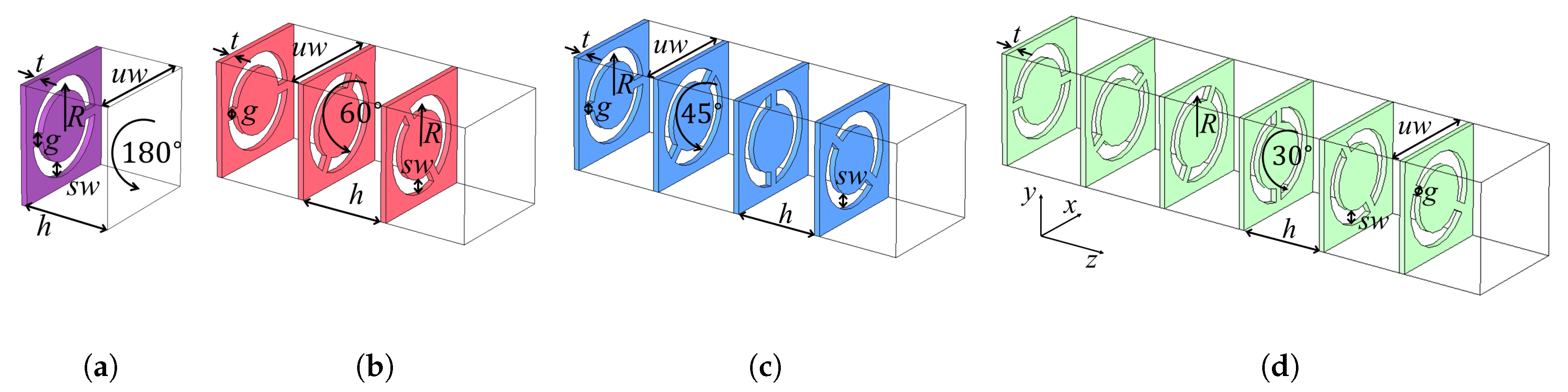
In this work, four different structures with local twist symmetry are studied. The structures are illustrated in Figure 1. In this initial study, the structures are 3D periodic. The different unit cells consisted of different numbers of layers of perforated metallic sheets of a thickness t, separated by an air gap of thickness h. The perforation in the metal consisted of two concentric semi-circular slots, also called CSRRs, of radius, R. The slots had a width , and a metallic bridge of width g connected the metal on each side of the slot. The studied structures were 1-, 3-, 4-, and 6-fold twist-symmetric with 1, 3, 4, and 6 metallic sheets per unit cell, respectively. The twist symmetry was local since only the unit cell was twist-symmetric, and not the full array of CSRRs. Furthermore, the twist symmetry was approximate since only the slots were rotated between adjacent sub-unit cells, and not the entire sub-unit cell. Moreover, since the sub-unit cell exhibited mirror symmetry, the rotation between two adjacent sub-unit cells in the smallest geometrical full unit cell was halved. This means that the rotation between two adjacent sub-unit cells was not , but rather , where m is the order of the twist symmetry. Consequently, the rotation between adjacent sub-unit cells was 180, 60, 45, and 30 in the 1-, 3-, 4-, and 6-fold twist-symmetric structures, respectively.
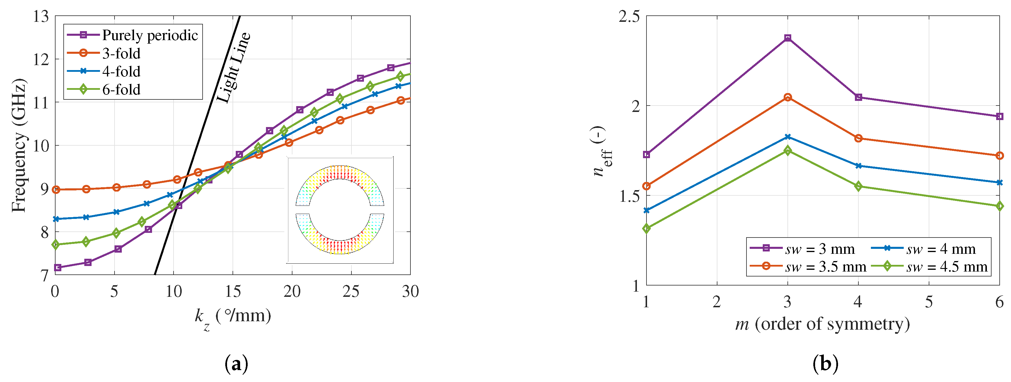
In Figure 2a, the propagation constants for the four structures are represented. In all structures, the lateral periodicity, , was 20 mm, the slots were placed at a radius mm; the slot width, , was 3 mm, and the metallic bridge separating the slots had a width of mm. The separation between the metallic sheets, h, was 4 mm, and the thickness of the metallic sheets, t, was 1 mm. The final implementation (i.e., the lens) will operate with the second mode of the CSRR array. Therefore, only this mode is plotted in Figure 2a. The electric field profile of the second mode is illustrated in the inset of Figure 2a. The mode was odd with respect to the center of the unit cell, in contrast to the first mode, which was even. The odd field distribution was consistent with the excitation employed in the final implementation of the lens. Notably, the electric field pattern in the slot resembled that of a TE-mode in a rectangular waveguide. In fact, the dispersion characteristics of the mode were similar to the ones in a periodically-loaded rectangular waveguide.
From the results of Figure 2a, we can conclude that the phase delay can be controlled by changing the order of the symmetry. In previous works, it has been demonstrated that by increasing the order of twist symmetry, an increased density can be obtained [16,17,18,24]. However, in Figure 2a, the highest density is not necessarily achieved in the structure with the highest order of the symmetry. The reason for this discrepancy with previously-reported results is that, in this study, the sub-unit cell period was kept constant, in contrast to previous studies where the full unit cell periodicity was kept constant. Moreover, the lowest order of twist symmetry (i.e., the three-fold structure) was the most different from the purely-periodic structure. There were two reasons for this. First, the cut-off frequency of the CSRR was shifted upwards in the twist-symmetric structures compared to the purely-periodic structure. The CSRRs in different layers of the structures effectively formed a waveguide with a cut-off frequency. When adjacent layers were rotated, the effective width of the waveguide was reduced, leading to an up-shift in the cut-off frequency. The largest rotation between the two sub-unit cells was obtained in the three-fold structure, and hence, the shift was more severe in this configuration, as the effective width of the waveguide was the smallest. Secondly, the slope of the dispersion curve was more gradual in the twist-symmetric structures compared to the purely-periodic structure. The more gradual slope was caused by the reduced coupling between the CSRRs in different layers for the twist-symmetric structures, compared to the purely-periodic structure. The reduced coupling resulted in a narrower pass band for the second mode [30].
In Figure 2b, the effective refractive index at 11 GHz is presented. The order of symmetry and slot width were swept. The remaining parameters were: mm, mm, mm, mm, and mm. Again, the density of a periodic structure can be controlled by varying the order of the symmetry. The increased density was related to the increased path traveled by the mode, which was forced to revolve in a helical manner around the periodicity axis. The smallest pitch of the helix, and consequently the highest density, was obtained in the three-fold structure. In fact, for increasing order of twist symmetry, we approached the purely-periodic structure as the rotation between subsequent sub-unit cells was decreasing. Additionally, if another geometrical parameter was allowed to vary simultaneously (the slot width, , in this case), a large continuous range of effective indices can be obtained. This control of the phase delay has been previously used to design compact phase shifters [19]. Here, we employed this effect for the design of a flat lens.
2.2. Lens Design Using CSRRs
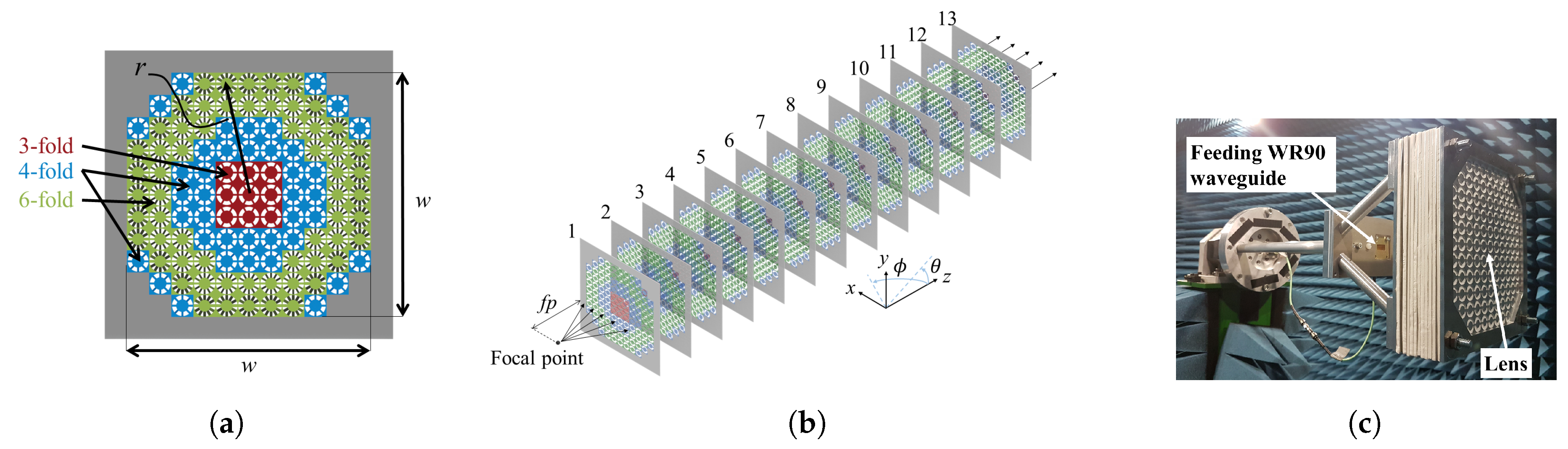
The operation of the lens was conceptually similar to the one of transmit arrays [31,32,33,34]. The phase delay experienced by a wave propagating through the lens was controlled throughout the aperture. The full lens structure is presented in Figure 3. The lens consisted of 13 perforated metallic sheets with a thickness of 1 mm. The sheets were made of aluminum and were separated by 4 mm of air. These sheets were thick enough to remain flat in a practical realization of the lens. However, due to the manufacturing process employed here (laser cutting), the sheets deformed significantly. Therefore, a layer a 4 mm-thick Rohacell 51HF () was added for structural support in between the metallic layers in the realized prototype. The manufactured lens (in the measurement setup) is illustrated in Figure 3c.
The perforation in the metallic sheets consisted of an array of CSRRs. The CSRRs were tailored throughout the aperture so the lens provided the required phase correction necessary to transform a spherical wave emanating from the focal point into a plane wave at the opposite side. A similar configuration has been employed to obtain a wideband linear-to-linear polarization transformation with very low insertion losses [30]. However, in that work, a normally incident plane wave was assumed, and the CSRRs remained unchanged throughout the aperture. Moreover, the first and last layers were different in order to produce a polarization transformation.
Thirteen metallic layers were employed here to produce 3-, 4-, and 6-fold twist-symmetric unit cells. In this way, each twist configuration can fit an integer number of periods into 12 metallic layers. One additional layer, identical to the first, was inserted at the end to ensure that the lens was symmetric and no polarization transformation was performed. If desired, polarization transformation can be integrated into the structure if the first and last layers are different. The phase delay throughout the lens was tailored so that a spherical wave emanating from the focal point, , arrived in phase at the opposite side of the lens. To obtain this, must remain constant throughout the aperture (up to an integer addition of free-space wavelengths), where r is the radial coordinate in the aperture, is the total optical path from the focal point through the lens, and is the effective refractive index of the lens at the position r. The focal point in the designed lens was 130 mm, and the width of the lens, w, was 220 mm. The total thickness of the lens, T, was 61 mm.
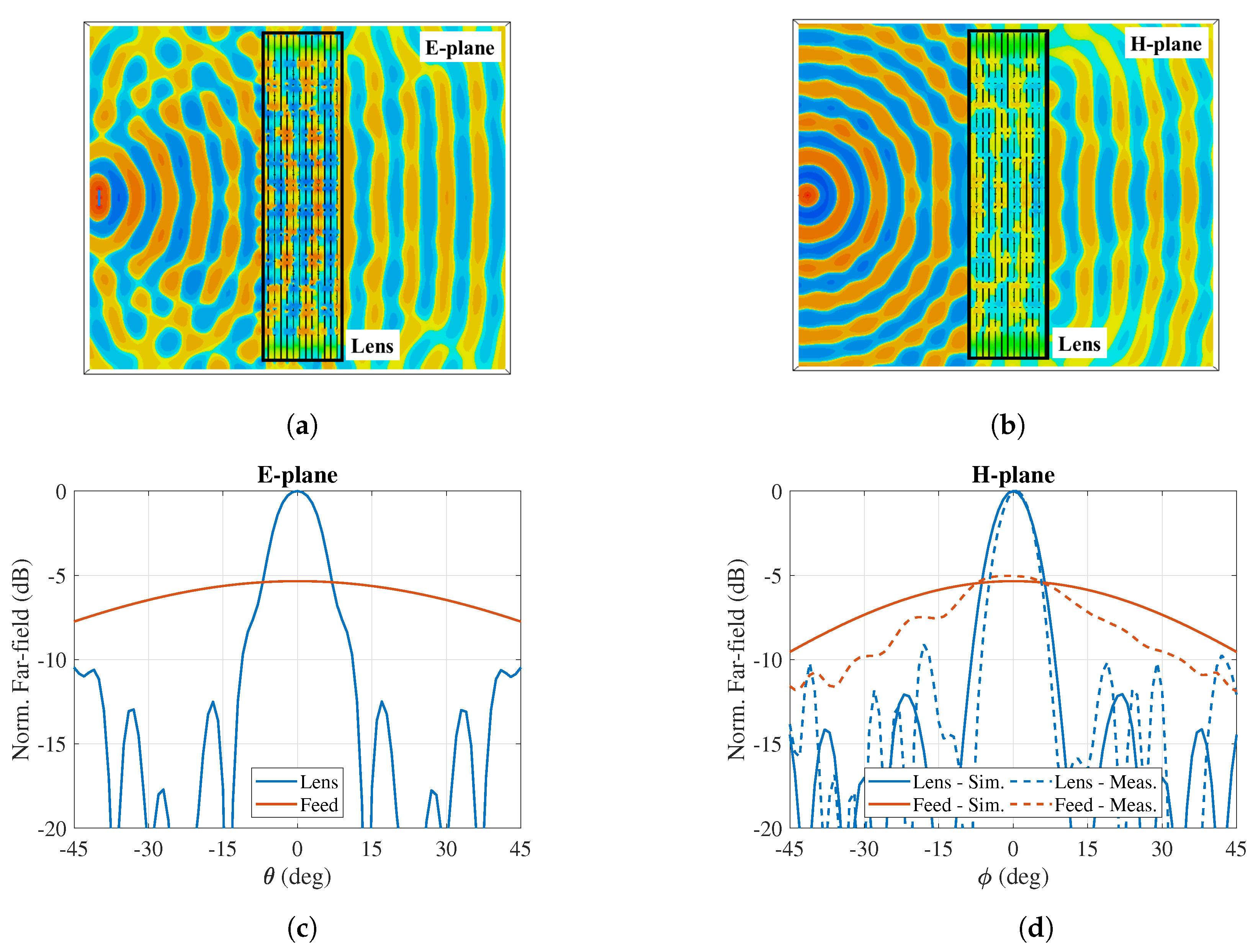
The simulated electric field for the lens, at 11 GHz, excited by a half-wavelength dipole, is presented in Figure 4a,b for the E-plane and H-plane. The lens successfully transformed the spherical wave into a plane wave. To estimate how successful the transformation was, the normalized radiation pattern at 11 GHz, both for the lens fed with a rectangular waveguide (WR90) and for the isolated waveguide (normalized to the maximum realized gain of the full lens antenna), is plotted in Figure 4c,d for the E-plane and H-plane. A clear improvement in the gain of roughly 6 dB was achieved with the lens. The measured H-plane radiation pattern is included in Figure 4d, and the measurement corroborated the simulation. The measured E-plane radiation pattern was distorted by the struts necessary for mounting the antenna in the anechoic chamber. Therefore, the E-plane cut is not presented here. The losses in the metallic sheets were below 1% of the stimulated power in simulations.
3. Discussion
In this work, a periodic structure with local twist symmetry was applied for the design of a fully-metallic lens. First, it was demonstrated that, by introducing different orders of an approximated twist symmetry into the unit cell of a 2D array of CSRRs, the phase delay can be controlled. Moreover, an excellent range of different phase delays can be achieved by only varying the symmetry order. Secondly, a lens was designed by varying the order of the symmetry throughout the aperture, obtaining the required phase delay at each point. The lens consisted of 13 perforated metallic sheets separated by an air gap. The perforation in each sheet was an array of CSRRs. The CSRRs were rotated in each consecutive layer to obtain the twist symmetry. The first and last layers of the lens were identical in order to ensures that no polarization transformation was performed in the lens. However, a polarization transformer can be integrated into the structure by using different orientation of the CSRRs in the first and last layer. Full-wave simulation results showed that the lens structure successfully transformed a spherical wave emanating from the focal point of the lens into a plane wave at the opposite side. The presented concepts can be employed in future design intended for wireless communication networks at high frequencies where fully-metallic directive antennas are desired [20].
4. Materials and Methods
CST Microwave Studio [35] has been used to produce the simulation results in this article. In the study conducted in Section 2.1, the structures were simulated in the Eigenmode Solver of CST, with periodic boundary conditions in all directions. In the study conducted in Section 2.2, the structure was simulated in the Time-Domain Solver of CST. The measurements were carried out in an anechoic chamber. The lens was fed with a WR90 standard waveguide.
Author Contributions
Conceptualization, O.Q.-T.; formal analysis, O.D. and G.V.; methodology, O.D.; visualization, O.D.; writing, original draft preparation, O.D.; writing, review and editing, O.D., O.Q.-T. and G.V.; supervision, O.Q.-T. and G.V.
Funding
This research was partly funded by The French National Research Agency Grant Number ANR-16-CE24-0030, partly by the Vinnova project High-5 (2018-01522), under the Strategic Programme on Smart Electronic Systems, and partly by the Stiftelsen Åforsk project H-Materials (18-302).
Conflicts of Interest
The authors declare no conflict of interest.
References
- Hessel, A.; Chen, M.H.; Li, R.C.M.; Oliner, A.A. Propagation in Periodically Loaded Waveguides with Higher Symmetries. Proc. IEEE 1973, 61, 183–195. [Google Scholar] [CrossRef]
- Crepeau, P.J.; McIsaac, P.R. Consequences of Symmetry in Periodic Structures. Proc. IEEE 1963, 52, 33–43. [Google Scholar] [CrossRef]
- Mittra, R.; Laxpati, S. Propagation in a Wave Guide with Glide Reflection Symmetry. Can. J. Phys. 1965, 43, 353–372. [Google Scholar] [CrossRef]
- Kieburtz, R.; Impagliazzo, J. Multimode Propagation on Radiating Traveling-Wave Structures with Glide-Symmetric Excitation. IEEE Trans. Antennas Propag. 1970, 18, 3–7. [Google Scholar] [CrossRef]
- Cao, W.; Chen, Z.N.; Hong, W.; Zhang, B.; Liu, A. A Beam Scanning Leaky-Wave Slot Antenna with Enhanced Scanning Angle Range and Flat Gain Characteristic Using Composite Phase-Shifting Transmission Line. IEEE Trans. Antennas Propag. 2014, 62, 5871–5875. [Google Scholar] [CrossRef]
- Wu, J.J.; Wu, C.J.; Hou, D.J.; Liu, K.; Yang, T.J. Propagation of Low-Frequency Spoof Surface Plasmon Polaritons in a Bilateral Cross-Metal Diaphragm Channel Waveguide in The Absence of Bandgap. IEEE Photonics J. 2015, 7, 1–8. [Google Scholar] [CrossRef]
- Lyu, Y.L.; Liu, X.X.; Wang, P.Y.; Erni, D.; Wu, Q.; Wang, C.; Kim, N.Y.; Meng, F.Y. Leaky-Wave Antennas Based on Noncutoff Substrate Integrated Waveguide Supporting Beam Scanning From Backward To Forward. IEEE Trans. Antennas Propag. 2016, 64, 2155–2164. [Google Scholar] [CrossRef]
- Quesada, R.; Martín-Cano, D.; García-Vidal, F.; Bravo-Abad, J. Deep-Subwavelength Negative-Index Waveguiding Enabled By Coupled Conformal Surface Plasmons. Opt. Lett. 2014, 39, 2990–2993. [Google Scholar] [CrossRef]
- Quevedo-Teruel, O.; Ebrahimpouri, M.; Kehn, M.N.M. Ultrawideband Metasurface Lenses Based on Off-Shifted Opposite Layers. IEEE Antennas Wirel. Propag. Lett. 2016, 15, 484–487. [Google Scholar] [CrossRef]
- Quevedo-Teruel, O.; Miao, J.; Mattsson, M.; Algaba-Brazalez, A.; Johansson, M.; Manholm, L. Glide-Symmetric Fully Metallic Luneburg Lens for 5G Communications at Ka-Band. IEEE Antennas Wirel. Propag. Lett. 2018, 17, 1588–1592. [Google Scholar] [CrossRef]
- Padilla, P.; Herrán, L.; Tamayo-Domínguez, A.; Valenzuela-Valdés, J.; Quevedo-Teruel, O. Glide Symmetry to Prevent The Lowest Stopband of Printed Corrugated Transmission Lines. IEEE Microw. Wirel. Compon. Lett. 2018, 28, 1–3. [Google Scholar] [CrossRef]
- Ebrahimpouri, M.; Quevedo-Teruel, O.; Rajo-Iglesias, E. Design Guidelines for Gap Waveguide Technology Based on Glide-Symmetric Holey Structures. IEEE Microw. Wirel. Compon. Lett. 2017, 27, 542–544. [Google Scholar] [CrossRef]
- Ebrahimpouri, M.; Brazalez, A.A.; Manholm, L.; Quevedo-Teruel, O. Using Glide-Symmetric Holes to Reduce Leakage Between Waveguide Flanges. IEEE Microw. Wirel. Compon. Lett. 2018, 28, 473–475. [Google Scholar] [CrossRef]
- Ebrahimpouri, M.; Rajo-Iglesias, E.; Sipus, Z.; Quevedo-Teruel, O. Cost-Effective Gap Waveguide Technology Based on Glide-Symmetric Holey EBG Structures. IEEE Trans. Microw. Theory Tech. 2018, 66, 927–934. [Google Scholar] [CrossRef]
- Rajo-Iglesias, E.; Ebrahimpouri, M.; Quevedo-Teruel, O. Wideband Phase Shifter in Groove Gap Waveguide Technology Implemented With Glide-Symmetric Holey EBG. IEEE Microw. Wirel. Compon. Lett. 2018, 28, 476–478. [Google Scholar] [CrossRef]
- Dahlberg, O.; Mitchell-Thomas, R.; Quevedo-Teruel, O. Reducing the Dispersion of Periodic Structures with Twist and Polar Glide Symmetries. Sci. Rep. 2017, 7, 10136. [Google Scholar] [CrossRef] [Green Version]
- Ghasemifard, F.; Norgren, M.; Quevedo-Teruel, O. Twist and Polar Glide Symmetries: An Additional Degree of Freedom to Control The Propagation Characteristics of Periodic Structures. Sci. Rep. 2018, 8, 11266. [Google Scholar] [CrossRef]
- Dahlberg, O.; Ghasemifard, F.; Valerio, G.; Quevedo-Teruel, O. Propagation Characteristics of Periodic Structures Possessing Twist and Polar Glide Symmetries. EPJ Appl. Metamater. 2019, in pressing. [Google Scholar] [CrossRef]
- Quevedo-Teruel, O.; Dahlberg, O.; Valerio, G. Propagation in Waveguides With Transversal Twist-Symmetric Holey Metallic Plates. IEEE Microw. Wirel. Compon. Lett. 2018, 28, 1–3. [Google Scholar] [CrossRef]
- Quevedo-Teruel, O.; Ebrahimpouri, M.; Ghasemifard, F. Lens Antennas for 5G Communications Systems. IEEE Commun. Mag. 2018, 56, 36–41. [Google Scholar] [CrossRef]
- Cavallo, D.; Felita, C. Analytical Formulas for Artificial Dielectrics with Nonaligned Layers. IEEE Trans. Antennas Propag. 2017, 65, 5303–5311. [Google Scholar] [CrossRef]
- Cavallo, D. Dissipation Losses in Artificial Dielectric Layers. (Early Access) IEEE Trans. Antennas Propag. 2018, 66. [Google Scholar] [CrossRef]
- Chang, T.; Kim, J.U.; Kang, S.K.; Kim, H.; Kim, D.K.; Lee, Y.H.; Shin, J. Broadband Giant-Refractive-Index Material Based on Mesoscopic Space-Filling Curves. Nat. Commun. 2016, 7, 12661. [Google Scholar] [CrossRef]
- Chen, Q.; Ghasemifard, F.; Valerio, G.; Quevedo-Teruel, O. Modeling and Dispersion Analysis of Coaxial Lines With Higher Symmetries. IEEE Trans. Microw. Theory Tech. 2018, 66, 1–8. [Google Scholar] [CrossRef]
- Valerio, G.; Sipus, Z.; Grbic, A.; Quevedo-Teruel, O. Accurate Equivalent-Circuit Descriptions of Thin Glide-Symmetric Corrugated Metasurfaces. IEEE Trans. Antennas Propag. 2017, 65, 2695–2700. [Google Scholar] [CrossRef]
- Valerio, G.; Ghasemifard, F.; Sipus, Z.; Quevedo-Teruel, O. Glide-Symmetric All-Metal Holey Metasurfaces for Low-Dispersive Artificial Materials: Modeling and Properties. IEEE Trans. Microw. Theory Tech. 2018, 66, 1–14. [Google Scholar] [CrossRef]
- Ghasemifard, F.; Norgren, M.; Quevedo-Teruel, O. Dispersion Analysis of 2-D Glide-Symmetric Corrugated Metasurfaces Using Mode-Matching Technique. IEEE Microw. Wirel. Compon. Lett. 2018, 28, 1–3. [Google Scholar] [CrossRef]
- Mesa, F.; Rodríguez-Berral, R.; Medina, F. On the Computation of the Dispersion Diagram of Symmetric One-Dimensionally Periodic Structures. Symmetry 2018, 10, 307. [Google Scholar] [CrossRef]
- Palomares-Caballero, A.; Padilla, P.; Valenzuela-Valdes, J.; Quevedo-Teruel, O. Twist and Glide Symmetries for Helix Antenna Design and Miniaturization. Symmetry 2019, 11, 349. [Google Scholar] [CrossRef]
- Wei, Z.; Cao, Y.; Fan, Y.; Yu, X.; Li, H. Broadband Polarization Transformation via Enhanced Asymmetric Transmission Through Arrays of Twisted Complementary Split-Ring Resonators. Appl. Phys. Lett. 2011, 99, 221907. [Google Scholar] [CrossRef]
- Pfeiffer, C.; Grbic, A. Millimeter-Wave Transmitarrays for Wavefront and Polarization Control. IEEE Trans. Microw. Theory Tech. 2013, 61, 4407–4417. [Google Scholar] [CrossRef]
- Pfeiffer, C.; Grbic, A. Bianisotropic Metasurfaces for Optimal Polarization Control: Analysis and Synthesis. Phys. Rev. Appl. 2014, 2, 044011. [Google Scholar] [CrossRef]
- Padilla, P.; Muñoz-Acevedo, A.; Sierra-Castañer, M. Passive Planar Transmit-Array Microstrip Lens for Microwave Purpose. Microw. Opt. Technol. Lett. 2010, 52, 940–947. [Google Scholar] [CrossRef]
- Yeap, S.B.; Qing, X.; Chen, Z.N. 77-GHz Dual-Layer Transmit-Array for Automotive Radar Applications. IEEE Trans. Antennas Propag. 2015, 63, 2833–2837. [Google Scholar] [CrossRef]
- CST Microwave Studio, Version: 2017. Available online: http://www.cst.com/ (accessed on 20 February 2019).
Figure 1.
Simulated CSRRs with local twist symmetry. Studied structures: (a) purely periodic (), (b) 3-fold, (c) 4-fold, and (d) 6-fold.
Figure 1.
Simulated CSRRs with local twist symmetry. Studied structures: (a) purely periodic (), (b) 3-fold, (c) 4-fold, and (d) 6-fold.

Figure 2.
(a) Simulated propagation constant with dimensions: mm, mm, mm, 1.5 mm, mm, and mm. (b) Simulated effective refractive index at 11 GHz with dimensions: mm, mm, 1.5 mm, mm, and mm.
Figure 2.
(a) Simulated propagation constant with dimensions: mm, mm, mm, 1.5 mm, mm, and mm. (b) Simulated effective refractive index at 11 GHz with dimensions: mm, mm, 1.5 mm, mm, and mm.

Figure 3.
(a–b) Layout of the lens: (a) front view, and (b) perspective view. The distance between the metallic sheets is exaggerated for increased clarity. (c) Measurement setup in the anechoic chamber.
Figure 3.
(a–b) Layout of the lens: (a) front view, and (b) perspective view. The distance between the metallic sheets is exaggerated for increased clarity. (c) Measurement setup in the anechoic chamber.

Figure 4.
Simulated E-field and far-field of the lens. (a–b) x-component of the electric field excited by an x-oriented half-wavelength dipole placed in the focal point of the lens: (a) E-plane and (b) H-plane. (c–d) Normalized radiation pattern of the lens excited with a rectangular waveguide (WR90) placed at the focal point of the lens: (c) E-plane and (d) H-plane. The measurement of the H-plane cut is included as well. The width, w, of the lens is 220 mm, and the focal point is 130 mm from the first layer. The separation between the sheets is 4 mm, and the thickness of the metallic sheets is 1 mm.

© 2019 by the authors. Licensee MDPI, Basel, Switzerland. This article is an open access article distributed under the terms and conditions of the Creative Commons Attribution (CC BY) license (http://creativecommons.org/licenses/by/4.0/).
Share and Cite
MDPI and ACS Style
Dahlberg, O.; Valerio, G.; Quevedo-Teruel, O. Fully Metallic Flat Lens Based on Locally Twist-Symmetric Array of Complementary Split-Ring Resonators. Symmetry 2019, 11, 581. https://0-doi-org.brum.beds.ac.uk/10.3390/sym11040581
AMA Style
Dahlberg O, Valerio G, Quevedo-Teruel O. Fully Metallic Flat Lens Based on Locally Twist-Symmetric Array of Complementary Split-Ring Resonators. Symmetry. 2019; 11(4):581. https://0-doi-org.brum.beds.ac.uk/10.3390/sym11040581
Chicago/Turabian StyleDahlberg, Oskar, Guido Valerio, and Oscar Quevedo-Teruel. 2019. "Fully Metallic Flat Lens Based on Locally Twist-Symmetric Array of Complementary Split-Ring Resonators" Symmetry 11, no. 4: 581. https://0-doi-org.brum.beds.ac.uk/10.3390/sym11040581
Note that from the first issue of 2016, this journal uses article numbers instead of page numbers. See further details here.