Article

On Aluminum Honeycomb Impact Attenuator Designs for Formula Student Competitions

1
Department of Applied Mechanics, Faculty of Mechanical Engineering, VSB-Technical University of Ostrava, 70833 Ostrava, Czech Republic
2
Department of Machining, Assembly and Engineering Metrology, Faculty of Mechanical Engineering, VSB-Technical University of Ostrava, 70833 Ostrava, Czech Republic
3
Institute of Transport, Faculty of Mechanical Engineering, VSB-Technical University of Ostrava, 70833 Ostrava, Czech Republic
*
Author to whom correspondence should be addressed.
Submission received: 7 September 2020 / Revised: 17 September 2020 / Accepted: 24 September 2020 / Published: 8 October 2020
(This article belongs to the Special Issue Symmetry in Mechanical Engineering Ⅱ)

Abstract

:
The use of impact attenuators (IA) is important for vehicles as they absorb the kinetic energy exerted from the car crashes to protect the drivers from any possible injuries. Under the framework of the Formula Student (FS) competition, we investigate various designs of IA made of aluminum honeycomb material. Specifically, the crushing behavior of the honeycomb structure is investigated from the theoretical point of view and later verified with numerical simulations. To achieve the desired crushing behavior of the aluminum honeycomb structure, apart from the so-called pre-crushing method, another way to pre-process the aluminum honeycomb is proposed. Modification on the aluminum honeycomb is done in a symmetric manner to ensure the same uniform crushing behavior on the two sides of the mirror plane of the car. Different variations presented in this paper shed a light on future aluminum honeycomb IA designs in the context of FS competitions.

1. Introduction

Formula Student (FS) is a multinational auto racing competition established to foster university students under the framework of a semi-professional motorsport competition. Joining this competition, students can improve their business and engineering skills while attempting to deliver a racing car to compete with others from different universities [1].
It is possible to construct the vehicle with designed or commercially available components. Among the designable components, there are the bell crank, suspension link, rear upright, etc. [2,3,4,5]. The impact attenuator (IA) is as well in this category, and is defined as a deformable, energy-absorbing device mounted forward of the car’s front [6]. In practice, porous materials are generally suitable for impact energy absorption due to their internal material structure which allows the progressive collapse under impact loading. Hence, structures such as polymeric foams or aluminum honeycombs are the most favored among FS teams. Due to the ease of access, novice FS teams often purchase the standard, commercially available IA made of foam as shown in Figure 1. The standard IA was also tested in [7]. It was found that the standard IA can be further reduced in size, thus its weight, and still it can meet the competition requirements.
As composite materials become widely available, considerable endeavor is put into the design of composite IA among FS teams and the research community in general. Nevertheless, in 1983 NASA came up with a study of energy-absorbing properties of tubes under compression [9]. Examinations were made for aluminum, glass-epoxy, graphite-epoxy, and aramid-epoxy tubes. Chamfering or notching was suggested to reduce the peak load during the impact. In addition, post-crushing integrity and failure mechanisms were examined. Composite tubes were recently studied for their energy-absorbing properties in [10]. The influence of tube diameter, winding angles, and wall thickness on energy absorption was examined, suggesting that for a larger tube diameter, the absorbed energy is higher. Then, the winding angle of 35 degrees showed more energy absorbed for less compressive strength than other angles. The utilization of composite material (including carbon fibers) was also studied in [11,12,13]. The papers brought insights about IA design, testing, numerical analysis, and optimization. Optimization methods examined in [11] allowed authors to design an IA with 14% better energy absorption.
Another group of IA is welded thin-walled structures. Such designs were examined for their impact performance in [14,15,16]. All designs met FS competition requirements, suggesting another promising method of designing IA. Indeed, this solution is possibly the most feasible and economical in terms of numerical simulation and physical tests.
Owing to the maturity of additive technologies, a lot of studies examined 3D-printed lattice structures of various materials for their energy-absorbing properties. Existing literature suggests that a lot of effort was put into examinations of aluminum alloy lattice structures, made of AlSi10Mg. The authors in [17,18,19] examined lattice structure designs for energy absorbers manufactured by selective laser melting technology (SLM). The studies provide insights about lattice failure mechanisms, the influence of lattice cell design, and print imperfections on structure performance under impact. The authors in [17,20] found that the heat treatment of AlSi10Mg lattice structure increases its strain capacity suggesting that more energy can be absorbed. Further investigation of lattice cells in [19,21] found that for the same relative density of structure, different types of lattices have different impact resistance. This is caused by different failure modes for different lattice cell designs.
Another favorite material for SLM is alloyed titanium. Lattice structures of titanium alloys were investigated in [22,23,24]. An interesting combination of materials was investigated in [22]. The authors examined sandwich panels of carbon fiber-reinforced polymer (CFRP) faces which were constructed of two types of core—aluminum honeycomb and titanium alloy (Ti64) lattice structure. It was found that panels with aluminum honeycomb cores have comparable impact resistance as panels with Ti64 lattice structure cores. The disadvantage of panels with Ti64 lattice cores is its double weight compared to panels with aluminum honeycomb. Panels with Ti64 lattice core showed less dent depth and more localized damage area. That is probably caused by the brittle failure mechanism of Ti64 lattices leading to unstable energy-absorbing behavior. Hence, the use of titanium alloy lattices for energy absorbers needs to be further examined. In [23,25], optimum design strategies for Kagome structures were investigated. Prediction of the failure of SLM-manufactured lattice structures with a wide range of slenderness ratios and different failure modes was performed. Failure modes and failure locations of Kagome structures were also predicted. Results show that Kagome structures indicated superior performance compared to lattice structures.
Among widely printed materials, there is also stainless steel 316L. The energy-absorbing performance under compression of the SLM-manufactured steel 316L lattice structure was investigated in [26,27]. An interesting study was presented in [28], where an SLM-manufactured aluminum lattice structure coated by ceramic was examined for its energy-absorbing properties. A combination of increasing truss angle and oxide coating thickness results in improvements in the compressive strength, energy absorbed per volume and per mass. Improvement in the performance of the structure is caused by the change of failure mode from mid-strut buckling to a hinge kinking mode as the oxide coating thickness increases. In terms of energy absorption, the best performing lattice materials in the study are comparable with the best available cellular materials in the existing literature.
Furthermore, it is worth mentioning the honeycomb structure, which is well known for its remarkably lightweight property, relatively high strength-to-weight ratio and energy-absorbing ability. Honeycomb structures can be metallic (usually aluminum) or nonmetallic (paper reinforced with plastic), with similar unique crushing behavior. The most utilized honeycomb structure is the sandwich shape, as investigated in [29,30], in which the honeycomb layers are glued in between metal sheets to make the airplane walls, vehicle bodies, etc. The aluminum honeycomb block specifically designed for FS competition is available on the website of the Plascore company [31]. Thus, a number of teams purchased the product, tested, and deployed it in their car. As a matter of fact, owing to the complexity of the simulations, a few studies attempted to numerically study the crushing behavior of the honeycomb block in the scope of FS competitions [32,33,34]. An unusual IA design made from aluminum honeycomb panels and aluminum sheets was examined in [33], which met the competition requirements. For purposes of FS competition, in [34], an aluminum honeycomb IA was examined and compared with a hollow truncated thin-walled pyramid and a hybrid IA made from honeycomb panels bonded to several CFRP plates. It was found that all designs met FS requirements and the hybrid IA was the lightest and the most energy-absorbing. The collapse of aluminum honeycomb structures under compression loading was also examined in [35,36]. The authors in [36] suggested various honeycomb cell shapes which, under out-of-plane compression, performed better than conventional honeycombs. Another interesting design of an energy-absorbing structure utilizing honeycombs was studied in [37]. The authors examined an IA of aluminum honeycomb internally reinforced by corrugated aluminum sheets. Significant enhancement of absorbed energy was found compared to the performance of bare honeycomb or corrugated sheet. As honeycombs are not always loaded purely in-plane or out-of-plane, examination in [38] showed honeycomb performance when inclined cells were compressed, and hence loaded under non-ideal conditions. Results suggested that the angle of inclination dictates the failure mode of cells and that plateau stress is influenced by the inclination angle of cells. The larger cell inclination, the more the plateau stress is reduced leading to less energy to be absorbed. Studies of an innovative approach, aluminum honeycomb reinforced with CFRP tubes in cells, were reported in [39,40]. The authors conducted studies of impact behavior of aluminum honeycombs with CFRP tubes in cells. Results showed an increase of about 60% absorbed energy compared to bare aluminum honeycomb. For designing the IA for FS competition, not only is the absorbed energy the criterion, but there are also average and peak accelerations during the impact. It should be noted that for the majority of the cited studies, the acceleration values were not reported. Hence, suggestions of cited studies should serve future designers as a guide and an encouragement to investigate the real impact properties of their IA design.
For FS vehicles, it is also necessary to design a backing plate for the IA which is called the anti-intrusion plate (AIP). Standard options given by rules are steel or aluminum sheets of specific thicknesses. As the mass reduction of the vehicle is desirable, studies were conducted to see the performance of AIP of different materials. The most frequently investigated material in terms of the strength-to-weight ratio is carbon fiber composite. The authors in [41,42] performed examinations of cross-ply unidirectional polyethylene fiber composite under dynamic loading utilizing the bi-material model to evaluate the failure and energy absorption modes. In [43], the thermoplastic composite was evaluated for its penetration resistance-deriving method for the quick design of fiber volume fraction and plate thickness. CFRP plates reinforced by aluminum sheets were tested for their perforation resistance in [44]. Mainly the protection effect of aluminum sheets was investigated. It was found that aluminum sheet helps to distribute the loading from an impact more evenly over CFRP layers contributing to the overall perforation resistance. Regarding the AIP design, suggestions from cited studies can only serve as a guide for the design of AIP for FS vehicles. Further examination of materials and real impact behavior with specific IA used is needed.
Inspired by the above studies, we decide to numerically investigate the crushing behavior of IAs made of aluminum honeycomb. Differing itself from existing works, herein, we simulate the honeycomb block with detailed cell walls in association with a portion of the car’s front, as an effort to replicate the real physical crash test that is described in the FS rules. Consequently, our main contributions are as follows:
  • We propose an alternative way to process the honeycomb block instead of pre-crushing for energy-absorbing purposes and conducted numerical simulations to verify the concept.
  • From the simulation results, we are able to describe the insights of the crushing process which can be useful for future development.
Furthermore, readers can refer to the Figure 2 below for the workflow diagram of this paper:

2. Materials and Methods
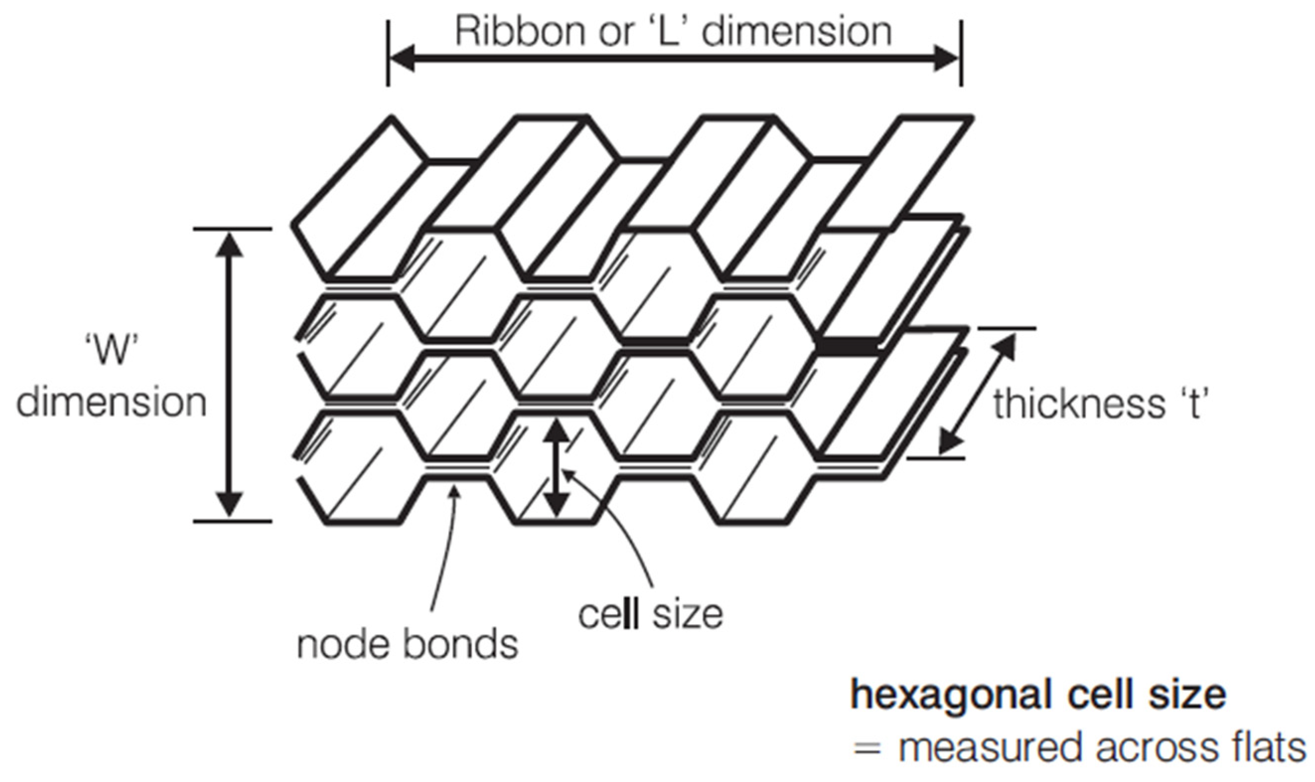
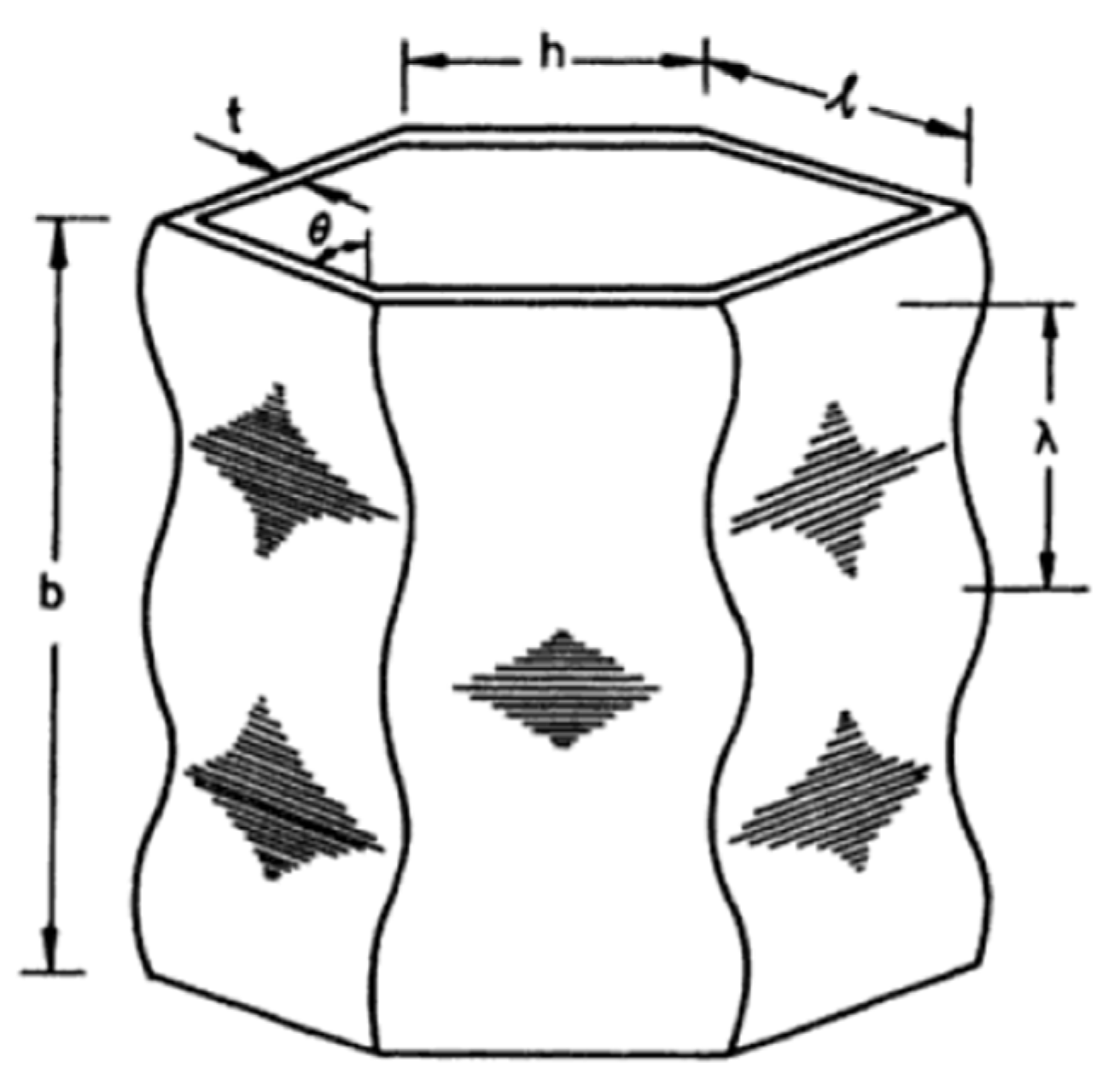
In this section, we introduce the honeycomb materials and the typical properties of the aluminum honeycomb making it feasible for shock-absorbing application. The information of the aluminum honeycomb block is taken from real products of the Plascore company and later modeled accordingly for numerical simulations.

2.1. Terminologies

To manufacture the aluminum honeycomb, the corrugated aluminum sheets are joined by means of resistance welding. Inheriting from such a process, the in-between thicknesses (node bonds) are two times the incline walls. It should be noted that for our numerical simulations, we model the node bonds with double thickness according to Figure 3 taken from [45] below. With regard to [46], the single-thickness walls collapse following the same failure mechanism but sooner than the double-thickness walls.
For our study, we consider two profiles; namely PAMG-PA3-3.0-3⁄8-20-N-5052 (profile A) and PAMG-PA3-5.4-3⁄8-40-N-5052 (profile B) in the Plascore’s catalog. The naming explains, in order: Aerospace grade aluminum-PA3 corrosion coating-Density-Cell thickness x10,000-Not perforated (N)-Alloy of the material (5052 Al), [47]. It should be noted that only the density and geometric data are employed for modeling the honeycomb cells made with 5052 Al. Thus, listed in Table 1 below are our considered details.
Applications of aluminum honeycomb for energy absorption are mostly with impact pressure applied on the out-of-plane surface which is prescribed by W and L.

2.2. Properties

The aluminum honeycomb is orthotropic material. Its applications span widely in aerospace, automobile, marine, and military fields, owing to its lightweight property; excellent energy-absorbing ability; and high strength-to-weight and stiffness-to-weight ratios. Besides, according to [45], it possesses excellent and constant crush strength; high structural integrity; high fatigue, corrosion, and flammability resistance; etc.

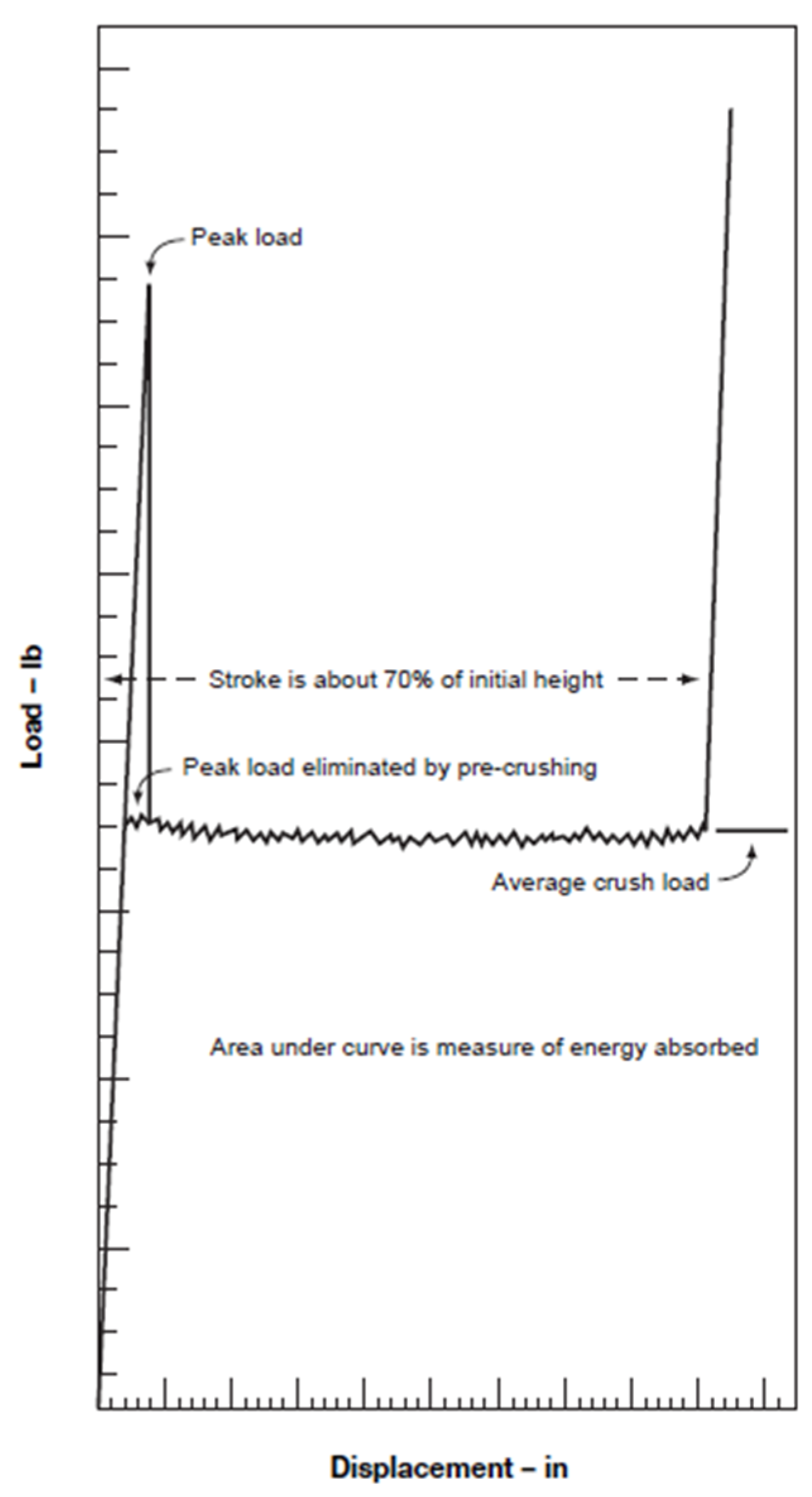
2.2.1. Crushing Behavior

For out-of-plane compressive loading, compression applied perpendicularly to the out-of-plane surface, after the structure reaches its ultimate strength, the crushing behavior follows the crush curve as shown in Figure 4 below.
However, the peak load owing to the initialization of the collapse is harmful for under-protected structures [14]. Thus, this peak load is eliminated by a so-called pre-crushing process and what remains is a uniform crush curve.
It should be noted that Figure 4 is taken from the manual of the manufacturer to explain in general the effect of pre-crushing on the crushing behavior of the material. Thus, specific values and units on the axes are not within our interest.
In the next subsection, we discuss the collapse mechanism of the honeycomb cell walls and explain the benefit of the pre-crushing process.

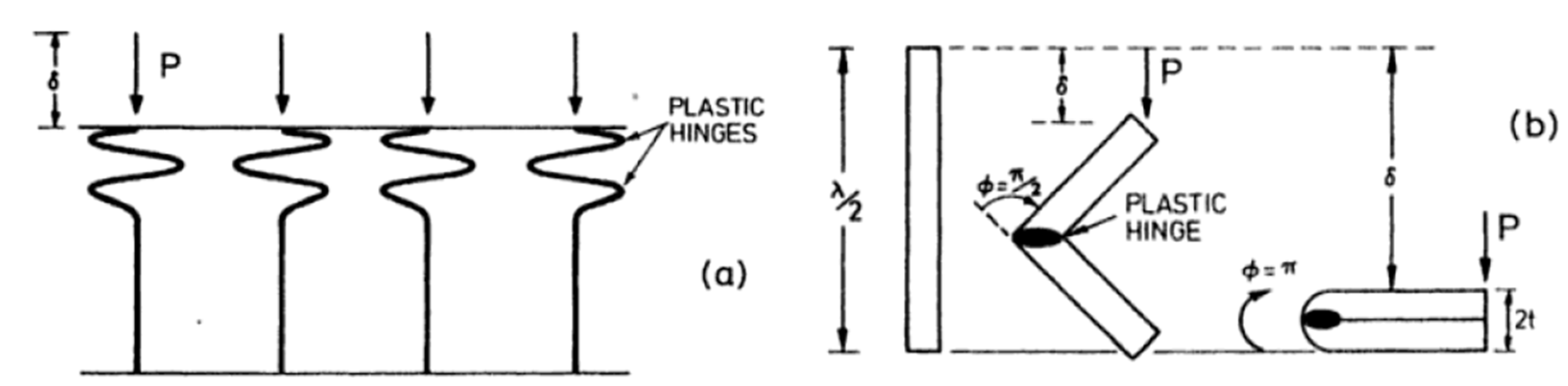
2.2.2. Collapse Mechanism

Under out-of-plane compressive loading, at first, the thin-walled cells elastically buckle within the free spaces between the cells, indicated by the rhombus shapes in Figure 5. Further loaded beyond the yield limit, the structure starts to “dimple” (cell walls are hinged among the free space between cells) leading to the plastic collapse of the whole structure [35,46], Figure 6.
This uniform plastic collapse process happens along the thickness of the honeycomb block and corresponds to the flat portion of the curve in Figure 4. During this time, the kinetic energy that the crashing vehicle exerts will be converted uniformly to the deformation energy of the honeycomb block.
The pre-crushing process is able to cut out the peak load because it introduces some initial plastic buckling to the honeycomb block, thus allowing the plastic collapse of the whole structure to happen without the need of initiation from the peak load.
In the next section, we discuss analytical and numerical approaches for computing the IA design.

2.3. Analytical Estimation of Impact Values

Given that a car of m = 300 kg travels at vimpact = 7 m.s−1 to hit a rigid wall. Design an IA that can fully stop the car by absorbing at least Ke = 7350 J of the kinetic energy that the car exerts. The decelerations of such event are not higher than aaverage = 20 g’s on average and apeak = 40 g’s at peak, with g = 9.81 m.s−2. No part of the AIP deflects more than 25 mm from its original position.
  • Kinetic energy:
    K e = 1 2 m v i m p a c t 2 = 1 2 · 300 · ( 7 ) 2 = 7350   J ;
  • Approximation of impact time:
    t i m p a c t = v i m p a c t a a v e r a g e = 7 20 · 9.81 = 0.0357 s ;
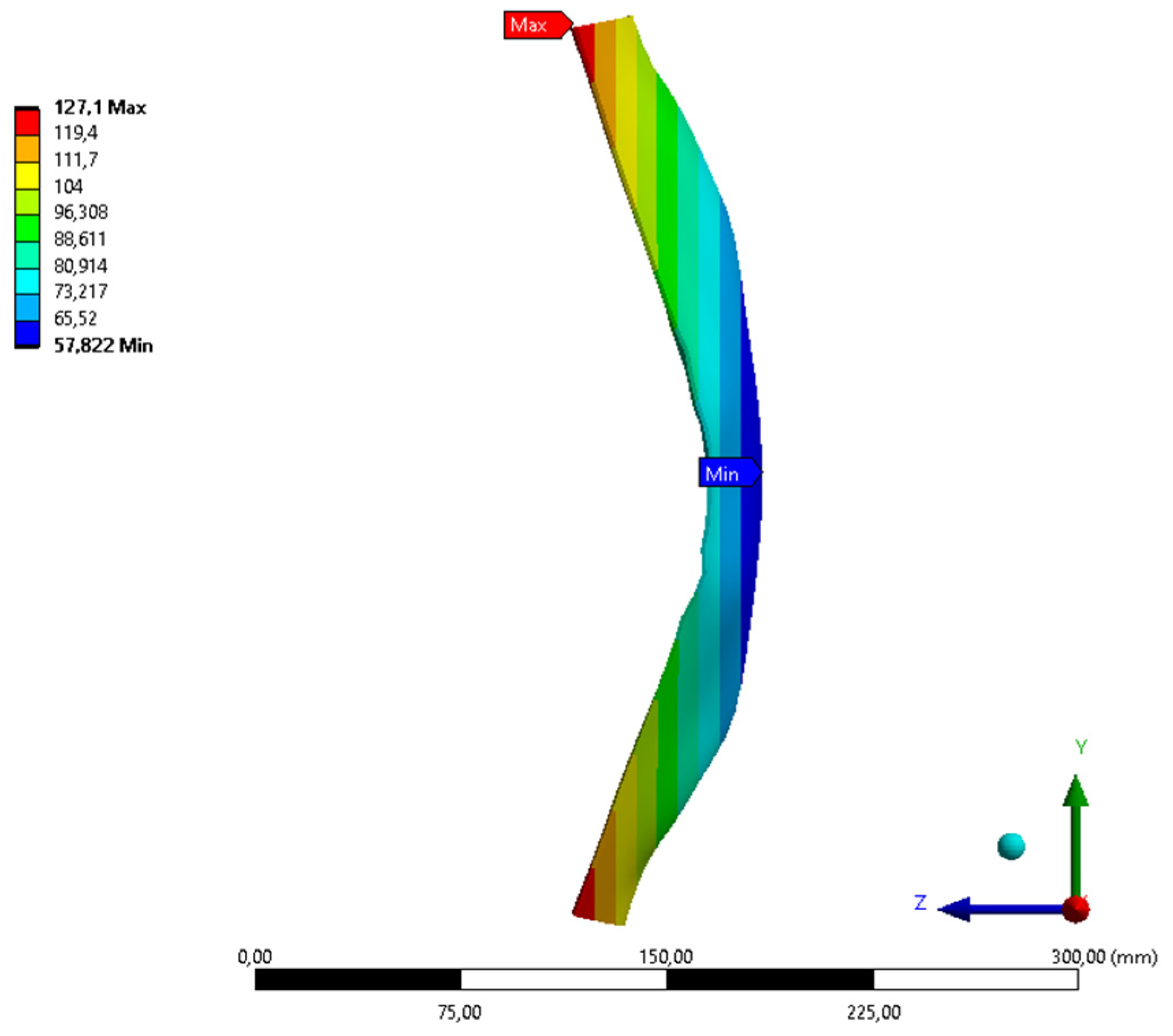
  • Deflection of AIP is measured in ANSYS.
There are three versions of IA presented. According to the analytical result, the simulation time was preset to 0.04 s for the first two versions, and 0.055 s for the final version. It should be noted that since the simulation time is approximated, we do not know in advance during that period whether the vehicle will be fully stopped or not. This issue is later indicated by the fact that not all the deceleration–time curves converge to zero, as shown later in Section 3.

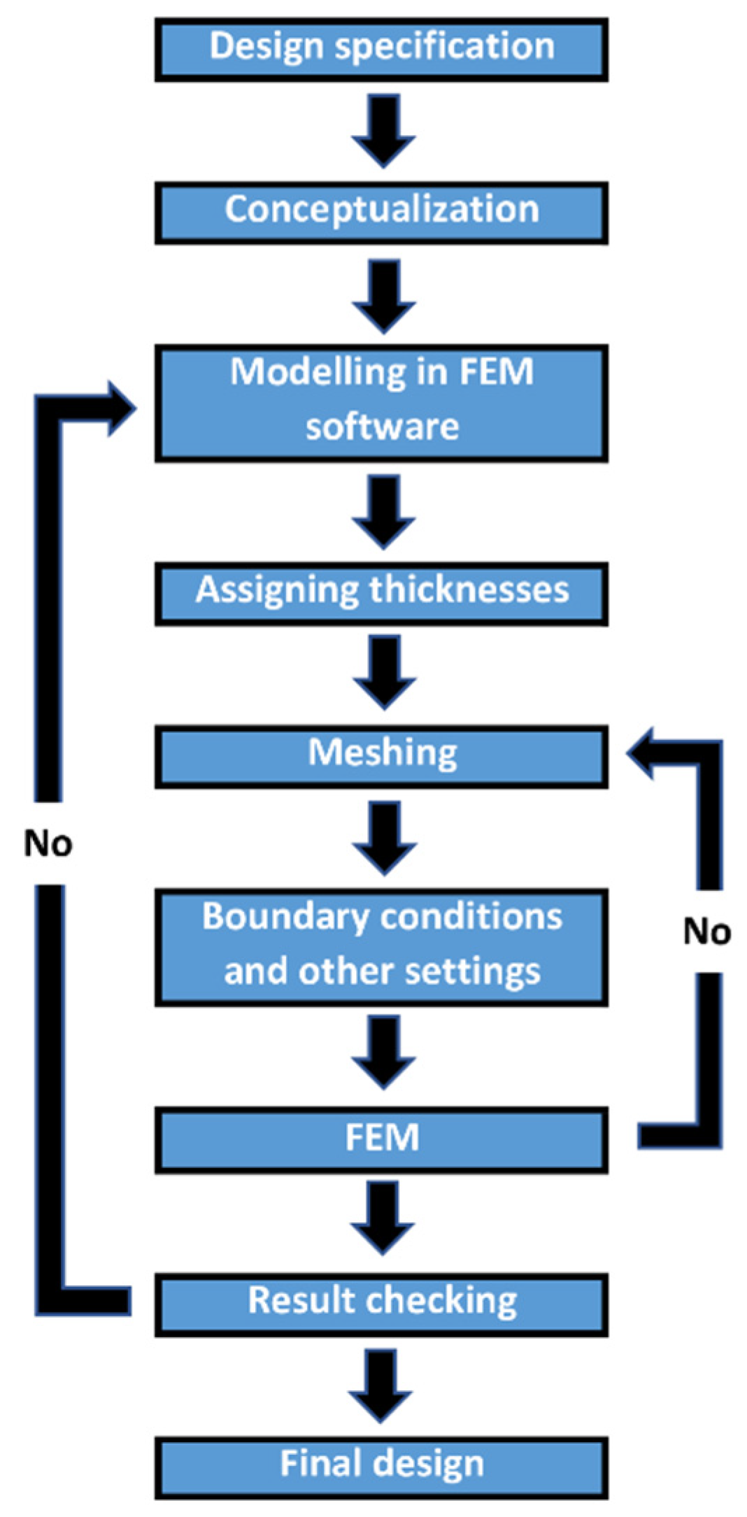
2.4. Numerical Solution of Impact Behavior

We used the ANSYS Workbench for Researcher, Version 18.2 with four processors. In addition, the impact simulations were conducted using the explicit dynamic module. Thus, the below design and setting were conducted following the ANSYS format.

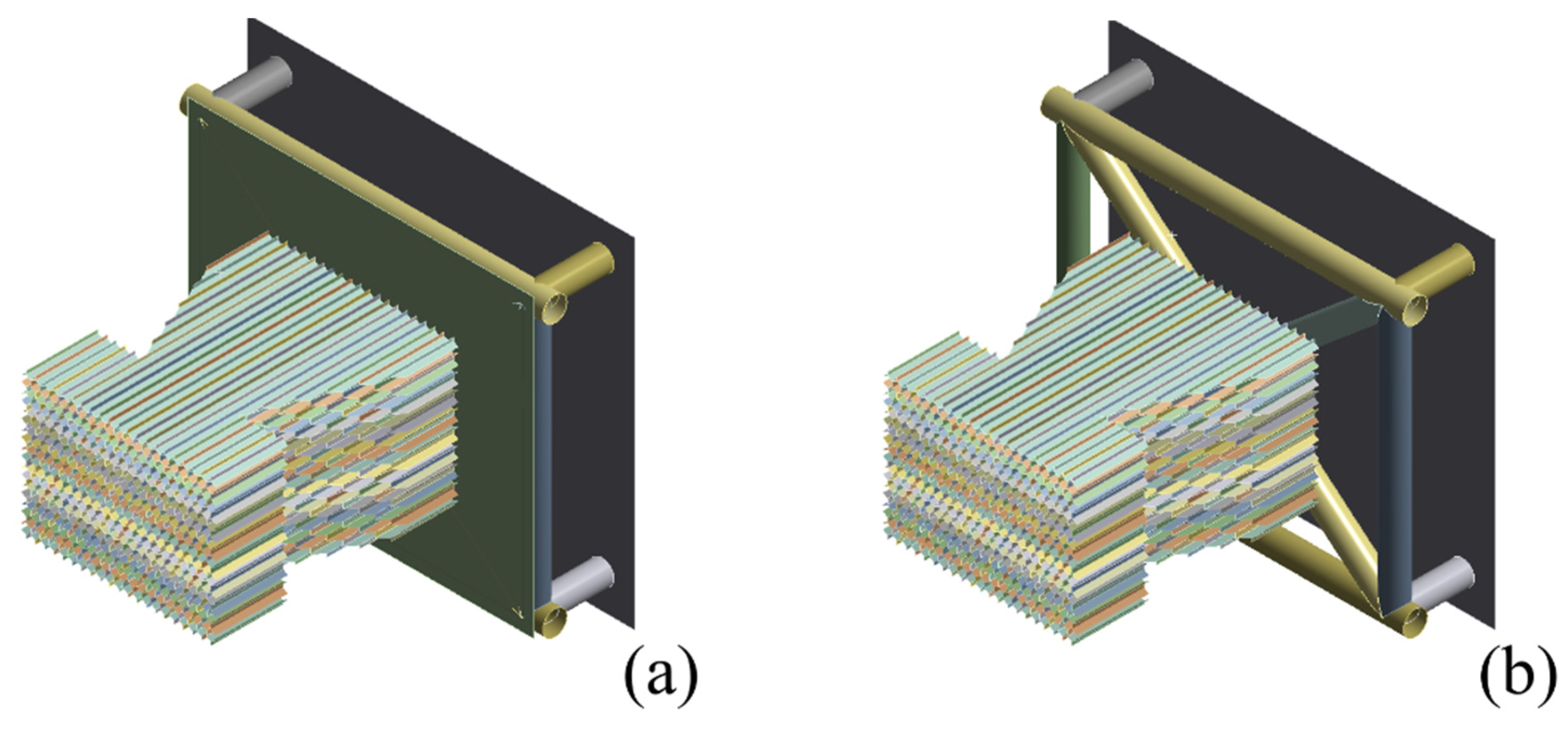
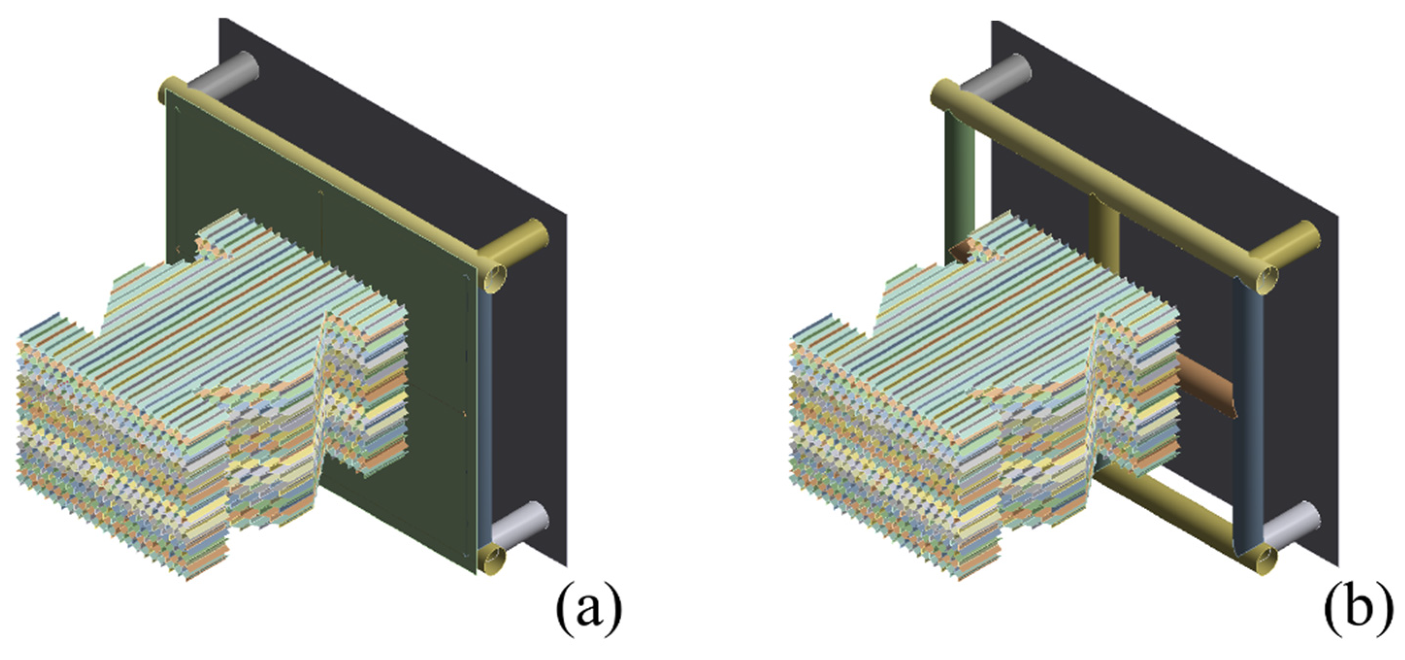
2.4.1. Designs for Simulations

According to the rules [6], in Figure 7, we designed a portion of the car’s front for the explicit dynamic simulations. There is an impact attenuator assembly which includes the honeycomb IA, the AIP, and the rectangular front bulkhead (FB). The IA assembly has the plane of symmetry to be xzO. From the finite element analysis (FEA) perspective, the model was constructed of shell elements with zero thickness, thus allowing us to flexibly change the thicknesses while saving a considerable amount of modeling and computing time.
From left to right, to the -Oz axis direction, there are:
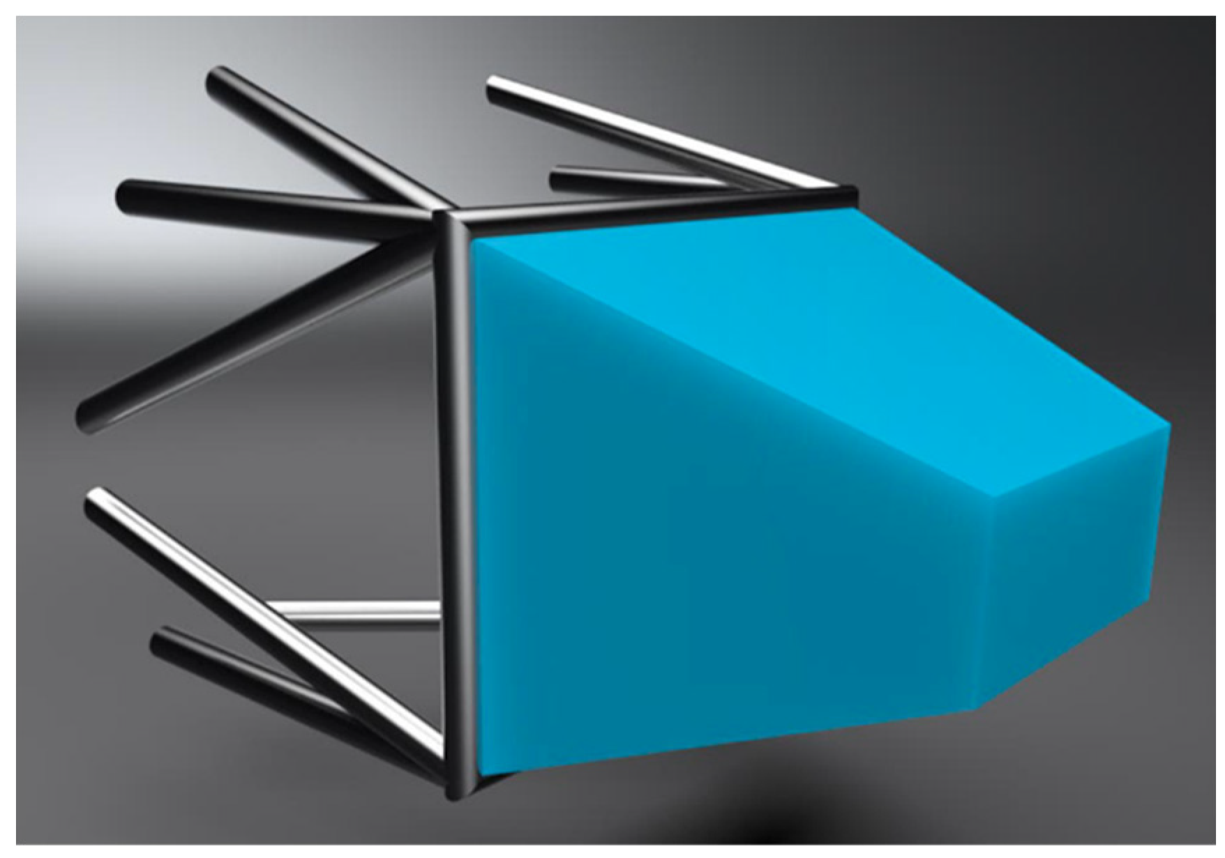
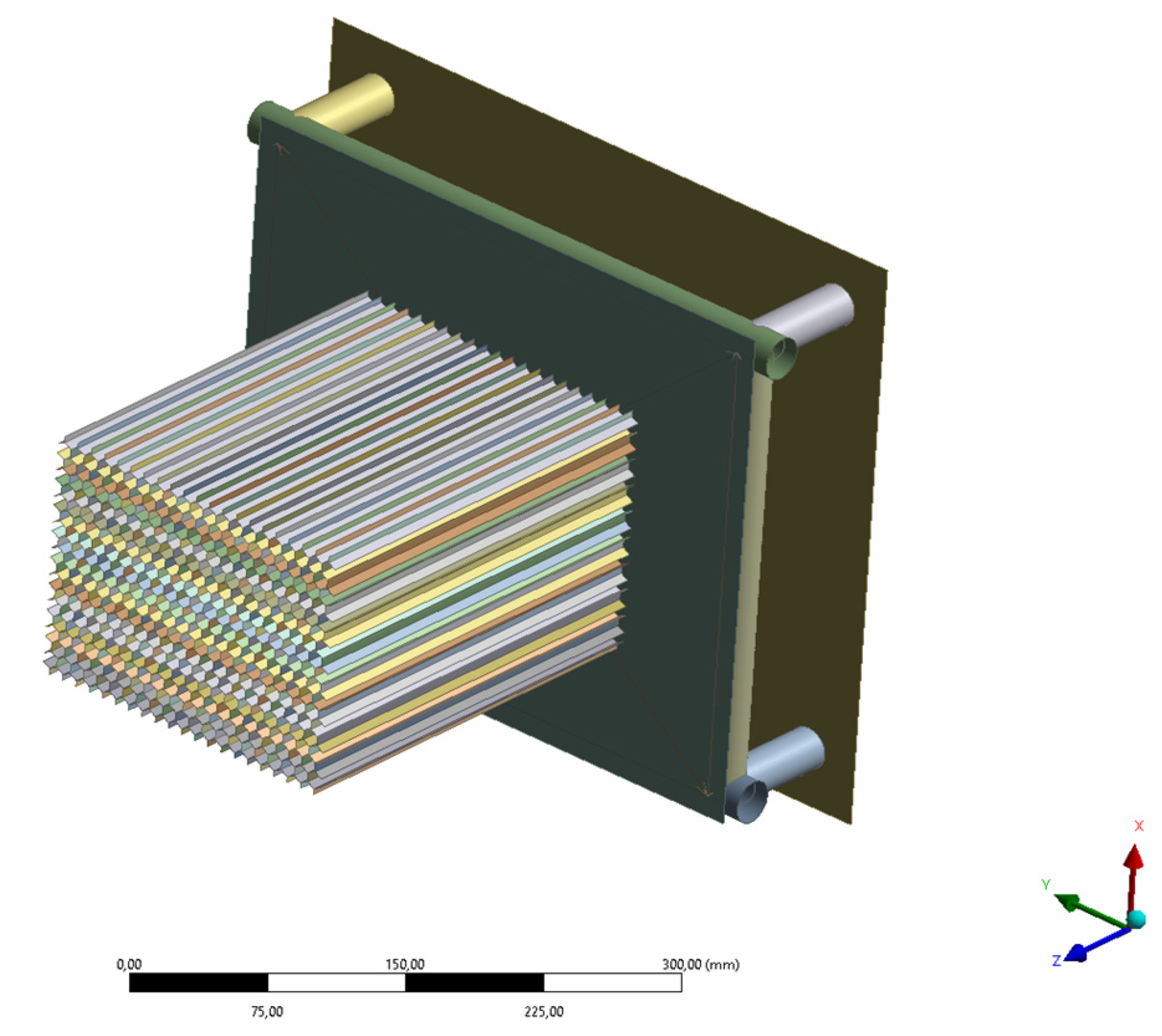
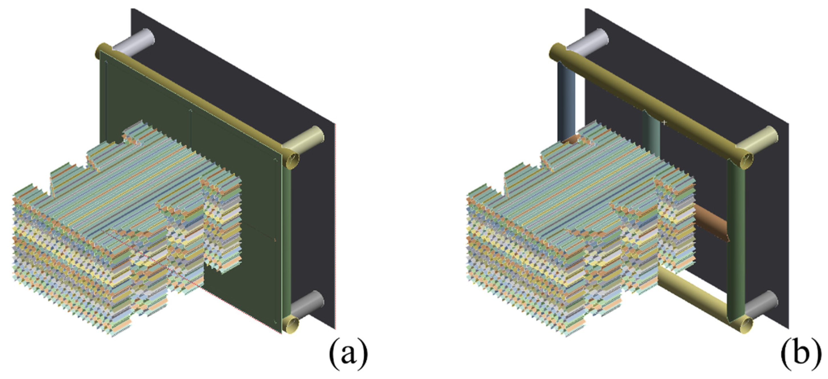
  • Wall: Hidden in Figure 7, which is a rigid plane, normal to the Oz axis, 1 mm away from the rear most surface of the IA.
  • IA: An aluminum honeycomb block dimensioning 200 mm × 150 mm × 250 mm (profile A or B), which is further modified for different variations.
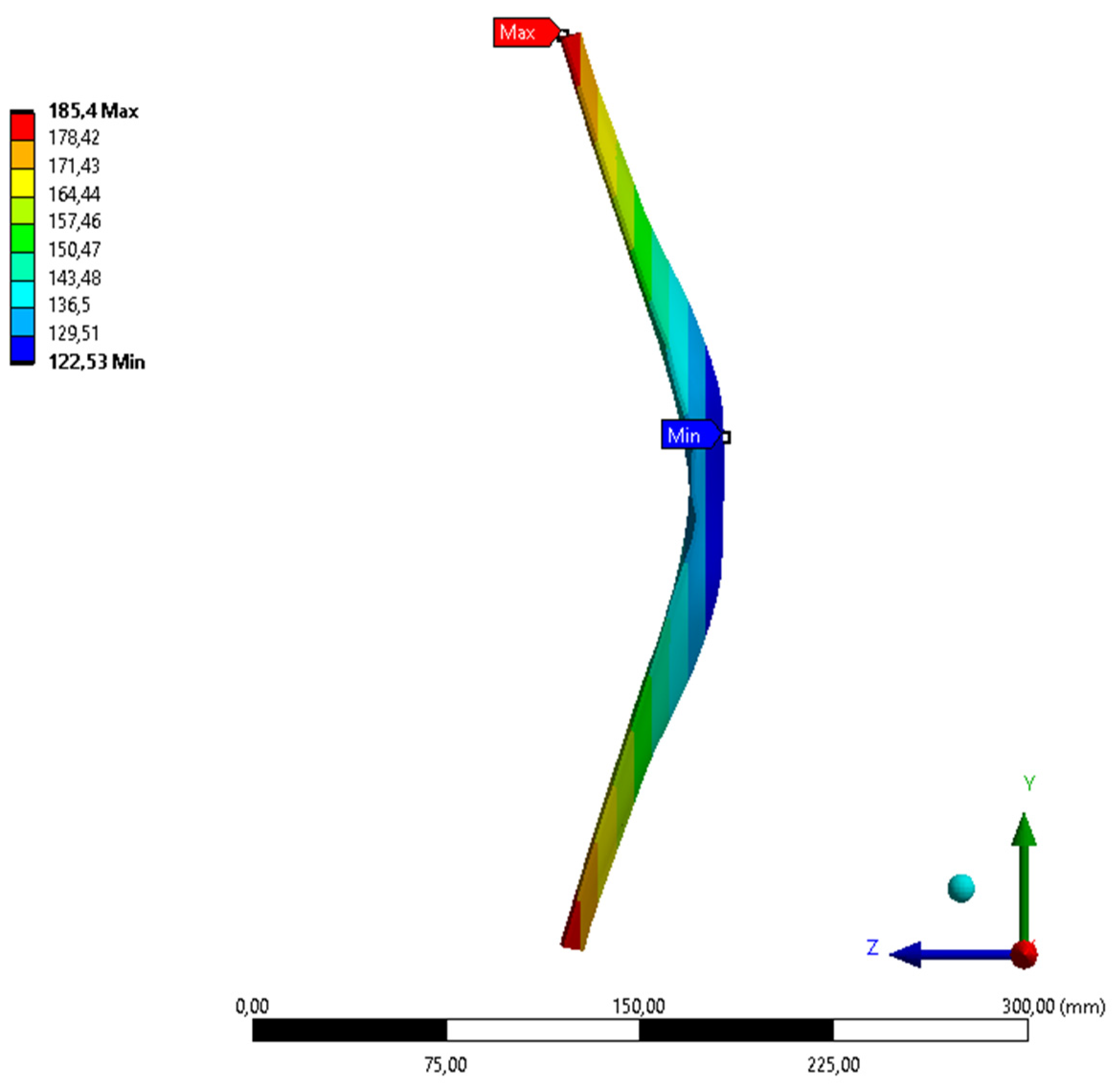
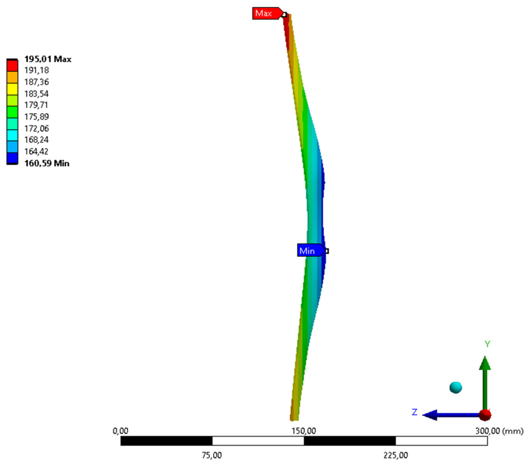
  • AIP: Rectangular steel plate dimensioning 357 mm × 305 mm × 1.5 mm.
  • FB and other tubes: Four round steel tubes forming a rectangle of 307 mm × 255 mm (center-line distances); one X-bracing or one + -bracing; four extra tubes for mounting the FB on the Vehicle plane. All tubes are round 25 mm, thickness of 2 or 4 mm.
  • Vehicle: A rigid plane with an artificial mass of 300 kg.

2.4.2. Constraints

The rigid Wall is fixed in space in six degrees of freedom (DOF) at 1 mm in front of the IA, using Fix Support function. The rest, as a whole, moves at a velocity of 7000 mm·s−1 in the +Oz direction to crash into the rigid Wall. Additionally, we use the Bonding joining function to weld the FB and other tubes, the AIP and the FB. The same function is used to glue the IA to the AIP. Last but not least, the separate honey walls are grouped to form a continuous IA block.

2.4.3. Materials

Readers can refer to the Table 2 and Table 3 below for the Material properties and Material assignment for the simulations.
It is noteworthy that tangent modulus is employed to describe the behavior of materials after being stressed beyond their elastic limits. Values of 1 or 1000 MPa caused no difference to the numerical results as studied by the authors.

2.4.4. Others

Simulation results were shown in True Scale, no magnification. Automatic Mass Scaling was turned on (Yes), for the efficient computational time and to avoid the Error of too large Energy. Elements which experienced higher stress level than their yield limit would be eliminated from the IA assembly during the impact. Moreover, it is worth noting that the acceleration was measured in mm·s−2 then divided by the gravitational acceleration of g = 9.81 mm·s−2 to obtain the g times, providing a perception of weight for the impacts. The deceleration should be on average 20 g’s and at peak 40 g’s because these are the limits that a human body can withstand, [50].

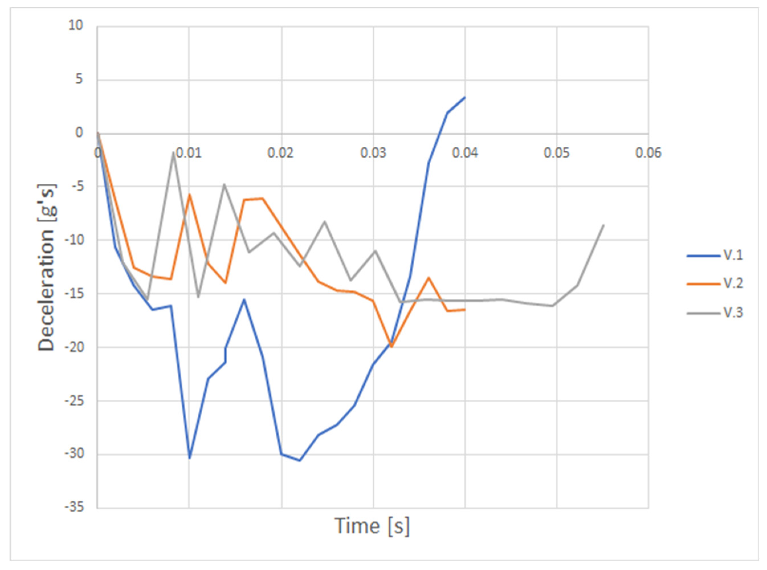
3. Results and Discussions

In Figure 8, there are simulation results of the three versions modified from the basic shape shown in Figure 7. Besides, the deceleration versus time results during the impact are plotted in Figure 9.

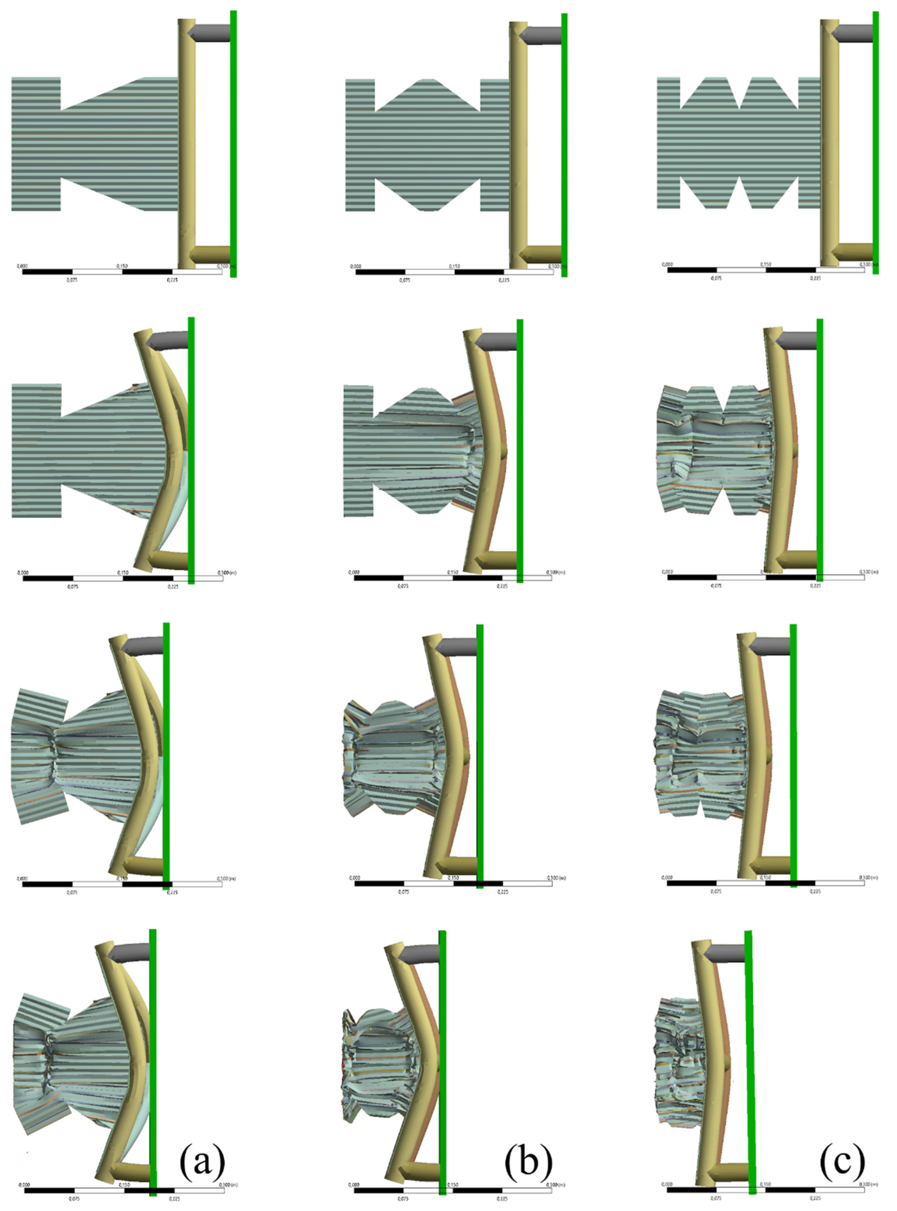
3.1. Version 1 (V.1)

According to the rule [6], because of the relative size of the honeycomb block on the AIP, we must consider adding an X-bracing to enhance the stiffness of the FB. We start with a honeycomb block with profile B. Besides, as an attempt to reduce the peak load, we modify the honeycomb block as in Figure 10 below.
It should be noted that the deceleration versus time also indicates the force versus time load. Regarding Figure 9, the vehicle is fully stopped at 0.038 s and then bounds back. With regard to Figure 7, the assembly moves in +Oz direction to crash into the rigid wall. Thus, from 0 to 0.038 s, the acceleration is negative, deceleration. Later on, the positive acceleration indicates the bound back of the assembly. Additionally, the assembly first experiences a peak load at 0.01 s. The peak load is transferred from the honeycomb cells to the AIP and the FB. If the AIP and the FB survive this peak load, the vehicle will continue to be pushed forward and the peak load will initiate the collapse of the honeycomb block. Then, the honeycomb block will attenuate the kinetic energy from the car crash with its deformation energy.
However, for this version, the AIP and the diagonal tubes of the FB fail under the peak load which is figuratively indicated by the fact that they are squeezed to the rigid vehicle plane at 0.01 s, and henceforth remain intact with the vehicle plane until the end of the simulation.
However, we can notice that the honeycomb block inherits an interesting collapsing pattern. The collapse starts from the shoulder edges which are then folded inward. The kinetic energy is transferred to deformation energy primarily owing to the collapse of the shoulder pattern.
The maximum deformation of the AIP measured from ANSYS as shown in Figure 11 below is 127.1 − 57.82 = 69 mm.
We aim to come up with a design which is strong enough to withstand the peak load indicated by the fact that the AIP deflects less than 25 mm. Thus, this version fails.
Subsequently, for the next versions, we investigate further into decreasing the honeycomb block’s crashworthiness and increasing the FB’s one.

3.2. Version 2 (V.2)

Witnessing that the longer side tubes of the FB experience the most severe deformity, we decide to change the X-bracing to + -bracing to enhance the stiffness of the FB side tubes. In addition, we introduce a so-called double-shoulder pattern on the honeycomb block and change to a smaller honeycomb cell thickness, profile A, to further weaken it as shown in Figure 12 below.
As can be seen in Figure 9, the V.2 curve varies within a smaller range in comparison with V.1. The magnitude of the first peak load, applied within the first 0.008 s period, is reduced significantly. As a result, the AIP deforms less than V.1. However, it still does not meet the 25 mm requirement.
The maximum deformation of the AIP measured from ANSYS as shown in Figure 13 below is 185.4 − 122.5 = 63 mm.

3.3. Version 3 (V.3)

For this version, we further stiffen the FB by increasing the tube thickness of the + -bracing from 2 mm to 4 mm. Additionally, we further pursue the idea of weakening the profile-A-based honeycomb block with a triple-shoulder pattern as shown in Figure 14 below.
With regard to Figure 8, we can observe that the honeycomb block crashes uniformly. Indeed, this proves the correctness of our findings about the relation between different components contributing to the crashworthiness of the IA assembly. In Figure 9, this uniform crash is indicated by the almost constant trend of the V.3 curve starting from 0.033 s. For vehicle crashes, both in simulations and testing, this constant deceleration is desirable because it helps to ensure the safety of the drivers [10].
The maximum deformation of the AIP measured from ANSYS as shown in Figure 15 below is 195.0 − 160.6 = 34.5 mm.

3.4. Comparison Studies

The simulation results are summarized in Table 4 below.
Before commenting on the data in the above table, it is worth noting that the deceleration is only calculated for the whole crashing period (until the vehicle stops) in V.1. For V.2 and V.3, we cannot capture the moment the vehicle stops during the preset time.
With reference to Figure 9, within the duration of 0.04 s, we can see that V.1 is fully stopped and even bounds back. The deceleration on average and at peak during this period meets the rules. However, the AIP deformation does not satisfy the rules.
For V.2, at 0.04 s, the deceleration–time curve does not show any trend of rising or declining. The decelerations on average and at peak during this period meet the rules. However, the AIP deformation does not satisfy the rules. This is the worst simulation among the three.
For V.3, at 0.055 s, the deceleration–time curve shows a monotonic trend of rising to zero floor. The decelerations on average and at peak during this period meet the rules. Even though the AIP deformation does not satisfy the rules, we can conclude that this version is the most promising one.
Owing to the time that was permitted for this project, our study stopped at V.3.

4. Conclusions

This paper presents crash simulations of aluminum honeycomb IA for the Formula Student VSB-TU Ostrava team. The properties of the aluminum honeycomb are studied from theory and numerical simulations. The effect of different components on the crashworthiness is studied by incrementally developed designs. Specifically, to avoid the force (deceleration) peaks, instead of pre-crushing, we introduce cutting with shoulder pattern. This pattern inherits uniform crushing behavior as shown in the simulation results. Ideally, the force (deceleration) versus time curves are flat. However, in our simulations, the first peak load is reduced but cannot be eliminated thoroughly. The shoulder patterns work well as crush initiators that significantly improve the response of the structure from the frontal impact point of view. Possible future works for this would be to re-evaluate the simulation time so that we can capture the moment when the velocity of the vehicle is reduced to zero. Besides, we can evaluate the effect of mesh sizes on the computing time for optimizing the computing resources according to [51]. These two things should be done in the context of better designs according to the findings in this paper.

Author Contributions

Conceptualization, J.S. and J.M.; methodology, Z.P.; formal analysis, P.M.Q. and D.K.; investigation, P.M.Q. and D.K.; writing—original draft preparation: P.M.Q.; writing—review and editing, P.M.Q. and D.K.; supervision, Z.P.; project administration, A.S.; funding acquisition, J.P. All authors have read and agreed to the published version of the manuscript.

Funding

The research was funded in association with project Innovative and additive manufacturing technology—new technological solutions for 3D printing of metals and composite materials, reg. no. CZ.02.1.01/0.0/0.0/17_049/0008407 financed by Structural Funds of the European Union and project.

Acknowledgments

This article has been completed in connection with project Innovative and additive manufacturing technology–new technological solutions for 3D printing of metals and composite materials, reg. no. CZ.02.1.01/0.0/0.0/17_049/0008407 financed by Structural Funds of European Union and project. The authors express their gratitude towards the Formula Student VSB-TU Ostrava for establishing the foundation for this project.

Conflicts of Interest

The authors declare no conflict of interest.

References

  1. Institution of Mechanical Engineers. Available online: https://www.imeche.org/events/formula-student/about-formula-student (accessed on 19 August 2020).
  2. Mesicek, J.; Pagac, M.; Petru, J.; Novak, P.; Hajnys, J.; Kutiova, K. Topological optimization of the formula student bell crank. MM Sci. J. 2019, 2019, 2964–2968. [Google Scholar] [CrossRef]
  3. Kutiová, K.; Měsíček, J.; Krzikalla, D. Experimental examination of adhesive bonded carbon Fibre tube to aluminum alloy AW 7075. Mater. Sci. Forum 2020, 994, 125–132. [Google Scholar] [CrossRef]
  4. Mesicek, J.; Richtar, M.; Petru, J.; Pagac, M.; Kutiova, K. Complex view to racing car upright design and manufacturing. Manuf. Technol. 2018, 18, 449–456. [Google Scholar] [CrossRef]
  5. Hunar, M.; Jancar, L.; Krzikalla, D.; Kaprinay, D.; Srnicek, D. Comprehensive view on racing car upright design and manufacturing. Symmetry 2020, 12, 1020. [Google Scholar] [CrossRef]
  6. Formula Student Rules. 2020. Available online: https://www.formulastudent.de/fileadmin/user_upload/all/2020/rules/FS-Rules_2020_V1.0.pdf (accessed on 19 August 2020).
  7. Albak, E.I.; Solmaz, E.; Kaya, N.; Öztürk, F. Lightweight foam impact attenuator design for formula Sae car. Turk. J. Eng. 2018, 2, 17–21. [Google Scholar] [CrossRef] [Green Version]
  8. Alexander Bilewski. Available online: https://alexbilewski.myportfolio.com/polsl-racing-2016-impact-attenuator (accessed on 19 August 2020).
  9. Farley, G.L. Energy absorption of composite materials. J. Compos. Mater. 1983, 17, 267–279. [Google Scholar] [CrossRef]
  10. Muhammad, A. Energy Absorption Behaviour of Filament Wound Glass and Carbon Epoxies Composite Tubes. Master’s Thesis, Kano University of Science & Technology, Wudil, Nigeria, 2014; pp. 30–37. [Google Scholar] [CrossRef]
  11. Boria, S.; Obradovic, J.; Belingardi, G. On design optimization of a composite impact attenuator under dynamic axial crushing. FME Trans. 2017, 45, 435–440. [Google Scholar] [CrossRef]
  12. Boria, S.; Pettinari, S. Mathematical design of electric vehicle impact attenuators: Metallic vs composite material. Compos. Struct. 2014, 115, 51–59. [Google Scholar] [CrossRef]
  13. Wang, J.; Yang, N.; Zhao, J.; Wang, D.; Wang, Y.; Li, K.; He, Z.; Wang, B. Design and experimental verification of composite impact attenuator for racing vehicles. Compos. Struct. 2016, 141, 39–49. [Google Scholar] [CrossRef]
  14. Belingardi, G.; Obradovic, J. Design of the impact attenuator for a formula student racing car: Numerical simulation of the impact crash test. J. Serb. Soc. Comput. Mech. 2010, 4, 52–65. [Google Scholar]
  15. López-Campos, J.; Baldonedo, J.; Suárez, S.; Segade, A.; Casarejos, E.; Fernández, J. Finite element validation of an energy attenuator for the design of a formula student car. Mathematics 2020, 8, 416. [Google Scholar] [CrossRef] [Green Version]
  16. Rooppakhun, S.; Boonporm, P.; Puangcha-Um, W. Design and analysis of impact attenuator for student formula. SAE Tech. Pap. Ser. 2015, 1. [Google Scholar] [CrossRef]
  17. Maskery, I.; Aboulkhair, N.T.; Aremu, A.; Tuck, C.; Ashcroft, I.; Wildman, R.; Hague, R. A mechanical property evaluation of graded density Al-Si10-Mg lattice structures manufactured by selective laser melting. Mater. Sci. Eng. A 2016, 670, 264–274. [Google Scholar] [CrossRef] [Green Version]
  18. Vrána, R.; Červinek, O.; Maňas, P.; Koutny, D.; Palousek, D. Dynamic loading of lattice structure made by selective laser melting-numerical model with substitution of geometrical imperfections. Materials 2018, 11, 2129. [Google Scholar] [CrossRef] [Green Version]
  19. Vrana, R.; Koutny, D.; Palousek, D. Impact resistance of different types of lattice structures manufactured by slm. MM Sci. J. 2016, 2016, 1579–1585. [Google Scholar] [CrossRef]
  20. Vrána, R.; Vaverka, O.; Červinek, O.; Pantělejev, L.; Hurník, J.; Koutný, D.; Paloušek, D. Heat treatment of the SLM processed lattice structure made of AlSi10Mg and its effect on the impact energy absorption. In Proceedings of the Euro PM2019 Congress & Exhibition, Maastricht, The Netherlands, 13–16 October 2019; pp. 1–6, ISBN 978-1-899072-51-4. [Google Scholar]
  21. Kempen, K.; Thijs, L.; Van Humbeeck, J.; Kruth, J.-P. Mechanical properties of AlSi10Mg produced by selective laser melting. Phys. Procedia 2012, 39, 439–446. [Google Scholar] [CrossRef] [Green Version]
  22. Hasan, R.; Mines, R.A.; Shen, E.; Tsopanos, S.; Cantwell, W.; Brooks, W.; Sutcliffe, C. Comparison of the drop weight impact performance of sandwich panels with aluminium honeycomb and titanium alloy micro lattice cores. Appl. Mech. Mater. 2010, 24, 413–418. [Google Scholar] [CrossRef] [Green Version]
  23. Ullah, I.; Brandt, M.; Feih, S. Failure and energy absorption characteristics of advanced 3D truss core structures. Mater. Des. 2016, 92, 937–948. [Google Scholar] [CrossRef]
  24. Veiga, C.; Davim, J.P.; Loureiro, A.J. Properties and applications of titanium alloys: A brief review. Rev. Adv. Mater. Sci. 2012, 32, 133–148. [Google Scholar]
  25. Hwang, J.-S.; Choi, T.-G.; Lee, N.; Lyu, M.-Y.; Gil Lee, D.; Yang, D.-Y. Development of a bendable pyramidal kagome structure and its structural characteristics. Compos. Struct. 2016, 142, 87–95. [Google Scholar] [CrossRef]
  26. Smith, M.; Guan, Z.; Cantwell, W. Finite element modelling of the compressive response of lattice structures manufactured using the selective laser melting technique. Int. J. Mech. Sci. 2013, 67, 28–41. [Google Scholar] [CrossRef]
  27. Gümrük, R.; Mines, R. Compressive behaviour of stainless steel micro-lattice structures. Int. J. Mech. Sci. 2013, 68, 125–139. [Google Scholar] [CrossRef]
  28. Yu, B.; Chien, K.; Abu Samk, K.; Hibbard, G. A mechanism for energy absorption: Sequential micro-kinking in ceramic reinforced aluminum alloy lattices during out-of-plane compression. Mater. Sci. Eng. A 2018, 716, 11–22. [Google Scholar] [CrossRef]
  29. Wu, Y.; Liu, Q.; Fu, J.; Li, Q.; Hui, D. Dynamic crash responses of bio-inspired aluminum honeycomb sandwich structures with CFRP panels. Compos. Part B: Eng. 2017, 121, 122–133. [Google Scholar] [CrossRef]
  30. Wang, J.; Shi, C.; Yang, N.; Sun, H.; Liu, Y.; Song, B. Strength, stiffness, and panel peeling strength of carbon fiber-reinforced composite sandwich structures with aluminum honeycomb cores for vehicle body. Compos. Struct. 2018, 184, 1189–1196. [Google Scholar] [CrossRef]
  31. Plascore CrushLite™. Available online: https://www.plascore.com/download/datasheets/energy_absorption_documentation/Plascore_CrushLite-Sheet-Metric.pdf (accessed on 19 August 2020).
  32. Fahland, J.; Hoff, C.; Brelin-Fornari, J. Evaluating impact attenuator performance for a formula SAE vehicle. SAE Int. J. Passeng. Cars-Mech. Syst. 2011, 4, 836–847. [Google Scholar] [CrossRef]
  33. Boria, S. Behaviour of an impact attenuator for formula SAE car under dynamic loading. Int. J. Veh. Struct. Syst. 2010, 2. [Google Scholar] [CrossRef]
  34. Vettorello, A.; Campo, G.A.; Goldoni, G.; Giacalone, M. Numerical-experimental correlation of dynamic test of a honeycomb impact attenuator for a formula SAE vehicle. Metals 2020, 10, 652. [Google Scholar] [CrossRef]
  35. Zhang, S.; Chen, W.; Gao, D.; Xiao, L.; Han, L. Experimental study on dynamic compression mechanical properties of aluminum honeycomb structures. Appl. Sci. 2020, 10, 1188. [Google Scholar] [CrossRef] [Green Version]
  36. Chen, Q.; Shi, Q.; Signetti, S.; Sun, F.; Li, Z.; Zhu, F.; He, S.; Pugno, N.M. Plastic collapse of cylindrical shell-plate periodic honeycombs under uniaxial compression: Experimental and numerical analyses. Int. J. Mech. Sci. 2016, 111, 125–133. [Google Scholar] [CrossRef]
  37. Han, B.; Qin, K.; Yu, B.; Wang, B.; Zhang, Q.; Lu, T.J. Honeycomb–corrugation hybrid as a novel sandwich core for significantly enhanced compressive performance. Mater. Des. 2016, 93, 271–282. [Google Scholar] [CrossRef]
  38. Wang, Z.; Liu, J.; Hui, D. Mechanical behaviors of inclined cell honeycomb structure subjected to compression. Compos. Part B: Eng. 2017, 110, 307–314. [Google Scholar] [CrossRef]
  39. Wang, Z.; Liu, J. Mechanical performance of honeycomb filled with circular CFRP tubes. Compos. Part B Eng. 2018, 135, 232–241. [Google Scholar] [CrossRef]
  40. Balaji, G.; Annamalai, K. Crushing response of square aluminium column filled with carbon fibre tubes and aluminium honeycomb. Thin-Walled Struct. 2018, 132, 667–681. [Google Scholar] [CrossRef]
  41. Segala, D.; Cavallaro, P. Numerical investigation of energy absorption mechanisms in unidirectional composites subjected to dynamic loading events. Comput. Mater. Sci. 2014, 81, 303–312. [Google Scholar] [CrossRef]
  42. Segala, D.B.; Cavallaro, P.V. Energy Absorption Mechanisms in Unidirectional Composites Subjected to Dynamic Loading Events. Available online: https://apps.dtic.mil/sti/citations/ADA564440 (accessed on 19 August 2020).
  43. Zhang, Q.; Zhang, J.; Wu, L. Impact and energy absorption of long fiber-reinforced thermoplastic based on two-phase modeling and experiments. Int. J. Impact Eng. 2018, 122, 374–383. [Google Scholar] [CrossRef]
  44. Yu, B.; Deshpande, V.; Fleck, N. Perforation of aluminium alloy-CFRP bilayer plates under quasi-static and impact loading. Int. J. Impact Eng. 2018, 121, 106–118. [Google Scholar] [CrossRef] [Green Version]
  45. HexWebTM. Honeycomb Sandwich Design Technology. Available online: https://www.hexcel.com/user_area/content_media/raw/Honeycomb_Sandwich_Design_Technology.pdf (accessed on 19 August 2020).
  46. Gibson, L.J.; Ashby, M.F. Cellular Solids: Structure and Properties; Cambridge University Press: Cambridge, UK, 1999. [Google Scholar]
  47. PAMG-PA3 5052 Aluminum Honeycomb. Available online: https://www.plascore.com/download/datasheets/honeycomb_data_sheets/PLA_PAMG_PA3_5052.pdf (accessed on 19 August 2020).
  48. HexWebTM. Honeycomb Attributes and Properties. Available online: https://www.hexcel.com/user_area/content_media/raw/HexWebHoneycombAttributesandProperties.pdf (accessed on 19 August 2020).
  49. Ma Quoc, P. Design and Numerical Modeling of Impact Attenuator. Available online: http://hdl.handle.net/10084/129693 (accessed on 19 August 2020).
  50. Kumar, K.V.; Norfleet, W.T. Issues of Human Acceleration Tolerance after Long-Duration Space Flights. Available online: https://ntrs.nasa.gov/citations/19930020462 (accessed on 19 August 2020).
  51. Markopoulos, A.; Hapla, V.; Čermák, M.; Fusek, M. Massively parallel solution of elastoplasticity problems with tens of millions of unknowns using PermonCube and FLLOP packages. Appl. Math. Comput. 2015, 267, 698–710. [Google Scholar] [CrossRef]
Figure 1. Standard IA [8].
Symmetry 12 01647 g001
Figure 2. Workflow diagram of the present paper.
Symmetry 12 01647 g002
Figure 3. Honeycomb terminologies [45].
Symmetry 12 01647 g003
Figure 4. Aluminum honeycomb crush curve [48].
Symmetry 12 01647 g004
Figure 5. Axial elastic buckling of hexagon cells [46].
Symmetry 12 01647 g005
Figure 6. Axial plastic buckling of hexagon cells (a) in general and (b) on one wall, [46].
Symmetry 12 01647 g006
Figure 7. Simulation model, [49].
Symmetry 12 01647 g007
Figure 8. Top view. Three columns from left to right, the deformation shape to time of (a) Version 1 (V.1), (b) Version 2 (V.2), and (c) Version 3 (V.3), respectively [49].
Symmetry 12 01647 g008
Figure 9. The deceleration versus time curves of V.1, V.2, and V.3, [49].
Symmetry 12 01647 g009
Figure 10. Design of V.1 (a) with the AIP, and (b) without the AIP, [49].
Symmetry 12 01647 g010
Figure 11. Deformation shape of AIP in V.1, [49].
Symmetry 12 01647 g011
Figure 12. Design of V.2 (a) with the AIP, and (b) without the AIP, [49].
Symmetry 12 01647 g012
Figure 13. Deformation shape of AIP in V.2, [49].
Symmetry 12 01647 g013
Figure 14. Design of V.3 (a) with the AIP, and (b) without the AIP, [49].
Symmetry 12 01647 g014
Figure 15. Deformation shape of AIP in V.3, [49].
Symmetry 12 01647 g015
Table 1. Honeycomb dimensions.
MaterialDensityCell sizeCell Thickness
profile A3.0 pcf3⁄8 inch0.002 inch
(0.0480 g·cm−3)(9.525 mm)(0.0508 mm)
profile B5.4 pcf3⁄8 inch0.004 inch
(0.0865 g·cm−3)(9.525 mm)(0.1016 mm)
Table 2. Material properties, [49].
Al 5052Structural Steel (SS)Structural Steel Artificial (SSA)Unit
Density 26807850214,000kg·m−3
Young’s modulus70,300200,000200,000MPa
Poisson ratio0.330.30.3-
Yield strength193200200MPa
Tangent modulus 110001000MPa
Table 3. Material assignment, [49].
ComponentMaterialThickness [mm]TypeNote
IAAl 50529.525 × 0.1 (profile B) or 9.525 × 0.05 (profile A)DeformableCell size × Cell thickness. Bond node thickness is double.
AIPSS1.5Deformable-
FB + other tubesSS2.0 or 4.0Deformable-
WallSSA1.0Rigid1 mm away from IA
Vehicle SSA10Rigid-
Table 4. Result summary, [49].
NamePeak Deceleration [g’s]Average Deceleration [g’s]AIP Deformation [mm]Note
V.130.518.069.0X-bracing, 2 mm tubes, profile B
V.219.911.963.0+ -bracing, 2 mm tubes, profile A
V.316.111.834.5+ -bracing, 4 mm tubes, profile A

