Article

Free Convection Heat Transfer and Entropy Generation in an Odd-Shaped Cavity Filled with a Cu-Al2O3 Hybrid Nanofluid

by
Mohammad Ghalambaz
1,2,
Seyed Mohsen Hashem Zadeh
3,
Ali Veismoradi
4,
Mikhail A. Sheremet
5,* and
Ioan Pop
6
1
Metamaterials for Mechanical, Biomechanical and Multiphysical Applications Research Group, Ton Duc Thang University, Ho Chi Minh City 758307, Vietnam
2
Faculty of Applied Sciences, Ton Duc Thang University, Ho Chi Minh City 758307, Vietnam
3
Department of Mechanical Engineering, Shahid Chamran University of Ahvaz, Ahvaz 61355, Iran
4
Chemical Engineering Department, Ferdowsi University, Mashhad 91735, Iran
5
Laboratory on Convective Heat and Mass Transfer, Tomsk State University, 634050 Tomsk, Russia
6
Faculty of Mathematics and Computer Science, Babeş-Bolyai University, 400084 Cluj-Napoca, Romania
*
Author to whom correspondence should be addressed.
Submission received: 13 December 2020 / Revised: 3 January 2021 / Accepted: 6 January 2021 / Published: 12 January 2021
(This article belongs to the Special Issue Recent Advances in Conjugate Heat Transfer)

Abstract

:
The present paper aims to analyze the thermal convective heat transport and generated irreversibility of water-Cu-Al2O3 hybrid nanosuspension in an odd-shaped cavity. The side walls are adiabatic, and the internal and external borders of the enclosure are isothermally kept at high and low temperatures of Th and Tc, respectively. The control equations based on conservation laws are formulated in dimensionless form and worked out employing the Galerkin finite element technique. The outcomes are demonstrated using streamlines, isothermal lines, heatlines, isolines of Bejan number, as well as the rate of generated entropy and the Nusselt number. Impacts of the Rayleigh number, the hybrid nanoparticles concentration (ϕhnf), the volume fraction of the Cu nanoparticles to ϕhnf ratio (ϕr), width ratio (WR) have been surveyed and discussed. The results show that, for all magnitudes of Rayleigh numbers, increasing nanoparticles concentration intensifies the rate of entropy generation. Moreover, for high Rayleigh numbers, increasing WR enhances the rate of heat transport.

1. Introduction

The interest in the field of heat transfer has increased considerably recently. While device performance and heat generation have gone up, the sizes of the components have shrunk. For instance, computer chips that are made today are at least several orders of magnitude smaller in size as compared to the past. Thus, the generated heat per surface area is growing continuously. Thus, novel designs with improved heat transfer capabilities are demanded to cool devices that produce large amounts of heat.
Heat transfer in enclosed geometries with various initial and boundary conditions have been a hot topic in the past few decades. This is because these types of geometries have been utilized extensively in real-life applications, such as the cooling of electronic devices, thermal design of buildings, lubrication and drying applications, furnace and nuclear reactors, biochemical, and food processing. Nonetheless, rectangular and square lid-driven cavities have been studied more because of their simplicity and applicability. As such, a large portion of convective heat transport in cavities’ studies has been devoted to rectangular geometries.
Among all the commonly used approaches to enhance heat transfer efficiency, including the passive and active methods, the dispersion of nano-sized particles of highly conductive material in the base working fluids seems to be both simpler and more promising. Hence, in recent years, many studies have focused on applying nanofluids in heat transfer devices, including solar collectors, electronics, nuclear reactors, food, glass, and others [1,2,3,4,5]. For instance, Abu-Nada and Chamkha [6] investigated the role of Cu nanoparticles, Rayleigh number, and aspect ratio of the cavity in free convection heat transfer of CuO-EG-Water nanoliquid. They found that the aspect ratio of the enclosure considerably impacts the rate of heat transfer. Oztop and Abu-Nada [7] surveyed the free convection heat transfer problem of nanoliquids in rectangular cavities. They [7] revealed that the average Nusselt number enhances as the volume fraction of the nanoparticles increases. Parvin and Chamkha [8] presented a thermal convective motion, energy transport, and entropy production in an odd-shaped chamber. The computational analysis on the influence of thermal convection and solid particle concentration on Nu, total entropy generation, and Be was performed in the chamber saturated with Cu-H2O nanosuspension, which concluded horizontal and vertical parts. Furthermore, the entropy production resulting from energy transference, streamlines, and isotherms is shown for different Ra and particle concentrations.
Hybrid nanoliquids are a new type of nanoliquids. Generally, these types of fluid can be prepared by two separate approaches: (a) dispersion of two (or even more) nano-sized particles to a base fluid, and (b) by suspending the so-called hybrid (also composite) nanoparticles to a host liquid. The efficacy of hybrid nanosuspensions through their chemo-physical characteristics was tested and proved by many numerical and experimental studies. The properties and applicability of hybrid nanosuspensions were extensively reviewed in the literature [9,10,11,12,13,14]. Furthermore, the role of different hybrid nanoparticles on the natural, mixed, and forced convection heat transfer has been discussed in some published research studies on the boundary layer by Suresh et al. [15], Aly and Pop [16], Ismael et al. [17], Waini et al. [18,19], Roslan et al. [20], Khashi’ie et al. [21,22,23], Ali et al. [24], Khan et al. [25] and Liu et al. [26]. For example, according to the experimentations of Suresh et al. [15], by employing Cu–Al2O3 hybrid nanofluid, the rate of heat transfer could be enhanced up to around 13.5%. Ismael et al. [17] numerically surveyed the irreversibility and heat transfer of Cu–Al2O3 hybrid nanofluid in a lid-driven cavity. They reported that using hybrid nanofluids is promising for the improvement of heat transfer and reducing the size of heat transfer devices. Roslan et al. [20] investigated the mixed convection heat transfer of Al2O3-Cu-water hybrid nanofluids in a rectangular cavity. The top lid of the cavity was moving with a constant velocity, inducing a mixed convection flow. The results of Roslan et al. [20], in agreement with the outcomes of Roslan et al. [20], showed that the presence of hybrid nanoparticles improved the heat transfer. Following [20], Ali et al. [24] analyzed the mixed convection of the same hybrid nanofluid for a double lid-driven cavity, where both top and bottom lids were moving. This research also confirmed the heat transfer enhancement of using hybrid nanofluids.
With the above review, it can be clearly observed that the natural convection heat transfer of hybrid nanofluids is an important task that could be promising for reducing the size of heat transfer devices. The literature reviewed above shows that the heat transfer and energy generation of nanosuspensions have been addressed in many recent publications. However, the entropy generation and visualization of heat transfer paths (heat-lines) of hybrid nanofluids, and the shape of enclosures, are the influential aspects that have been overlooked in the literature and will be tackled in the present work.

2. Problem Physics

Free convective heat transport of Cu–H2O hybrid nanoliquid in the region formed between a hot block and its chamber is schematically shown in Figure 1.
The vertical (or horizontal) length of the hot (or cold) surfaces is L (or L—W). The width of the cavity is W and can vary to have different width ratios (W/L). The temperature of the interior walls, shown in red in Figure 1, is isothermally kept constant at Th, and the external walls, depicted in blue, are at the temperature of Tc. The remaining borders are assumed to be adequately insulated. It is assumed that the circulation is steady, incompressible, laminar, and the radiation has no significant effect on the process.

2.1. Governing Equations

Under the above-mentioned assumptions, the control equations for the hybrid nanoliquid, based on conservation laws, are [8,27]:
Continuity Equation:
u x + v y = 0
Momentum Equation:
ρ h n f ( u u x + v u y ) = p x + μ h n f ( 2 u x 2 + 2 u y 2 )
ρ h n f ( u v x + v v y ) = p y + μ h n f ( 2 v x 2 + 2 v y 2 ) + ( ρ β ) h n f g ( T T c )
Energy Equation:
( ρ c ) h n f ( u T x + v T y ) = k h n f ( 2 T x 2 + 2 T y 2 )
where u and v are the velocity components in x and y directions, T is the temperature of the hybrid nanofluid, g is the gravity and p is the pressure. The corresponding boundary conditions are
T = T h at   the   inner   walls T = T c at   the   outer   walls T n = 0 at   the   rest   of   the   surfaces u = v = 0 at   all   solid   surfaces

2.2. Thermophysical Characteristics

In Equations (1)–(4), ρhnf, (ρc)hnf, βhnf and μhnf denote the density, thermal capacitance, heat expansion coefficient and dynamic viscosity of the nanoliquid which could be calculated from the below relations [28]:
μ h n f = μ f ( 1 φ h n f ) 2.5
ρ h n f = ρ A l 2 O 3 φ A l 2 O 3 + ρ C u φ C u + ( 1 φ h n f ) ρ f
k h n f k f = { φ A l 2 O 3 k A l 2 O 3 + φ C u k C u φ h n f + 2 k f + 2 ( φ A l 2 O 3 k A l 2 O 3 + φ C u k C u ) 2 k f φ h n f } { φ A l 2 O 3 k A l 2 O 3 + φ C u k C u φ h n f + 2 k f ( φ A l 2 O 3 k A l 2 O 3 + φ C u k C u ) + k f φ h n f }
( ρ c ) h n f = φ A l 2 O 3 ( ρ c ) A l 2 O 3 + φ C u ( ρ c ) C u + ( 1 φ h n f ) ( ρ c ) f
( ρ β ) h n f = φ A l 2 O 3 ( ρ β ) A l 2 O 3 + φ C u ( ρ β ) C u + ( 1 φ h n f ) ( ρ β ) f
Here, φ h n f = φ A l 2 O 3 + φ C u is the volume fraction of the hybrid nanofluid. Moreover, the subscripts f, Cu, and Al2O3 refer to the base fluid, Cu, and Al2O3 nanoparticles’ properties, respectively. The physical characteristics of the hybrid nano-sized particles and water (as the host fluid) are gathered in Table 1.

2.3. Non-Dimensional Form of the Governing Equations

Equations (1)–(4) can be non-dimensionalized by introducing the below parameters:
X = x L , Y = y L , U = u L ν f , V = v L ν f , P = p L 2 ρ f ν f 2 , θ = T T c T h T c
Substituting Equation (7) into Equations (1)–(4), results in the next equations
U   X + V   Y = 0
ρ h n f ρ f ( U U X + V U Y ) = P X + μ h n f μ f ( 2 U X 2 + 2 U Y 2 )
ρ h n f ρ f ( U V X + V V Y ) = P Y + μ h n f μ f ( 2 V X 2 + 2 V Y 2 ) + R a P r ( ρ β ) h n f ( ρ β ) f θ  
( ρ c ) h n f ( ρ c ) f ( U θ X + V θ Y ) = k h n f k f ( 2 θ X 2 + 2 θ Y 2 )
where Rayleigh and Prandtl numbers are defined as
R a = ρ g β ( T h T c ) L 3 α f ν f P r = C p μ f k f
The boundary conditions (5) in non-dimensional form become
θ = 1 at   the   inner   walls θ = 0 at   the   outer   walls θ N = 0 at   the   rest   of   the   surfaces U = V = 0 at   all   solid   surfaces

2.4. Rate of Heat Transfer

The parameter of interest in this research is the rate of energy transference from the hot border, which can be quantified by the average Nusselt number Nuavg as:
N u a v g = 1 1 W R k h n f k f { Y = 0 Y = 1 W R θ X | X = 1 W R d Y + X = 0 X = 1 W R θ Y | Y = 1 W R d X }

3. Entropy Generation

The strength of generated entropy is expressed as:
s g e n = k h n f T 0 2 [ ( T x ) 2 + ( T y ) 2 ] + μ h n f T 0 [ 2 ( u x ) 2 + 2 ( v y ) 2 + ( u y + v x ) ]
The first term in the above equation is the energy transference component of entropy production. The second one indicates that the portion of generated entropy caused by friction of the hybrid nanofluid. The generated entropy could be transformed into the non-dimensional form using the below parameters [30,31]:
S = s T 0 2 L 2 k f ( T h T c )
Equation (15) in the non-dimensional form reads as:
S g e n = S t h + S v i s c o u s
where
S t h = k h n f k f [ ( θ X ) 2 + ( θ Y ) 2 ]
S v i s c o u s = χ μ h n f μ f [ 2 ( U X ) 2 + 2 ( V Y ) 2 + ( U X + V Y ) ]
Here χ is called the irreversibility function and can be defined as:
χ = T 0 μ f k f [ L ν f ( T h T c ) ] 2
The ratio of generated entropy induced by energy transference to the total entropy production is called the Bejan number, which is
B e = S t h S g e n
It is apparent that for Be > 0.5 (Be < 0.5), the irreversibility of the energy transference (fluid friction) governs the total entropy production.

4. Heat Function

The x- and y-derivatives of the heat function equal the energy flux components (j,x, j,y) and for the hybrid nanofluid read as [32]:
j x = h y = ( ρ c ) h n f u ( T T c ) k h n f T x
j y = h x = ( ρ c ) h n f v ( T T c ) k h n f T y
Using the non-dimensional heat function as H = h [ α f ( T h T c ) ] , the dimensionless form of the above equations is obtained as:
J X = H Y = ( ρ c ) h n f ( ρ c ) f U θ k h n f k f θ X
J Y = H X = ( ρ c ) h n f ( ρ c ) f V θ k h n f k f θ Y
With a cross derivation, the dimensionless presentation of the heat function could be calculated as the following:
2 H X 2 + 2 H Y 2 = ( ρ c ) h n f ( ρ c ) f { ( V θ ) X ( U θ ) Y }
The boundary conditions for the above equation can be obtained by integrating over the Equations (23) or (24) and imposing the no-slip condition (U = V = 0). In addition, the heat lines on the bottom wall can be arbitrary set to zero [32]:
on the bottom wall:
H ( 1 W R 0 1 , 0 ) = 0
on the inner walls:
H ( 1 W R , 0 Y 1 W R ) = k h n f k f 0 Y θ X d Y   and H ( 0 X 1 W R , 1 W R ) = k h n f k f 0 X θ Y d X k h n f k f 0 1 W R θ X | 1 W R , 0 Y 1 W R d Y
on the outer walls:
H ( 1 , 0 Y 1 ) = k h n f k f 0 Y θ X d Y   and   H ( 0 X 1 , 1 ) = k h n f k f 0 X θ Y d X k h n f k f 0 1 θ X | 1 , 0 Y 1 d Y
on the right adiabatic wall:
H ( 0 , 1 W R Y 1 ) = N u a v g = k h n f k f 0 1 W R θ Y | 0 X 1 W R , 1 W R d X k h n f k f 0 1 W R θ X | 1 W R , 0 Y 1 W R d Y
The employed numerical method, details of the grid check and validations are discussed in the Appendix A and Appendix B.

5. Results and Discussion

In this section, different parameters including Rayleigh number (Ra = 103, 104 and 105), width ratio (WR = W/L = 0.2, 0.3 and 0.4), the concentration of the hybrid nanoparticles (0.0 ≤ ϕhnf ≤ 0.05) and the concentration of Cu to ϕhnf ratio (0.0 ≤ ϕr = ϕCu/ϕhnf ≤ 1.0) have been surveyed and discussed. Moreover, the Prandtl number Pr = 6.2 is considered to be constant in all simulations.
Figure 2 shows the isotherms, heat lines, and streamlines in the cavity filled with hybrid nanosuspension for different Ra and WR values. Figure 2a represents the isotherms, which as seen, the isotherms are layered in the horizontal direction at Ra = 103. The layered arrangements of the isotherms confirm that conduction energy transference is the dominant mode of heat transport in the chamber. It should be noted that the isotherms signify the strength of the conduction heat transfer; for instance, it can be observed from Figure 2 that the conduction energy transference has larger values near the walls (especially the hot walls). Conversely, the heat lines at Ra = 103 and WR = 0.2 show the perpendicular lines toward isotherms, and heat lines in this figure represent the routes of the energy transference from the hot border to the cold border with the conduction mechanism. Furthermore, the first row of Figure 2c demonstrates a vortex zone in the vertical part of the chamber, which represents a slight fluid velocity in this region. By increasing the WR from 0.2 to 0.3 at the same Ra (second row), the isotherms tend to separate as a result of conduction energy transference reduction. In this new state, the maximum value of the heat line is reduced from 9 to 5.5, and this reduction shows the lower energy transport strength in the cavity. Therefore, it can be concluded that the rate of energy transport from the hot border to the cold border decreases if the wall width increases when the conduction is the dominant phenomenon.
The uniformity of isotherms is gone when the Ra number is increased to 105 at the same WR = 0.3 (third row), especially in the horizontal zone of the chamber. It depicts that the conduction energy transference is mainly restricted to the walls, and Ra increment leads to increasing buoyancy force. Moreover, the streamlines show different vortices at Ra = 105 and WR = 0.3, and these vortices are started to evolve in a horizontal direction, and the routes of heat transfer are mainly similar to streamlines. Therefore, it can be concluded; the free convective energy transference now is the dominant mode in the cavity. In the last line of Figure 2, the effect of WR is depicted at the high value of Ra. By increasing the WR from 0.3 to 0.4 at the Ra = 105, the conduction effect on heat transfer is weakened, even in the cavity’s vertical part. Furthermore, the stronger vortexes and more extensive heat lines distribution, especially in the horizontal part, show the dominance convection heat transfer, which is boosted by increasing the wall width. It can be found from Figure 2 that the maximum value of the heat lines is raised in the high Ra when the wall width is increased. Therefore, increasing wall width has a direct influence on energy transference at the high Ra. Figure 2d shows the isentropic lines as the Be number is changed in the range between 0 and 1. It can be observed from the figures that the lines, with larger values, are close to walls. It shows in these areas the thermal entropy has mainly the same values as total entropy. In addition, some lines with lower values of Be are emerged in the middle of vertical cavity by increasing Ra and WR that show the effect of viscous entropy in these areas. Furthermore, these lines extend in horizontal part when the convective energy transport is the dominant mode in the chamber. Figure 3 shows the alteration of average Nu values against the total amount of nanoparticle volume fractions, with an equal proportion of Cu and Al2O3 in the water-based fluid. It can be obtained from Figure 3a, that the Nuavg has a more considerable value in the higher Ra as a result of natural convection increment, which was discussed in Figure 2. On the other hand, Figure 3a shows that the Nuavg rises when a higher concentration of solid particles presents in the medium. The investigated nanoparticles in this research have a high heat transfer conduction coefficient, and the presence of these materials can enhance the conduction phenomena. For this reason, the same slops are observed in Figure 3a, and this represents that the nanoparticles have the same and constant effect in different Ra values. Figure 3b shows that the Be number goes down when the Ra number is increased. For high Ra, the energy transport is enhanced. Therefore, the generated entropy due to energy transference increases, but it can be found from Figure 3b that the generated entropy caused by friction of the hybrid nanofluid has a higher value increment compared to Sth that leads to Be number reduction. However, nanoparticle volume fractions have no influence on the Be number in any values of the Ra (see Figure 3b). After increasing the nanoparticle volume fractions, heat transfer entropy and overall entropy both increased, so Be remained almost constant.
Figure 4 and Figure 5 demonstrate the influence of Cu nanoparticles concentration (in the constant value of ϕr) on the Nuavg and Be numbers in different values of wall width. Figure 4a reveals that the percentage of Cu nanoparticle volume fractions has no considerable effect on the Nuavg. Both Cu and Al2O3 have a similar influence on hybrid nanofluid at Ra = 103. It can be seen from this Figure that the Nuavg reduces considerably when the wall width is increased from 0.2 to 0.4. As previously described at Ra = 103, the conduction energy transference is the dominant regime; therefore, it is evident that the Nuavg decreases according to the Fourier law when the WR increases. This reduction in heat transfer rate leads to entropy decrement, generated by heat transfer, and the Be reduction in Figure 4b is caused by this Sth alterations. Similar to the Nuavg, the percentage of the Cu nanoparticle volume fractions has no considerable effect on Be number, because it does not affect the rate of energy transference at the low Ra; therefore, no entropy is generated by heat transfer and nanofluid frictions; then, Be remains constant at different values of ϕr.
Figure 5a shows that increasing the Cu particles in the hybrid nanofluid has a positive influence on energy transference at Ra = 105, in opposite results, as obtained from Figure 4a. This phenomenon can be attributed to the larger conduction heat transfer coefficient of Cu compared to Al2O3 nanoparticles. By increasing the wall width from 0.2 to 0.3, Nuavg is increased, as shown in Figure 5a. At WR = 0.3, the nanofluid can be circulated more easily in the cavity as a result of buoyancy force at Ra = 105. However, energy transference strength decreases considerably when WR increases to 0.4. Figure 5b shows similar results in Figure 4b, but for different reasons. The generated entropy caused by frictions increases when the wall width changes from 0.2 to 0.3 because of the nanofluid movement in the cavity. As for the previous results, Be number more depends on Sviscous than Sth at high Ra numbers. Therefore, a considerable reduction can be observed on Be number in Figure 5b when WR reaches 0.3. However, by increasing WR to 0.4, the convection effect is decreased (see Figure 5a); therefore, the nanofluid velocity decreases that leads to entropy reduction (Sviscous). In this state, the Sviscous tends to Sth value, and because of this, the Be does not change noticeably at WR = 0.4 compared to WR = 0.3. Figure 5b shows that the Cu nanoparticle volume fractions in hybrid nanofluid have no substantial effect on Be number as a result of convection mechanisms dominance at high Ra numbers. However, Figure 5b shows that Be slightly decreases with ϕr increment at WR = 0.2. These slight changes can be attributed to Cu density that has a larger value compared to Al2O3. The greater density at high Ra with a narrow wall width leads to increase entropy caused by friction factors and decrease Be number.
Figure 6 shows the influence of the Ra and the hybrid nanoparticles’ concentration on the averaged of produced entropy. As previously mentioned, by increasing the Ra number, the buoyancy force intensifies, and hence, the average velocity and the rate of heat transfer in the enclosure increase (See Equations (22) and (23)). As a result, the velocity and temperature gradient are enhanced, and the generated entropy increases. As can be seen from Figure 6a,b, increasing the Rayleigh number has a considerable impact on both components of the produced entropy. It is evident that for low Rayleigh numbers, the friction share of entropy is almost feeble and the entropy generation is mainly controlled by the heat transfer mechanism. However, in high Rayleigh numbers, Sviscous overtakes its counterpart, Sth and the entropy generation induced by the friction of the hybrid nanofluid completely prevails. On the other hand, increasing the volume fraction of the hybrid nanoparticles, according to Equations (6) and (8) leads to the increment of the thermal conductivity and also the viscosity of the suspension. Hence, it slightly enhances the Sth (See Equation (22)) and Sviscous (See Equation (23)). Finally, Figure 6c represents the final result that the volume fraction of the hybrid nanoparticles, as well as the Ra number, have a direct influence on the total generated entropy in the cavity; however, the impact of the Rayleigh number (buoyancy force) is more substantial than the ϕhnf.

6. Conclusions

The thermo-gravitational convection of water-Cu-Al2O3 in an enclosed cavity was investigated. The enclosed cavity concluded two vertical and horizontal parts, and the heat was transferred from the left vertical border and bottom horizontal border toward other directions. The Cu and Al2O3 nanoparticles were chosen as composite nanoparticles. Then, the different volume fractions of hybrid nanoparticles and their proportion were investigated on the energy transference. Furthermore, the effect of Ra and wall width and their relationship with nanoparticle volume fractions were studied as two other important factors, which affect the energy transference and generated entropy in the chamber. The conclusions are:
-
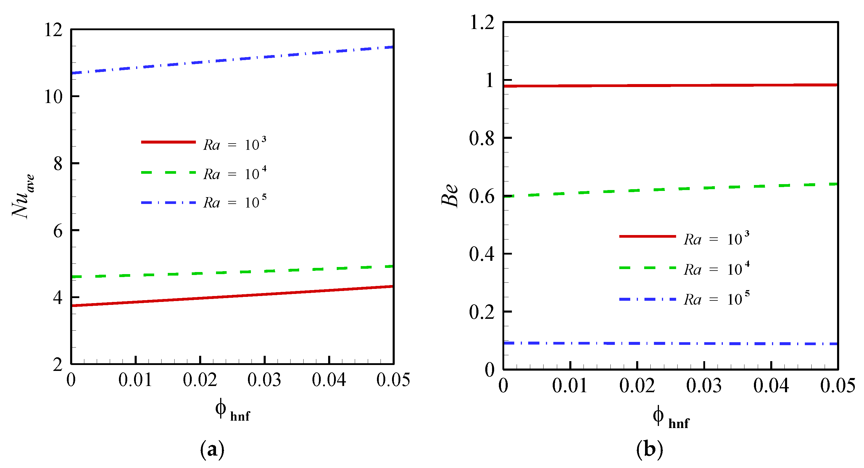
Hybrid nanoparticles enhanced energy transport when the conduction mechanism was dominant. Conversely, they had no significant influence on convective transport;
-
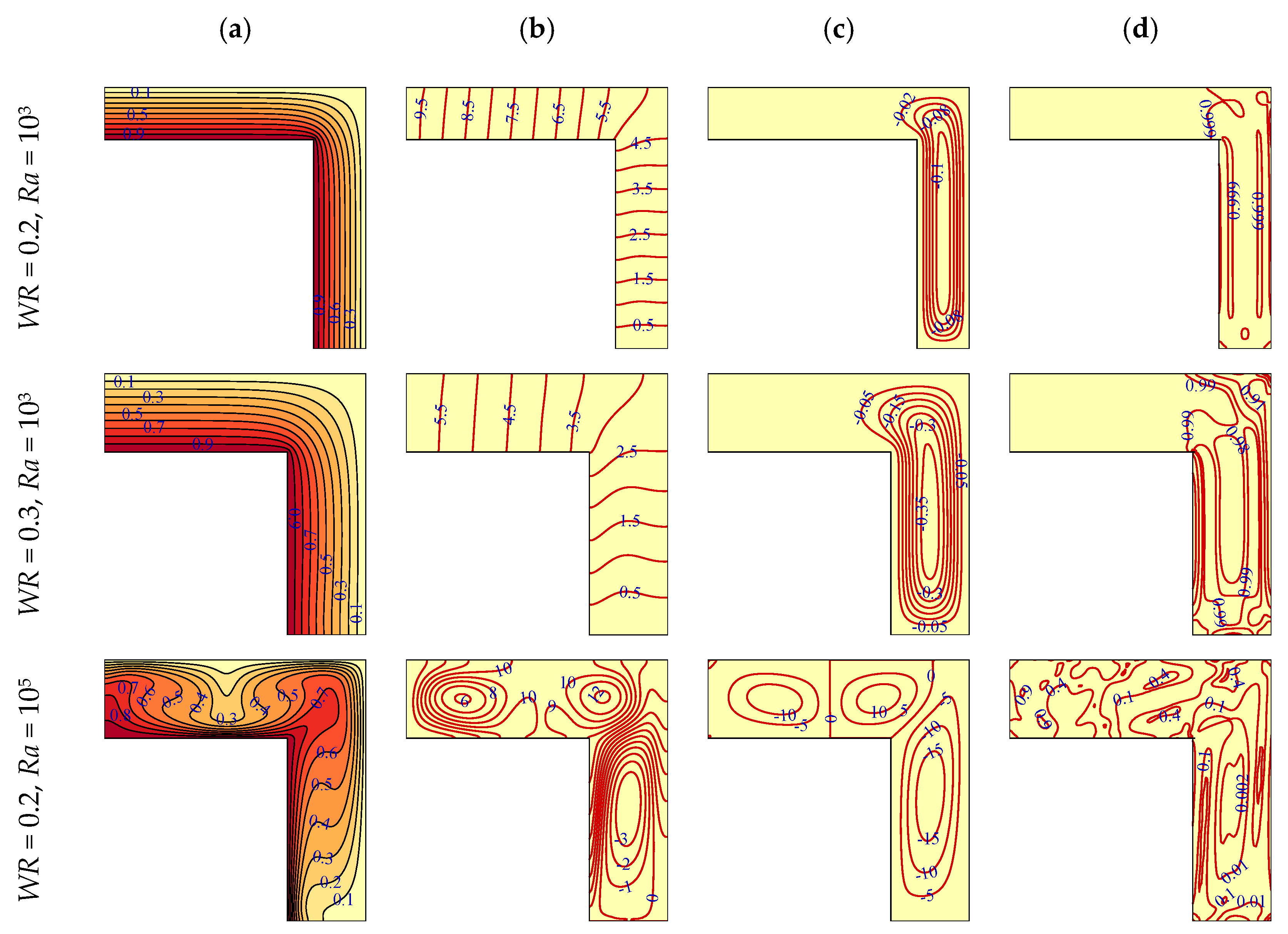
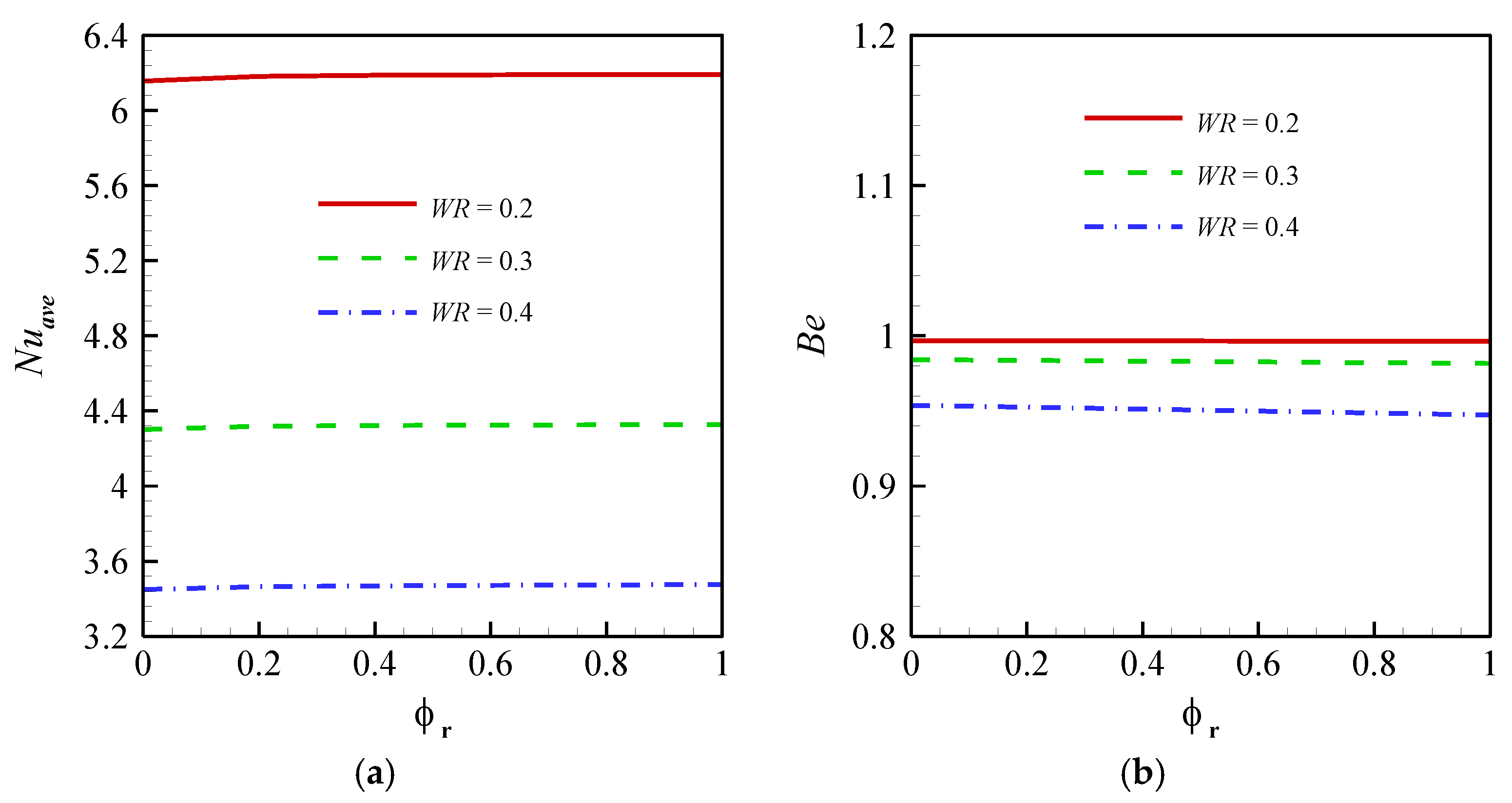
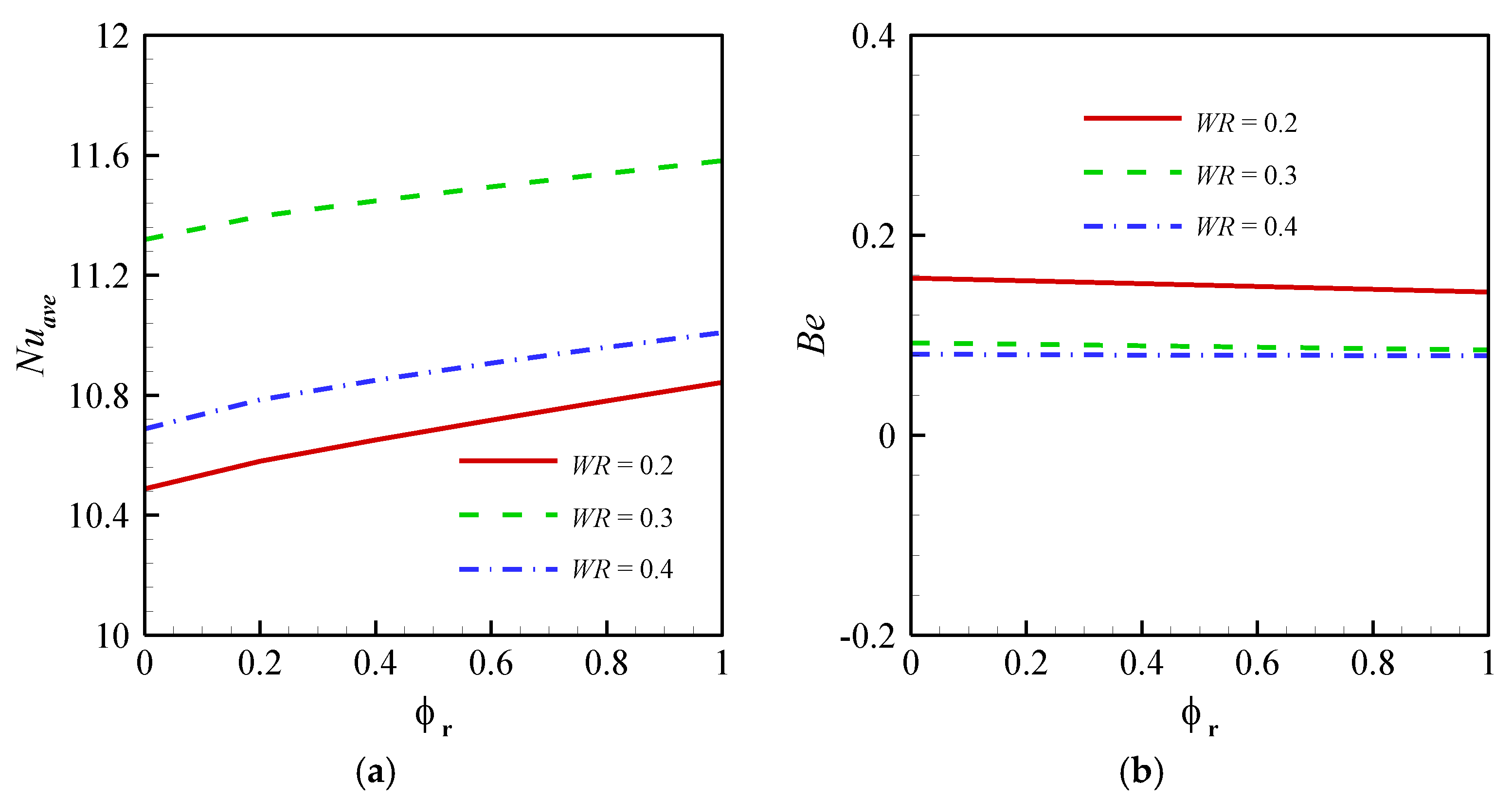
The wall-width ratio (WR) is a parameter that can have a different influence on the energy transference rate in different conditions. Increasing the wall width led to a reduction of the energy transference rate at low Ra (103) owing to the dominant conduction heat transfer mechanism;
-
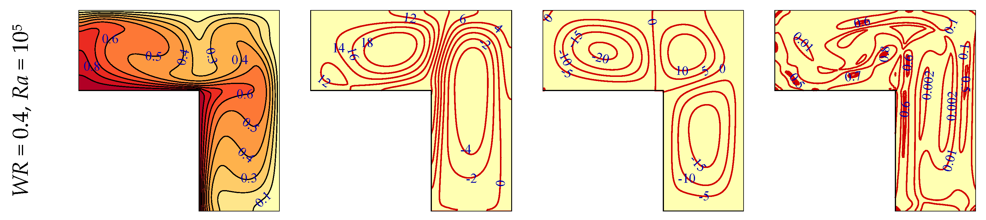
WR had a positive influence on energy transference at high Ra (105) when WR was increased from 0.2 to 0.3. However, a further increase of wall width reduced the heat transfer in the cavity when WR > 0.4, and therefore, an optimum wall width can enhance the heat transfer at high Ra;
-
At Ra = 103, the nanoparticles of Cu and Al2O3 had a similar effect on nanofluid in the range of ϕhnf = 0–0.05, and they enhanced the strength of energy transference to be the same as each other. Conversely, Cu nanoparticles had a stronger impact on heat transfer compared to Al2O3 in convection heat transfer at Ra = 105;
-
Ra and ϕhnf both could enhance generated thermal and viscous entropy, however, Ra had a more intensive influence on generated entropy in the cavity.

Author Contributions

Conceptualization, M.G., S.M.H.Z., A.V., I.P., M.A.S.; methodology, M.G., S.M.H.Z., A.V., I.P., M.A.S.; software, M.G.; validation, M.G.; investigation, M.G., S.M.H.Z., A.V., I.P., M.A.S.; writing—original draft preparation, M.G., S.M.H.Z., A.V., I.P., M.A.S.; writing—review and editing, M.G., S.M.H.Z., A.V., I.P., M.A.S. All authors have read and agreed to the published version of the manuscript.

Funding

This research received no external funding.

Institutional Review Board Statement

Not applicable.

Informed Consent Statement

Not applicable.

Data Availability Statement

Data will be available on request.

Conflicts of Interest

The authors declare no conflict of interest.

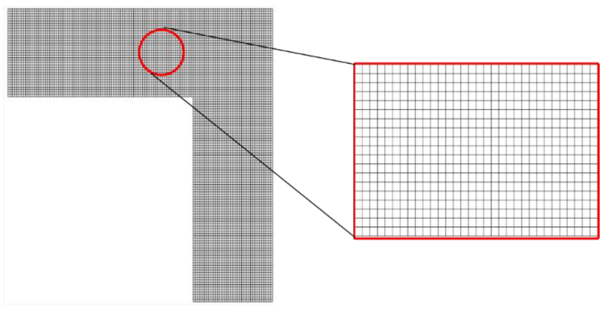
Appendix A. Numerical Approach and Grid Check

The set of non-linear, coupled, and non-dimensional equations discussed above, has been worked out with the Galerkin finite element technique. The method has been well explained in [33]. To replace the pressure terms in the equation of momentum, the penalty parameter is defined as [33,34]:
P = χ ( U X + V Y )
The mass conservation equation will be satisfied automatically when χ is adequately high. By replacing the pressure terms with the above-defined penalty parameter, the momentum equations read:
ρ h n f ρ f ( U U X + V U Y ) = χ X ( U X + V Y ) + μ h n f μ f ( 2 U X 2 + 2 U Y 2 )  
ρ h n f ρ f ( U V X + V V Y ) = χ Y ( U X + V Y ) + μ h n f μ f ( 2 V X 2 + 2 V Y 2 ) + R a P r ( ρ β ) h n f ( ρ β ) f θ
A basis function ( ζ k | k = 1 N ) is used to expand all the existing variables (U, V, θ) within the computational domain:
U k = 1 N U k ζ k ( X , Y ) ,   V k = 1 N V k ζ k ( X , Y ) ,   θ k = 1 N θ k ζ k ( X , Y )
By applying the Galerkin finite element technique, the following set of residual equations will be received for the inner nodes:
R i 1 = ρ h n f ρ f k = 1 N U k Ω [ ( k = 1 N U k ζ k ) ζ k X + ( k = 1 N V k ζ k ) ζ k Y ] ζ i d X d Y + χ k = 1 N U k Ω ζ i X ζ k X d X d Y + χ k = 1 N V k Ω ζ i X ζ k Y d X d Y + μ h n f μ f k = 1 N U k Ω [ ζ i X ζ k X + ζ i Y ζ k Y ] d X d Y
R i 2 = ρ h n f ρ f k = 1 N V k Ω [ ( k = 1 N U k ζ k ) ζ k X + ( k = 1 N V k ζ k ) ζ k Y ] ζ i d X d Y + χ k = 1 N U k Ω ζ i Y ζ k X d X d Y + χ k = 1 N V k Ω ζ i Y ζ k Y d X d Y + μ h n f μ f k = 1 N V k Ω [ ζ i X ζ k X + ζ i Y ζ k Y ] d X d Y + R a P r ( ρ β ) h n f ( ρ β ) f Ω k = 1 N θ k ζ k ( X , Y )
R i 3 = ( ρ c ) h n f ( ρ c ) f k = 1 N θ k Ω [ ( k = 1 N U k ζ k ) ζ k X + ( k = 1 N V k ζ k ) ζ k Y ] ζ i d X d Y + k h n f k f k = 1 N θ k Ω [ ζ i X ζ k X + ζ i Y ζ k Y ] d X d Y
It should be noted that as the solutions of heat function and stream function equations could be obtained from post-processing, there is no need to solve these (and evaluate their residual equations) along with the other equations. Moreover, the process stops iterating when ( R i 1 ) 2 + ( R i 2 ) 2 + ( R i 3 ) 2 10 6 is reached.
As presented in Table A1, the average Nu and the total generated entropy obtained by five different grid densities are compared to ensure that the outcomes are grid-independent. Structured grids with equal length and height (Δx = Δy) are used for grid check. The error percentage for Nuavg and the total generated entropy has been obtained as:
E r r N u S g e n = 100 × | ( N u S g e n ) n ( N u S g e n ) n 1 ( N u S g e n ) n 1 |
It can be seen that the results of the employed case No. 3 with 7344 (Δx = Δy = 1.0/120) have admissible accuracy and hence, has been employed in all of the simulations. In addition, a view of the employed gird (case 3) is depicted in Figure A1.
Table A1. Grid check for Nuavg and Sgen (Ra = 105, Pr = 6.2, ϕhnf = 0.05, WR = 0.3, ϕr = 0.5).
Case Study (n)No. of ElementsNuavgErrNu (%)SgenErrSgen (%)
1326411.025593.70
2 510011.0220.027596.680.499
3734411.0200.018598.330.276
4999611.0190.009599.330.167
513,05611.0190.001599.980.108
Figure A1. The utilized grid with 7344 elements.
Symmetry 13 00122 g0a1

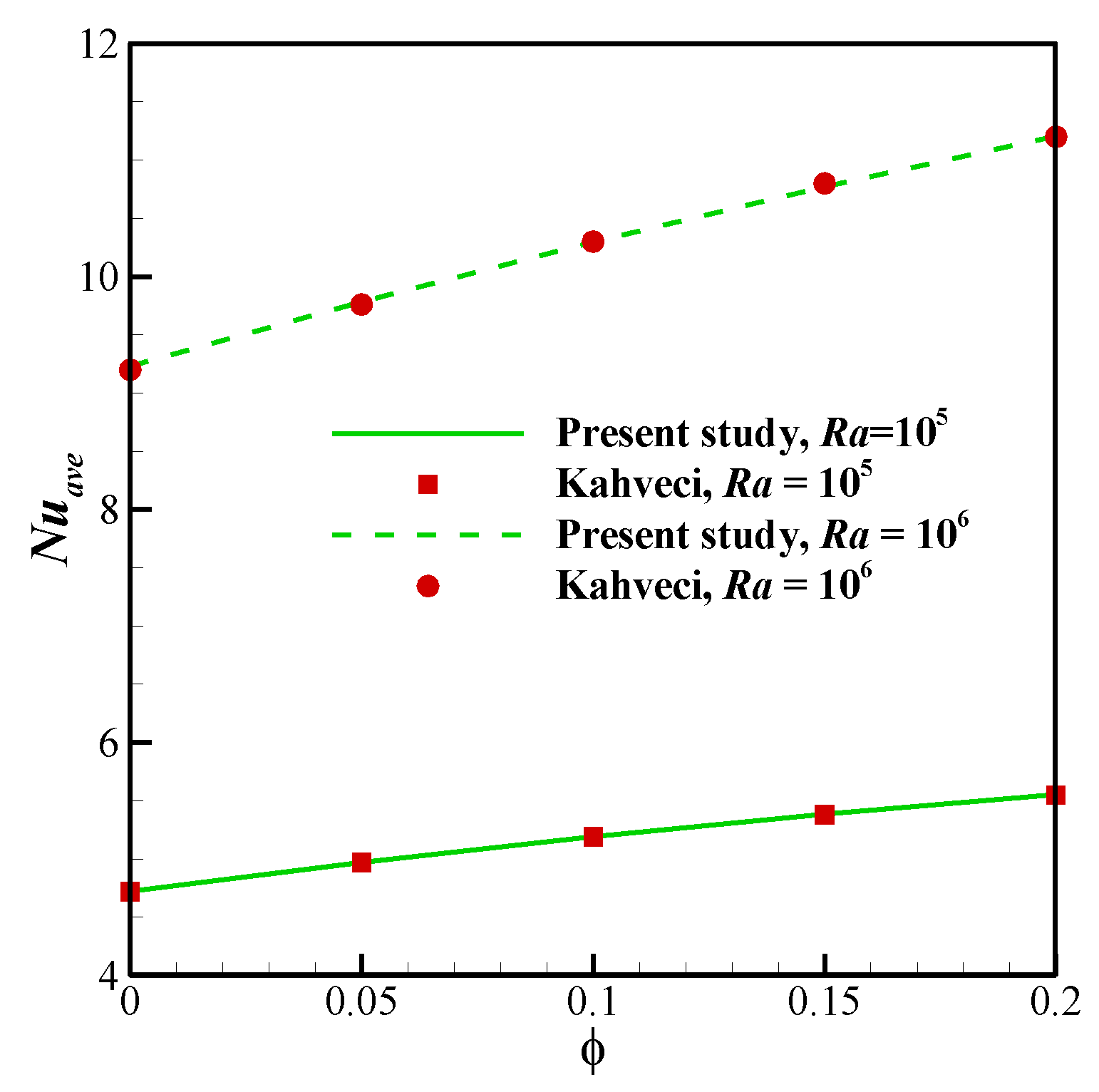
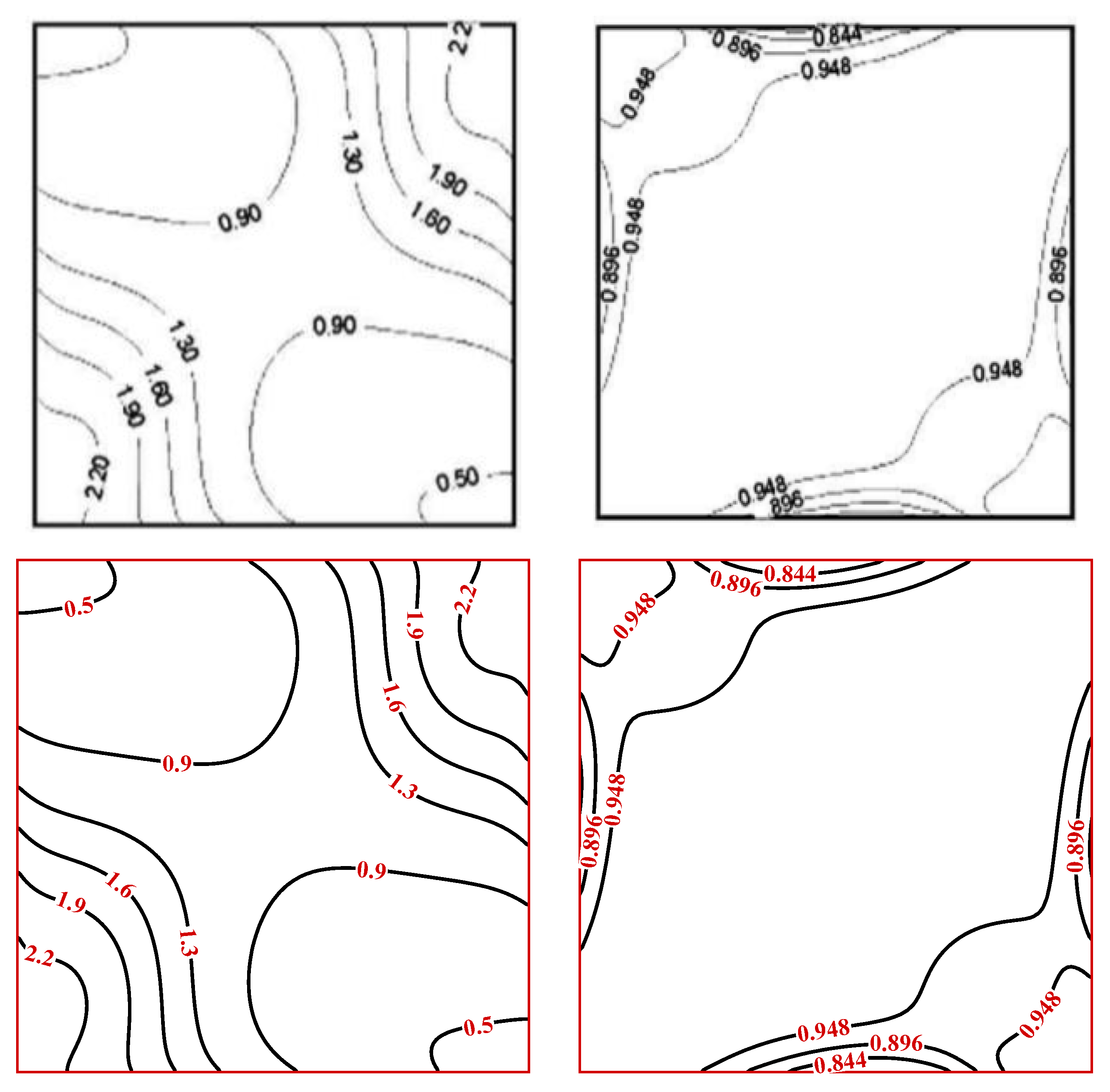
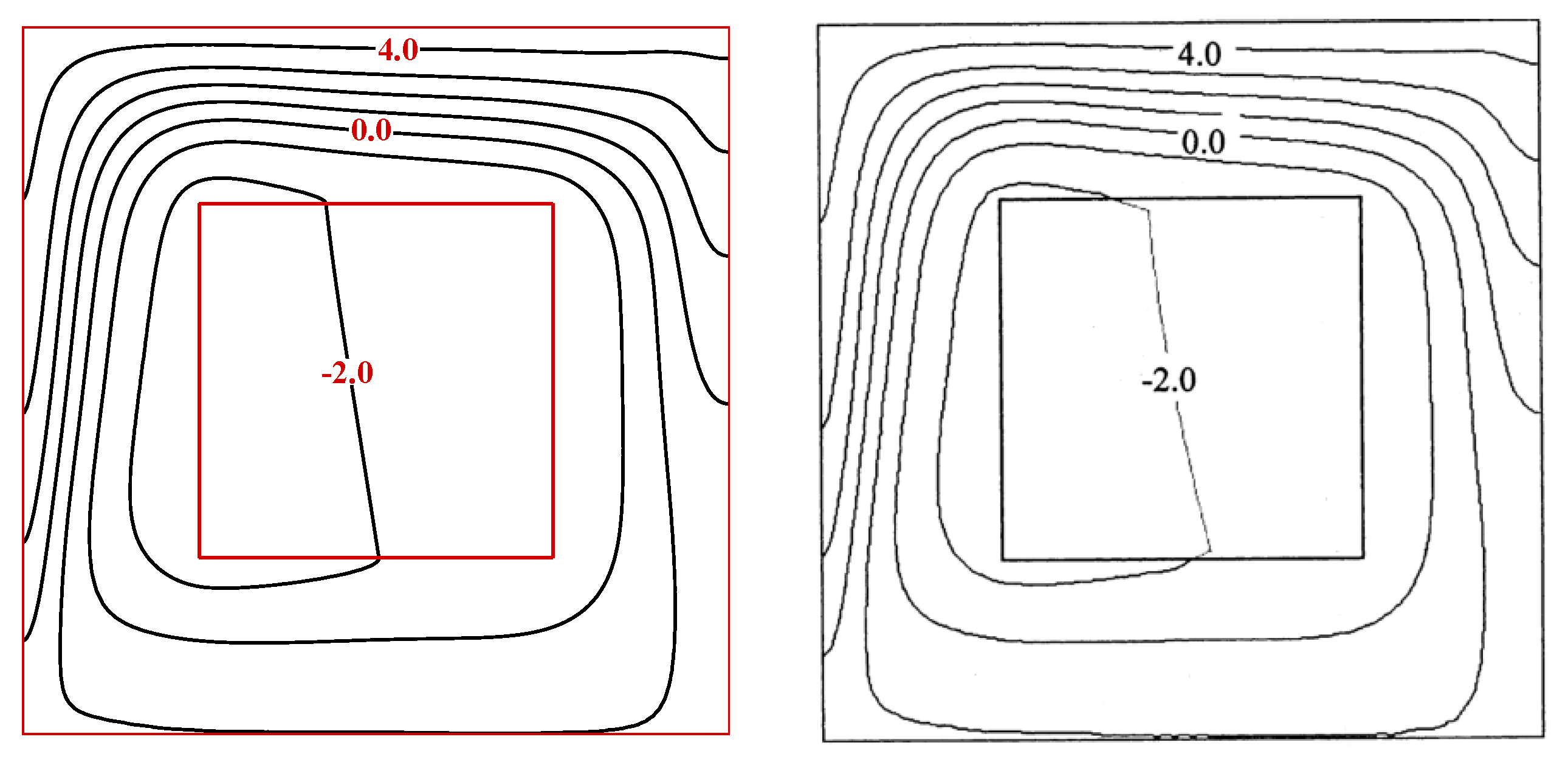
Appendix B. Validation of the Numerical Code

The validity of the developed finite element code should be checked to ensure the accuracy and correctness of the results. As such, three different research studies have been chosen and their outcomes have been re-stimulated to guarantee that all aspects of the code are fine and error-free. In Figure A2, a comparison is performed between the streamlines and isotherms of this research with another one shown by Nithiarasu et al. [35]. In [35], the buoyancy-driven flow of a simple flow has been addressed. The boundary conditions and geometry of this research are the same as the present one. It is evident that the patterns of streamlines and the isotherms are in quite a resemblance with [35], indicating that the developed code can accurately analyze the circulation and energy transference in the cavity.
Figure A2. Comparison between the isolines of air (Ra = 106, Pr = 0.71, WR = 0.3) for the present work and another one presented by Nithiarasu et al. [35].
Symmetry 13 00122 g0a2
In addition, to check that the equations governing the thermophysical characteristics of the nanofluid are appropriately implemented, the code has been further validated against a survey published by Kahveci [36] on the thermo-gravitational convection of nanosuspension in a chamber. In this research, the nano-sized particles are supposed to be easily fluidized, and hence, the solid-liquid two-phase flow of the nanoliquid is assumed to be homogenous and behaves as a single-phase fluid. The side walls in [36] are set to a temperature drop, and the upper and lower borders are adiabatic. The base fluid in work done by Kahveci [36] is water (Pr = 6.2), and the impact of dispersion of different nanoparticles (including Cu, Ag, CuO, Al2O3 and TiO2) on the circulation pattern and the rate of energy transference has been evaluated. Figure A3 depicts the comparison between the outcomes of Kahveci [36] and the present research for the dependency of the Nuavg on the concentration of Al2O3 nano-sized particles. It is apparent that the obtained values of the Nuavg coincide with the data of Kahveci [36], representing a finite element code that can appropriately simulate the thermal convective energy transference of nanoliquids in a confined chamber.
Figure A3. Influence of Al2O3 nanoparticles volume fraction on the Nuavg (Pr = 6.2, β = 0.02, θ = 0°): Comparison between the present work and outcomes of Kahveci [36].
Symmetry 13 00122 g0a3
As the final step, two more verifications have been performed to ensure that both entropy generation terms and the heat lines are correctly calculated. Figure A4 shows the isentropic lines and isolines of local Bejan number for the work done by Ilis [37] and the current study. In [37], the entropy generation resulting from free convective transport in a square chamber has been analyzed. The imposed boundary conditions are exactly the same as [36]. It is evident that both Sgen and Be are correctly calculated, and the values of similar isolines are quite similar. Finally, the survey of Deng and Tang [38], shown in Figure A5, has been utilized to check the validity of the solved heat function equation. The employed boundary conditions in [38] are exactly the same as [36,37], except that a solid rectangular solid is placed in the center of the cavity, and an extra energy equation for the solid block needs to be solved. As seen, the heat lines are in acceptable agreement with those presented by Deng and Tang [38].
Figure A4. Comparison between (left) the total entropy production and (right) the local Bejan number (Ra = 106, Pr = 0.71, WR = 0.3): Ilis [37] and the present research.
Symmetry 13 00122 g0a4
Figure A5. Comparison between the patterns of heat lines obtained by Deng and Tang [38] and the present work (Ra = 105, Pr = 0.71).
Symmetry 13 00122 g0a5

References

  1. Mansour, M.A.; Mohamed, R.A.; Abd-Elaziz, M.M.; Ahmed, S.E. Numerical simulation of mixed convection flows in a square lid-driven cavity partially heated from below using nanofluid. Int. Commun. Heat Mass Transf. 2010, 37, 1504–1512. [Google Scholar] [CrossRef]
  2. Bhattacharya, M.; Basak, T.; Oztop, H.F.; Varol, Y. Mixed convection and role of multiple solutions in lid-driven trapezoidal enclosures. Int. J. Heat Mass Transf. 2013, 63, 366–388. [Google Scholar] [CrossRef]
  3. Das, S.K.; Choi, S.U.; Yu, W.; Pradeep, T. Nanofluids: Science and Technology; John Wiley & Sons: Hoboken, NJ, USA, 2007. [Google Scholar]
  4. Tyagi, H. Radiative and Combustion Properties of Nanoparticle-Laden Liquids; Arizona State University: Phoenix, AZ, USA, 2008. [Google Scholar]
  5. Mahian, O.; Kianifar, A.; Kalogirou, S.A.; Pop, I.; Wongwises, S. A review of the applications of nanofluids in solar energy. Int. J. Heat Mass Transf. 2013, 57, 582–594. [Google Scholar] [CrossRef]
  6. Abu-Nada, E.; Masoud, Z.; Oztop, H.F.; Campo, A. Effect of nanofluid variable properties on natural convection in enclosures. Int. J. Therm. Sci. 2010, 49, 479–491. [Google Scholar] [CrossRef]
  7. Oztop, H.F.; Abu-Nada, E. Numerical study of natural convection in partially heated rectangular enclosures filled with nanofluids. Int. J. Heat Fluid Flow 2008, 29, 1326–1336. [Google Scholar] [CrossRef]
  8. Parvin, S.; Chamkha, A.J. An analysis on free convection flow, heat transfer and entropy generation in an odd-shaped cavity filled with nanofluid. Int. Commun. Heat Mass Transf. 2014, 54, 8–17. [Google Scholar] [CrossRef]
  9. Sarkar, J.; Ghosh, P.; Adil, A. A review on hybrid nanofluids: Recent research, development and applications. Renew. Sustain. Energy Rev. 2015, 43, 164–177. [Google Scholar] [CrossRef]
  10. Sidik, N.A.C.; Adamu, I.M.; Jamil, M.M.; Kefayati, G.H.R.; Mamat, R.; Najafi, G. Recent progress on hybrid nanofluids in heat transfer applications: A comprehensive review. Int. Commun. Heat Mass Transf. 2016, 78, 68–79. [Google Scholar] [CrossRef]
  11. Sundar, L.S.; Sharma, K.V.; Singh, M.K.; Sousa, A.C.M. Hybrid nanofluids preparation, thermal properties, heat transfer and friction factor—A review. Renew. Sustain. Energy Rev. 2017, 68, 185–198. [Google Scholar] [CrossRef]
  12. Ranga Babu, J.A.; Kumar, K.K.; Srinivasa Rao, S. State-of-art review on hybrid nanofluids. Renew. Sustain. Energy Rev. 2017, 77, 551–565. [Google Scholar] [CrossRef]
  13. Huminic, G.; Huminic, A. Hybrid nanofluids for heat transfer applications—A state-of-the-art review. Int. J. Heat Mass Transf. 2018, 125, 82–103. [Google Scholar] [CrossRef]
  14. Sajid, M.U.; Ali, H.M. Thermal conductivity of hybrid nanofluids: A critical review. Int. J. Heat Mass Transf. 2018, 126, 211–234. [Google Scholar] [CrossRef]
  15. Suresh, S.; Venkitaraj, K.P.; Selvakumar, P.; Chandrasekar, M. Effect of Al2O3–Cu/water hybrid nanofluid in heat transfer. Exp. Therm. Fluid Sci. 2012, 38, 54–60. [Google Scholar] [CrossRef]
  16. Aly, E.H.; Pop, I. MHD flow and heat transfer over a permeable stretching/shrinking sheet in a hybrid nanofluid with a convective boundary condition. Int. J. Numer. Methods Heat Fluid Flow 2019, 29. [Google Scholar] [CrossRef]
  17. Ismael, M.A.; Armaghani, T.; Chamkha, A.J. Mixed Convection and Entropy Generation in a Lid-Driven Cavity Filled with a Hybrid Nanofluid and Heated by a Triangular Solid. Heat Trans. Res. 2018, 49, 1645–1665. [Google Scholar] [CrossRef]
  18. Waini, I.; Ishak, A.; Groşan, T.; Pop, I. Mixed convection of a hybrid nanofluid flow along a vertical surface embedded in a porous medium. Int. Commun. Heat Mass Transf. 2020, 114, 104565. [Google Scholar] [CrossRef]
  19. Waini, I.; Ishak, A.; Pop, I. Transpiration effects on hybrid nanofluid flow and heat transfer over a stretching/shrinking sheet with uniform shear flow. Alex. Eng. J. 2020, 59, 91–99. [Google Scholar] [CrossRef]
  20. Roslan, R.; Ali, I.; Alsabery, A.I.; Bakar, N. Mixed Convection in a Lid-Driven Horizontal Rectangular Cavity Filled with Hybrid Nanofluid By Finite Volume Method. J. Adv. Res. Micro Nano Eng. 2020, 1, 38–49. [Google Scholar]
  21. Khashi’ie, N.S.; Md Arifin, N.; Pop, I. Mixed Convective Stagnation Point Flow towards a Vertical Riga Plate in Hybrid Cu-Al2O3/Water Nanofluid. Mathematics 2020, 8, 912. [Google Scholar] [CrossRef]
  22. Khashi’ie, N.S.; Arifin, N.M.; Pop, I.; Nazar, R.; Hafidzuddin, E.H.; Wahi, N. Flow and heat transfer past a permeable power-law deformable plate with orthogonal shear in a hybrid nanofluid. Alex. Eng. J. 2020, 59, 1869–1879. [Google Scholar] [CrossRef]
  23. Khashi’ie, N.S.; Arifin, N.M.; Pop, I.; Nazar, R.; Hafidzuddin, E.H.; Wahi, N. Three-Dimensional Hybrid Nanofluid Flow and Heat Transfer past a Permeable Stretching/Shrinking Sheet with Velocity Slip and Convective Condition. Chin. J. Phys. 2020, 66, 157–171. [Google Scholar] [CrossRef]
  24. Ali, I.; Alsabery, A.I.; Bakar, N.; Roslan, R. Mixed Convection in a Double Lid-Driven Cavity Filled with Hybrid Nanofluid by Using Finite Volume Method. Symmetry 2020, 12, 1977. [Google Scholar] [CrossRef]
  25. Khan, M.R.; Pan, K.; Khan, A.U.; Nadeem, S. Dual solutions for mixed convection flow of SiO2−Al2O3/water hybrid nanofluid near the stagnation point over a curved surface. Phys. A Stat. Mech. Appl. 2020, 547, 123959. [Google Scholar] [CrossRef]
  26. Liu, W.; Al-Rashed, A.A.; Alsagri, A.S.; Mahmoudi, B.; Shahsavar, A.; Afrand, M. Laminar forced convection performance of non-Newtonian water-CNT/Fe3O4 nano-fluid inside a minichannel hairpin heat exchanger: Effect of inlet temperature. Powder Technol. 2019, 354, 247–258. [Google Scholar] [CrossRef]
  27. Devi, S.U.; Devi, S.A. Heat transfer enhancement of cu− $ al_ {2} o_ {3} $/water hybrid nanofluid flow over a stretching sheet. J. Niger. Math. Soc. 2017, 36, 419–433. [Google Scholar]
  28. Takabi, B.; Salehi, S. Augmentation of the heat transfer performance of a sinusoidal corrugated enclosure by employing hybrid nanofluid. Adv. Mech. Eng. 2014, 6, 147059. [Google Scholar] [CrossRef]
  29. Sheremet, M.A.; Cimpean, D.S.; Pop, I. Thermogravitational convection of hybrid nanofluid in a porous chamber with a central heat-conducting body. Symmetry 2020, 12, 593. [Google Scholar] [CrossRef] [Green Version]
  30. Chamkha, A.J.; Mansour, M.A.; Rashad, A.M.; Kargarsharifabad, H.; Armaghani, T. Magnetohydrodynamic mixed convection and entropy analysis of nanofluid in gamma-shaped porous cavity. J. Thermophys. Heat Transf. 2020, 34, 836–847. [Google Scholar] [CrossRef]
  31. Alsabery, A.I.; Tayebi, T.; Roslan, R.; Chamkha, A.J.; Hashim, I. Entropy Generation and Mixed Convection Flow Inside a Wavy-Walled Enclosure Containing a Rotating Solid Cylinder and a Heat Source. Entropy 2020, 22, 606. [Google Scholar] [CrossRef]
  32. Costa, V. Bejan’s heatlines and masslines for convection visualization and analysis. Appl. Mech. Rev. 2006, 59, 126–145. [Google Scholar] [CrossRef] [Green Version]
  33. Reddy, J.N.; Gartling, D.K. The Finite Element Method in Heat Transfer and Fluid Dynamics; CRC Press: Boca Raton, FL, USA, 2010. [Google Scholar]
  34. Zienkiewicz, O.; Taylor, R.; Nithiarasu, P. The Finite Element Method. In Fluid Dynamics; Butterworth-Heinemann: Oxford, UK, 2005; Volume 3. [Google Scholar]
  35. Nithiarasu, P.; Sundararajan, T.; Seetharamu, K. Finite element analysis of transient natural convection in an odd-shaped enclosure. Int. J. Numer. Methods Heat Fluid Flow 1998, 8, 199–216. [Google Scholar] [CrossRef]
  36. Kahveci, K. Buoyancy driven heat transfer of nanofluids in a tilted enclosure. J. Heat Transf. 2010, 132, 062501. [Google Scholar] [CrossRef]
  37. Ilis, G.G.; Mobedi, M.; Sunden, B. Effect of aspect ratio on entropy generation in a rectangular cavity with differentially heated vertical walls. Int. Commun. Heat Mass Transf. 2008, 35, 696–703. [Google Scholar] [CrossRef] [Green Version]
  38. Deng, Q.-H.; Tang, G.-F. Numerical visualization of mass and heat transport for conjugate natural convection/heat conduction by streamline and heatline. Int. J. Heat Mass Transf. 2002, 45, 2373–2385. [Google Scholar] [CrossRef]
Figure 1. Schematic geometry of the problem.
Symmetry 13 00122 g001
Figure 2. The impact of WR and Ra on (a) isotherms, (b) heat lines, (c) streamlines and (d) total isentropic lines when Pr = 6.2, ϕhnf = 0.05 and ϕr = 0.5.
Symmetry 13 00122 g002aSymmetry 13 00122 g002b
Figure 3. The variation of average (a) Nu and (b) Be numbers against nanofluid volume fractions in various Ra for Pr = 6.2, WR = 0.3 and ϕr = 0.5.
Symmetry 13 00122 g003
Figure 4. The variation of (a) Nuavg and (b) Be numbers against ϕr with different values of wall width ratio (ϕhnf = 0.05, Ra = 103 and Pr = 6.2).
Symmetry 13 00122 g004
Figure 5. The variation of (a) Nuavg and (b) Be numbers against ϕr with different values of wall width ratio (ϕhnf = 0.05, Ra = 105 and Pr = 6.2).
Symmetry 13 00122 g005
Figure 6. The impact of Ra and hybrid nanoparticles concentration on (a) entropy production due to energy transference, (b) the portion of generated entropy caused by friction of the hybrid nanofluid, and (c) total entropy production for WR = 0.3, Pr = 6.2 and ϕr = 0.5.
Symmetry 13 00122 g006
Table 1. Thermal characteristics of Cu and Al2O3 nanoparticles [29].
ρ (kg·m−3)c (J·kg−1·K−1)k (W·m−1·K−1)α (m2·s−1) × 107β (K−1) × 106
Al2O3397076540131.725.5
Cu89333854001163.150.1
Host fluid (water)997.14179.00.6131.47210
Publisher’s Note: MDPI stays neutral with regard to jurisdictional claims in published maps and institutional affiliations.

