
Intelligent Safety Assessment of Prestressed Steel Structures Based on Digital Twins

1
Faculty of Architecture, Civil and Transportation Engineering, Beijing University of Technology, Beijing 100124, China
2
The Key Laboratory of Urban Security and Disaster Engineering of the Ministry of Education, Beijing University of Technology, Beijing 100124, China
*
Author to whom correspondence should be addressed.
Symmetry 2021, 13(10), 1927; https://0-doi-org.brum.beds.ac.uk/10.3390/sym13101927
Submission received: 8 September 2021
/
Revised: 8 October 2021
/
Accepted: 9 October 2021
/
Published: 14 October 2021
(This article belongs to the Special Issue Symmetry in Structural Health Monitoring)
Abstract
:In the development process of intelligent construction, the safety assessment of prestressed steel structures as an important research direction has become more and more attractive in academia. Digital twins (DTs) is the key technology to realize intelligent construction. The virtual and real interaction of the DTs can provide an efficient management and control mechanism for the construction process. This research proposes an intelligent safety assessment method of prestressed steel structures based on DTs. In this research method, the structural safety assessment is divided into two aspects: performance analysis and maintenance. By analyzing the characteristics of the construction safety assessment, a DTs framework for construction safety assessment is built. Driven by the DTs framework, a physical space model and a virtual space model are constructed. On the basis of virtual and actual interaction, multidimensional information fusion of time and space is carried out to realize the analysis of structural safety performance. On this basis, the paper establishes a Bow-tie model for the maintenance modeling of unsafe construction events. Moreover, the theoretical method formed is applied to the construction of a symmetrical structure (wheel–spoke cable truss). The validity of the method is verified by comparing the cable force calculated by the theoretical method and measured on site. The assessment method driven by the DTs ensures the structural safety and improves the intelligence level of safety management and control of the structure construction.
1. Introduction
In recent years, the construction industry is gradually developing towards digitalization, informatization, and intelligence [1]. The construction safety of prestressed steel structures is a widespread concern in the engineering field. Under the continuous progress of science and technology, the construction technology level of prestressed steel structures has been significantly improved. Facing the construction process, many new technologies, new processes, and new equipment have emerged. The structural deformation of prestressed steel structures is often the reverse to the deformation under load, so that the structural stiffness is improved. Therefore, it is commonly used in significant buildings, such as large stadiums [2]. Structural construction has the characteristics of complex links and numerous abnormal disturbance factors. Improving the accuracy and intelligence level of the safety assessment of the prestressed steel structure will directly reflect the construction ability of the country. Besides, safety control of the prestressed steel structure construction process has also become a hot topic in the research field of civil engineering. This study uses the mechanical parameters of the structure as an important basis for measuring the safety performance. Through the analysis of mechanical parameters, intelligent control of construction safety is realized.
For the structural construction safety control, researchers have developed various approaches to improve the accuracy of the analysis. Wang et al. [3] focused on the analysis of cable force, which is the most active parameter in the construction process of spatial structure prestressed cables. In the whole process of prestressed cable tension, the safety of the construction process of the structure is ensured by analyzing the cable force. To ensure the stability of the cable dome structure in the construction process, Zhang et al. [4] proposed a kind of square double-strut cable dome structure. This structure effectively improved the safety control precision of the structure tension process. Liu et al. [5] obtained the reliability index of the cable by the response surface method and the Monte Carlo method, and then analyzed the influence of cable relaxation on structural reliability. The research results provide a basis for safety assessment of the wheel–spoke cable truss structure when prestress loss occurs. Bai et al. [6] investigated the seismic behavior of steel beam–column connections with an outer annular stiffener under bi-directional cyclic loadings. The seismic performance is analyzed to ensure the safety performance of the structure, which provides a reference for the normal operation of the structure under complex loads. Liu et al. [7] studied the dynamic response of a typical umbrella membrane structure under heavy rainfall by experimental and numerical methods. They put forward suggestions on the safety and structural stability of the membrane structure. Basta et al. [8] studied the quantitative evaluation of the decomposability of the cable-net structure based on building information modeling (BIM). Alamdari et al. [9] proposed a new damage identification technology for the safety performance evaluation of long-span spatial structures based on the concept of rotation influence line (RIL). This method effectively improves the efficiency of structural safety performance evaluation. Bera et al. [10] studied the active control of the safety performance of long-span cable-stayed bridges. Two finite element (FE) modeling schemes are adopted, namely one-element cables and multi-element cables, with each stay-cable discretized into multiple elements to consider the cable vibration effect. Considering that the long-span cable will vibrate under different weather conditions, D’Auteuil et al. [11] developed a new type of wind- and rain-induced vibration test.
In summary, experts and scholars of civil engineering have performed a lot of research and exploration in structural safety assessment. However, these studies only focus on the performance of the structure in a certain construction stage, ignoring the dynamics and uncertainty of the construction process. Therefore, it is necessary to integrate multidimensional information of the structure to solve the problem of real-time safety analysis during the whole construction process. How to integrate multi-source heterogeneous information in time and space dimensions to improve the intelligence of safety performance assessment is still in the exploratory stage. The above-mentioned issues require real-time analysis of structural mechanical properties and effective maintenance of construction unsafe events. Meantime, how to improve the intelligence of construction safety assessment of prestressed steel structures is a new direction of current research [12]. In order to improve the intelligence of safety assessment, it is a requisite to realize multidimensional information fusion in the construction process. Through the intuitive mapping of the virtual space to the actual construction, the construction of the physical world is guided by the simulation model. By analyzing the virtual model, each step of the construction is ensured to be in a safe state. In order to improve the intelligence of the safety assessment, the dynamic perception of each stage should be realized, and the real-time simulation and analysis of the structure can be carried out from the virtual space. The maintenance measures for unsafe incidents are developed based on the analysis results. The feasibility of decision-making is analyzed in the virtual space and accurately guides the entire construction process. Finally, the intelligent closed-loop control of structural safety is realized. In intelligent manufacturing, digital twins (DTs) are the key enabling technology to achieve multi-source information fusion. The introduction of DTs from manufacturing to the construction industry will provide new ideas for the intelligent construction of structures [13,14].
DT establishes a multidimensional dynamic virtual model within multi-spatial scale, multi-time scale, and multi-physical entities through digitization. The virtual model can simulate the attributes, behaviors, and performances in the real environment [15]. DTs have the characteristics of rapid information exchange and extensive representation of live scenes. DTs are not only widely utilized in the practical construction area but are also applied by researchers in the investigation as one of the necessary parts. Professor Grieves of the University of Michigan formally proposed the concept of DTs in 2003 [16]. The virtual digital model of twins can abstractly map the performance of physical entities by simulating the state and behavior of products. Yu et al. [17] provided new method based on DTs technology and machine learning for accurately and timely predicting pavement performance. The new method solved the problem of pavement performance evaluation. In spite of the difficulty for a single enterprise to achieve large-scale and personalized task requirements, Tao et al. [18] pointed out that by manufacturing service collaboration, driven by DTs technology and industrial Internet platforms, cross-enterprise manufacturing collaboration was realized. Combined with the visual question-answering technology in artificial intelligence, Wang et al. [19] applied the digital twin model to human–computer collaboration tasks. This progress created the possibility for real-time simulation and optimization and formed an on-demand intelligent service system. Ruppert et al. [20] proposed a DTs model by combining the advantages of information fusion and real-time location systems. The DTs model can continuously predict the production status and provide information for production performance monitoring. Gopalakrishnan et al. [21] pointed out that manufacturing requires digital transformation. They created a DT model-based feature information network (MFIN), which realized the digital description of components or systems. Thus, DT is widely used in the manufacturing industry and can effectively improve the intelligence level of manufacturing processes. However, it is relatively less used in the construction industry. In order to improve the intelligence level of the construction industry, it is necessary to introduce DTs. Aiming at the research hotspot about intelligent assessment of structural safety performance, this paper proposes an intelligent safety assessment method of prestressed steel structures based on DTs. In terms of structural safety assessment, previous studies have conducted a detailed analysis of mechanical parameters. In order to improve the intelligence of construction safety assessment, the concept of DTs is introduced, and the whole assessment process is divided into safety performance analysis and unsafe event maintenance. Driven by the DTs, the virtual and real spaces are integrated to realize dynamic perception and intelligent collection of the construction process. At the same time, it is necessary to consider the temporal and spatial evolution of each element of the construction process. Therefore, intelligent algorithms are integrated for real-time analysis of structural safety. The maintenance measures for unsafe events are formulated, and the feasibility of decision-making is analyzed in the twin model. In the end, it accurately guides the construction site. In this study, through the analysis of the characteristics of construction safety assessment, an intelligent assessment framework based on DTs is firstly established. Driven by this framework, three kinds of information from real construction are captured to support the construction of the virtual model. After the completion of the virtual model, the time dimension and space dimension information of the construction process are fused by Markov chain. Thus, the structural safety performance of each construction step is analyzed intelligently. In view of unsafe events, the maintenance model of that in construction is carried out based on the Bow-tie model. The corrective measures are formulated in the maintenance model to ensure the safety of the structure in each construction step. The resulting DTs assessment theory is applied in the construction process of a wheel–spoke cable truss. This research method effectively improves the informatization and intelligence of the safety assessment in the construction process. This research method provides a reference for the health monitoring of the symmetric structure in the operation and maintenance stage. In brief, this work makes the following contributions:
- (1)
- A DTs framework is proposed, and a construction safety assessment method driven by DTs is formed.
- (2)
- Driven by the assessment method, a multidimensional DT model for structural safety analysis is constructed.
- (3)
- In view of the unsafe events in the construction process, the maintenance modeling is carried out to ensure the structure in a safe state in each construction step.
- (4)
- A case study is used to prove the superiority of the proposed method in improving the intelligence of the structural safety assessment.
The remainder of the paper is structured as follows. Section 2 summarizes the characteristics of construction safety assessment, builds a DT framework for construction safety assessment, and forms a DT-driven construction safety assessment method. Section 3 describes the details of the construction of a multidimensional DT model to analyze the structural safety performance. Section 4 establishes the maintenance model of construction unsafe events to ensure the safety of the structure. Section 5 illustrates the case study used to verify the proposed method, with a further discussion in Section 6. Finally, conclusions are drawn in Section 7.
2. Construction Safety Assessment Method Driven by DTs
2.1. Characteristics of Construction Safety Assessment
In the construction process of prestressed steel structures, the reliability of the structure is an important prerequisite to ensure the construction quality [22]. However, in the construction process, the integrity of the structure is not stable enough, the material properties of the components are time-varying, and the structural resistance is not mature. In addition, the environmental effects of the construction process are also uncertain [23]. Therefore, the probability of safety accidents in the construction stage is high. According to the structural safety performance analysis of the construction process, the parameters are nonlinear, linkage, and change with time. Therefore, the construction safety assessment is a multidimensional mechanical problem coupling time and space. The characteristics of the construction process are as follows:
- (1)
- Construction complexity: Prestressed steel structure construction is a complicated systematic project. In the construction process, the materials, equipment, sequence, and technology are interactive. Various types of external factors are superimposed on the structure. In addition, the change of structural mechanical properties is a nonlinear process with noise, which causes difficulty in structural safety assessment.
- (2)
- Time correlation: The external action and mechanical properties of components in the process of structural construction are time-varying. This feature is directly reflected in the data collected by various sensing devices.
- (3)
- Factor linkage: The structural construction process involves the multi-factor conversion of material, energy, and information. This feature has caused problems such as huge construction system modeling and cumbersome multi-element management and control.
2.2. DT Framework for Construction Safety Assessment
According to the characteristics of the construction process, it is necessary to establish a DTs model. This model monitors the structure in real-time and improves the accuracy and intelligence of the safety assessment. DTs visually reproduce the real physical entity by building a virtual space model to simulate the dynamic behavior of the entity in the real environment [24]. Many scholars have applied the framework of DTs in vehicles, ships, power plants, complex electromechanical equipment, satellite/space communication networks, three-dimensional warehouses, medical treatment, aircraft, smart city, and other fields [25]. Combined with the characteristics of construction safety assessment, this study builds a DT framework for the construction safety assessment of prestressed steel structures. The DT framework is shown in Figure 1.
The DT framework for the safety assessment of prestressed steel structures’ construction is composed of five dimensions, namely, physical construction site, virtual construction model, twin data processing layer, the functional application layer of safety assessment, and the connection layer between components. Based on the physical construction site, the virtual construction model is established. From the perspective of virtual–real interaction, the virtual model includes four levels: geometry, physics, behavior, and rule. The various types of information on the physical construction site are dynamically collected by RFID and other sensing equipment [26]. Information is fed back into the virtual construction model in real-time. In the virtual construction model, the working condition parameters consistent with the actual construction are set. By adjusting the mechanical parameters of the structure, the virtual model simulates the actual construction state of the structure. The twin data of the construction process are formed by the data collected from the physical construction site and the simulation data in the virtual construction model. The twin data contain multiple construction elements, such as personnel, machinery, material, construction method, and environment, in the construction process. In the twin data processing layer, the data are modeled by a machine learning algorithm to realize the high integration of spatial elements and time dimensions in the construction process. Therefore, the structural safety performance of each construction step is analyzed. Based on the analysis of structural safety performance, the maintenance model of construction unsafe events is established to accurately predict and implement the unsafe events. By setting up a construction framework for prestressed steel structures, a construction safety assessment method driven by DTs is formed. Through the dynamic perception of the real construction information, the virtual mode can evaluate the safety performance. The maintenance measures for unsafe events are formulated, and the feasibility of decision-making is analyzed in the twin model. In the end, the measure accurately guides the construction site. The intelligent closed-loop control of the structural safety assessment in the construction process is realized.
This study divides the construction safety assessment method driven by DTs into two levels, as shown in Figure 2. The first level is the construction of the multidimensional model based on DTs. This level includes the information capture of the physical construction site, the construction of the virtual construction model, and the integration of time and space information in the construction process. The second level is the maintenance of construction unsafe events based on the Bow-tie model. This level focuses on the qualitative analysis of unsafe events and the precise maintenance of unsafe events. Logically, the former is the foundation of the latter, and the latter is the expansion and extension of the former.
3. Construction of Multidimensional DTs Model
Driven by the DT framework, the multidimensional model is constructed. The multidimensional model is composed of the capture of physical space information, the construction of virtual models, and the fusion of spatiotemporal information in the construction process. The research on the three aspects above can realize the integration of multiple factors in the time and space dimensions of the construction process. The fusion of information provides the basis for the safety analysis of each construction step in the construction process. The results of the analysis are the basis for the maintenance of unsafe events. The three components of the DTs model are described as follows.
3.1. Information Capture in Physical Space
In the process of constructing a multidimensional DTs model, the information capture of physical space is the first step to realize the safety assessment. The dynamic information of the construction site can be sensed in real-time through sensing equipment such as RFID. This realizes the one-to-one mapping between the real space and the virtual model [27]. The main analysis objects of the safety assessment of building structures are structural response and environmental loads [28]. Hence, this study divides the information of physical space into two aspects, namely component information (CI) and environmental information (EI).
- (1)
- Component information capture
There are many kinds of components involved in the construction process of prestressed steel structures, and the construction sequence of each component is complicated. Therefore, the information capture of various components in the construction process is of great significance to the safety performance assessment. In the process of component information capture, the main information is divided into the component symbol (CS), basic information (BI), construction information (CI*), and mechanical information (MI). The mathematical language for information capture of components is expressed in Equations (1)–(4):
BIi = (CDi, CLi, CMi, Uniti, Datai)
MIi = (Ei, Cfi, εi, Vdi)
In the equations, CIi represents the component information for the ith component, CSi means the unique identifiable ID bound by the ith component, and BIi is the basic attribute set of the ith component. BIi contains the dimension information (CDi), the locating information (CLi), the material information (CMi), the production unit (Uniti), and the date of production (Datai). is the construction information of the ith component. contains the construction process (CPi), construction technology (CTi), construction quality requirements (QRi), and the time (Ti) used in this step. MIi means the mechanical information of the ith component in the construction process. MIi involves the elastic modulus (Ei), cable force (Cfi), stress (εi), vertical displacement (Vdi), and other mechanical properties.
In the process of capturing component information, the symbol, basic information, and construction information of the component are filled in the active RFID tag. For structural components, the relevant information is updated through the RFID tag at all times to realize the dynamic perception of the information. For the information change of the construction process component, the editability of the label can be used to modify it through the reader. As a result, the basic information and construction information of the component can be viewed in real-time in the mobile terminal device. For the capture of mechanical information of components, the mechanical parameters of components are collected by sensors for each construction step. Cable force is the key information collected in the study and the basis for evaluating the safety performance of the structure. This type of information is collected in real-time by the column tension-compression sensor in the test. By arranging sensing devices on the components, the efficiency of information collection and update is improved. Therefore, the self-perception, self-decision, and self-execution of the components can be realized to a certain extent. The real-time information is captured by the sensing equipment at each construction step. Structure information of the scene is collected and has interactive feedback with the virtual model. Virtual and real interaction provides twin data for the intelligent assessment of structural safety.
- (2)
- Environmental information capture
In the process of structural construction, there are many reasons causing structural damage. In the structural safety assessment, the effects of various external influence factors are comprehensively analyzed [29]. The component length error (Le), wind load effect (Wl), and temperature effect (Te) are captured and perceived emphatically in the process of environmental information capture. The mathematical language expression of environmental information capture in the construction process is shown in Equation (5):
EI = (Le, Wl, Te)
In the process of capturing environmental information, RFID technology is used to collect the size of the component in real-time. The error of the cable length is dynamically updated through the mobile terminal device. The length error of structural components due to processing, installation, and other reasons has an important impact on the safety performance of the structure. In view of the length change of the cable, the key coordinates are picked up by three-dimensional laser scanning in each step of construction. The point cloud data are structured through on-site scanning. According to the point cloud data, the point cloud model is built in real-time. Finally, the length error of the component can be captured. On account of the editable RFID reader, using mobile terminals to identify tags on components can record and update their status. The effect of wind load and temperature is collected by the wind speed sensor and temperature sensor in real-time. These messages provide the basis for the setting of virtual model conditions and the analysis of structural safety performance. In the process of extracting wind speed and temperature information, a complete set of sensing equipment is applied to perceive the environmental information of the scene. By arranging sensors in the construction process and setting control modules, the collected data are visually presented through the display module. Finally, the environmental information collected on the site is input into the terminal equipment by Wi-Fi transmission.
In this study, the experimental model was built indoors. For the effect of wind load and temperature, the test equipment is used to generate the wind speed and temperature effect, similar to the actual working condition. At the same time, the sensor equipment is used for the setting of virtual model conditions and the evaluation of structural safety performance. The sensing equipment is arranged on the site, and the temperature of the field anemometer is dynamically perceived by the acquisition module. The information data are presented in real-time by the display module. Finally, the information query of each construction step is carried out by the Wi-Fi module in the mobile terminal. Environmental sensing devices and information are shown in Figure 3.
Through the collection of component information and environmental information in the construction process, the structural safety performance can be predicted. Information capture in physical space is shown in Figure 4. At the same time, on the basis of collecting construction site information, the virtual model can be built. The safety performance of the structure is simulated by setting the same working condition as the construction site in the virtual model. Accurate simulation achieves the goal of mapping the construction site and guiding the construction process.
3.2. Construction of Virtual Model
In the DT framework, the construction of the virtual model is divided into four levels of “geometry–physics–behavior–rule”. According to the actual construction process, each dimension model is associated and integrated to realize the deep, multi-angle, and comprehensive simulation.
The first step of virtual model establishment is modeling basic information of appearance, size, and type of components at the geometric level. The geometric model is mainly established by BIM modeling software such as Revit [30]. By establishing a high-fidelity geometric model, the geometric characteristics of the construction process can be truly mapped. Simulation mapping provides strong support for the subsequent analysis of the physical model. In this process, a three-dimensional laser scanner is required to extract the geometric form of the site structure at each construction step. The geometric model is adjusted in real-time from the point cloud data. The scanning accuracy of this method can reach a reliable level of 0.1 mm. This method uses laser scanning technology to scan the three-dimensional information of the component. The generated point cloud data model can be directly converted into CAD or BIM software. The reverse modeling of the component is realized, and the digital model that meets the accuracy requirements is obtained. In this process, the target paper is arranged on the site. The structure is scanned for each construction step to extract the coordinates of key nodes.
During the construction of the test model, the real structure is scanned by a three-dimensional laser scanner to obtain the measured model of the structure. After obtaining the point cloud data, the necessary task is to denoise. This link can remove the outliers deriving from the machine error, human factors, or the external environment. Then, the remaining data are imported into BIM software, while the key points of the cable truss structure are extracted. The coordinate correction of the theoretical BIM model is carried out to obtain the modified BIM model. The coordinates of key nodes are extracted from the modified BIM model to modify the theoretical finite element analysis model. Finally, the modified finite element analysis model considering the time dimension is obtained. At the physical level, the material parameters of construction components are mainly simulated in the physical model by finite element analysis software such as ANSYS. In this process, with the collected data of the sensing equipment, the geometric model and the connection parameters of the components in the model are modified. The calculation of structural mechanical properties during construction is realized by the physical model in the end. As is known, the size of the component will affect the mechanical properties of the structure. In this study, the section area of cable is adjusted by comparing the measured value of cable force with the simulation value. Area adjustment improves the fidelity of the physical model. The geometric model and physical model are established to describe the construction site and provide model support for the safety assessment. At the behavior level, the finite element model can set the working conditions matching the actual construction. The mechanical properties of components and the changes of the parameters of the material itself under the action of working conditions are analyzed. The material parameters and mechanical properties’ parameters extracted in this way can be directly used for the assessment of construction safety. According to the analysis of the finite element model, the transition probability of safety state analysis can be obtained. On the basis of the change of working conditions, the safety performance of the structure can be analyzed in advance, as detailed in Section 3.3. Through the analysis of the physical model and the integration of time dimension information, the real-time data collection of the whole construction process can be carried out. The changes of material parameters and mechanical properties in the spatio-temporal evolution process are obtained. In the whole process of building the virtual model, it is necessary to establish a rule model to limit the simulation and ensure the feasibility and scientificity of the analysis. At the rule level, according to the standard specification, the mechanical properties’ parameters of the components in the construction process should be quantitatively limited. The rule model is the reference standard for quality control, risk prediction, and decision optimization. The unsafe events of the structure should be avoided by establishing the maintenance model and setting the correction measures. Consequently, the feasibility analysis is carried out in the finite element model to guide the field construction, as shown in Section 4. The internal relations of the four levels of the virtual model are shown in Figure 5.
The mathematical language of DTs’ virtual modeling is expressed as Equation (6):
where VM represents a virtual model in a DT framework for safety assessment of prestressed steel structure construction. The elements in the model set are represented as a geometric model set (GMset), physical model set (PMset), behavior model set (BMset), and rule model set (RMset). All kinds of model sets are connected by a natural connector (⋈). Model integration realizes the simulation of the full elements, and multidimensional and multi-state of the physical construction site. In the related process of various models, the geometric model and physical model are adjusted by using a three-dimensional laser scanner, sensors, and other equipment. Therefore, the model can map the state of the real structure. At the same time, the information of each construction step is analyzed by Markov chain to realize the information fusion of the time dimension and space dimension in the construction process. Thus, the behavior model is effectively connected with the geometric and physical models to achieve the goal of real-time evaluation of structural safety performance. In Section 3.3, the spatio-temporal information fusion of the construction process based on Markov chain is mainly explored. The rule model runs through the whole process of building the virtual model. The rule model adjusts the geometric, physical, and behavioral models in real-time to ensure that the construction steps are in a safe state.
VM = (GMset ⋈ PMset ⋈ BMset ⋈ RMset)
3.3. Space–Time Information Fusion in Construction Process
During the construction process, the construction elements change with time. The rigidity of the structure is gradually formed, and the structure has undergone large deformations during the construction process. The next construction stage must be based on the previous step and depends on all previous construction steps. It follows that the analysis of structural safety performance belongs to the category of construction mechanics. Based on picking up physical construction information and establishing a virtual model, it is necessary to fuse the information of time and space dimensions and establish a data analysis model for the safety assessment. Markov chain [31] is a tool for the immediate transfer process and an important branch of machine learning. In this mode, the structural state of the next period is only related to the state of this period, while each period before this period is irrelevant. This process is suitable for the safety performance analysis between the adjacent construction steps in the construction process. Combined with the threshold of the main control factors in the construction process, the probability of structural safety and unsafe events is formulated. The structural safety performance of the next construction step is predicted. This requires reference to the safety performance of the current one and the probability of occurrence of risk factors or the degree of structural mechanics parameters’ change. The safety risk factors mainly include operational errors and sharp changes in environmental factors. This study takes the cable force of each construction step as the research object. When the cable force is greater than or equal to the design value of the cable force of the construction step, it is denoted that the structural safety performance is at level a. When the cable force is greater than or equal to 93% of the design value of the cable force of the construction step, it is denoted that the structural safety performance is at level b. When the cable force is greater than or equal to 90% of the design value of the cable force of the construction step, it is denoted that the structural safety performance is at level c. When the cable force is less than 85% of the design value of the cable force of the construction step, it is denoted that the structural safety performance is at level d. Structure construction information fusion based on Markov chain is shown in Figure 6.
In the process of Spatio-temporal information fusion, the state of the structure is divided into four categories according to the safety performance level. Assuming that the random variable (n = 1,2,3…) represents the structural state of the nth construction step, means that the structural safety performance is at level a, represents that the structural safety performance is at level b, indicates that the structural safety performance is at level c, and means that the structural safety performance is at level d. represents the probability that the nth construction step structure is in state i, namely , where i is 1, 2, 3, or 4. represents the probability that the current construction step structure state is i and the next construction step structure state is j, namely , where i, j = 1, 2, 3, or 4. In this study, the conversion probability () is obtained by comparing the cable force between the construction steps with the condition setting of the finite element model. In this process, the cable force of the structure is obtained in the finite element model, which generates the safety level of the structure. The transition probability can be obtained from the change of safety levels of multiple components of the structure. According to the current safety state and the change of working conditions, the safety state of the structure in the next construction step can be predicted. Thus, the prediction of structural safety performance during construction can be realized, and the prediction formula is expressed as Equation (7):
In the construction process of the structure, the mechanical properties of the structure should be analyzed timely and accurately. According to the current structural performance and working conditions, the safety performance of the next construction step is effectively predicted. In this process, the Markov chain is used to connect each construction step. The safety performance of the structure in the next period is analyzed by combining the previous structural state and the changes in construction conditions. In space, the cable force of the structure is collected in real-time, and the mechanical properties of the whole structure are fully considered. The application of Markov chain in the safety assessment of a construction process realizes the integration of construction factors. The whole process fully considers the changes of construction factors in a time dimension. The information fusion of the space–time dimension of the construction process provides a basis for the safety performance analysis of each construction stage. The analysis results provide a reference for the maintenance of unsafe events. The simulation and guidance of real construction can be realized by simulation in virtual space. The data association model of the prestressed steel structure construction process based on Markov chain is shown in Figure 7.
4. Maintenance Modeling of Construction Insecurity Incidents
In the process of structural construction, the unsafe events should be timely regulated to ensure the quality of structural construction [32]. The premise of analysis and maintenance of structural construction unsafe events is to build a model. This model can describe the occurrence of events qualitatively or quantitatively. The Bow-tie model [33] integrates many factors, such as the cause of the accident, preventive measures, possible consequences, and corresponding control measures. The unsafe event maintenance process is divided into two levels: fault tree (FT) and event tree (ET). In this study, the maintenance modeling of construction unsafe events is carried out by constructing the Bow-tie model [34].
In the model of this study, the whole maintenance model is divided into two levels: FT and ET, which are connected by the top event (TE). The leftmost side of the Bow-tie model is the risk source of structural unsafe events in the construction process. The risk source mainly includes operational errors and drastic changes in environmental factors during the construction process. The control measures for unsafe events are proposed in the maintenance model. By the above steps, combined with the simulation of the virtual model and the actual construction of the site, the safety performance of the structure is analyzed. If the safety state of the structure is at level a under preventive measures, the next construction step will continue. On the contrary, if the safety performance of the structure cannot reach the standard, the state is judged as an unsafe event, namely TE in the Bow-tie model. According to TE, the formulated corresponding control measures finally realize the effective maintenance of the structure. The safety performance index of the structure under the construction step is recorded as the result of the Bow-tie model. The principle of the Bow-tie model is shown in Figure 8.
The whole process control from risk source analysis to construction result evaluation is realized by constructing the Bow-tie model. This solves the problems of insufficient model quantification, serious block segmentation, weak intuition, and pertinence in structural safety accident analysis. The maintenance model constitutes a visual summary map to show the causes and consequences of unsafe events.
Based on the qualitative analysis of the causes and consequences of unsafe events, the values of variables in each link involved in the Bow-tie model are determined. Thus, the quantitative analysis of structural maintenance can be carried out according to the sequence of events and their internal relations. In the process of maintaining unsafe events, the whole model is divided into five types of events, namely basic event (BE), intermediate event (IE), top event (TE), control event (CE), and result event (RE). The formal mathematical language for various events is expressed as Equations (8)–(12):
BE = (BE1, BE2, …, BEn)
IE = (IE1, IE2, …, IEm)
TE = (TE1, TE2)
CE = (CE1, CE2, …, CEk)
RE = (RE1, RE2, …, REs)
In the equations, BE represents the basic event, corresponding to the risk source in the Bow-tie model, and IE means the intermediate event, corresponding to preventive measures in the Bow-tie model. In the analysis, this model assumes that there are n kinds of risk sources and m kinds of preventive measures. TE is the top event. The TE is divided into two types: security events (structural safety performance at level a) and unsafe events (structural safety performance at levels b, c, and d). Maintenance measures are needed for unsafe events. CE means the control event, that is, the maintenance measures taken for unsafe events. RE is the result event, which is the state of the structure after the adoption of maintenance measures. In this model, it is assumed that k control measures are adopted for unsafe events, and s result events are finally obtained. The maintenance schematic diagram of construction unsafe events based on the Bow-tie model is shown in Figure 9.
Assuming that the basic events are independent of each other, the probability of each basic event is in the virtual–real interaction mode. The probability of the intermediate event is through the logical relationship. Combined with Markov chain, the probability of the top event () can be calculated by spatio-temporal information fusion of the construction process. Calculating the probability of RE occurrence should consider the possibility that the existence of L branches can lead to the occurrence of the ith result event (REi). Assuming that the occurrence probability of the control event on the tth (t < l) branch is , the occurrence probability of the consequent event on the tth branch is expressed as Equation (13):
In the equation, when a link event occurs in a branch. When the link event does not occur, . Therefore, the occurrence probability of the result event (REi) can be expressed as a function of the occurrence probability of n basic events and the occurrence probability of q control events, which is specifically expressed as Equation (14):
The instructions of control events are imported into the finite element model to analyze the feasibility of decision-making. Finally, the control measures are applied to the construction guidance on the site to achieve the closed-loop control of the construction process [35].
In the whole construction safety assessment process, the components and environmental information of the construction site are dynamically perceived first. The information mapping body from four levels in the virtual space is established. Driven by Markov chain, the spatio-temporal integration of virtual and real twin information is realized, and the unsafe events in the construction process are accurately analyzed. In view of the unsafe events, the risk source is analyzed by the Bow-tie model. Then, the corresponding preventive measures and control measures are formulated to ensure the safety of the construction process. The mathematical language of construction process safety assessment is expressed as Equation (15):
In the Equation, denotes construction information fusion of the time dimension and space dimension, represents component information for spatio-temporal fusion, is the environmental information of spatio-temporal fusion, indicates the maintenance measures for unsafe events, is the risk source of unsafe events, indicates measures to treat unsafe events, and represents the treatment results of unsafe events. denotes the transmission of information from the analyzed unsafe events to the maintenance model.
5. Case Study
Driven by the DT framework for the construction safety assessment of prestressed steel structures, physical construction site information collection and virtual model building are carried out. The safety performance of each construction step in the construction process is analyzed through the Markov chain. The Bow-tie model is used to establish a maintenance model for unsafe events. In the structural construction safety assessment modeling, the whole process is divided into two stages. The first stage is the integration of spatio-temporal information to analyze safety performance. On this basis, for unsafe events, the maintenance model outputs the control measures, which ensures the safety of the structure in each construction step. To verify the effectiveness of the assessment method, this study takes the wheel–spoke cable truss as the research object. Compared with the actual project, the scale ratio of the test model was 1:10, the cross-sectional area ratio of the cable was 1:100, and materials were identical. The structure span of the test model was 6 m and consisted of 10 radial cables, ring cables, braces, nodes, outer ring beams, and steel columns. The radial cables include upper and lower radial cables, and the ring cables include upper and lower ring cables. The struts include the outer, middle, and inner struts. The entire structure model is a symmetrical structure. Its geometric shape, supporting conditions, member stiffness, and cross-sectional dimensions are symmetrical about the line where the radial cables are located. The construction plan in the experiment is to tension the upper radial cable. The tension of each cable is synchronized, so the force of the structure is also uniform. The wheel–spoke cable truss test structure is shown in Figure 10.
In this test, the construction scheme of tensioning the upper radial cables is adopted. The construction steps are as follows: (1) Assemble the upper ring cable and the upper radial cable: according to the coordinate, the tenth upper radial cable and the upper ring cable are expanded and paved on the ground and connected to the ring radiation. The clamp connecting the upper radial cable and the upper ring cable is installed, and the radial cable is tensioned by the guide chain tool. (2) The tooling guide chain is used to tension cables to the position where the height from the ground is greater than the length of the internal strut (0.428 m). The inner, middle, and outer struts are installed conveniently in place later. Then, install the lower ring cable and suspend the radial cable. (3) Tensioning the upper radial cable in place: the upper radial cable is tensioned by using the guide chain tooling. The head of the upper radial cable with the ear plate on the outer ring beam is connected by the pin shaft. The upper radial cable is installed in place. (4) Tensioning the lower radial cable in place: the length of the lower radial cable is shortened until the length of the formed state by twisting the sleeve with the wrench. The lower radial cable is installed in place. At this time, the structure is shaped. The whole process is composed of the four main construction steps outlined above. In order to analyze the safety performance of the structure in real-time, the whole construction process is divided into 12 sub-construction steps. In the whole process, the cable force, generated by applying prestress in every stage, is used as the basis to analyze the structural safety performance. The change of cable force in the actual construction process can be expressed as Equation (16) [36]. The main construction process is shown in Figure 11.
In the equation, is the form of the structure during the construction phase i. It is assumed that the structure bears k kinds of influencing factors. is the jth influencing factor affecting the structure form in the ith construction stage, which can be load, constraint condition, temperature, and prestress. represents the prestress required for the transformation of the two forms.
- (1)
- Acquisition of physical spatial information
The construction scheme adopted in the process of structural tension is to tension the radial cable. The component information and environmental information are collected by sensing equipment in real-time [37]. By using the real-time update and editability of RFID technology, the symbol, basic information, and construction information of the component are extracted and changed in each construction step. Similarly, each construction step is taken as the time interval to collect the mechanical information of the component by the sensor. Data collection provides the field basis for the construction of the virtual space structure model. By the description of the theoretical method in Section 3.1, the basic information and construction information of the component are filled in on the RFID tag. Firstly, the label of the cable and its basic information are input into the RFID electronic label and affixed to the corresponding components. Before the construction, the electronic tags on the components are scanned by the RFID handheld terminal. At the same time, the position and process of the components are clarified to guide the construction. Finally, the mechanical information collected by the cable force sensor is changed in real-time to facilitate the capture of the cable mechanical information. During the test, the cables involved are updated and checked once at the end of each construction step. Due to the indoor test environment, the control of information appears strong. For the change of environmental information, the use of wind load, temperature, and other control equipment is directly generated. Therefore, the extraction of environmental information can be directly extracted by the controller of the device itself, and the sensor equipment in Section 3.1 is used to extract information from the test model. In the test process, the simulated conditions are converted from the actual project. In the test process, the data transmission interval of the mechanical sensing device is 2 s. The component information and environmental information are summarized and analyzed at the completion of each construction step. In the test, for the collection of cable force, the tension-compression sensor, such as the DH3815 acquisition equipment, is utilized by connecting to the cable head and cable body. The upper and lower radial cables are arranged with a measuring point every other cross, with a total of 12 measuring points. The detailed position of sensors and measuring points is shown in Figure 12. Due to the characteristics of cables, the cable force on the whole cable is the same. The column tension-compression sensor is an advanced mechanical parameter acquisition instrument, which can transmit the cable force to the terminal display device in real-time.
In this section, regarding the upper radial cable 9 as the research object, the research shows the physical information capture during the installation of the lower radial cable. According to the information explanation in Section 3.1, the physical information is summarized. Basic information set = (314 mm2, upper radial cable, Q235 B, A building materials Co., Ltd., 14 August 2019), construction information = (the lower radial cable is installed in place, wrench-fixed connection, ensure firm connection of each node of cable, 11 min), and environmental information = (20 °C, 1.2 m/s, 0 mm). The cable force is captured in terms of structural mechanics information, and the cable force value of this construction step is 5587 N. At the construction site, the physical information is collected in real-time by arranging the sensor equipment, and the various information sets needed for safety performance assessment are integrated. The capture of physical space information is shown in Figure 13.
- (2)
- Construction of the virtual model
Based on the data collected by the sensor equipment, building the virtual model is able to realize the mapping of virtual space to reality construction. Revit is used to establish the geometric model of the construction site in all the construction processes. ANSYS is used to establish the physical model. According to the behavior process of structural components and the external effect of the structure, the corresponding working conditions are set in the finite element model. In the whole process, through the analysis of the specification limit constraint model of structural performance, the model fusion of the four levels of ‘geometry–physics–behavior–rule’ is realized. The visual twin data platform architecture is established.
In the process of building the virtual model, the geometric position of the structure is confirmed by the three-dimensional laser scanner at the end of each construction step. The geometric model established by Revit is corrected in real-time. The model coordinates are rectified through the whole construction process, so as to ensure the high fidelity of the model and improve the robustness of the simulation results. In the correction process of the geometric model, the point cloud model of the experimental model is formed by scanning the structure. Then, the coordinates of the key nodes are picked up from the point cloud model. Finally, the BIM model is corrected to ensure that the geometric model can truly reflect the size of the structure and other information. In this study, a Trimble TX5 3D scanner was used, and the cloud registration of each site was carried out by Realworks 8.0. As for the complex nodes, the displacement meter was also used to extract it. The overall inter-cloud error of registration results is 0.57 mm, the coincidence point reaches 91%, and the reliability reaches 100%. The point cloud data of the test model generated by scanning technology were exported into rcp format files, and the rcp format files were linked in Revit to complete the data conversion. During the work of establishing a revised BIM model based on the point cloud model, the coordinates were compared for each construction step. Finally, a revised finite element analysis model was obtained by updating the key point coordinates in the ANSYS theoretical analysis model. The coordinates of the nodes are obtained by taking the center of the truss as the origin in the model. The node coordinates in the BIM model are called theoretical coordinates, and the node coordinates generated by the point cloud model are called measured coordinates. In the morphological structure, the comparison between the theoretical coordinates and the measured coordinates of the key nodes is shown in Table 1. The correction process of the geometric model is shown in Figure 14.
After data collected by cable force sensors were fused by the geometric model, the physical model was established by using APDL language in ANSYS software. The struts use link-8 elements, the cables use link-10 elements, and the ring beams use beam-188 elements. In the finite element model, the model was revised by the coordinates of key nodes. At the same time, under the condition of self-weight, the cross-sectional area of the cable was adjusted to ensure the validity of the physical model. By comparing the simulated value of the cable force with the actual measured value, the basis for the modification was determined. The adjustment of the cable section area is shown in Table 2.
In the finite element model, the command flow of the construction process is compiled. By changing the constraint conditions of components and other parameters, each construction step of the structure is intuitively reflected. At the same time, the temperature sensor, wind speed sensor, and RFID equipment collect the construction environment and the size change of the components in real-time. The collection of information provides the basis for the working condition setting of the physical model. The behavior change of the structure was simulated in the physical model. In this process, the sensor as a data connection device collects the construction information at the end of each construction step. The construction information provides the basis for the simulation of the virtual model and provides data support for the analysis of each stage of the construction process. The tests were conducted indoors, so the temperature and wind speed were relatively uniform. According to the structural specification, the threshold values of cable force, strain, and other parameters were set to ensure the effectiveness of the simulation. The construction of the virtual model can realize the sending and receiving of field data, the visualization of simulation results, the synchronization of structural state, and the acquisition of standard images. In the test process, the establishment of the virtual model for construction safety assessment is shown in Figure 15.
- (3)
- Analysis and maintenance of the construction process
After the structural virtual model was completed, the information was fused by the principle of Markov chain. The structural safety performance of the next construction step is predicted according to the probability of the occurrence of risk factors and the degree of changes in structural mechanical parameters. In the process of structural safety analysis, the theoretical method of Section 3.3 was used. In this study, the safety performance of the structure was measured by the cable force. Comparing the calculated cable force with the design value in each construction step, the safety performance was judged. The situation that does not meet the requirements is corrected in time to ensure that each stage of the construction process is safe. The joint analysis of each construction step can highly integrate the heterogeneous information of the time dimension and the space dimension. According to the state of the components, the safety performance of the structure can be analyzed. Then, a data association model for the construction process of the prestressed steel structure was formed. Therefore, the state of each component in each construction step can be intuitively analyzed to provide a basis for the maintenance of construction unsafe events.
The unsafe events were found by Markov chain analysis in the structure, and imported into the Bow-tie model for the maintenance decision. Control measures were brought into the virtual model to verify the feasibility of maintenance, which realizes the goal of field construction guided by the virtual model and ensures the safety of the structure in each construction step. For the unsafe phenomenon of the structure during the construction step, the risk source should be caught in time. After the adjustment measures were provided, the instructions were input into the finite element model for feasibility analysis. The revised finite element model can accurately reflect the state of the structure. After analyzing the effectiveness of the adjustment measures, the on-site maintenance was guided to ensure the safety of the structure. For example, due to the length error of the component, it was analyzed that the connection node of the cable was loose. The length error affects the safety performance of the structure and needs to be maintained. Through the analysis of the Bow-tie model, it is necessary to perform a reinforcement treatment and import the instructions into the finite element model for the final feasibility analysis. The twin model analyzes and guides site maintenance, as shown in Figure 16. The looseness of joints was analyzed, which affects the safety performance of the structure. Therefore, it needs to be maintained, and the construction site was timely processed by the analysis of the DT modeling method to ensure the normal construction.
Driven by the DT modeling, the safety performance assessment of the construction process structure was completed. The whole process was divided into 12 sub-construction steps. Starting from the first construction step, the cable force was collected on the site and simulated in the virtual model. The cable force of the next construction step was predicted by the environmental change of the site and the Markov chain. The assessment of the cable force was predicted by setting the working conditions in the virtual model. So far, the integration of spatio-temporal information is realized, and the safety performance of the structure is analyzed. The failure of the cable force to ensure the safety of the structure underwent maintenance in a timely manner. Through the evaluation of the whole construction process, the theoretical value and measured value of the cable force in each construction step were formed. According to the cable force value, the safety level was guaranteed to be at level a. During the tension of the lower radial cable, the upper radial cable was in a state of relaxation with zero internal force for a long time. The DTs model of construction process safety assessment is shown in Figure 17. The test model is a symmetrical structure, and the construction plan adopted is that each cable is tensioned synchronously. Therefore, the cable force of each upper and lower radial cable were the same. In the figure, the cable force of one of the cables represents the overall cable force change. The data in the figure is the cable force at the end of each construction step.
- (4)
- Analysis of the modeling method
According to the radial cable force development process image in Figure 17, the cable force values of each construction step were extracted, as shown in Table 3. After the assessment of the intelligent method, the structural safety state of each construction step is finally guaranteed to be at level a.
The validity of the modeling method can be judged by the fitting degree of data. In this study, the fitting degree was obtained from the theoretical value analyzed by the modeling method and the measured value of the cable force in the construction process. The calculation formula of the fitting degree is expressed as Equation (17):
In the equation, represents the fitting degree, represents the measured value of the cable force of each construction step in the construction process, and means the average value of the measured value of the cable force of each construction step in the construction process. is the theoretical value of the cable force in the virtual model simulation. By analyzing the changes of upper and lower radial cable forces in each construction step, the fitting degree was above 95%. On the one hand, the comparative analysis of the theoretical value and the measured value showed that the cable force analyzed by the research method can effectively reflect the real situation of the structure. On the other hand, the research modeling method can intelligently evaluate the construction process of the structure. The cable force can meet the requirements of the specification in each construction step to ensure that the structure is always in the safety level a. The effectiveness of the intelligent assessment method for the construction safety of prestressed steel structures based on the DTs was verified. The DT modeling method can effectively guide the construction site and realize the intelligent assessment of structural safety performance.
6. Discussion
In order to improve the intelligence level of safety assessment in the process of structural construction, this study proposed a digital twin modeling method. In the whole research process, the components and environmental information were captured based on the sensing equipment in the physical space. In the virtual space, three-dimensional laser scanning was carried out at each construction step to form the point cloud model of the actual construction process. The geometric model of the structure was corrected by extracting the key node coordinates in the point cloud model. The physical model with high fidelity was finally established to realize the interactive mapping between the virtual space and physical space. The mechanical properties of the structure can be accurately analyzed by the physical model. The conversion probability of the structural state before and after the construction stage of the structure can be obtained. According to the transition probability, the safety state of the structure in the next stage can be predicted by the state of the current structure. In view of the unsafe state, the reasons were traced by the maintenance modeling and the corrective measures were proposed. The feasibility of the measures was analyzed in the physical model. Finally, the construction process of the site was guided to ensure that the structure is in a safe state at all construction stages. Based on the research of the theoretical method, it was applied in the construction process of the wheel–spoke cable truss. The effectiveness of the proposed method was verified by the experimental results, and it improved the intelligence level of construction. At the same time, the safety intelligent assessment methods also provide new ideas and methods for the development of intelligent monitoring of symmetrical structures.
7. Conclusions
Based on the characteristics of the construction process of prestressed steel structures, this study built a DT framework for the safety assessment of prestressed steel structure construction. Driven by the DT framework, an intelligent method for structural safety assessment was proposed. In this research, the interactive mapping between the physical space and digital space was realized by capturing three kinds of information of physical construction sites and establishing a four-level virtual model. In the construction process, the safety assessment of the structure was divided into two stages, namely the analysis of structural safety performance and the maintenance of unsafe events. From the field information capture to the final maintenance decision output, the assessment theory realizes the intelligent closed-loop control of the construction process. In the research process of the intelligent safety assessment method, the following main findings were obtained:
- (1)
- Capturing the information of components and the environment in the construction process is the basis of analyzing the safety performance of the structure. It is also the basis of establishing the virtual model mapping the construction site, so as to provide twin data for the safety performance analysis of the structure.
- (2)
- In the virtual model, the performance of the structure was simulated under the same working condition as the site. The heterogeneous information of the time dimension and the space dimension of the construction process were fused by Markov chain. The safety performance of each construction step can be predicted.
- (3)
- Based on the Bow-tie model, the construction unsafe events were maintained. The maintenance decision was imported into the virtual model to analyze the feasibility of control measures. Each construction step was taken as the control object to ensure the reliability of the structure.
The intelligent assessment method driven by DTs was applied to the tension process of the wheel–spoke cable truss. The validity of the assessment method can be analyzed by the fitting degree between the theoretical value and the measured value. The guidance of the virtual space to the field construction was realized. The method proposed in this paper ensures that the structure is in a safe state in each construction step, improves the intelligence level of structural construction safety assessment, and provides new ideas for health monitoring of symmetrical structures. In this study, the application of DTs in the safety assessment of the structural construction process is the first step to realize the intelligent analysis of the whole construction process. Therefore, based on the experience and lessons of this study, future research is needed to improve the intelligence level of the construction process by considering more realistic conditions. Driven by DTs, the fusion of sensing technology and artificial intelligence technology to analyze the safety performance change of the whole lifecycle of the structure will be the next research focus.
Author Contributions
Conceptualization, Z.L.; methodology, Z.L.; software, Z.L.; validation, Z.L., G.S., Z.J. and L.Z.; writing—original draft preparation, G.S.; writing—review and editing, Z.L.; project administration, Z.L.; funding acquisition, Z.L. All authors have read and agreed to the published version of the manuscript.
Funding
1. The research was funded by the National Key R&D Program for the 13th-Five-Year Plan of China (grant number 2018YFF0300300). 2. The research was funded by the Natural Science Foundation of Beijing, Beijing, China (grant number 8202001).
Institutional Review Board Statement
Not applicable.
Informed Consent Statement
Not applicable.
Data Availability Statement
The data presented in this study are available upon request from the corresponding author. The data are not publicly available due to the confidentiality.
Acknowledgments
The authors would like to thank Beijing University of Technology, Beijing, China, for their support throughout the research project.
Conflicts of Interest
The authors declare no conflict of interest. The funders had no role in the study’s design; in the collection, analysis, or interpretation of data; in the writing of the manuscript, or in the decision to publish the results.
References
- Zhao, L.; Liu, Z.; Mbachu, J. Development of Intelligent Prefabs Using IoT Technology to Improve the Performance of Prefabricated Construction Projects. Sensors 2019, 19, 4131. [Google Scholar] [CrossRef] [PubMed] [Green Version]
- Dong, S.L.; Tu, Y. Structural system innovation of cable dome structures. Jianzhu Jiegou Xuebao/J. Build. Struct. 2018, 39, 85–92. [Google Scholar]
- Wang, Y.; Guo, Z.; Luo, B.; Shi, K. Study on the determination method for the equivalent pre-tension in cables of spatial prestressed steel structure. China Civ. Eng. J. 2013, 46, 53–61. [Google Scholar]
- Zhang, A.L.; Sun, C.; Jiang, Z.Q. Calculation method of prestress distribution for levy cable dome with double struts considering self-weight. Eng. Mech. 2017, 34, 211–218. [Google Scholar]
- Liu, Z.S.; Han, Z.B.; He, J.; Wang, Z.Q. Sensitive Test on Relaxation of Cable and Reliability Assessment of Spoke Cable-truss Structure. J. Tongji Univ. (Nat. Sci.) 2019, 47, 946–956. [Google Scholar]
- Bai, Y.; Wang, S.; Mou, B.; Wang, Y.; Skalomenos, K.A. Bi-directional seismic behavior of steel beam-column connections with outer annular stiffener. Eng. Struct. 2021, 227, 111443. [Google Scholar] [CrossRef]
- Liu, C.; Wang, F.; He, L.; Deng, X.; Liu, J.; Wu, Y. Experimental and numerical investigation on dynamic responses of the umbrella membrane structure excited by heavy rainfall. J. Vib. Control. 2020, 27, 107754632093269. [Google Scholar] [CrossRef]
- Basta, A.; Serror, M.H.; Marzouk, M. A BIM-based framework for quantitative assessment of steel structure deconstructability. Autom. Constr. 2020, 111, 103064. [Google Scholar] [CrossRef]
- Alamdari, M.M.; Kildashti, K.; Samali, B.; Goudarzi, H.V. Damage diagnosis in bridge structures using rotation influence line: Validation on a cable-stayed bridge. Eng. Struct. 2019, 185, 1–14. [Google Scholar] [CrossRef]
- Bera, K.K.; Chandiramani, N.K. Controlling flutter of a cable-stayed bridge with output feedback driven winglets. J. Wind Eng. Ind. Aerodyn. 2020, 206, 104372. [Google Scholar] [CrossRef]
- D’Auteuil, A.; Mctavish, S.; Raeesi, A. A new large-scale dynamic rig to evaluate rain-wind induced vibrations on stay cables: Design and commissioning-ScienceDirect. J. Wind Eng. Ind. Aerodyn. 2020, 206, 104334. [Google Scholar] [CrossRef]
- Liu, Z.; Shi, G.; Zhang, A.; Huang, C. Intelligent Tensioning Method for Prestressed Cables Based on Digital Twins and Artificial Intelligence. Sensors 2020, 20, 7006. [Google Scholar] [CrossRef]
- Boje, C.; Guerriero, A.; Kubicki, S.; Rezgui, Y. Towards a semantic Construction Digital Twin: Directions for future research. Autom. Constr. 2020, 114, 103179. [Google Scholar] [CrossRef]
- Tahmasebinia, F.; Fogerty, D.; Wu, L.O.; Li, Z.; Sepasgozar, S.M.E.; Zhang, K.; Sepasgozar, S.; Marroquin, F.A. Numerical Analysis of the Creep and Shrinkage Experienced in the Sydney Opera House and the Rise of Digital Twin as Future Monitoring Technology. Buildings 2019, 9, 137. [Google Scholar] [CrossRef] [Green Version]
- Teng, S.Y.; Touš, M.; Leong, W.D.; How, B.S.; Lam, H.L.; Máša, V. Recent advances on industrial data-driven energy savings: Digital twins and infrastructures. Renew. Sustain. Energy Rev. 2021, 135, 110208. [Google Scholar] [CrossRef]
- Grieves, M. Virtually Perfect: Driving Innovative and Lean Products through Product Lifecycle Management; Space Coast Press: Cocoa Beach, FL, USA, 2011. [Google Scholar]
- Yu, G.; Zhang, S.; Hu, M.; Wang, Y.K. Prediction of Highway Tunnel Pavement Performance Based on Digital Twin and Multiple Time Series Stacking. Adv. Civ. Eng. 2020, 2020, 1–21. [Google Scholar]
- Tao, F.; Zhang, Y.; Cheng, Y.; Ren, J.; Wang, D.; Qi, Q.; Li, P. Digital twin and blockchain enhanced smart manufacturing service collaboration and management-ScienceDirect. J. Manuf. Syst. 2020, 2020. [Google Scholar] [CrossRef]
- Wang, T.; Li, J.; Kong, Z.; Liu, X.; Snoussi, H.; Lv, H. Digital twin improved via visual question answering for vision-language interactive mode in human–machine collaboration. J. Manuf. Syst. 2020, 2020. [Google Scholar] [CrossRef]
- Ruppert, T.; Abonyi, J. Integration of real-time locating systems into digital twins. J. Ind. Inf. Integr. 2020, 20, 100174. [Google Scholar] [CrossRef]
- Gopalakrishnan, S.; Hartman, N.W.; Sangid, M.D. Model-Based Feature Information Network (MFIN): A Digital Twin Framework to Integrate Location-Specific Material Behavior within Component Design. Manuf. Perform. Anal. 2020, 9, 394–409. [Google Scholar]
- Erdélyi, J.; Kopáik, A.; Kyrinovi, P. Spatial Data Analysis for Deformation Monitoring of Bridge Structures. Appl. Sci. 2020, 10, 8731. [Google Scholar] [CrossRef]
- Guo, Y.; Zhang, X. Influences of temperature changes and cable length errors on tension structures using un-adjustable cable length design. Tumu Gongcheng Xuebao/China Civ. Eng. J. 2017, 50, 11–22, 61. [Google Scholar]
- Pei, W.A.; Ming, L.B. A digital twin-based big data virtual and real fusion learning reference framework supported by industrial internet towards smart manufacturing-ScienceDirect. J. Manuf. Syst. 2021, 58, 16–32. [Google Scholar]
- Tao, F.; Liu, W.; Zhang, M.; Hu, T.; Qi, Q.; Zhang, H.; Sui, F.; Wang, T.; Xu, H.; Huang, Z. Five-dimension digital twin model and its ten applications. Jisuanji Jicheng Zhizao Xitong/Comput. Integr. Manuf. Syst. CIMS 2019, 25, 1–18. [Google Scholar]
- Fedtschenko, T.; Utz, A.; Stanitzki, A.; Hennig, A.; Lüdecke, A.; Haas, N.; Kokozinski, R. A New Configurable Wireless Sensor System for Biomedical Applications with ISO 18000-3 Interface in 0.35 µm CMOS. Sensors 2019, 19, 4110. [Google Scholar] [CrossRef] [PubMed] [Green Version]
- D’Emilia, G.; Gaspari, A.; Galar, D.P. Improvement of Measurement Contribution for Asset Characterization in Complex Engineering Systems by an Iterative Methodology. Int. J. Serv. Sci. Manag. Eng. Technol. 2018, 9, 85–103. [Google Scholar] [CrossRef]
- Zhang, Y.; Lei, Y. Data Anomaly Detection of Bridge Structures Using Convolutional Neural Network Based on Structural Vibration Signals. Symmetry 2021, 13, 1186. [Google Scholar] [CrossRef]
- Chen, W.T.; Tsai, I.; Merrett, H.C.; Lu, S.T.; Lee, Y.I.; You, J.K.; Mortis, L. Construction Safety Success Factors: A Taiwanese Case Study. Sustainability 2020, 12, 6326. [Google Scholar] [CrossRef]
- Hu, Z.Z.; Tian, P.L.; Li, S.W.; Zhang, J.P. BIM-based integrated delivery technologies for intelligent MEP management in the operation and maintenance phase. Adv. Eng. Softw. 2017, 115, 1–16. [Google Scholar] [CrossRef]
- Sonnenberg, A.H.; Herrmann, J.; Grinstaff, M.W.; Suki, B. A Markov chain model of particle deposition in the lung. Sci. Rep. 2020, 10, 13573. [Google Scholar] [CrossRef]
- Lobato, T.C.; Hauser-Davis, R.A.; Oliveira, T.F.; Silveira, A.M.; Silva, H.A.; Tavares, M.R.; Saraiva, A.C. Construction of a novel water quality index and quality indicator for reservoir water quality evaluation: A case study in the Amazon region. J. Hydrol. 2015, 522, 674–683. [Google Scholar] [CrossRef]
- Rafiei, V.; Sharifi, G.; Karamzadeh, S.; Kartal, M. Beam-steering high-gain array antenna with FP Bow-tie slot antenna element for pattern stabilisation. IET Microw. Antennas Propag. 2020, 14, 1185–1189. [Google Scholar] [CrossRef]
- Cui, L.J.; Chen, H.R.; Ren, B.; Zhang, J.K. Quantitative analysis method of aviation unsafe events under mixed uncertain conditions. J. Natl. Univ. Def. Technol. 2020, 42, 92–97. [Google Scholar]
- Francis, S.; Daniel, C.; Derek, C.C.; Tong, Y. Editorial: Smart buildings. Intell. Build. Int. 2021, 13, 1–3. [Google Scholar]
- Lou, R.; Luo, Y.Z.; Shen, Y.B. Research on the cable tension control of spatial steel sturucures considering temperature effect. Eng. Mech. 2010, 27, 164–168. [Google Scholar]
- Wang, M.; Wang, C.C.; Sepasgozar, S.; Zlatanova, S. A Systematic Review of Digital Technology Adoption in Off-Site Construction: Current Status and Future Direction towards Industry 4.0. Buildings 2020, 10, 204. [Google Scholar] [CrossRef]
Figure 1.
DT framework for construction safety assessment of prestressed steel structures.

Figure 2.
Construction safety assessment method.

Figure 3.
Environmental sensing equipment and information view. (a) Sensing equipment, (b) Environmental information.
Figure 3.
Environmental sensing equipment and information view. (a) Sensing equipment, (b) Environmental information.

Figure 4.
Information capture in physical space.

Figure 5.
Intrinsic relationship of the four levels in the virtual model.

Figure 6.
Structural construction information fusion based on Markov chain.

Figure 7.
Data association model of the prestressed steel structure construction process.

Figure 8.
The schematic diagram of the Bow-tie model.

Figure 9.
Maintenance schematic diagram of construction unsafe events based on the Bow-tie model.

Figure 10.
Test structure of the wheel–spoke cable truss.

Figure 11.
Main construction processes. (a) Step (1), (b) Step (2), (c) Step (3), (d) Step (4).

Figure 12.
The positions of the sensors and measuring points. (a) column tension-compression sensor, (b) measuring points.
Figure 12.
The positions of the sensors and measuring points. (a) column tension-compression sensor, (b) measuring points.

Figure 13.
The capture of physical space information. (a) Arrangement of transducers, (b) Information collection.
Figure 13.
The capture of physical space information. (a) Arrangement of transducers, (b) Information collection.

Figure 14.
The correction process of the geometric model. (a) Field structural scanning, (b) Structure point cloud model, (c) Node coordinate correction, (d) Modified geometric model.
Figure 14.
The correction process of the geometric model. (a) Field structural scanning, (b) Structure point cloud model, (c) Node coordinate correction, (d) Modified geometric model.

Figure 15.
Establishment of the virtual model for construction safety assessment.

Figure 16.
Maintenance of unsafe events in site construction.

Figure 17.
DTs model for safety assessment of the construction process.


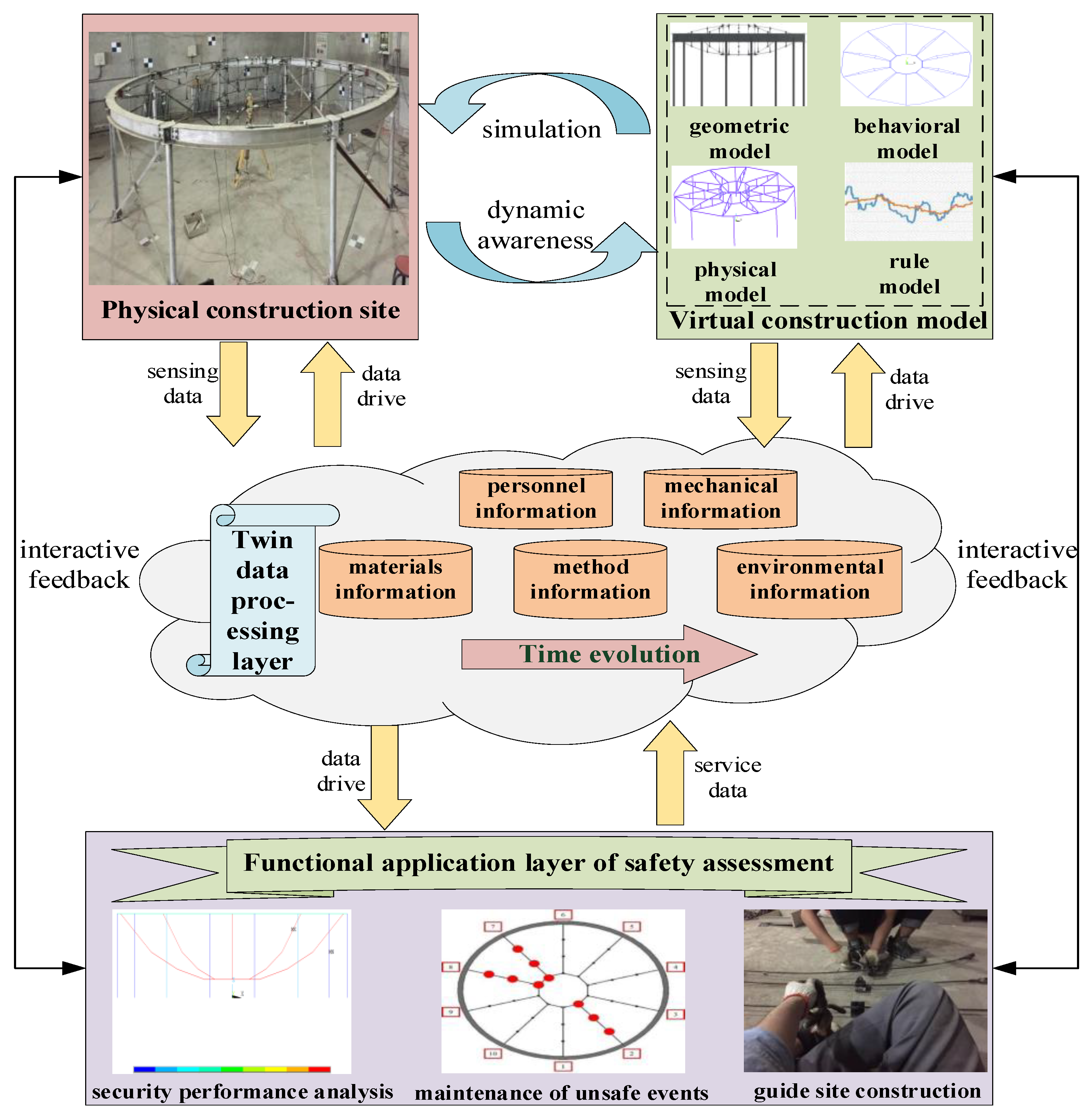
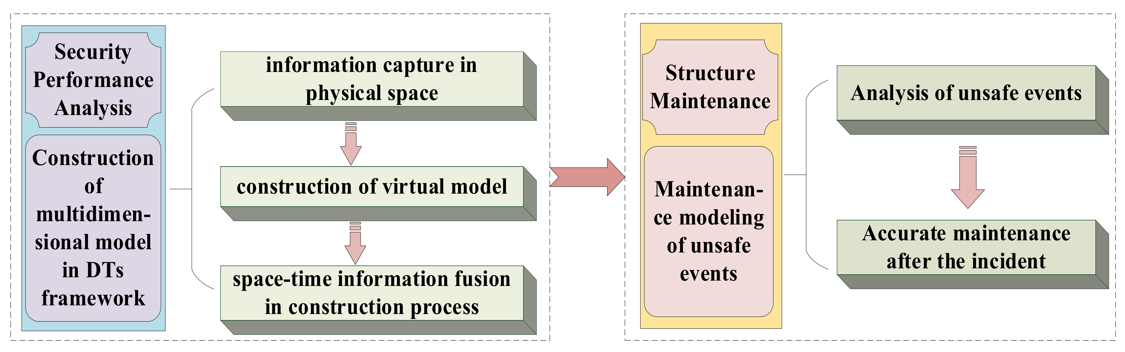
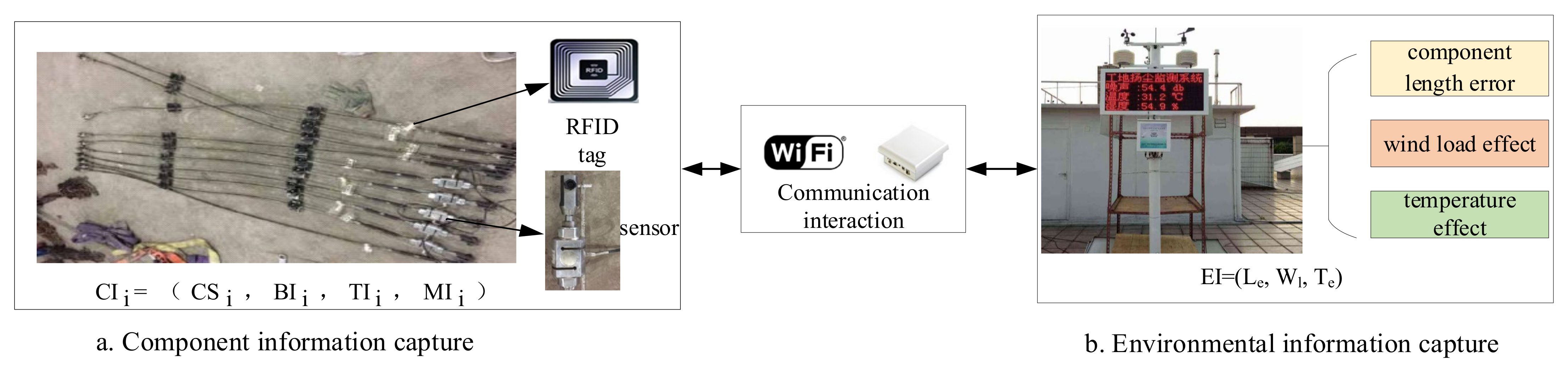
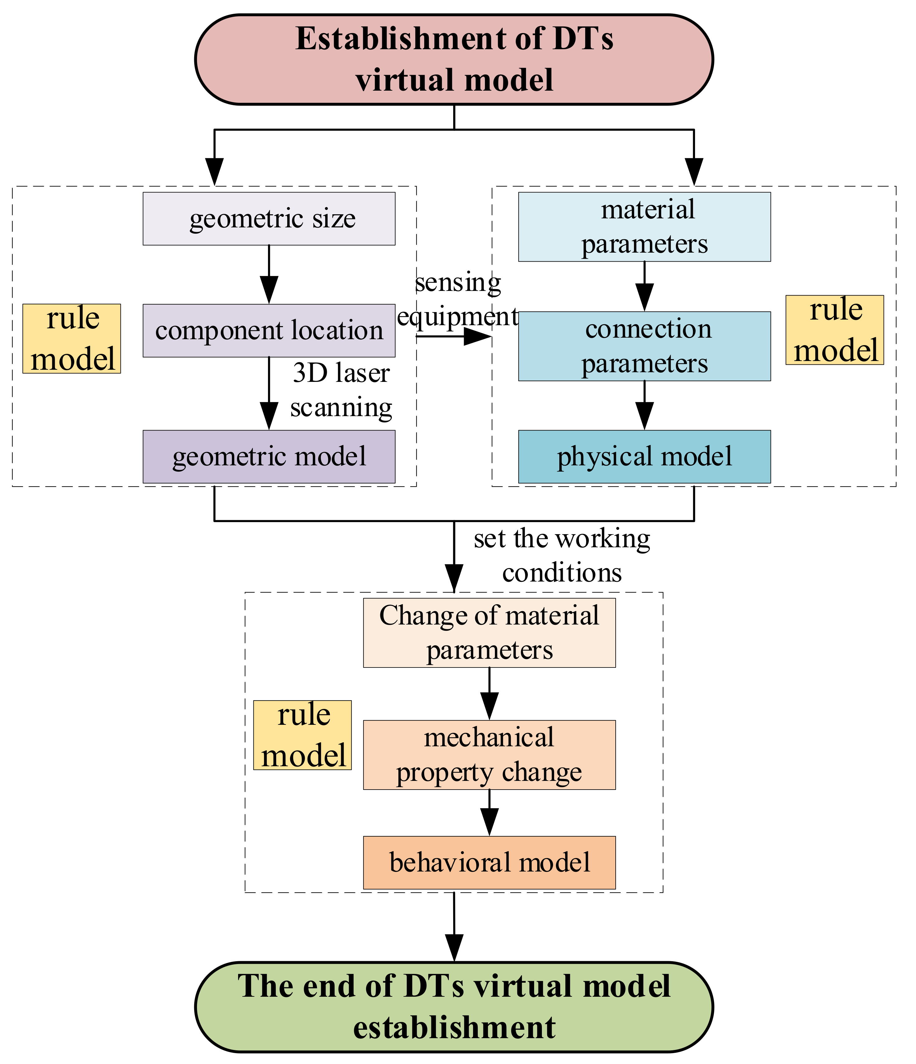
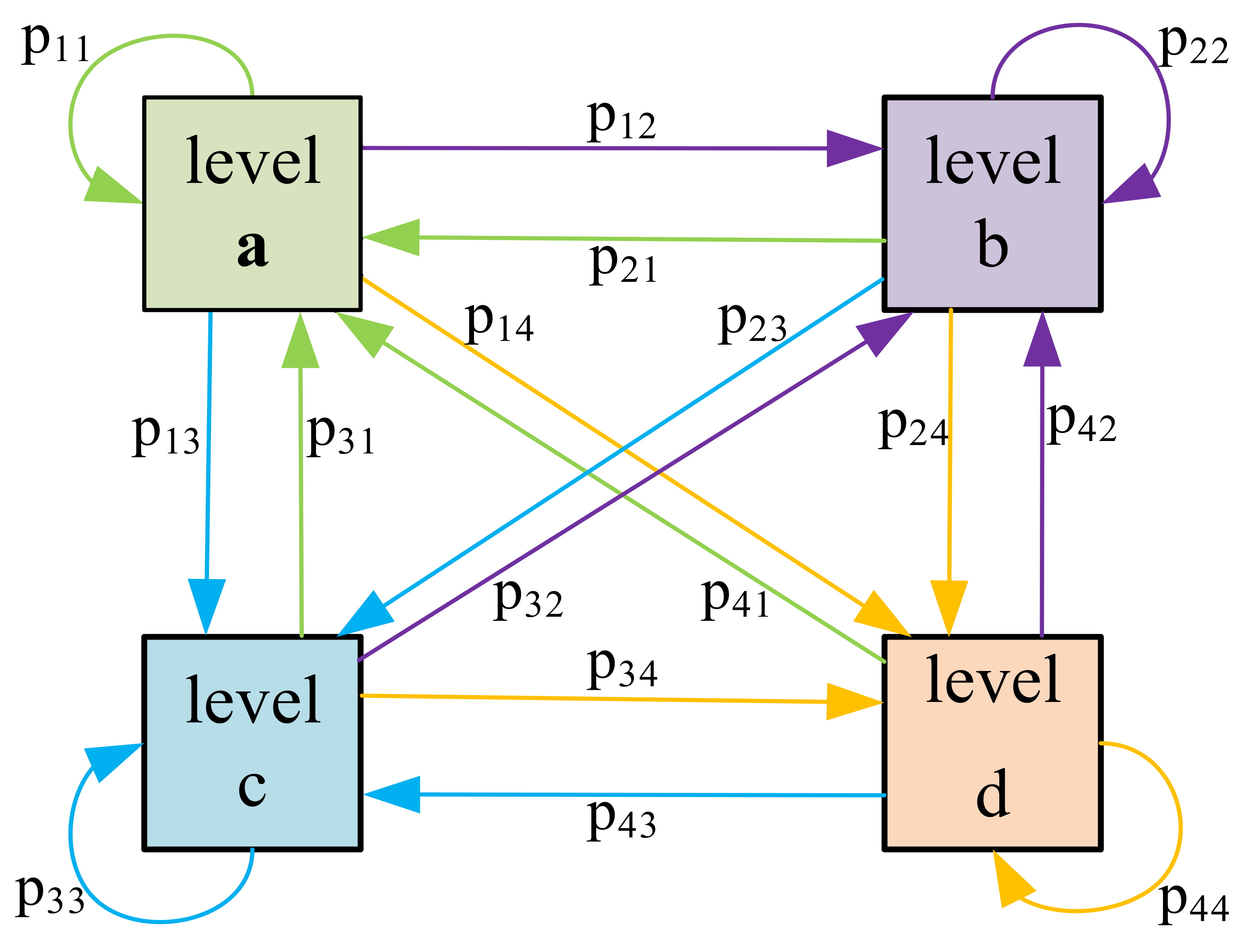
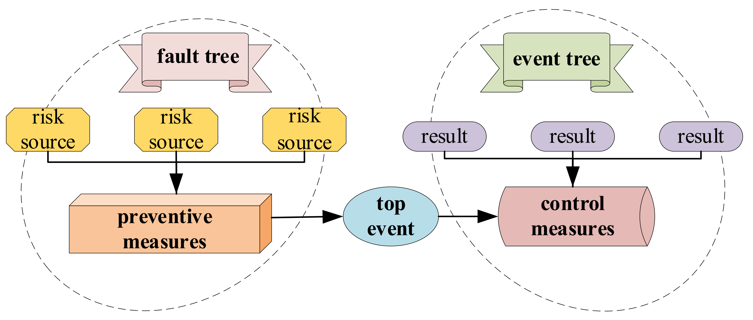
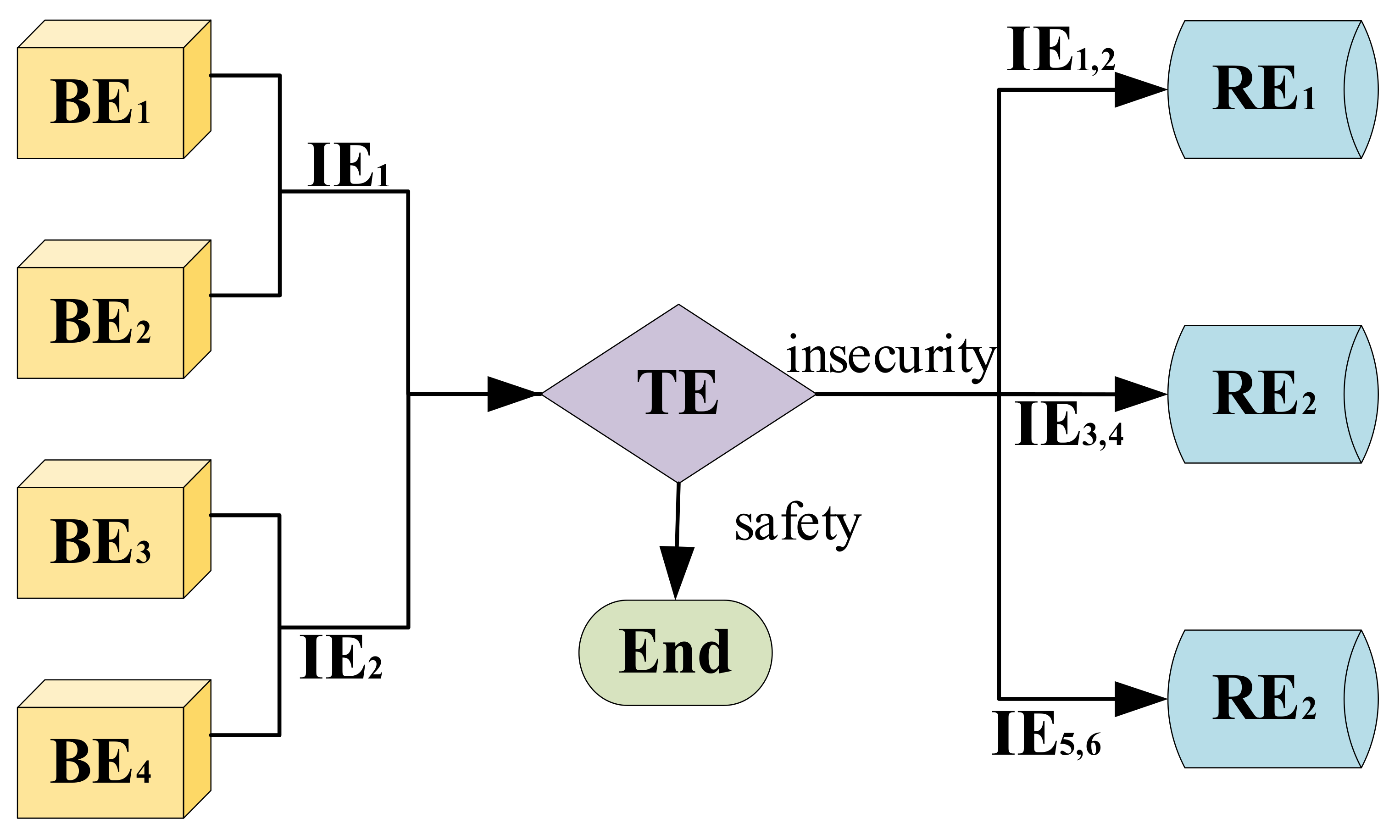
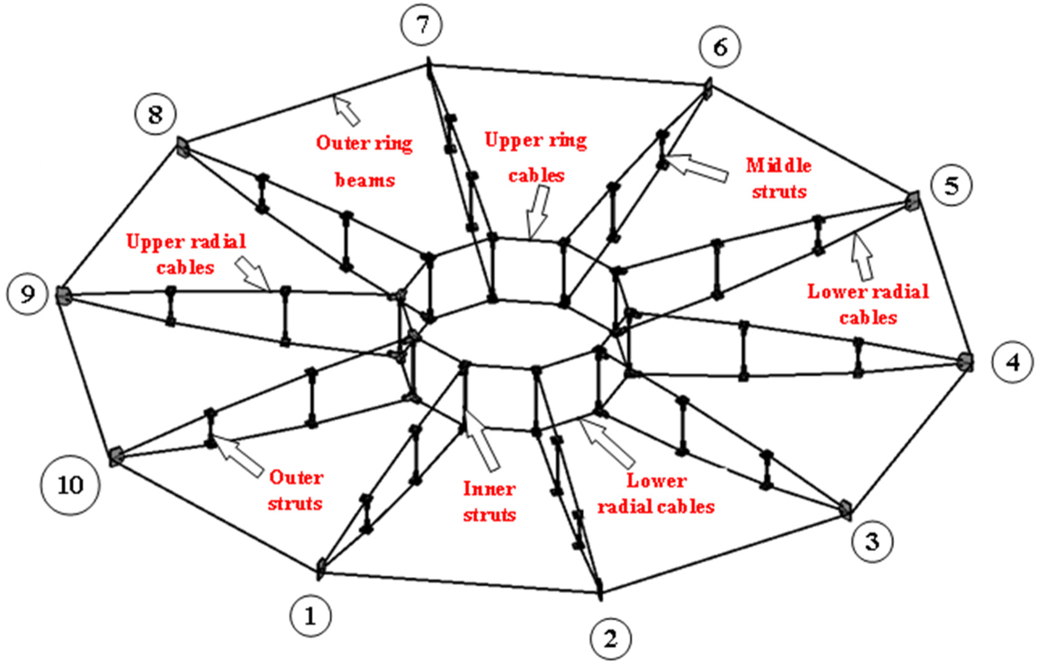
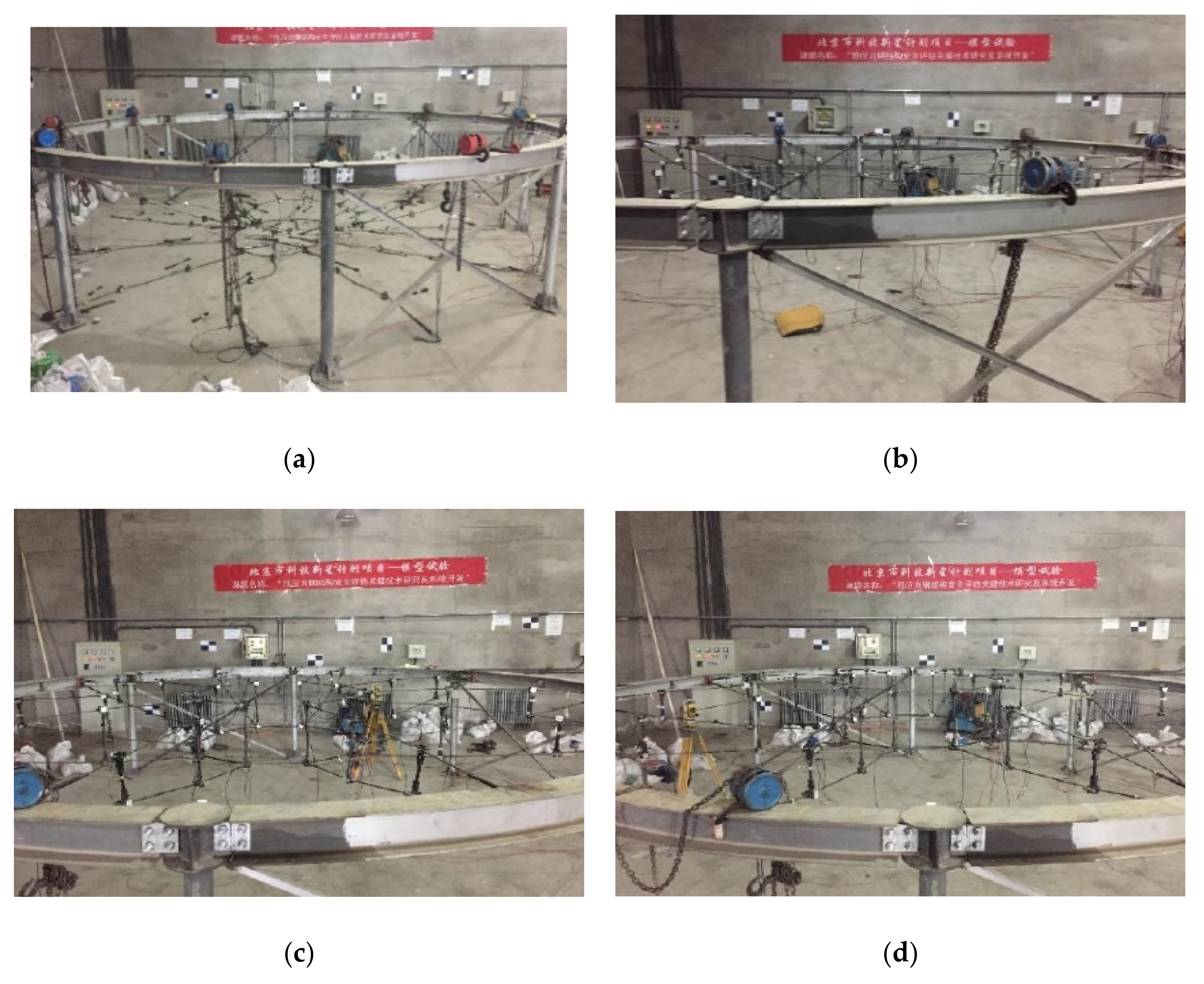
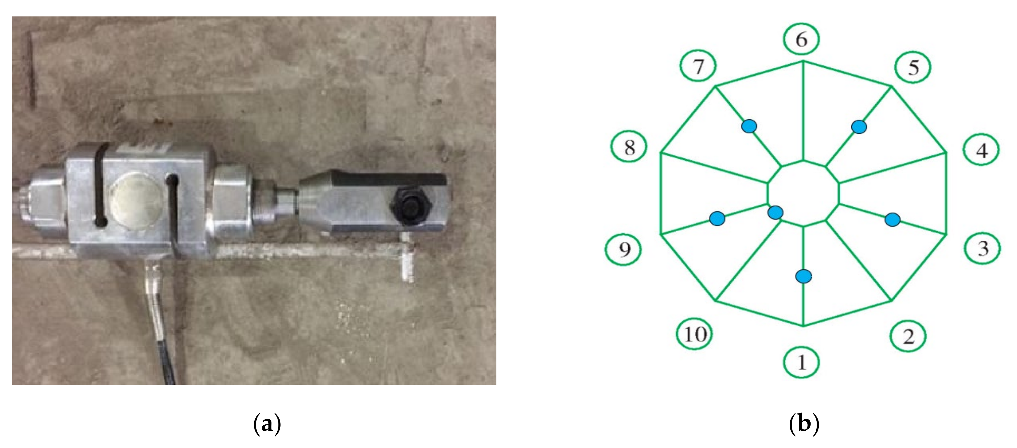
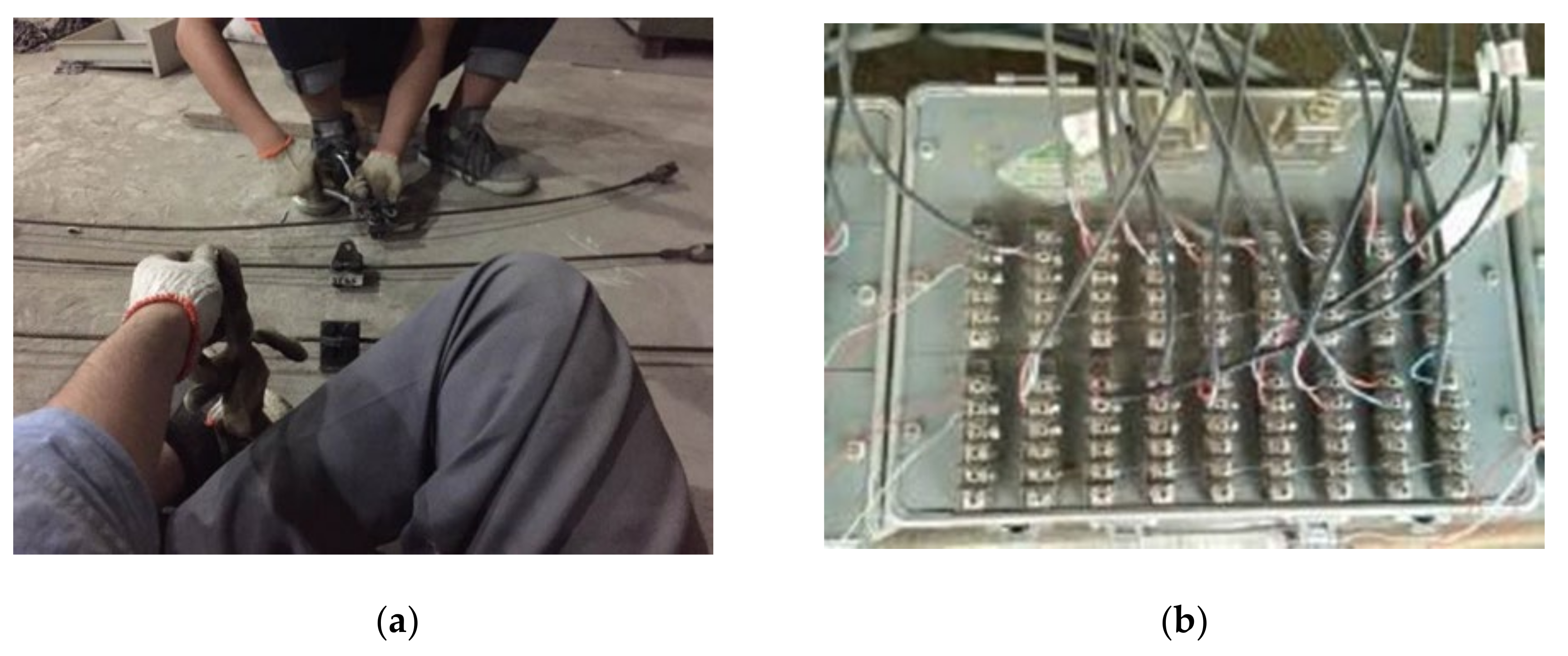
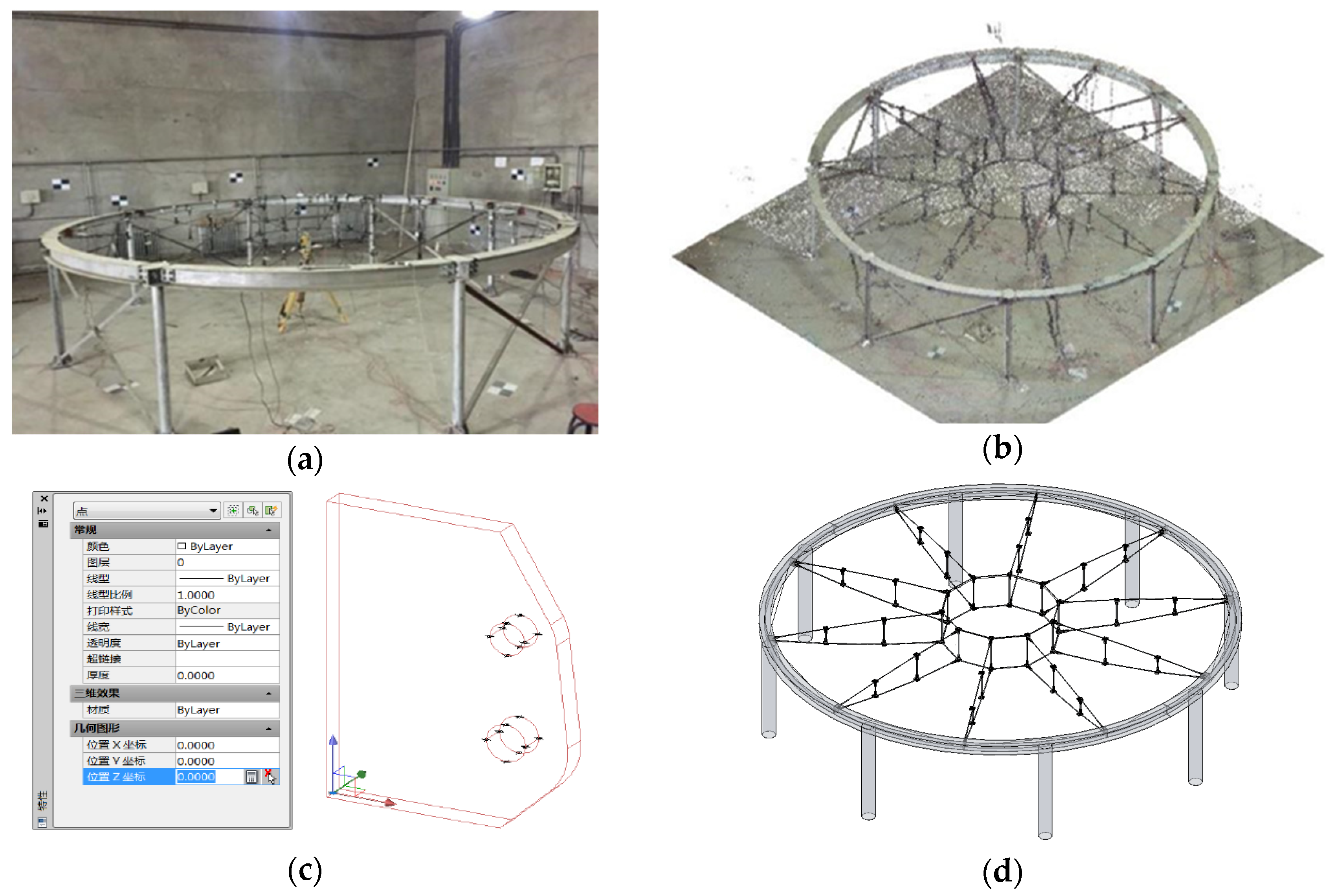
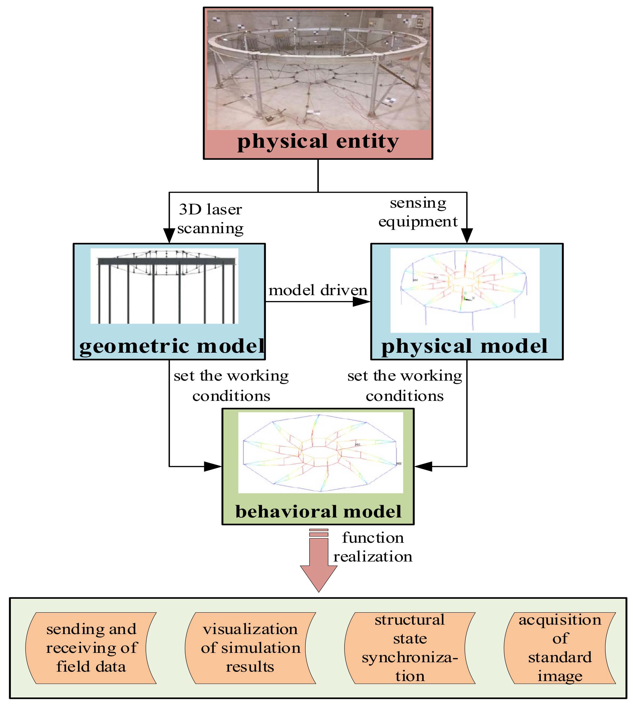
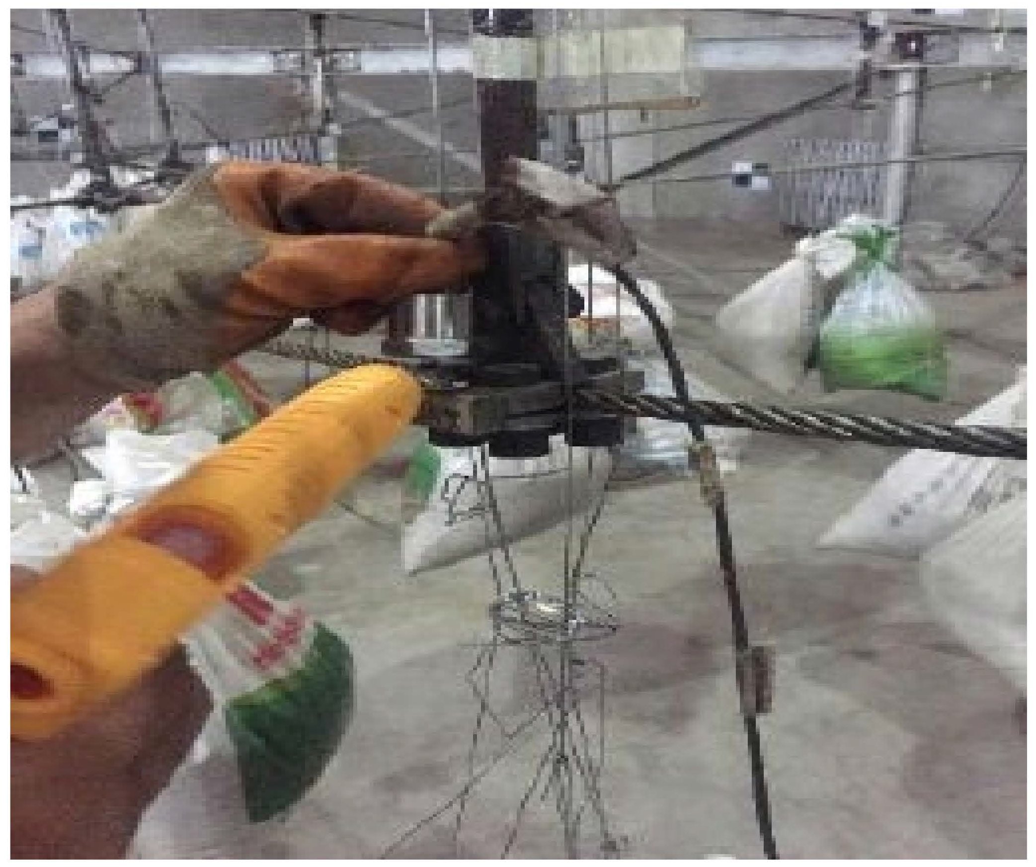
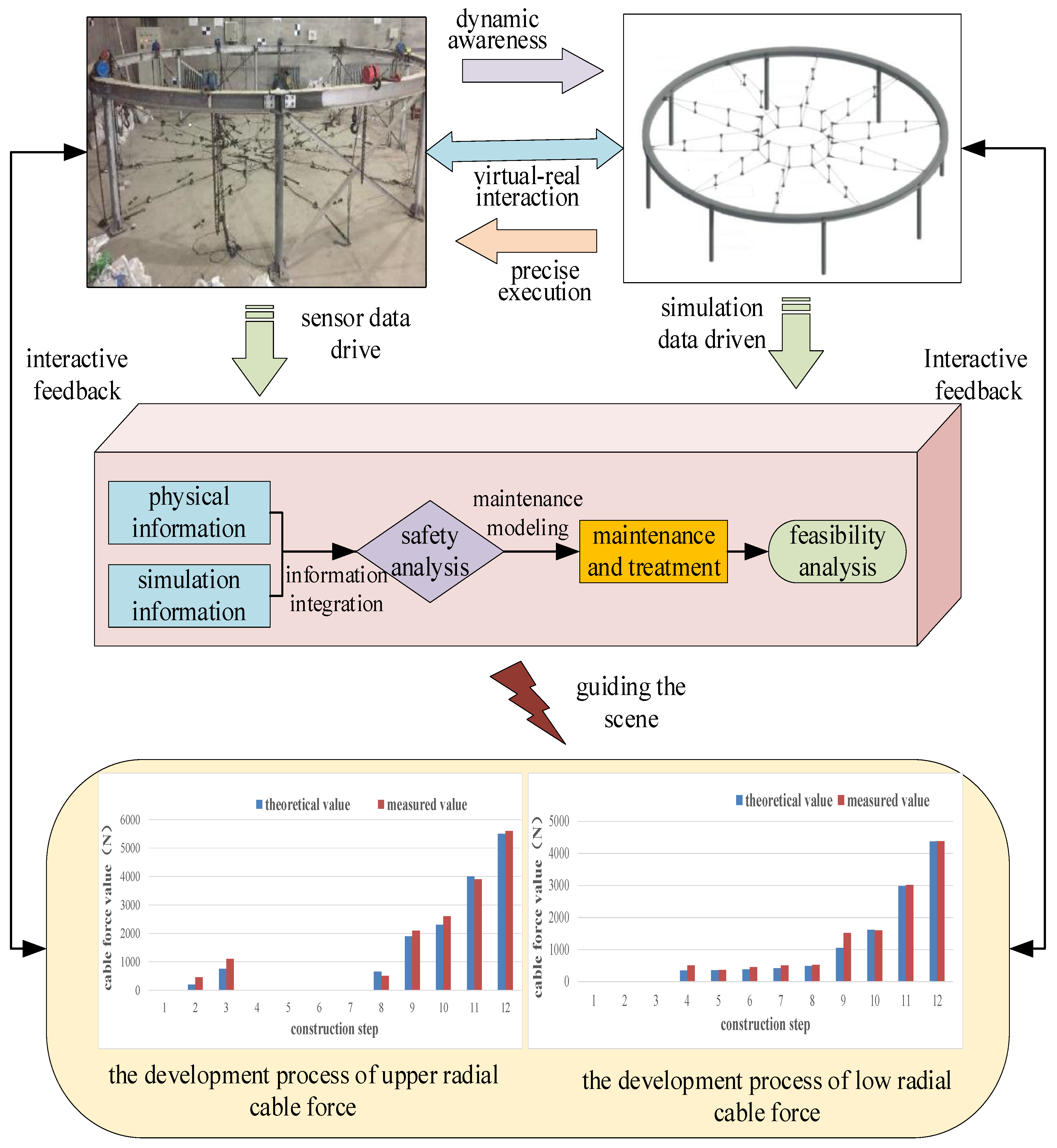
Table 1.
The comparison between the theoretical coordinates and the measured coordinates of the key nodes.
Table 1.
The comparison between the theoretical coordinates and the measured coordinates of the key nodes.
| Key Node | Theoretical Coordinates | Measured Coordinates | Coordinate Difference |
|---|---|---|---|
| Upper radial cable head hole 1 | (−2110.4, 0, −172.6) | (−2111.3, 0.3, −171.4) | (−0.85, 0.3, 1.25) |
| Upper radial cable head hole 2 | (−2116.4, 0, −179.3) | (−2117.4, 0.3, −178.3) | (−0.92, 0.3, 1.00) |
| Upper radial cable head hole 3 | (−2110.5, 0, −184.5) | (−2111.5, 0.3, −183.7) | (−0.91, 0.3, 0.84) |
| Upper radial cable head hole 4 | (−2104.5, 0, −177.8) | (−2105.5, 0.3, −176.7) | (−0.94, 0.3, 1.19) |
| Upper radial cable head hole 5 | (−2110.4, 20, −172.6) | (−2111.3, 20.3, −171.4) | (−0.85, 0.3, 1.25) |
| Upper radial cable head hole 6 | (−2116.4, 20, −179.3) | (−2117.4, 20.4, −178.5) | (−0.92, 0.4, 0.80) |
| Upper radial cable head hole 7 | (−2110.5, 20, −184.5) | (−2111.5, 20.3, −183.7) | (−0.91, 0.3, 0.84) |
| Upper radial cable head hole 8 | (−2104.5, 20, −177.8) | (−2105.7, 20.3, −176.7) | (−1.14, 0.3, 1.19) |
Table 2.
Adjustment of cable section area.
| Member Type | Location | Cross Sectional Area (mm2) |
|---|---|---|
| Radial cable | Upper level | 24.6 |
| Lower level | 33.3 | |
| Ring cable | Upper circle | 24.6 |
| Lower circle | 49.1 | |
| Strut | Outer circle | 62.8 |
| Mid circle | 62.8 | |
| Inner circle | 62.8 | |
| Ring beam | Outer circle | 4300 |
Table 3.
Cable force of each construction step of the structure.
| Upper Radial Cable | Lower Radial Cable | |||
|---|---|---|---|---|
| Theoretical Value (N) | Measured Value (N) | Theoretical Value (N) | Measured Value (N) | |
| Construction step 1 | 0 | 0 | 0 | 0 |
| Construction step 2 | 285 | 372 | 0 | 0 |
| Construction step 3 | 914 | 1062 | 0 | 0 |
| Construction step 4 | 0 | 0 | 356 | 482 |
| Construction step 5 | 0 | 0 | 365 | 363 |
| Construction step 6 | 0 | 0 | 387 | 442 |
| Construction step 7 | 0 | 0 | 427 | 502 |
| Construction step 8 | 603 | 574 | 498 | 518 |
| Construction step 9 | 1985 | 2079 | 1024 | 1482 |
| Construction step 10 | 2387 | 2549 | 1621 | 1612 |
| Construction step 11 | 3964 | 3912 | 2992 | 3010 |
| Construction step 12 | 5503 | 5587 | 4374 | 4383 |
Publisher’s Note: MDPI stays neutral with regard to jurisdictional claims in published maps and institutional affiliations. |
© 2021 by the authors. Licensee MDPI, Basel, Switzerland. This article is an open access article distributed under the terms and conditions of the Creative Commons Attribution (CC BY) license (https://creativecommons.org/licenses/by/4.0/).
Share and Cite
MDPI and ACS Style
Liu, Z.; Shi, G.; Jiao, Z.; Zhao, L. Intelligent Safety Assessment of Prestressed Steel Structures Based on Digital Twins. Symmetry 2021, 13, 1927. https://0-doi-org.brum.beds.ac.uk/10.3390/sym13101927
AMA Style
Liu Z, Shi G, Jiao Z, Zhao L. Intelligent Safety Assessment of Prestressed Steel Structures Based on Digital Twins. Symmetry. 2021; 13(10):1927. https://0-doi-org.brum.beds.ac.uk/10.3390/sym13101927
Chicago/Turabian StyleLiu, Zhansheng, Guoliang Shi, Zedong Jiao, and Linlin Zhao. 2021. "Intelligent Safety Assessment of Prestressed Steel Structures Based on Digital Twins" Symmetry 13, no. 10: 1927. https://0-doi-org.brum.beds.ac.uk/10.3390/sym13101927
Note that from the first issue of 2016, this journal uses article numbers instead of page numbers. See further details here.