
A Driver and Control Method for Primary Stator Discontinuous Segmented-PMLSM


School of Electrical Engineering and Automation, Harbin Institute of Technology, Harbin 150000, China
*
Author to whom correspondence should be addressed.
Symmetry 2021, 13(11), 2216; https://0-doi-org.brum.beds.ac.uk/10.3390/sym13112216
Submission received: 26 October 2021
/
Revised: 11 November 2021
/
Accepted: 12 November 2021
/
Published: 19 November 2021
(This article belongs to the Special Issue Research on Motor and Special Electromagnetic Device of Symmetry)
Abstract
:In recent years, with the development of the permanent magnet linear synchronous motor (PMLSM), the application of PMLSM has not been limited only to the high-end equipment field; the primary stator discontinuous segmented-PMLSM (DSPMLSM), which consists of multiple primary stators and one mover, has also been applied in long-distance transportation systems, such as electromagnetic launch, high precision material transport, etc. Compared with the symmetry phase parameters of conventional PMLSM, the stationary electrical parameters vary when the mover enters and leaves the primary stators (the inter-segment region). At the same time, due to the sectional power supply, there will be primary suction or pulling force when the mover enters and exits the inter-segment region, which will lead to large thrust fluctuation and result in lager position error. This paper proposed a related drive and control strategy about the DSPMLSM system, which improved the position tracking accuracy during the full range of DSPMLSM. First, the parameter variation between stator segments has been analyzed through finite element simulation of DSPMLSM. Then, a double closed-loop series control structure of position-current is designed, in which a PI-Lead controller was adopted for the position loop and a PI controller was adopted for the current loop. In order to improve the position tracking accuracy of DSPMLSM, a thrust fluctuation extended state observer (TFESO) was adopted to observe and compensate the complex thrust disturbances such as cogging force, friction and other unmodeled thrust fluctuation. At last, the DSPMLSM experimental stage was established, and the experimental results show that the proposed driver and control theory can effectively improve the position tracking accuracy of the whole stroke of DSPMLSM.
1. Introduction
PMLSM has the advantages of high efficiency and high thrust density, and it has been widely used in high-end equipment fields [1], such as mask aligners, high-end CNC machine tools, etc. In recent years, with the gradual deepening of research, PMLSM has been slowly applied in the fields of rail transit, electromagnetic launch, vertical lifting and long-distance material transportation [2,3]. The application of PMLSM in long distance material conveying systems can minimize transmission error, improve material conveying speed and accuracy, and further improve production efficiency. However, in long-stroke material conveying systems, DSPMLSM is generally needed, because DSPMLSM is superior to single-stage PMLSM in manufacturing, maintenance, energy saving, cost, etc. DSPMLSM includes more than one primary stator, and its mover contains magnetic steel. There are two possible situations in the process of mover moving: (1) the mover only has overlapping area with a single primary stator; (2) the mover has overlapping area with two primary stators. In these two cases, the electrical parameters of the stators are different, and at the same time, there is bound to be large thrust fluctuation during the entry and exit of the primary stators, and the large thrust fluctuation will lead to large position error. Therefore, the appropriate driver and control strategy of DSPMLSM needs to be studied to improve the position tracking precision.
Many scholars have studied the design and drive control method of DSPMLSM. Literature [4] has overviewed the drive method, loss optimization, inverter capacity and primary length design of SPMLSM, and put forward some ideas according to the characteristics of DSPMLSM, such as master–slave primary current command drive strategy, primary stators loss optimal control of SPMLSM, etc. Literature [5,6] analyzes the variation of the end cogging force of DSPMLSM with the position by the finite element method. The simulation results show that when the Mover enters and exits the primary stator edge, there will be a large end cogging force disturbance, the transverse end cogging force plus the normal suction force will bring a large thrust fluctuation to the mover. The literature further optimizes the end slot structure and permanent magnet shape to reduce the thrust fluctuation in the inter-segment region. In reference [7], a cogging force testing device with a rigid connection of two movers was designed for DSPMLSM, which controls one mover to drag the other mover at a constant speed and drags back and forth in both directions to counteract the influence of friction. The relationship between the cogging force and position was obtained through such testing, and then it was used as feedforward compensation to thrust fluctuation.
Literature [8,9,10] theoretically analyzed the variation law of electrical parameters in the inter-segment region and established the corresponding DSPMLSM model. Literature [8] obtained the variation law of incremental self-inductance and mutual inductance of segmented permanent magnet motor in the inter-segment region by using energy perturbation method and analyzed the influence law of different stator and mover length ratios on the inductance between segments. Literature [9] studies the variation law of d-q axis coupling inductance of concentrated winding for continuous segmented-PMLSM (CSPMLSM), a new measure method for d-q axis coupling inductance was proposed, and the influence of three-phase asymmetry on the d-q axis coupling inductance of CSPMLSM was further studied. In [10], the asymmetry and saturated effects of three-phase inductance are studied analytically, and the two-dimensional inductance lookup table was established by converting the double three-phase current into an α β coordinate system. By introducing sig-mod function, the flux linkage and back electromotive force in the inter-segment region were accurately described, and the phase space model of double three-phase CSPMLSM was established by using these electrical parameters.
As for the driving strategy of DSPMLSM, the literature [11] regards the thrust coefficient, back EMF coefficient and self-inductance of the motor as linear changes in the transition stage in the inter-segment region and makes feedforward compensation for the cogging force at the edge and in the segments, thus establishing the simulation model of segmented linear motor system. The reference [12] has implemented experiments based on the theoretical analysis and simulation model of reference [11]; the experiment adopted a double closed-loop series control structure of velocity-current (Two PI controller). Due to the parameter variation between DSPMLSM segments and the disturbance of cogging force, the speed tracking accuracy is easily affected by parameter variation disturbance. As for collaborative control of current between adjacent primary stators, to reduce the current difference between different segments, reference [13] adopted the current synchronization tracking strategy between segmented stators, and the improved current predictive control method was combined to improve the current regulation speed and realize the current synchronization control between stator segments. Simulation and experimental results show that the improved method can effectively suppress the thrust fluctuation between segments of segmented linear motor.
Literature [14] used finite element simulation to analyze the asymmetry of back EMF, the cogging force and the end cogging thrust existing in DSPMLSM. Aiming at reducing the thrust fluctuation in the inter-segment region, it is proposed to calculate the phase current instruction by using the back EMF and thrust reference. Simulation and experiment results verified that this method is more accurate than d-q axis rotation coordinate system control, but this method needs to achieve the back EMF value in real time, which is difficult to implement for DSPMLSM. Literature [15] investigated the characteristics of the PMLSM applied in ropeless elevators, including d-q axis inductances, PM flux linkage, thrust force, lowering the copper loss and thrust force ripple, and proposed a new switching method of primary sections which makes the excited primaries decrease to two sections in most time ranges compared with three sections in the commonly used method. Literature [16] divided the moving stroke of the SW-PMLSM into five zones according to the position of the secondary, and the implementations for both control methods are investigated in the five zones; however, this paper only investigated the current control of SW-PMLSM.
Literature [17] studied the sensorless control method of segmented PMLSM and corrected the current controller parameters online according to the calibrated flux linkage and inductance parameters, but this literature only considered the design of the speed controller. Literature [18] proposed a SW-PMLSM high-efficiency V/f control method, and this method combines the advantages of traditional V/f control and field-oriented control; the advantage of the proposed method is that it does not need to install a position sensor and can realize simple and high-performance motor drive, but the experimental results show that there are larger speed fluctuations. In all, from the literature in recent years, there is little research work about position controller design of DSPMLSM, and this paper proposed a driver and control method for DSPMLSM.
This paper was organized as follows. In Section 2, the characteristics of electrical parameters in the inter-segment region of DSPMLSM were analyzed through finite element simulation. In Section 3, a driver strategy was proposed for DSPMLSM. In Section 4, the PI-Lead controller and TFESO for DSPMLSM was designed. In Section 5, the experimental stage was established, and the proposed scheme was verified by experimental results. Finally, the conclusion was given in Section 6.
2. Electrical Parameters Characteristics Analysis of DSPMLSM
The finite element model of DSPMLSM was built in ANSYS, as shown in Figure 1. The mover is the secondary magnetic poles, and the coreless winding is the primary stators. Pole–slot ratio of DSPMLSM is 10 poles and 12 slots, the pole distance is 31.25 mm and the air gap is 1.5 mm.
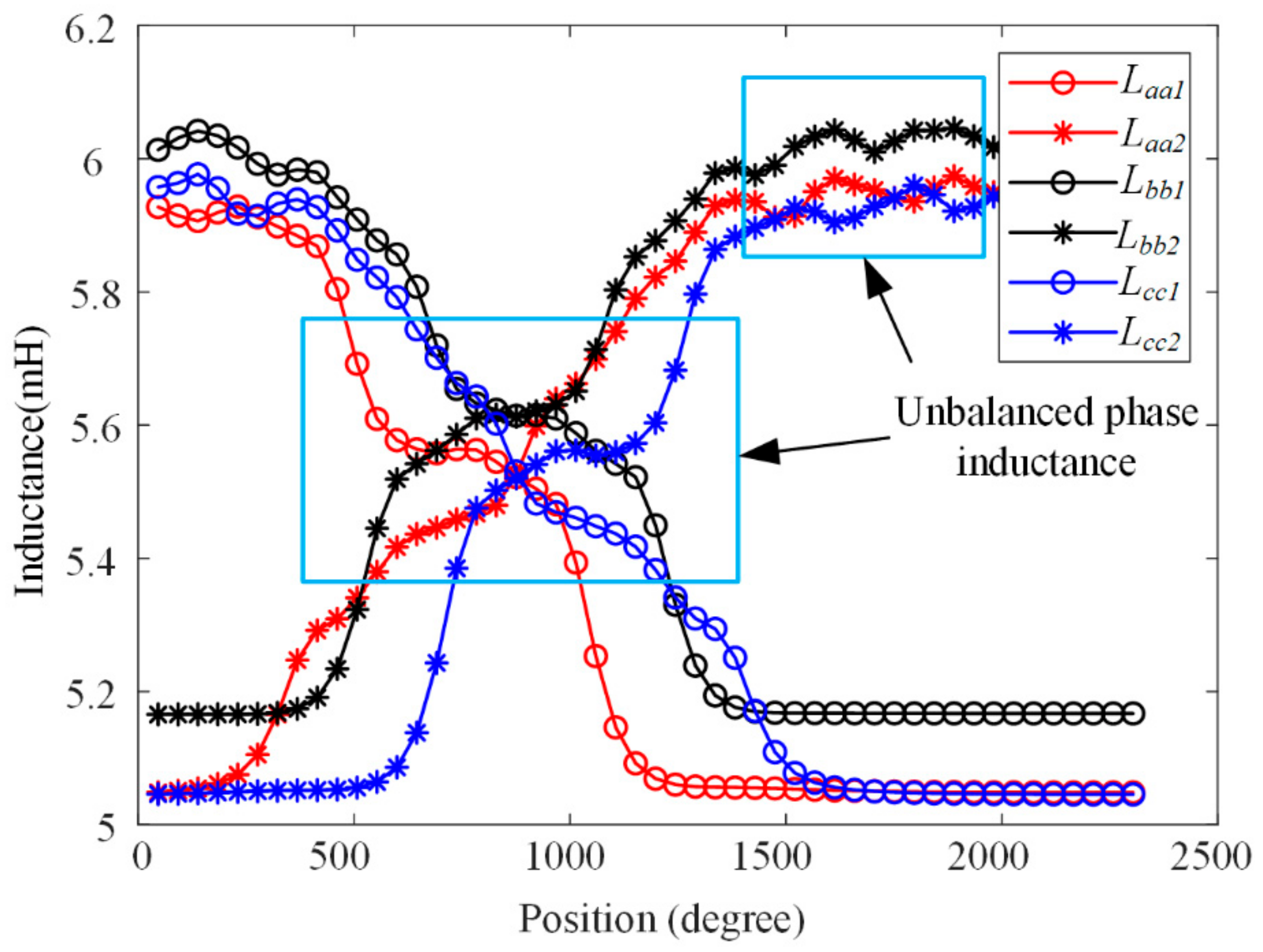
Through the finite element analysis, the self-inductance curves of the two primary stators were shown in Figure 2. The asymmetry of the three-phase self-inductance is obvious, and the asymmetry of the phase inductance is more obvious when the mover enters and leaves the primary stator.
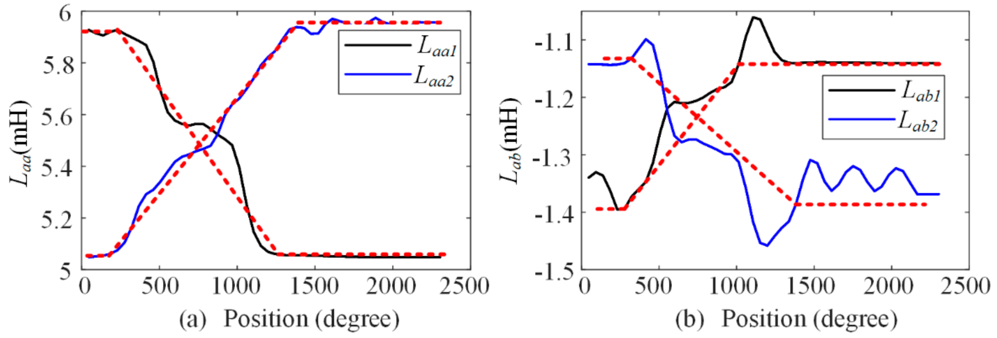
In order to analyze the variation law of self-inductance and the mutual inductance of phase inductance, the self-inductance and mutual inductance curves of phase A were extracted as shown in Figure 3. As seen from the waveforms of self-inductance in Figure 3a and the mutual inductance in Figure 3b, when the mover is in the inter-segment region, both self-inductance and mutual inductance vary linearly. We can explain the linear variation law through the inductance formula L = N2λ, where N is the winding turns, and λ is the permeability related to the overlapping area of the primary stators and the mover; due to the linear variation of the overlapping area, the inductance varies linearly in the inter-segment region.
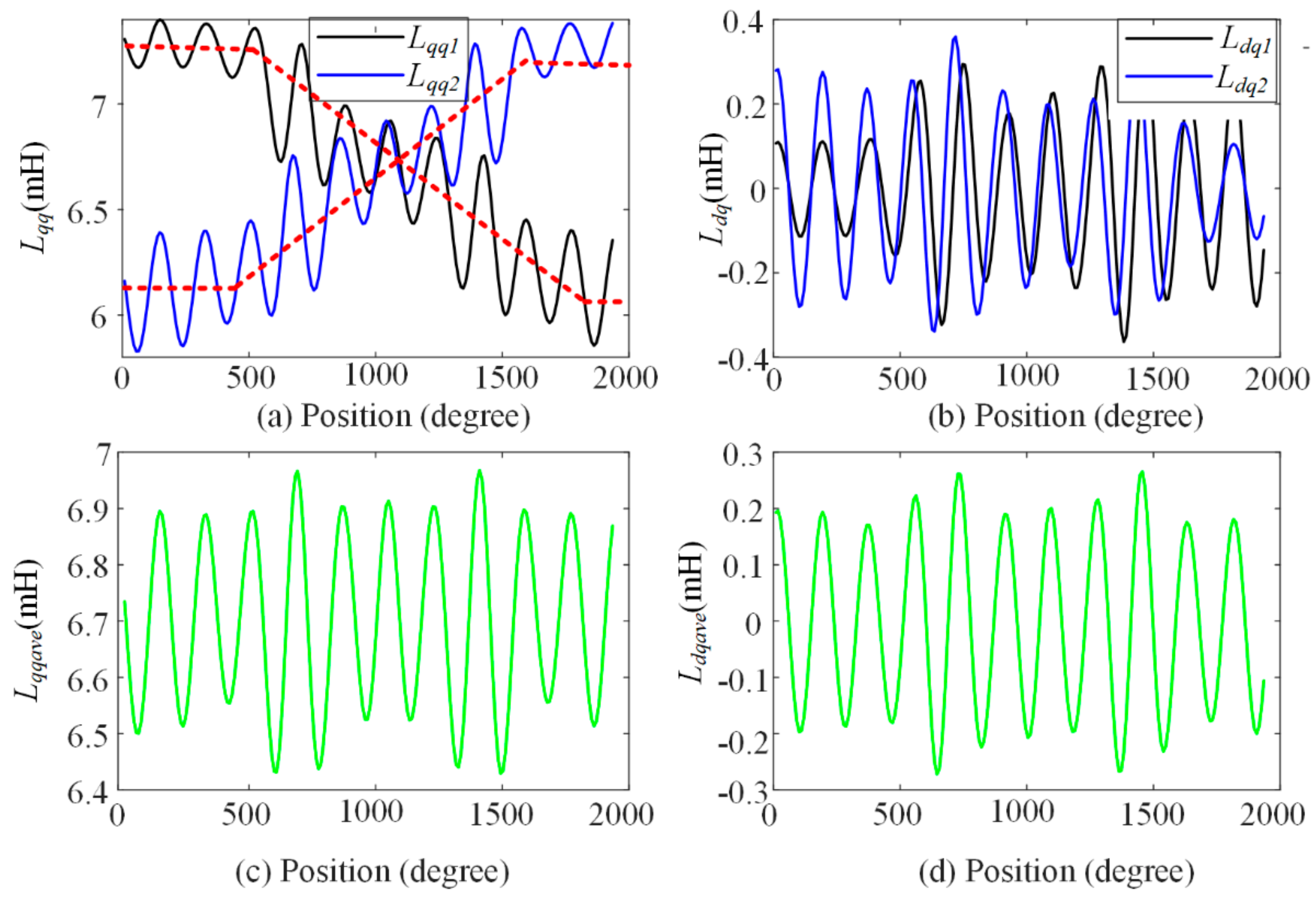
After inductance data post−processing, the d−q axis self−inductance and mutual inductance of two adjacent stators were achieved as shown in Figure 4 It can be seen from the waveform that the d−q axis self-inductance and mutual inductance of the single stator both have the second harmonic component caused by the asymmetry phase inductance. The amplitude of the second harmonic component accounts for about 8% of the total q axis inductance value, and the second harmonic component increases obviously when the mover is in the inter−segment region. In order to further study the initial phase angle of the second harmonic component in d−q axis inductance, Lqqave and Ldqave were obtained by averaging the two primary stator’s q axis self−inductance and d−q axis mutual inductance, as shown in Figure 4c,d. It can be seen that the initial harmonic phase angles in d−q axis inductance are basically equal; the influence of the second harmonic inductance cannot cancel out each other for two adjacent stators. Therefore, it will result in thrust fluctuation in the inter−segment region.
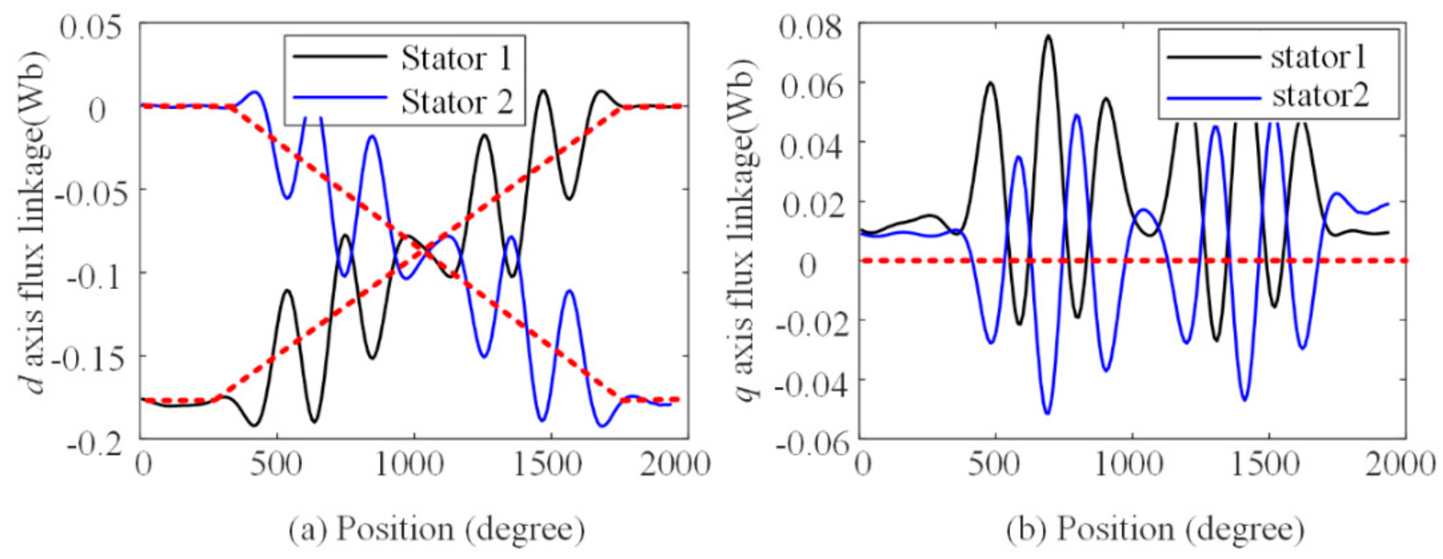
The d−q axis flux linkage was shown in Figure 5. The d axis flux linkage (permanent magnet flux linkage) waveform in the inter−segment region was shown in Figure 5a. The variation law of the flux linkage is similar to the d−q axis inductance, which is changed linearly in the inter−segment region. It can be explained that the overlapping area of the mover’s permanent magnet and primary stator winding changes linearly when the mover moves in constant velocity. From the waveform, the d axis flux linkage contains a first harmonic component with large amplitude, and the phase angle difference of d axis flux linkage harmonic is 180˚. The q axis flux linkage contains the second harmonic component in the inter-segment region, which leads to the thrust fluctuation.
3. Driver Strategy of DSPMLSM
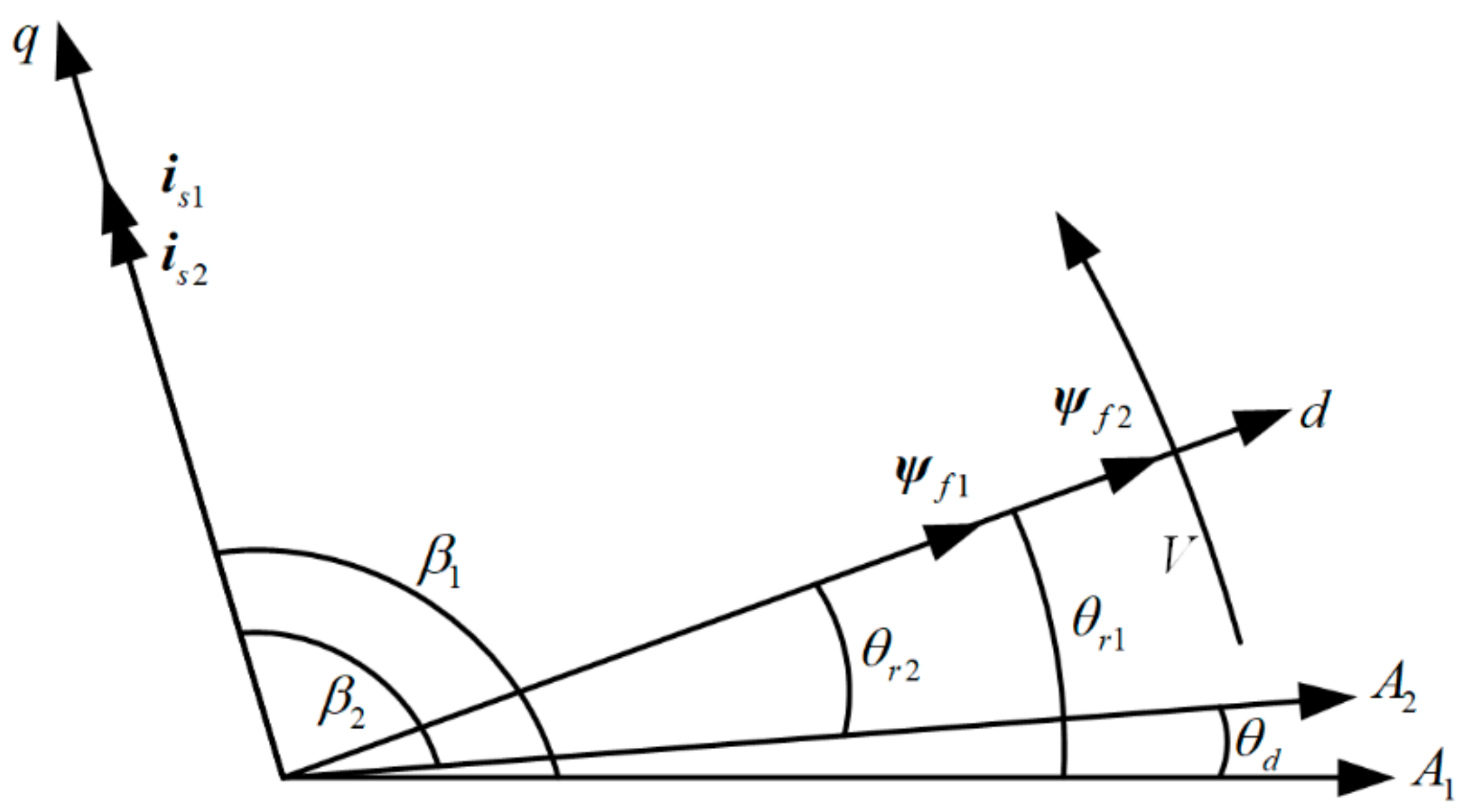
The vector diagram of the DSPMLSM is shown in Figure 6, in which the d-q rotation coordinate system was assumed to be located on the mover, the coordinate axes A1 and A2 represent the spatial positions of the A−phase winding axes of two adjacent segmented primary stators, and θd is the gap electrical angle of the adjacent two primary lengths. If the primary lengths add sectional air gap lengths of an integral multiple of 2τ (τ is the pole distance), the positions of A1 and A2 will coincide in the d−q rotation coordinate system. β1 and β2 are the angles between the d axis of the mover and the adjacent two primary stators’ A phase axis, respectively.
According to the vector diagram, the expression of the current vector of the adjacent primary stators were shown in Equation (1).
In order to achieve a smooth transition between the two primary stators, it is necessary to adjust the phase of the second primary current is2 to lag behind the phase β1 of the first primary current is1 (satisfy that β2 = β1 −θd), so that the thrust angles of the two primary stators are equal. The corresponding thrust formula is shown in Equation (2).
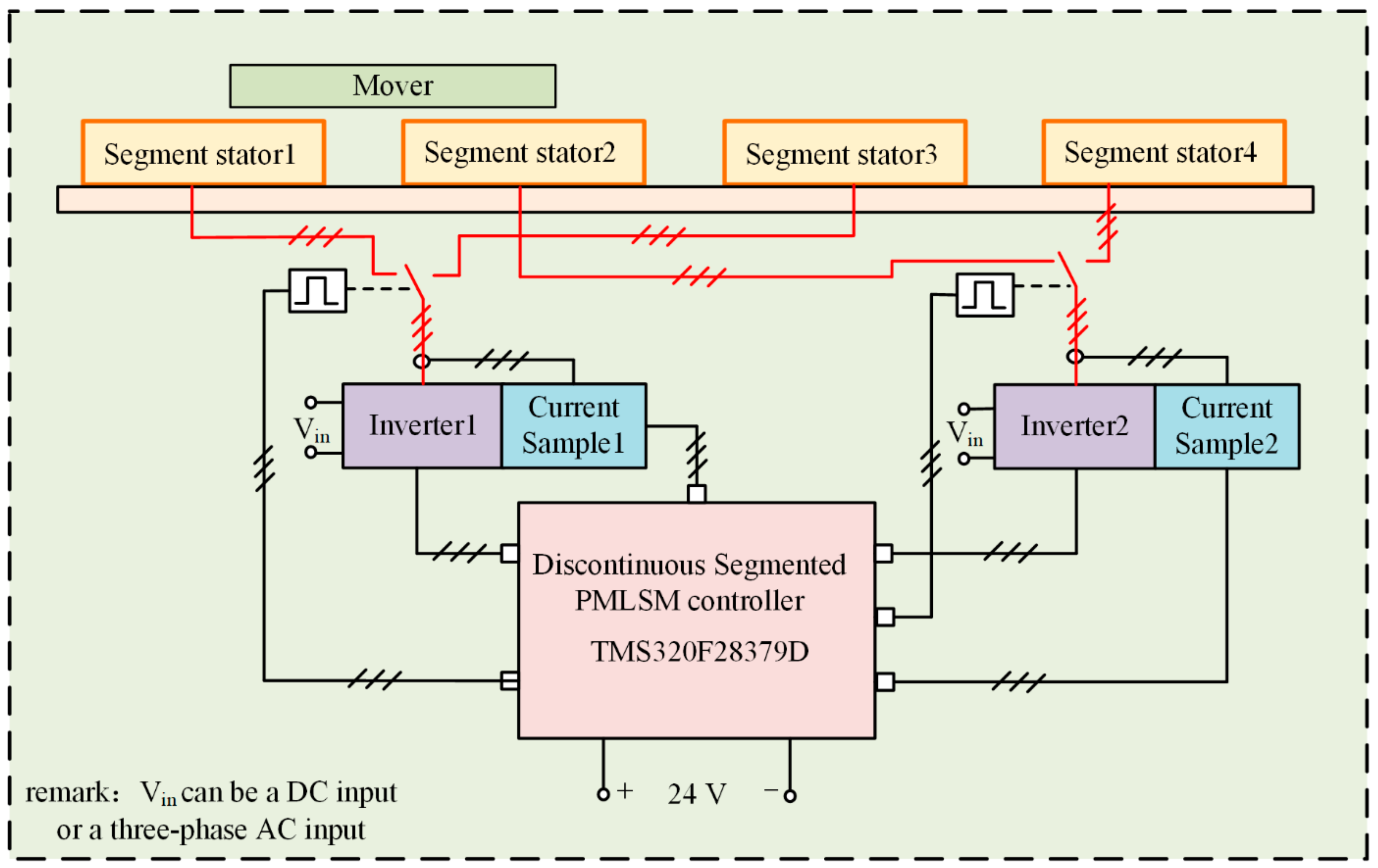
The block diagram of the drive and control system for DSPMLSM was shown in Figure 7, which includes two drivers, two sampling modules and one controller. The DSPMLSM consists of four primary stators and one mover, in which 1/3 primary stators share the same driver and sampling module, while 2/4 primary stators share the other driver and sampling module, and the winding and driver are switched by solid state relays.
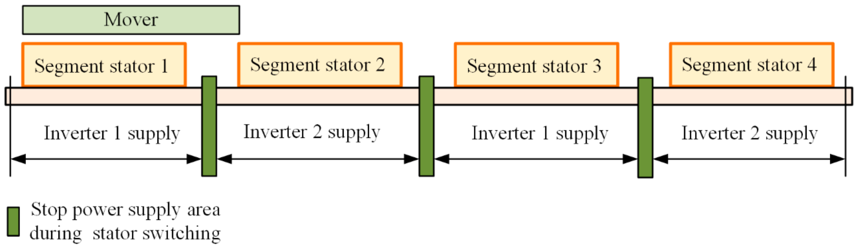
The strategy power supply switch for primary stators was shown in Figure 8. First, according to the position of the mover, it is judged whether the solid-state relays act to realize the connection and disconnection between the primary winding and the inverter. At the same time, in order to avoid circulation between the two primary stators corresponding to the same inverter, a power supply stopping area (green area) was set during the primary stator switching process. In this area, the solid-state relays of the two primary stators participating in the switching are all disconnected, and the corresponding inverter current command is zero.
4. Design of Position Controller and Thrust Fluctuation Observer for DSPMLSM
In reference [12], the velocity-current double closed-loop control strategy is adopted to drive and control DSPMLSM. In order to further improve the position tracking accuracy of DSPMLSM, this paper adopted the position-current double closed-loop control, in which the position loop adopts a PI-Lead controller, and the current loop adopts a PI controller. The thrust fluctuation was compensated by adding a thrust fluctuation observer.
4.1. Design of PI-Lead Controller for DSPMLSM
First, the mechanical model of the DSPMLSM was established. The control of the DSPMLSM can be approximated as a double integral, and it can be expressed as Equation (3), where kf is the thrust coefficient of the DSPMLSM and M is the mass of the mover.
Carry out a Laplace transform on Equation (3), and the position-current transfer function was achieved as shown in Equation (4), where m = M/kf.
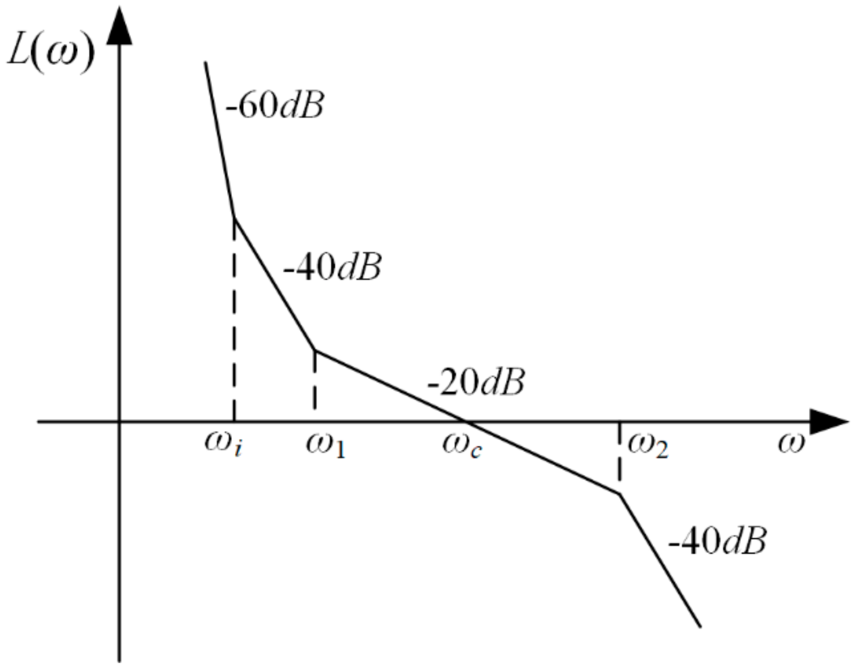
PI-Lead controller consists of a PI controller with a lead compensator. Its transfer function is shown in Equation (5), where ωi is the corner frequency of the PI controller, and ω1 and ω2 are the lead compensator corner frequency.
Combined with the DSPMLSM model, the PI-Lead controller was added to obtain the open-loop transfer function of the system as shown in Equation (6). According to the expected system characteristics, the relationship between several corner frequencies of the controller and the cutoff frequency ωc of the open-loop system should satisfy ωi < ω1 < ωc < ω2, thus the bode diagram of the open-loop system can be obtained as shown in Figure 9.
The mass of the mover is M = 14 kg, the thrust coefficient is kf = 108.2 N/A and the designed integrator corner frequency is fi = 10 Hz. The bandwidth of intermediate frequency h = 16, and the cutoff frequency fc = 40 Hz. The two corner frequencies of the lead compensator can be obtained by Equation (7).
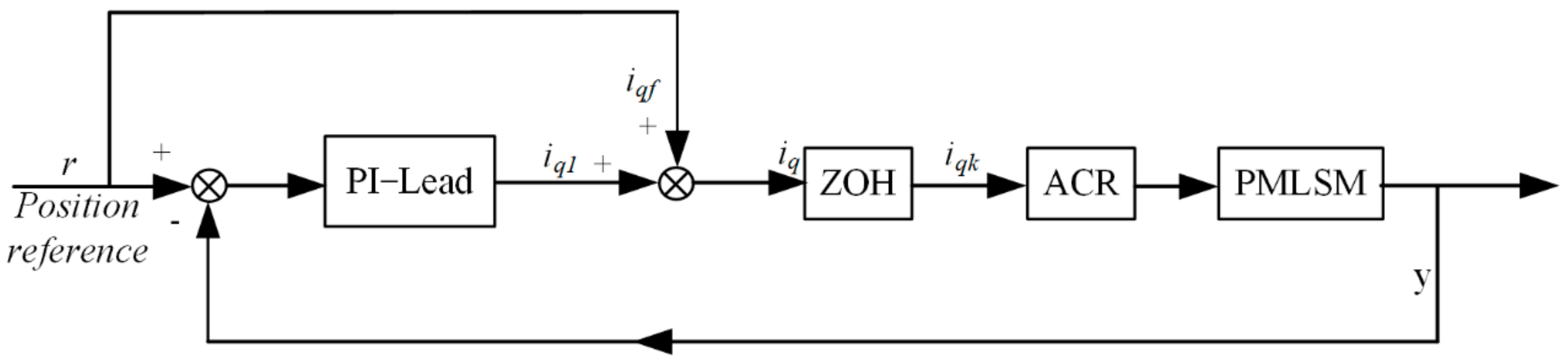
The inverter and other links are regarded as proportional links with a gain of 1, and the block diagram of the PI-Lead controller and acceleration feedforward control system can be further drawn as shown in Figure 10, where r is the position reference.
4.2. TFESO Design
ESO regards all system disturbances as concentrated disturbances and expands them into a new state variable. It does not depend on the specific mathematical model of disturbances and does not need to directly measure its effects. This method is simpler and more practical in suppressing system disturbances [19]. This paper adopted TFESO to observe the thrust fluctuation of DSPMLSM. The following section is about the design principle of thrust fluctuation TFESO.
First, the mechanical model of DSPMLSM considering thrust fluctuation was shown in Equation (8), where Fq was concentrated thrust disturbance, including friction f, cogging force Fc and other unmodeled disturbance forces ξ f. In Equation (8), x is the position of the mover, v is the velocity of mover, kt is the thrust coefficient of single stator and iq is the q axis current.
By expanding the thrust fluctuation component into a new state variable of the system and considering the derivative in terms of thrust fluctuation, the state space expression of the system can be obtained as shown in Equation (9).
where , , , and u = kfiq/M.
According to the reference [19], the TFESO can be designed as shown in Equation (10). is the gains of TFESO; the tuning principle of the observer gain parameters can be carried out according to the method given in [20]; was the observed state.
We can further obtain the TFESO expression shown in Equation (11), where e is the position error, and the essence of the observer is driven by e.
Furthermore, the discretization form of TFESO through forward Euler method can be achieved as shown in Equation (12), where Ts is the period of the position loop.
According to the reference [20], when the gains of the TFESO observer are selected properly, the following asymptotic relationship can be obtained: , .
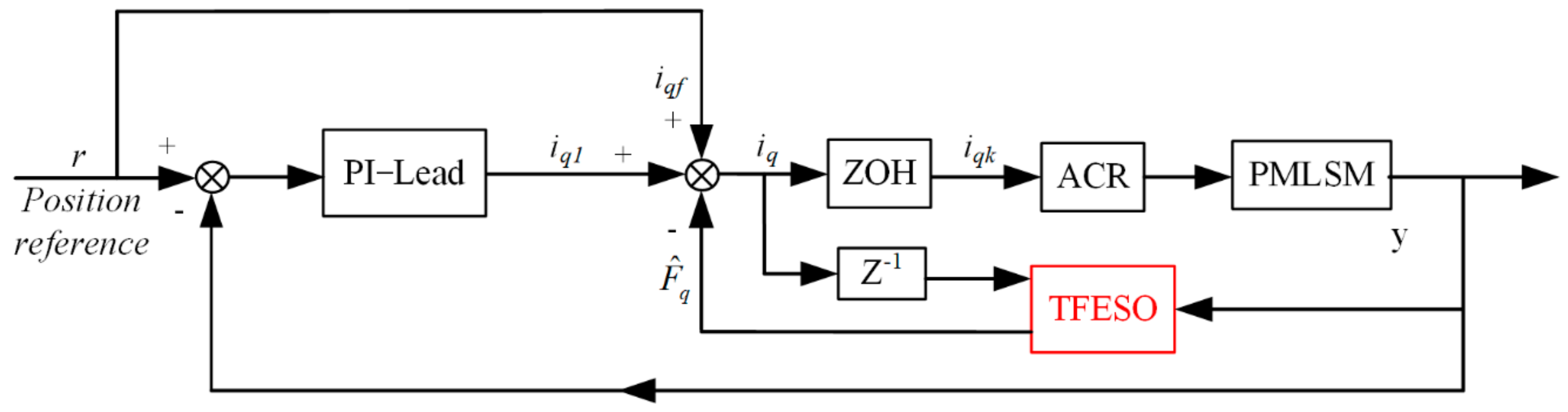
Finally, three degrees of freedom controller based on the PI-Lead controller, the acceleration feedforward and the thrust fluctuation feedforward compensation based on TFESO were shown in Figure 11, where r is the position reference.
5. Experiment Results
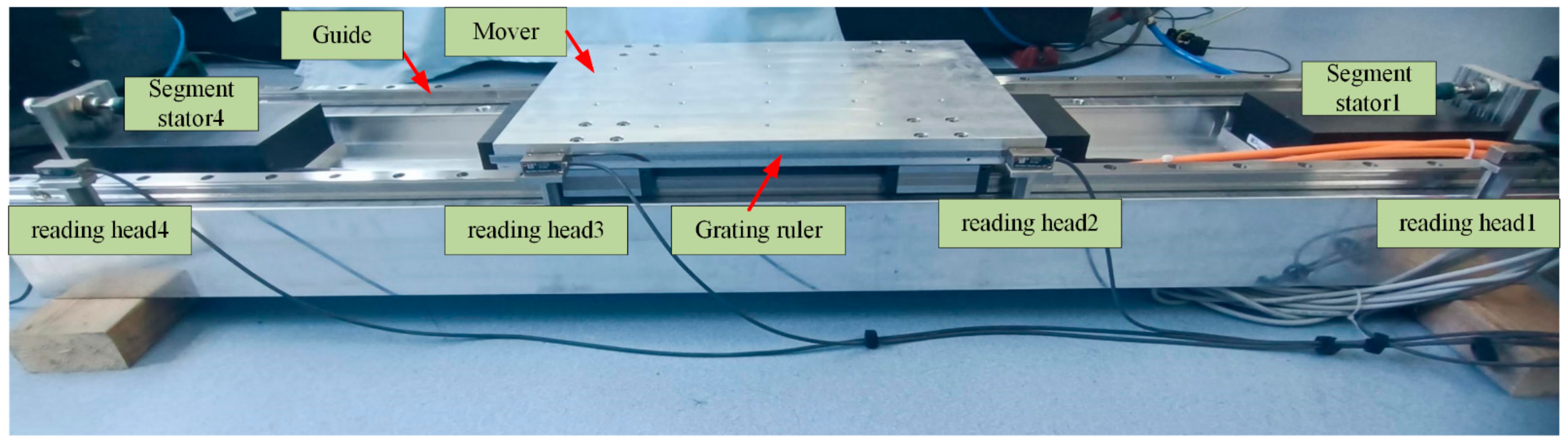
In order to validate the performance of the proposed driver and control strategy, an experimental DSPMLSM was established as shown in Figure 12. The structure of the DSPMLSM is composed of four primary stators and one mover. The mover is supported by guide rails. Four distributed grating ruler reading heads were installed in the whole travel range. The primary stators were made by Akribis (AKM100-B2). The distance between each primary stators is 420 mm, and the pole–slot ratio of the DSPMLSM is 10 poles and 12 slots. The main parameters of the primary stators are shown in Table 1.
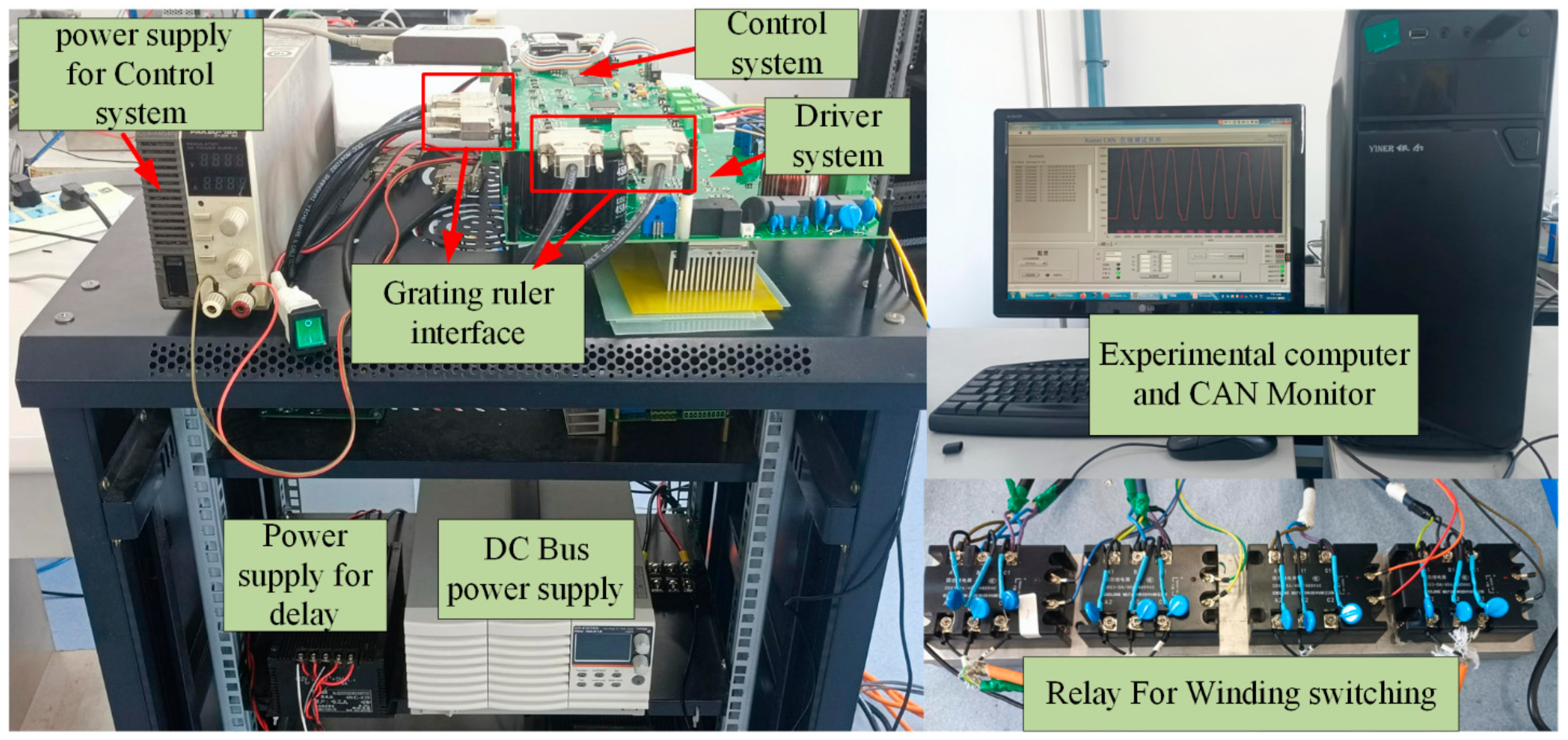
The drive and control system of DSPMLSM was shown in Figure 13. The power supply system contains three power supplies: control system power supply, relay power supply and DC bus power supply. The microprocessor of the control system adopts the digital signal processor (DSP) and field programmable gate array (FPGA). The selected DSP is TMS320F28335, which was a 32-bit floating-point microcontroller with 200 MHz, and the TMS320F28379D is responsible for implementing current sampling, field-oriented control and closed-loop control. The selected FPGA is XCS50, which was used to communicate with four grating ruler reading heads, calculate the current position of the mover, and control the state of the solid-state relays. The communication protocol between TMS320F28379 and FPGA is SPI, and the CAN monitor was used to communicate with TMS320F28379.
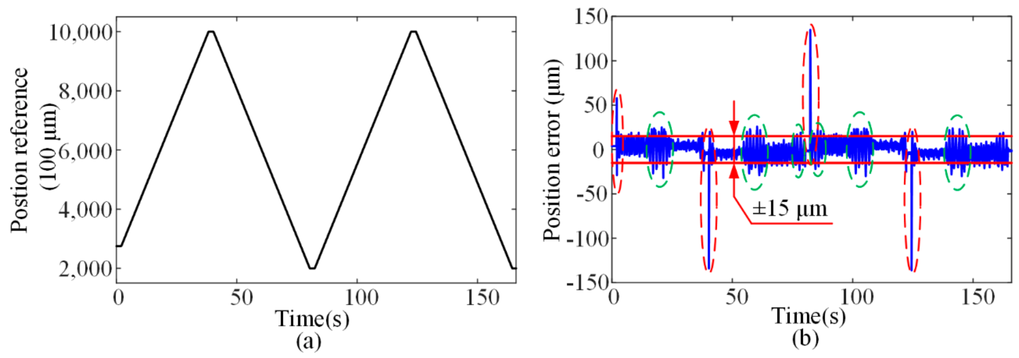
5.1. PI-Lead Position Control
The third-order trajectory planning was adopted to obtain the position reference. At first, the PI-Lead controller which added acceleration feedforward was used to control the DSPMLSM. The trajectory of the position control is a reciprocating motion; The constant velocity is 0.02 m/s, and the acceleration is 0.4 m/s2. The experimental waveform collected by the CAN monitor was shown in Figure 14. From Figure 14b, it can be seen that the position tracking error of the mover is about ±15 μm. As shown by the blue dotted line area in Figure 14b, the large error in the red dotted area was caused by start overshoot. The error in the blue dotted area was caused by inter-segmented thrust fluctuation. We can see that the position error is much larger in the inter-segment region.
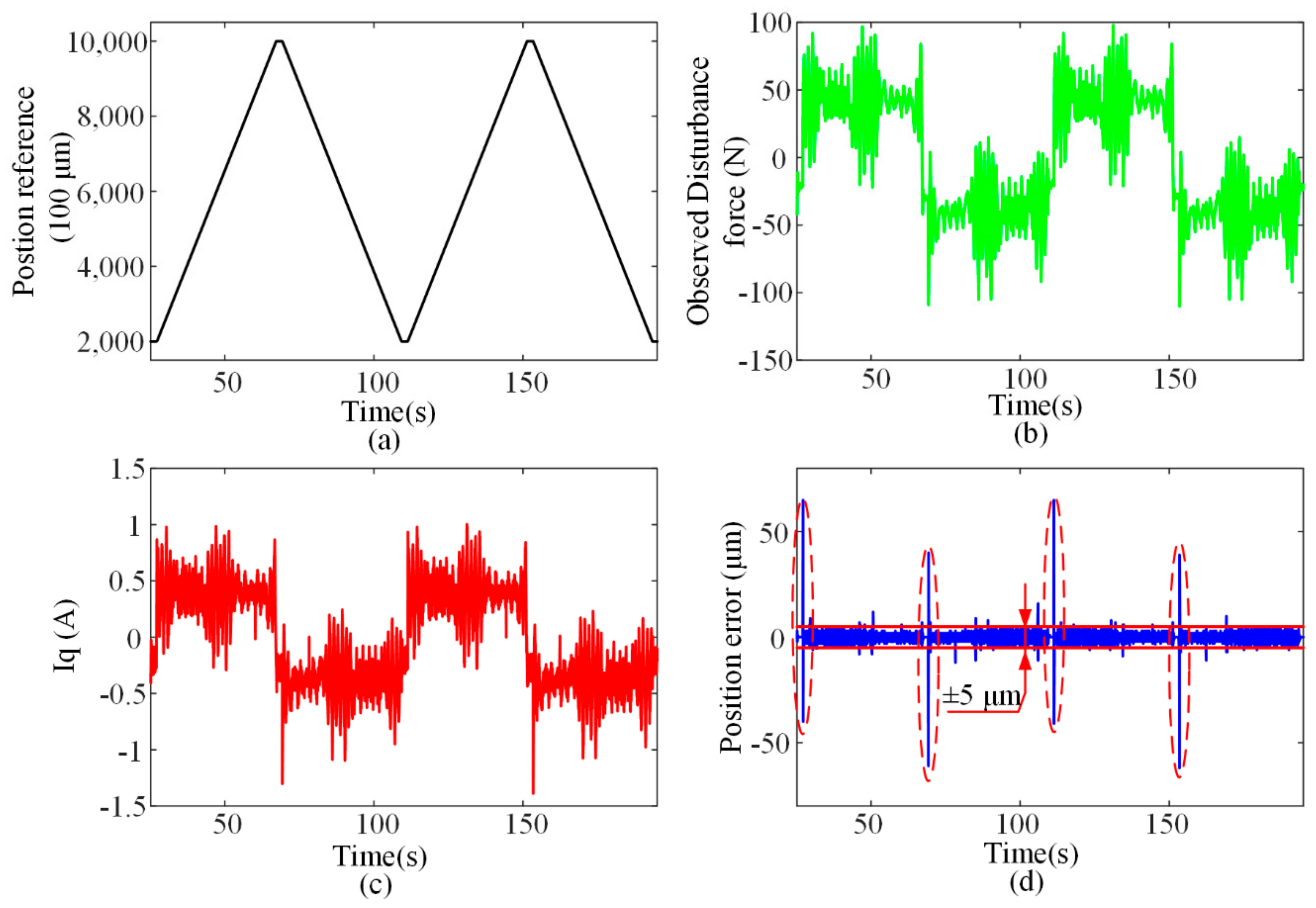
5.2. PI-Lead Position Control and TFESO Feedforward
On the basis of PI-Lead and acceleration feedforward, ESO thrust fluctuation observer feedforward compensation was added, and the observer bandwidth ω = 500 rad/s was set. According to the literature [20], we can calculate the observe gains β1 = 3ω, β2 = 3ω2, β3 = ω3. The experimental waveform is shown in Figure 15.
Figure 15a is the position reference, and Figure 15b is the thrust fluctuation value observed by TFESO. From the observed values, it can be seen that the friction of the guide rail is about 50 N, and there is a large thrust fluctuation of the motor in the inter-segment area, which is consistent with the theoretical analysis. By compensating the observed thrust fluctuation into the thrust reference, it can be seen from Figure 15d that the position tracking error reduced to ±5 μm.
6. Conclusions
The main works of this paper can be summarized as follows.
- Compared with conventional PMLSM, the parameters of DSPMLSM are varied in the inter-segment region, and the thrust coefficient is also varied. In this paper, the inter-segment parameter characteristics of DSPMLSM were systematically analyzed by finite element software.
- According to the characteristics of DSPMLSM systems, the appropriate driver strategy and primary stator switching power supply strategy were proposed, and the experimental stage was built to verify the driver and control strategy.
- The PI-Lead controller and TFESO feedforward were designed to reduce the position tracking error from ±15 μm to ±5 μm, which effectively improves the position tracking accuracy of DSPMLSM.
Author Contributions
Conceptualization, M.W.; methodology, M.W. and K.K.; software, K.K.; validation, K.K., M.W., C.Z.; formal analysis, L.L. and C.Z.; investigation, M.W., L.L.; resources, M.W.; data curation, K.K.; writing—original draft preparation, K.K. and M.W.; writing—review and editing, K.K., M.W. and C.Z.; visualization, K.K.; supervision, M.W. and L.L.; project administration, L.L.; funding acquisition, M.W. All authors have read and agreed to the published version of the manuscript.
Funding
This work was supported in part by the National Natural Science Foundation of China (Grant No. 52077041, Grant No. 51690182) and the Key Laboratory of Special Machine and High Voltage Apparatus (Shenyang University of Technology), ministry of Education (KFKT202108).
Institutional Review Board Statement
Not applicable.
Informed Consent Statement
Not applicable.
Data Availability Statement
Not applicable.
Conflicts of Interest
The authors declare no conflict of interest.
References
- Wang, M.; Yang, R.; Zhang, C.; Cao, J.; Li, L. Inner Loop Design for PMLSM Drives with Thrust Ripple Compensation and High-Performance Current Control. IEEE Trans. Ind. Electron. 2018, 65, 9905–9915. [Google Scholar] [CrossRef]
- Zhang, M.Y.; Wei-ming, M.; Guang-sen, W. Overview on a significant technology of modern aircraft carrier-electromagnetic aircraft launch system. Ship Sci. Technol. 2013, 35, 1–5. (In Chinese) [Google Scholar] [CrossRef]
- Leidhold, R.; Mutschler, P. Speed Sensorless Control of a Long-Stator Linear Synchronous Motor Arranged in Multiple Segments. IEEE Trans. Ind. Electron. 2007, 54, 3246–3254. [Google Scholar] [CrossRef]
- Perreault, B.M. Optimizing Operation of Segmented Stator Linear Synchronous Motors. Proc. IEEE 2009, 97, 1777–1785. [Google Scholar] [CrossRef]
- Kim, Y.; Dohmeki, H. Cogging Force Verification by Deforming the Shape of the Outlet Edge at the Armature of a Stationary Discontinuous Armature PM-LSM. IEEE Trans. Magn. 2007, 43, 2540–2542. [Google Scholar] [CrossRef]
- Kim, Y.; Hwang, S.; Jeong, Y. Cogging Force Reduction of a Stationary Discontinuous Armature PM-LSM by Magnet Segmentation. IEEE Trans. Magn. 2009, 45, 2750–2753. [Google Scholar] [CrossRef]
- Nevaranta, N.; Huikuri, M.; Niemelä, M.; Pyrhönen, J. Cogging Force Compensation of a Discontinuous Permanent Magnet Track Linear Motor Drive. In Proceedings of the 2017 19th European Conference on Power Electronics and Applications (EPE’17 ECCE Europe), Warsaw, Poland, 11–14 September 2017; pp. 1–7. [Google Scholar] [CrossRef]
- Liyi, L.; Mingna, M.; Jiaxi, L.; Chan, C.C. Inductance Analysis in Pass-Through Section for Multi-Segmented Permanent Magnet Linear Motors Based on Magnetic Energy Perturbation. Trans. China Electrotech. Soc. 2013, 28, 46–55. (In Chinese) [Google Scholar] [CrossRef]
- Ma, M.; Li, L.; Zhang, J.; Yu, J.; Zhang, H. Investigation of Cross-Coupling Inductances for Long-Stator PM Linear Motor Arranged in Multiple Segments. IEEE Trans. Magn. 2015, 51, 8205304. [Google Scholar] [CrossRef]
- Guo, K.; Li, Y.; Shi, L.; Zhou, S.; Liu, J.; Fan, M. Non-Linear Mathematic Model of a Segmented Powered Permanent Magnet Linear Synchronous Machine. Trans. China Electrotech. Soc. 2021, 1126–1137. (In Chinese) [Google Scholar] [CrossRef]
- Suzuki, K.; Kim, Y.; Dohmeki, H. Proposal of The Section Change Method of The Stator Block of The Discontinuous Stator Permanent Magnet Type Linear Synchronous Motor Aimed At Long-Distance Transportation. In Proceedings of the 2008 18th International Conference on Electrical Machines, Vilamoura, Portugal, 6–9 September 2008; pp. 1–6. [Google Scholar] [CrossRef]
- Suzuki, K.; Kim, Y.; Dohmeki, H. Driving Method of Permanent-Magnet Linear Synchronous Motor with the Stationary Discontinuous Armature for Long-Distance Transportation System. IEEE Trans. Ind. Electron. 2012, 59, 2227–2235. [Google Scholar] [CrossRef]
- Li, L.; Zhu, H.; Chan, C.C. Optimal inter-segment thrust control applied in primary winding segmented PMLSM. Electr. Mach. Control. 2014, 79–87. [Google Scholar] [CrossRef]
- Rovers, J.M.M.; Jansen, J.W.; Lomonova, E.A. Novel Force Ripple Eduction Method for A Moving-Magnet Linear Synchronous Motor with A Segmented Stator. In Proceedings of the 2008 International Conference on Electrical Machines and Systems, Wuhan, China, 17–20 October 2008; pp. 2942–2947. [Google Scholar]
- Lu, Q.; Yao, Y.; Ye, Y.; Dong, J. Research on Ropeless Elevator Driven by PMLSM. In Proceedings of the 2016 Eleventh International Con-ference on Ecological Vehicles and Renewable Energies (EVER), Monte Carlo, Monaco, 6–8 April 2016; pp. 1–6. [Google Scholar]
- Hong, J.; Pan, D.; Zong, Z. Comparison of the Two Current Predictive-Control Methods for a Segment-Winding Permanent-Magnet Linear Synchronous Motor. IEEE Trans. Plasma Sci. 2013, 41, 1167–1173. [Google Scholar] [CrossRef]
- Wen, T.; Wang, Z.; Xiang, B.; Han, B.; Li, H. Sensorless Control of Segmented PMLSM for Long-Distance Au-to-Transportation System Based on Parameter Calibration. IEEE Access 2020, 8, 102467–102476. [Google Scholar] [CrossRef]
- Cui, L.; Zhang, H.; Jiang, D. Research on High Efficiency V/f Control of Segment Winding Permanent Magnet Linear Synchronous Motor. IEEE Access 2019, 7, 138904–138914. [Google Scholar] [CrossRef]
- Han, J. From PID to Active Disturbance Rejection Control. IEEE Trans. Ind. Electron. 2009, 56, 900–906. [Google Scholar] [CrossRef]
- Gao, Z. Scaling and Bandwidth-Parameterization Based Controller Tuning. In Proceedings of the 2003 American Control Conference, Denver, CO, USA, 4–6 June 2003; pp. 4989–4996. [Google Scholar] [CrossRef]
Figure 1.
Finite element model of DSPMLSM.

Figure 2.
Self-inductance waveform of DSPMLSM.

Figure 3.
Inductance waveform of Phase A. (a) Self−inductance of two adjacent stators in the inter−segment region; (b) mutual inductance of two adjacent stators in the inter−segment region.
Figure 3.
Inductance waveform of Phase A. (a) Self−inductance of two adjacent stators in the inter−segment region; (b) mutual inductance of two adjacent stators in the inter−segment region.

Figure 4.
D−q axis self-inductance and mutual inductance waveform of DSPMLSM. (a) Q axis self−inductance of two adjacent stators in the inter−segment region; (b) d−q axis mutual inductance of two adjacent stators in the inter−segment region; (c) average of q axis self−inductance; (d) average of d−q axis mutual inductance.

Figure 5.
D−q axis flux linkage waveform of DSPMLSM. (a) The d axis flux linkage of two adjacent stators in the inter−segment region; (b) q axis flux linkage of two adjacent stators in the inter−segment region.
Figure 5.
D−q axis flux linkage waveform of DSPMLSM. (a) The d axis flux linkage of two adjacent stators in the inter−segment region; (b) q axis flux linkage of two adjacent stators in the inter−segment region.

Figure 6.
Vector diagram of the DSPMLSM.

Figure 7.
Block diagram of drive and control system for DSPMLSM.

Figure 8.
Strategy of primary stators switching power supply.

Figure 9.
Bode diagram of expected open−loop system.

Figure 10.
Block diagram of the PI−Lead controller and acceleration feedforward control.

Figure 11.
Block diagram of PI−Lead controller, acceleration feedforward and thrust fluctuation observer feedforward.
Figure 11.
Block diagram of PI−Lead controller, acceleration feedforward and thrust fluctuation observer feedforward.

Figure 12.
Structure of DSPMLSM system.

Figure 13.
Driver and control system of DSPMLSM.

Figure 14.
PI−Lead controller experimental results. (a) Position reference; (b) position track error.
Figure 14.
PI−Lead controller experimental results. (a) Position reference; (b) position track error.

Figure 15.
PI-Lead controller and TFESO feedforward. (a) Position reference; (b) observed disturbance force; (c) q axis current of DSPMLSM; (d) position error.
Figure 15.
PI-Lead controller and TFESO feedforward. (a) Position reference; (b) observed disturbance force; (c) q axis current of DSPMLSM; (d) position error.


Table 1.
Main parameters of the primary stators.
| Parameters | Value |
|---|---|
| Phase resistance (Ω) | 4.5 |
| Phase inductance (mH) | 116 |
| Nominal thrust (N) | 1159.3 |
| Peak thrust (N) | 1610.5 |
| Pole distance (mm) | 21 |
Publisher’s Note: MDPI stays neutral with regard to jurisdictional claims in published maps and institutional affiliations. |
© 2021 by the authors. Licensee MDPI, Basel, Switzerland. This article is an open access article distributed under the terms and conditions of the Creative Commons Attribution (CC BY) license (https://creativecommons.org/licenses/by/4.0/).
Share and Cite
MDPI and ACS Style
Wang, M.; Kang, K.; Zhang, C.; Li, L. A Driver and Control Method for Primary Stator Discontinuous Segmented-PMLSM. Symmetry 2021, 13, 2216. https://0-doi-org.brum.beds.ac.uk/10.3390/sym13112216
AMA Style
Wang M, Kang K, Zhang C, Li L. A Driver and Control Method for Primary Stator Discontinuous Segmented-PMLSM. Symmetry. 2021; 13(11):2216. https://0-doi-org.brum.beds.ac.uk/10.3390/sym13112216
Chicago/Turabian StyleWang, Mingyi, Kai Kang, Chengming Zhang, and Liyi Li. 2021. "A Driver and Control Method for Primary Stator Discontinuous Segmented-PMLSM" Symmetry 13, no. 11: 2216. https://0-doi-org.brum.beds.ac.uk/10.3390/sym13112216
Note that from the first issue of 2016, this journal uses article numbers instead of page numbers. See further details here.