
An Equivalent Homogenization Theoretical Method for Composite Sandwich Cylinders Subjected to Pure Bending

School of Mechanical and Power Engineering, Nanjing Tech University, Nanjing 211816, China
*
Authors to whom correspondence should be addressed.
Symmetry 2021, 13(11), 2225; https://0-doi-org.brum.beds.ac.uk/10.3390/sym13112225
Submission received: 6 October 2021
/
Revised: 28 October 2021
/
Accepted: 11 November 2021
/
Published: 21 November 2021
(This article belongs to the Special Issue Symmetry/Asymmetry of Composite Materials and Structures)
Abstract
:An equivalent theoretical homogenization method was proposed for composite sandwich cylinders subjected to pure bending. Firstly, based on a homogeneous orthotropic layer hypothesis, the trapezoidal corrugated sandwich core was found to be equivalent in a homogenization orthotropic layer with the nine equivalent mechanical properties. Then, Lekhnitskii’s theory, based on a unified connection parameter method, was introduced and applied in the equivalent composite sandwich cylinder. The method developed by Lekhnitskii is suitable for arbitrary combinations of winding layers with different winding angles and materials. Additionally, the bending stiffness of the equivalent sandwich cylinder could be calculated. By developing user subroutine of UMAT, the numerical calculation results were in a good agreement with the results of the proposed method. Further, according to the Hill–Tsai strength criterion and the maximum strain criterion, parametric study was done for specified bending stiffness and specified bending strength. The results show that the influence of core parameters on the specified bending stiffness and strength are lower than that of the skin parameters. Additionally, larger skin thickness and smaller winding angles could improve the specified bending stiffness and specified bending strength of the composite corrugated sandwich cylinders.
1. Introduction
Composite sandwich cylinders made of internal and outer skins and a core material with certain topological configurations are widely used in aerospace, aircraft, and building industries due to their high specified stiffness, specified strength, damage tolerance, and blast resistance [1,2,3]. In the past decades, many different lattice core structures have been proposed. It has been proved that corrugated and periodic lattice cores, including Lattice block [4], Tetrahedral truss [5], Pyramidal truss [6], Kagome lattice [7], Woven lattice [8], and Isogrid [9,10], have the potential to enhance numerous applications in aerospace structures. Among these cores, corrugated core is the most widely used because of its simple forming process, low cost, and relatively good mechanical properties. However, most published reports [4,7,11,12,13] deal with axial-compressive behaviors of the composite sandwich cylinders, but rare investigations are involved in their bending behaviors, which is a significant performance index.
A composite thick wall pipe is generally anisotropic. After deformation caused by various types of loading, such as internal or external pressure, axial pressure, or torsion, the axis of the composite thick wall pipe is still straight. However, under bending condition, deflection occurs on the axis of the thick wall pipe, which makes the deformation prediction more complex. Earlier, Lekhnitskii [14] used the flexibility method of a double stress function to obtain two partial differential equations for the case of cylindrical anisotropy. Later, Jolicoeur and Cardou [15] developed and expanded Lekhnitskii’s theory. The developed theory is only suitable for spiral wound layers and not for special winding layers with orientation n of 0° and 90°. Xia et al. [16] treated cross-winding layers to 90° winding layers. A single stress function was used to establish differential equations because out-of-plane shear stresses are zero, which limits the scope of application of their method. In 2014, Zhang and Hoa [17,18] proposed a unified connection parameter method. This method overcomes the problem of singular parameters in the presence of a special winding layer and is suitable for composite tubes of general stacking sequence including 0°, 90°, and [/−].
The periodic topological core structure in composite sandwich cylinders is another complex factor. In the past few decades, the research on cores’ equivalent theory has mainly focused on the in-plane stiffness of sandwich panels. For corrugated cores, Libove and Hubka et al. [19] proposed that shear effects were an important phenomenon that could not be neglected. Based on the Classical Plate Theory (CPT), Xia et al. [20] derived the in-plane equivalent mechanical properties for different corrugation cores. Bartolozzi et al. [21] derived the in-plane equivalent mechanical properties of a sinusoidal-shaped corrugated core using an energy method. Then, Bartolozzi et al. further extended the energy method to make it suitable for arbitrary shapes of corrugated cores [22]. Based on the classical Euler–Bernoulli and line hypotheses, Magnucka-Blandzi et al. [23,24] analyzed the bending and buckling behavior and the effect of transverse shearing deformation on sandwich beams with sinusoidal corrugated cores. They also studied the effect of transverse shearing deformation for short and long beams. For corrugated cores, equivalent out-of-plane properties are also important and cannot be ignored [25]. Therefore, Zhang and Lei et al. [26] studied the out-of-plane compressive performance and energy absorption of multi-layer graded sinusoidal corrugated sandwich panels. Ghahfarokhi et al. [27] use a new approach to reveal the damage mode of global buckling and the equivalent stiffness of composite sandwich cylindrical shells with lattice cores under uniaxial compression. In the context of shear deformation theory, Yadav et al. [28] studied circular cylindrical sandwich shells with open/closed cellular core the face sheets. Additionally, their effective mechanical properties were determined using the Gibson and Ashby model and the rule of mixture. Guo et al. [29] proposed a unified semi-analytical method for dynamic homogenization and vibration of lattice-truss-core sandwich beams. Based on the mechanics of materials approach and the classical plate theory, Pydah et al. [30] analytically investigate infinitesimal cylindrical bending deformations of two-layered triangular corrugated and webcore linearly elastic sandwich panels. Kolpakov et al. [31] derived the equivalent stiffnesses for corrugated plates by using a two-step approximation method. For corrugated core sandwich panels, Buannic et al. [32] applied a specific study to derive the transverse shear stiffness and determined an equivalent Reissner–Mindlin homogeneous plate.
This paper proposes an equivalent homogenization theoretical method for composite sandwich cylinder under pure bending. Firstly, based on a homogeneous orthotropic layer hypothesis, the trapezoidal-shaped corrugated sandwich core was approximately equivalent to an orthotropic homogenization layer. This layer was described with nine equivalent mechanical properties. Then, Lekhnitskii’s theory, based on a unified connection parameter method, was introduced and applied in the equivalent composite sandwich cylinder. By developing a user subroutine of UMAT, the results of the equivalent homogenization theoretical method were compared with the numerical results. Further, according to the characteristics of the sandwich cylinder, two different strength criteria for skin and core are discussed. The influence of variable parameters on specified bending stiffness and strength is discussed with a parametric study.
2. Materials and Methods
2.1. Analytical Methods for Composite Cylinders Subjected to Pure Bending
After years of development, the range of application of the elasticity theory for composite cylinders subjected to pure bending has been continuously expanded. This elasticity theory is an important basis for the sandwich cylinder subjected to pure bending. Additionally, the theory was introduced in this section.
2.1.1. Analytical 3D Elasticity Method by Lekhnitskii
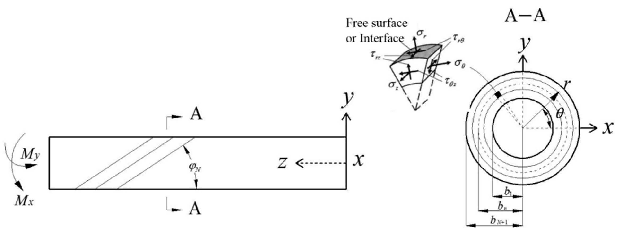
A composite tube with multiple layers under a pure bending load and is shown in Figure 1 [18], where , and are the inner and outer radius of the nth layer and its filament winding angle, respectively. Additionally, , is the main bending stress component along the axis in the composite pipe. The in-plane stress components of , , and are parallel to the cross-section are the secondary stress components, and the stress components of and are the out-of-plane stress perpendicular to the cross-section.
Relationship between strain and stress of single-layer composite winding layer in material principal axis coordinate system can be expressed as
where
Based on the winding angle of , the constitutive equation of each layer transformed from the principal material coordinate system to the cylindrical system can be obtained as follows [18]:
where
in which
To simplify the expression, the following reduced elastic constants were defined by Lekhnitskii [14]
For the pure bending problem of composite pipes, Lekhnitskii [14] first proposed the flexibility method containing two stress functions, and . The in-plane stress component is expressed as the following form of stress function .
Meanwhile, the out-of-plane stress component is expressed as follows.
Additionally, the three-dimensional elastic mechanical problem of pure bending of a composite pipe is a generalized plane strain problem, and its bending stress can be expressed as follows:
A system of ordinary differential equations can be obtained with separate variables, and the solution is sought as follows.
where and are the curvature in the plane perpendicular to directions x and y, respectively.
According to the compatibility equations [14], the following ordinary differential equation about the stress function can be obtained.
2.1.2. Solutions for Composite Tube with Multi-Layer
Based on Lekhnitskii [14], Jolicoeu and Cardou [15] considered the fourth-order ordinary-differential-compatibility equation of pure bending problem of composite tube with multi-layer and arbitrary winding angle. System (12) is of the Cauchy–Euler type. The form of the solution of and were assumed. The complete solutions of the pure bending system for the stress function are
where are four characteristic roots given by
with
and are the two unknown constants. The solution is written in matrix form as
are four connection parameters obtained from
Additionally, are four combination coefficients that are calculated with the continuity boundary condition.
2.1.3. The Unified Connection Parameter Method
According to the above method proposed by Jolicoeur and Cardou [15], Zhang et al. [18] found the connection parameters of and are infinite in and . In order to overcome this issue, the unified connection parameter method was proposed by
Then, the four combination coefficients of are transformed into . Additionally, the six stresses are as follows.
The displacements are expressed as follows
where functions , , and are finally written as
where and .
In the context of no relative slip between layers in the composite tubecase, the stresses , , and and displacements , , and must meet the continuity condition. For a composite tube with N layers, there are two free surfaces yielding two equations each, plus (N − 1) interfaces giving five equations each. The value is set to zero [15]. This gives 5N equations for the same number of arbitrary constants (, and for each cylinder). Then, the 5N arbitrary constants can be calculated. The end conditions of pure bending are given by
2.2. Equivalent Properties of Trapezoidal Corrugated Cores
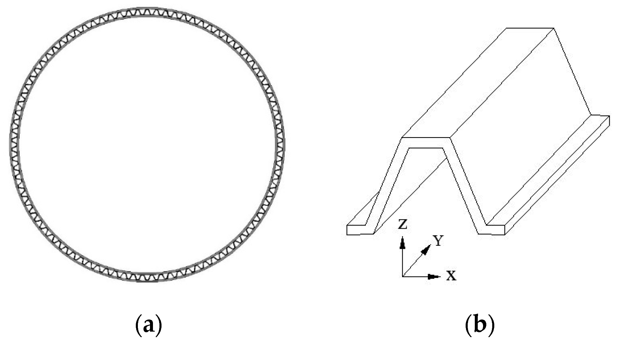
In recent years [12,33,34], the sandwich structures with trapezoidal corrugated-cores, as shown in Figure 2, have been of great concern due to their simple forming process, low cost, and sufficient bonding area. Therefore, the precise equivalent parameters of corrugated core have an important influence on the strength and stiffness design of sandwich structure.
Unlike triangular-shaped cores and sinusoidal cores, the trapezoidal cores are composed of two parts: the horizontal segment and the corrugated segment. Based on Mindlin–Reissner theory, H. Mohammadi [35] and M. Shaban [25] established a quarter trapezoidal cell model and the boundary conditions (BCs) of a dummy moment . A vertical force and a horizontal force were applied at the end of the horizontal part. Although their calculated results of equivalent mechanical properties are consistent with the simulation under the same BCs, their methods are only suitable for the trapezoidal corrugated cores without skins. The actual BCs are different between trapezoidal-shaped corrugated sandwich plates with two skins and without skins. In order to accurately calculate the equivalent parameters, the correct boundary condition should be to apply forces and constraints at the conjunction points of the core with skins [22].
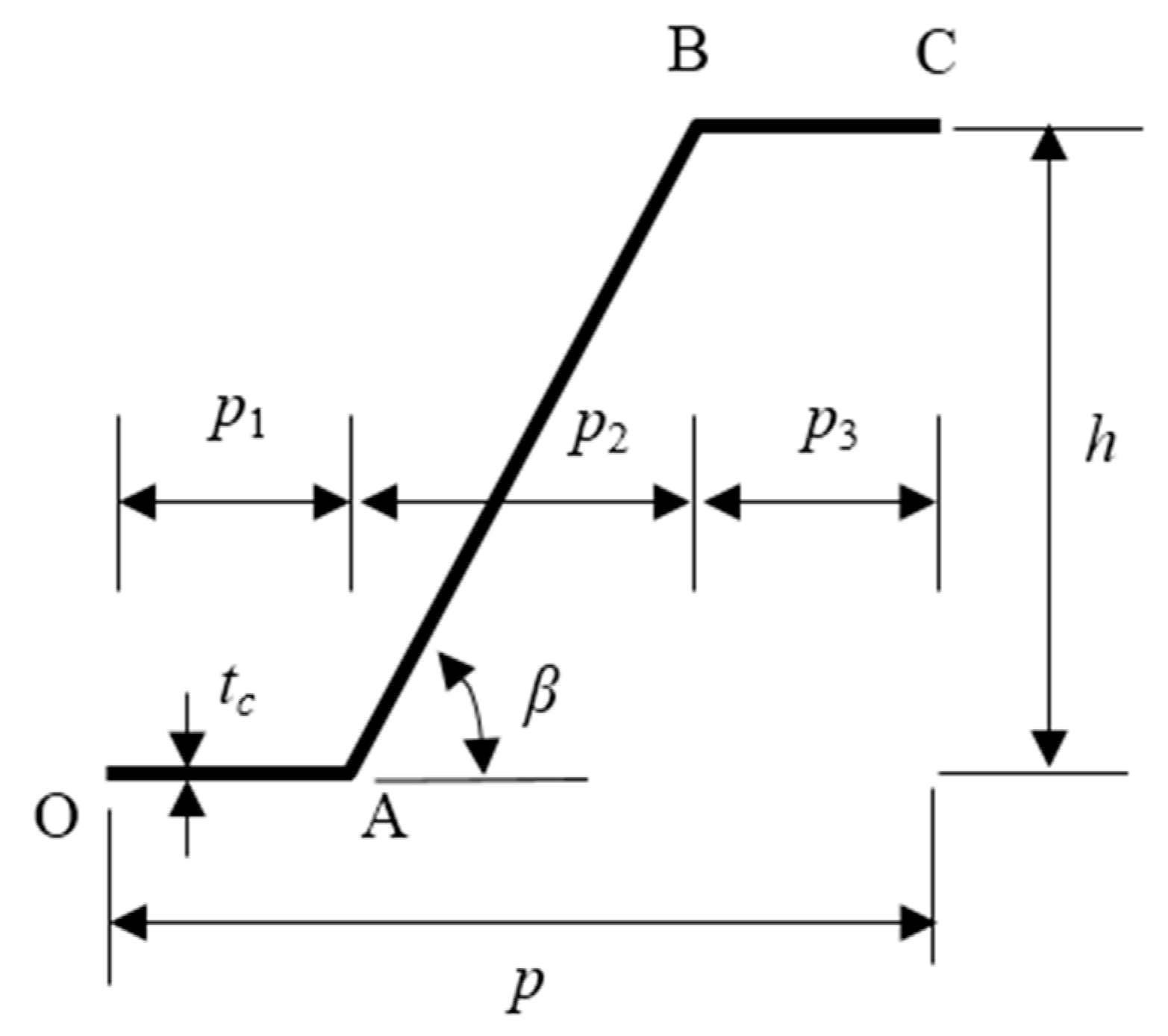
As shown in Figure 3, a half-trapezoidal cell model represented by its centerline was proposed by Giorgio Bartolozzi [21,22], where p1, p2, and p3 are the lengths of three parts (Part O–A, Part A–B, and Part B–C, respectively) along the x-direction. The corrugation cores can be considered periodic with period 2 × p, dip angle β, and height h.
Generally, the corrugated cores are made of lightweight metal by a stamping and folding process [36] or carbon fiber woven composite by a mold-pressing method [12]. Additionally, the carbon fiber woven composite with symmetric orthogonal ply has an in-plane quasi-isotropic characteristic, which could be treated as a metal material.
2.2.1. Transverse Shear Modulus Gxz
The corrugation part (Part A–B in Figure 3) of a trapezoidal core is the main deformation element that determines the mechanical characteristics of the whole core. Indeed, it is necessary to calculate the deformation of Part A–B.
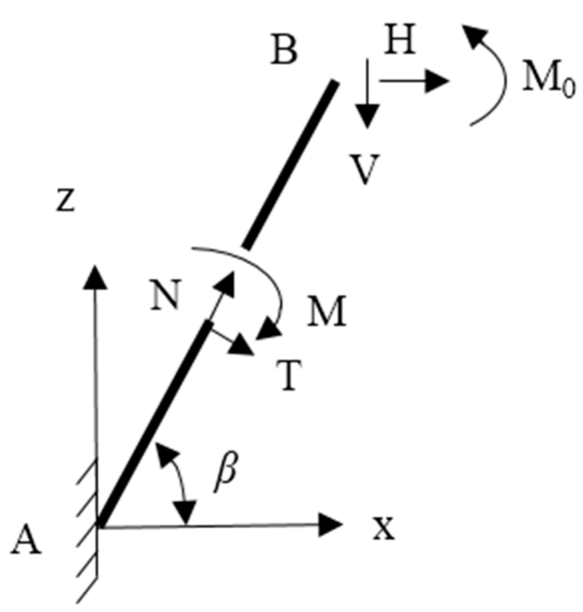
As shown in Figure 4, the analytical model of Part A–B has thickness tc and unit width b = 1 in the y-direction. The origin of the XYZ coordinate system is set at point A, which is the conjunction points of the core with skins, and there the structure is clamped. In order to determine the equivalent shear modulus Gxz, a horizontal force , a dummy moment , and a vertical force are applied at point B. Then, the Part A-B will only produce the horizontal displacement , which is also called pure shear deformation (see Figure 5).
The inner forces of arbitrary point in Part A–B are as follows.
Based on the Castilian second theorem [11], the rotation displacement, vertical displacement, and horizontal displacement of the free end of point B can be derived as:
According to the boundary conditions shown in Equation (32), the horizontal displacement can be calculated from the equations shown in Equation (33).
where
and , , and is the shear correction factor of the beam (). The horizontal displacement can be found with
Therefore, the equivalent transverse shear modulus of Part A–B can be obtained as follows:
In the case of containing upper and lower skins, since the horizontal sections (O–A and B–C) of the trapezoidal corrugated core are constrained by the skin and have little effect on the transverse shear deformation of the core under the action of the horizontal force in the x direction, the equivalent transverse shear modulus of the whole corrugated core can be derived with
2.2.2. Elastic Modulus in the X-Direction and Poisson’s Ratio
To determine the equivalent elastic modulus in the x-direction , it is necessary to determine the horizontal displacement of the upper end due to a horizontal force . The calculation approach is like , but there is no dummy vertical force . Therefore, according to Equation (33) and considering the conditions of , and at point B are finally imposed. The arising system of three equations with three unknowns can be solved to determine .
Additionally, the equivalent Young’s modulus of Part A–B is derived as follows:
Hence, the equivalent elastic modulus in the x-direction of the whole trapezoidal-shaped corrugation is
where and represent the equivalent elastic modulus of Part O–A and Part B–C, respectively, and
Furthermore, Poisson’s ratio can be derived as
2.2.3. Elastic Modulus in the Y-Direction
The equivalent elastic modulus in the y direction can be calculated by Equation (44), which scales the Young’s modulus of the core to the ratio between the sectional area of corrugated core in X–Z plane, , and the section area of the equivalent volume, .
2.2.4. Transverse Shear Modulus in Y–Z Plane
The transverse shear modulus can be obtained by simplifying the shape of trapezoidal corrugated core. In the sample domain of half a period, the core is stretched to a flattened panel. This corresponds to creating a local curved system of reference along the center line of the core sheet and integrating along that local coordinate. Then, the panel can be considered as a straight beam with a rectangular section. Based on Timoshenko beam theory, the displacement in the y direction due to an applied force in the same direction is derived as
where and b is the width of the core in the y direction. The shear deformation of the equivalent sample section, , under the same conditions, is
By imposing that and are equal, the equivalent shear modulus of Part A–B is obtained as
Then, the transverse shear modulus in the Y–Z plane of the trapezoidal corrugation is approximated as:
2.2.5. In-Plane Shear Modulus
The derivation method of in-plane shear modulus is similar to the derivation method of transverse shear modulus in the Y–Z plane .The only difference is that now the force is acting in the x direction. Therefore, the shear deformations computed for the approximated section and for the equivalent sample section are:
By imposing that and are equal, the equivalent shear modulus is obtained as
2.2.6. In-Plane Poisson’s Ratio
Poisson’s ratio of typical orthotropic materials can be obtained from the following relation:
The Poisson’s ratio in the X–Y plane can be assumed to be equal to the constituent material Poisson’s ratio [22].
2.2.7. Out-of-Plane Elastic Modulus in Z-Direction
As represented in Figure 2, the derivation of elastic modulus in the z direction is similar to that of the elastic modulus in the x direction. By imposing a vertical force in the z direction to the point B, positive vertical displacement, , and negative horizontal displacement in the x-direction, , occur. Additionally, in order to avoid rotation in the X–Z plane, a dummy moment will be produced at point B. Therefore, according to Equation (33) and considering the conditions of , , and , the arising system of three equations with three unknowns can be solved to determine and :
Additionally, the equivalent Young’s modulus is obtained as:
2.2.8. Poisson’s Ratio
The Poisson’s ratio, , is obtained from the following relation:
Similar to the calculation of , the Poisson’s ratio of can also be assumed to be equal to the constituent material of Poisson’s ratio. Additionally, then, can be calculated by Equation (57).
2.2.9. Relative Density
The relative density of the equivalent material is computed by scaling the density of the constituent material proportionally to the occupied equivalent volume, thus
Generally, the present theoretical results are almost consistent with the calculated results of the FEA shell elements models with the same boundary conditions [21,22,23,24,25]. By comparing the results of the FEA model and Xia’s method [20], Bartolozzi et al. [22] proved that the proposed method can still be used with good accuracy for trapezoidal corrugated cores with relatively short horizontal segments. Furthermore, compared with Xia’s method, the proposed method can further calculate the out-of-plane equivalent properties.
2.3. The Theoretical Equivalent Homogenization Method for a Sandwich Cylinder
Composite sandwich tubes are widely used in many fields such as civil, aerospace, and military. In the civil field, high-pressure long-tube trailers are an important way to transport hydrogen, compressed natural gas, and other fuels in a short distance. Compared with the traditional steel container, the composite cylinder has higher efficiency of storage and transportation, but, as a result of increases in composite cylinder volume, a longer bottle body would lower the stiffness of the vessel. Therefore, large-volume full-winding hydrogen bottles should not only meet the requirements of their internal pressure strength but should also still meet the tube body stiffness requirements in service conditions. In the field of aeronautics and astronautics, a lightweight composite allio sandwich tube structure can meet the requirements of the bearing performance of large engine shells under complex working conditions, and the dialectical unity of its bending stiffness, axial compression performance, and lightweight is continuously pursued in the design process. In the military field, the improvement of the bending stiffness of the lightweight composite rocket launcher can effectively reduce the lateral vibration during launch, reduce the velocity deviation of the projectile leaving the launcher, and improve the hit accuracy. Therefore, the bending stiffness of composite sandwich tubes is a significant performance index. It is urgent to establish an effective analysis method to design the bending stiffness of this kind of structure.
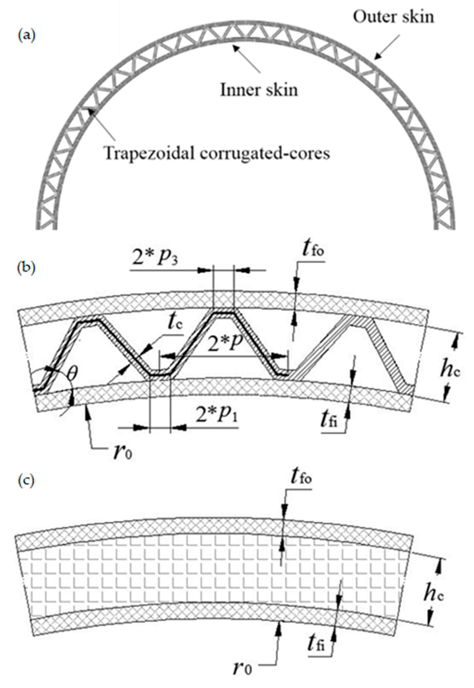
An equivalent homogenization theoretical method is proposed to analyze the pure bending of a sandwich cylinder. As shown in Figure 6a, the sandwich cylinder is composed of the inner skin, lightweight core, and outer skin. The geometric parameters of the trapezoidal corrugated core are shown in Figure 6b. According to the equivalent theory model of trapezoidal corrugated core in Section 3, the core could be approximated to an orthotropic layer with equivalent mechanical properties. As shown in Figure 6c, the core could be simplified into an orthotropic homogeneous layer with the same height as hc. By using the developed Lekhnitskii’s theory, the equivalent bending stiffness of the corrugated-core sandwich cylinder can be calculated.
3. Results
To compare with the proposed equivalent homogenization theoretical method, a 3D finite element model of the sandwich cylinder was established and calculated by ABAQUS 6.13. As shown in Figure 6b, the geometric parameters of inner skin, outer skin, and the trapezoidal corrugated core are listed in Table 1. The inner and outer skin have two layers with the same thickness of 0.8 mm. The material of the core is standard aluminum with = 71,000 MPa and = 0.33. The material of the inner and outer skin is carbon fiber/epoxy resin with anisotropic elastic properties listed in Table 2.
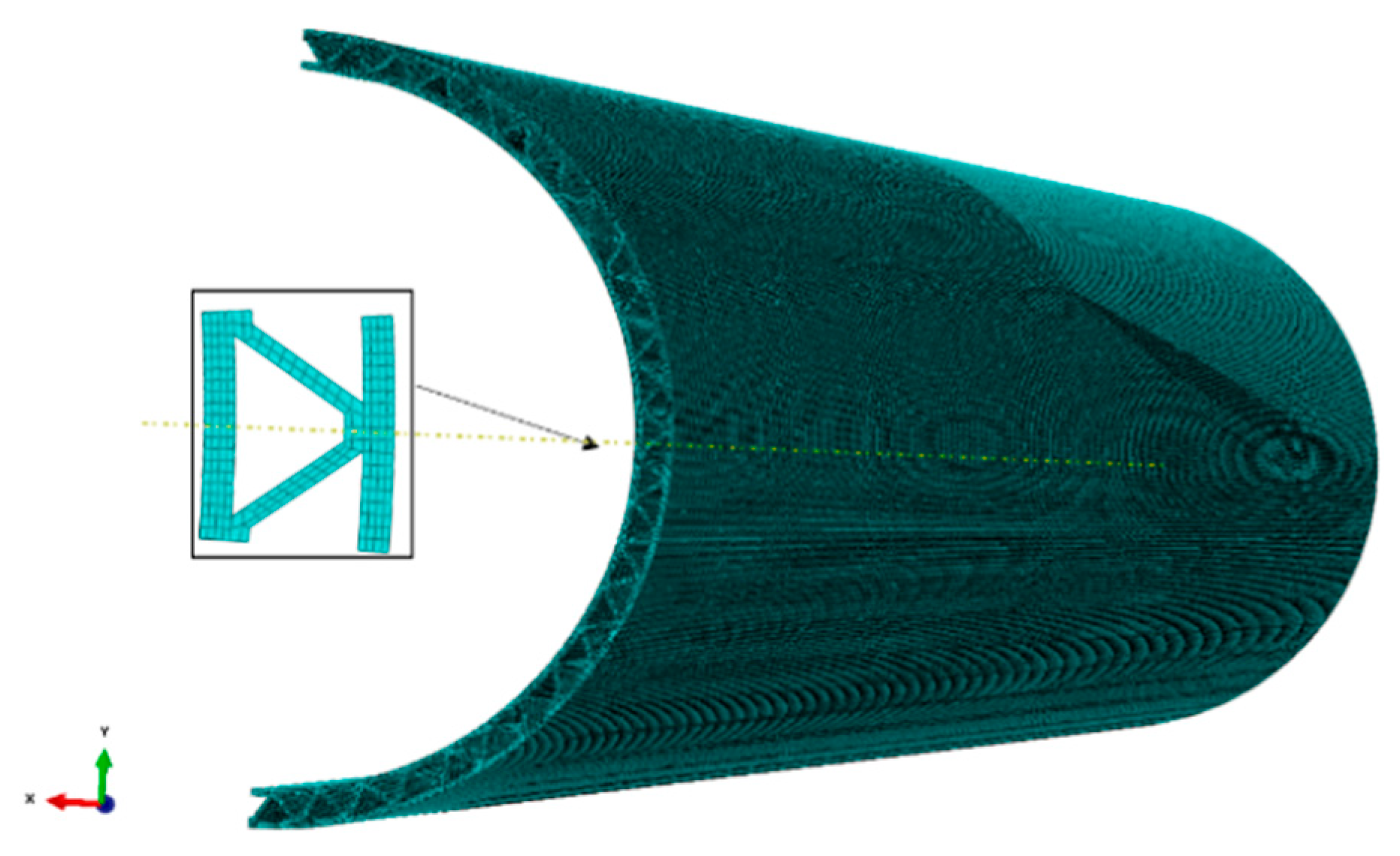
By developing the user subroutine of UMAT, the orthotropic linear elastic constitutive model is applied in the ABAQUS Implicit Solver. Considering that many meshes require a considerable amount of computing resources, the semi-model of the sandwich cylinder was established. As shown in Figure 7, there are 1000 regular elements in the circumferential direction, 2 regular elements of each layer in the thickness direction, and 200 regular elements in the axial direction. The linearly distributed load with the equivalent moment of = 6 × 10⁶ N·mm and = 0 N·mm was applied on the semi-model. Additionally, the Y–Z section of the model is symmetrically constrained.
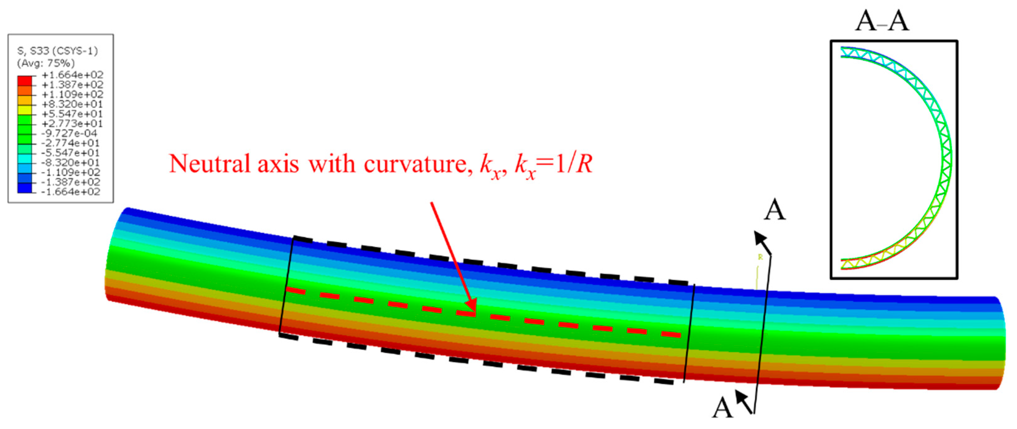
As shown in Figure 8, under the equivalent moment, = 6 × 10⁶ N·mm, the axial stress component at the position of θ = 90° is greater than that at other positions. In order to measure the bending curvature of the cylinder, we chose a length of the cylinder to extract the deformed coordinates of the nodes at the position of θ = 90° and 270°. Additionally, the coordinates of the deformed central axis can be calculated, as shown in Figure 8. Because the deformation of the cylinder is symmetrical to the x-axis, only the coordinates of the central axis in the Y–Z plane need to be considered. It is known that every three adjacent nodes in Y–Z plane can determine a circle with a radius, R. The cylinder’s bending radius can be determined by averaging the corresponding radius of all nodes in the central axis.
According to the proposed equivalent homogenization theoretical method, the trapezoidal corrugated core with geometric parameters listed in Table 1 needs to be equivalent to an orthotropic homogenization layer. The mechanical properties are shown in Table 3.
Then, the curvature of the equivalent cylinder can be calculated by Equation (28). The numerical and theoretical results are shown in Table 4, which shows that the results of the equivalent method were in good agreement with numerical results.
4. Discussion
4.1. The Bending Strength of Sandwich Cylinder
The advantage of the theoretical method is that the core layer is simplified as a homogenized layer, making the sandwich cylinder’s three-dimensional elastic analysis possible.
Intuitively, the bending stiffness of the cylinder can be improved by reducing the winding angle of the inner skin and outer skin. The calculation of the bending strength can reflect the utilization rate of the materials in each layer of the sandwich cylinder. Therefore, the bending strength of sandwich cylinder is also important.
4.1.1. Strength Criterion for the Cylinder’s Skin
The inner and outer skins of the cylinder are composed of winding layers with different materials, angles, and thicknesses. The failure of skins belongs to the progressive failure of each layer. Therefore, it is of great significance to find out the earliest failure location and the failure load. In recent years, many strength criteria [37] have been developed for fiber-reinforced resin matrix composites. In this paper, the Hill–Tsai strength criterion is used to evaluate the strength failure of the winding layers of skin. Additionally, the failure determination formula is
where is the failure factor; , , , , , and are the stress components in the material principal coordinate system of 1-2-3 directions; and , , and are the shear strength in the corresponding principal axis directions.
If , then ; otherwise .
If , then , and ; otherwise , , .
If , then , and ; otherwise , and .
If or , then , and ; otherwise , and .
where , , and represent compressive strength and , and represent tensile strength in the principal directions. When the stress components of a material point make , the material point is considered to be damaged. According to the explicit stress expression of the developed Lekhnitskii’s theory mentioned in Section 2.3, it is possible to predict the failure location. As shown in Equation (44), the stress components need to be transformed into corresponding stress components in material principal coordinate system.
4.1.2. Strength Criterion for the Core
For a sandwich cylinder, the neutral layer is coplanar with the axis, which will cause a complex stress distribution along with the circumferential and radial directions. Therefore, the actual stress state of the core with multi-corrugation shapes is more complicated. Although the stress of each layer is not necessarily continuous, the strain along the circumferential and radial direction must be continuous. For a trapezoidal corrugated core, the axial stiffness is much greater than that in other directions. Additionally, the main strain is in the axial direction of the cylinder, which causes that the to be much greater than other stress components at each layer, as shown in Figure 2. When the core’s axial displacement reaches the maximum uniaxial strain of the core material, failure is considered to have occurred in the core. Therefore, the maximum strain criterion was applied in this paper to evaluate the failure of cores, which is expressed as
where is the maximum strain component in the z-direction of the core layer, is the critical failure strain of the core material, and is the strength of the core material. Generally, the corrugated cores are made of lightweight metal or woven carbon fiber composite with symmetric orthogonal ply. For metal material, is the yield strength and is the elastic modulus.
When the core is made of woven carbon fiber composite with ply order of [0/90]ns, , , and are the equivalent tensile strength, compressive strength, and elastic modulus of the [0/90]ns laminated plate, respectively. According to classical laminated plate theory, the relationship between the internal force and the deformation in the middle plane of a laminate is established as
where matrix elements , , and are the tensile, coupling, and bending flexibility, respectively. For the laminated plate with symmetric ply, the coupling flexibility matrix is a null matrix. The relationship above can be simplified into
where h is the thickness of the laminated. The effective in-plane engineering constant can be presented as
When the layup configuration of the core is orthogonal and symmetrical, the laminate has an in-plane quasi-isotropic characteristic. Therefore, the equivalent theory model of trapezoidal corrugated cores is also applicable to the above composite cores. The in-plane elastic modulus of the core can be determined as .
4.2. Parametric Study for Specified Bending Stiffness and Specified Bending Strength
There are many parameters that affect the mechanical properties of sandwich cylinders. Based on the geometric parameters listed in Table 4, the specified bending stiffness (the ratio of bending stiffness to structure density) and specified bending strength (the ratio of bending strength to structure density) were studied under variable parameters of skin thickness, winding angles of skin, corrugated rib thickness, and core materials. The material properties of winding layers and cores are listed in Table 5. When the material of the core is woven carbon fiber composite, the effective in-plane engineering constant can be calculated according to classical laminated plate theory. However, it is more convenient to test the material property of a [0/90]ns laminated plate [11] directly. The thickness of each winding layer is 0.2 mm. In the process of the parametric study, the intermediate diameter of the core was kept unchanged.
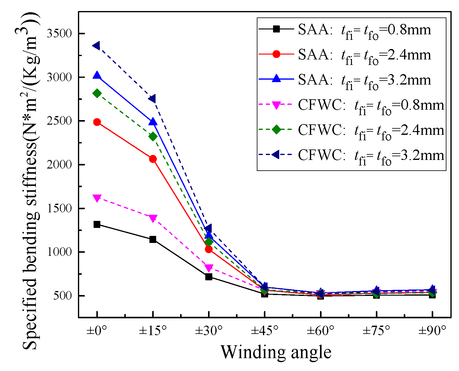
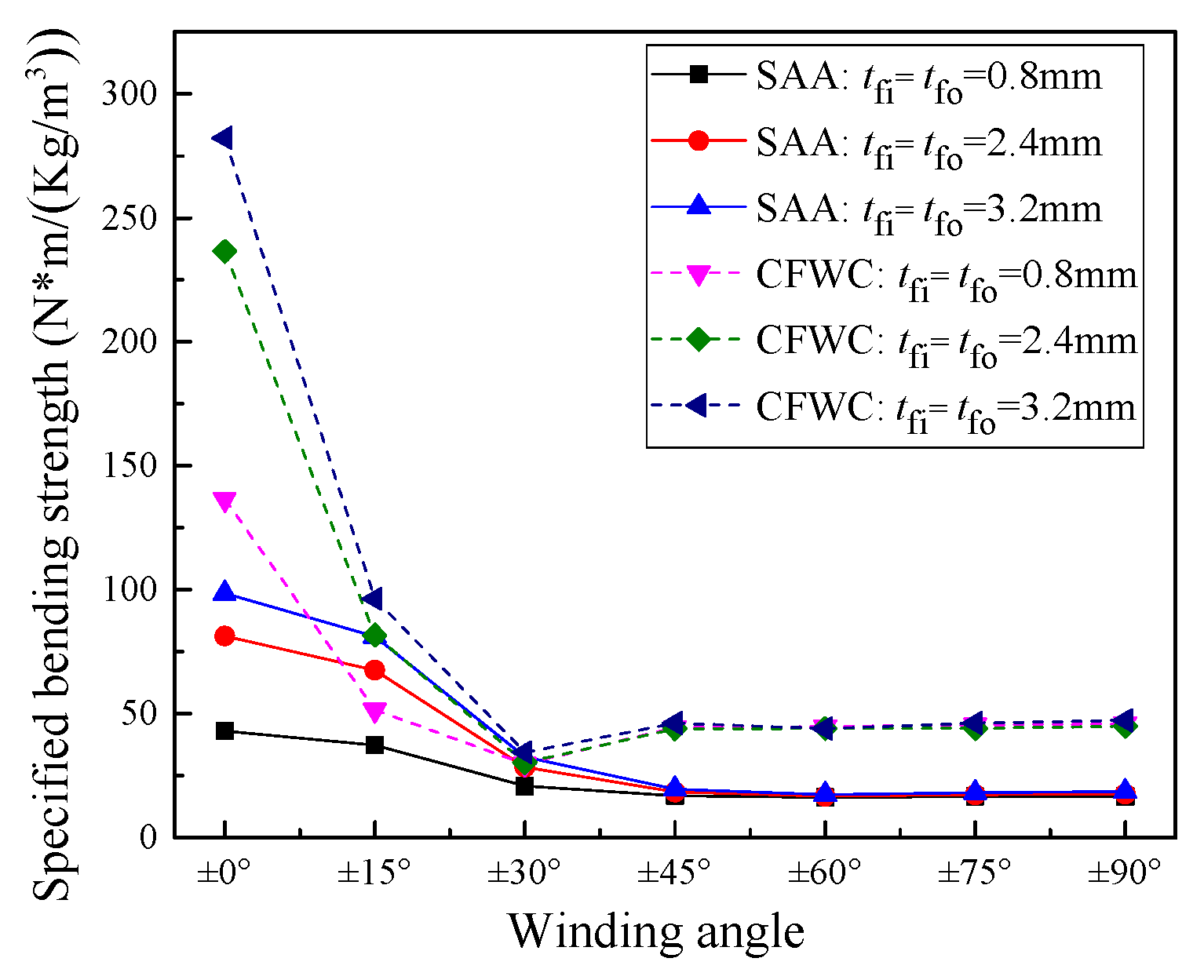
According to the density of each layer listed in Table 5 and the core density, , calculated by Equation (58), the equivalent density of the sandwich cylinder can be obtained. As shown in Figure 9, the influence of core material on standard aluminum alloy (SAA) and carbon fiber woven composite (CFWC) with [0/90]ns was studied and contrasted. The winding angles and thickness of inner and outer skin remain the same. With the increase in winding angle, the specified bending stiffness of the sandwich cylinder drops rapidly at winding angle interval of 0° to ±45°. It keeps at an almost constant level at the interval of ±45° to ±90°. This is because the trapezoidal corrugated core is the main contributor to the specified bending stiffness at winding angle interval of ±45° to ±90°. The cores made of woven carbon fiber composite with lower in-plane elastic modulus show a higher specified bending stiffness due to its lightweight materials characteristic. Further, the specified bending strength with the same parameters is shown in Figure 10. For aluminum alloy cores, the unique failure mode is its yield failure. When the core becomes the main contributor to the specified bending stiffness at winding angle intervals of ±45° to ±90°, the specified bending strength no longer changes significantly. The sandwich cylinder with the composite core has different failure modes. When the skin winding angels are ±15°, ±30°, and ±45°, the failure mode is skin failure, which is mainly caused by the resin matrix tension at the positions of and . Therefore, due to the transition of the failure modes, the bending strength reaches its minimum at the winding angle of ±30°. The other failure mode is core failure at winding angels of 0°, ±60°, ±75°, and 90°. The phenomenon above proves that the multi-winding angles are necessary to improve the skin stiffness of other directions and prevent the matrix failure from tensile load in advance.
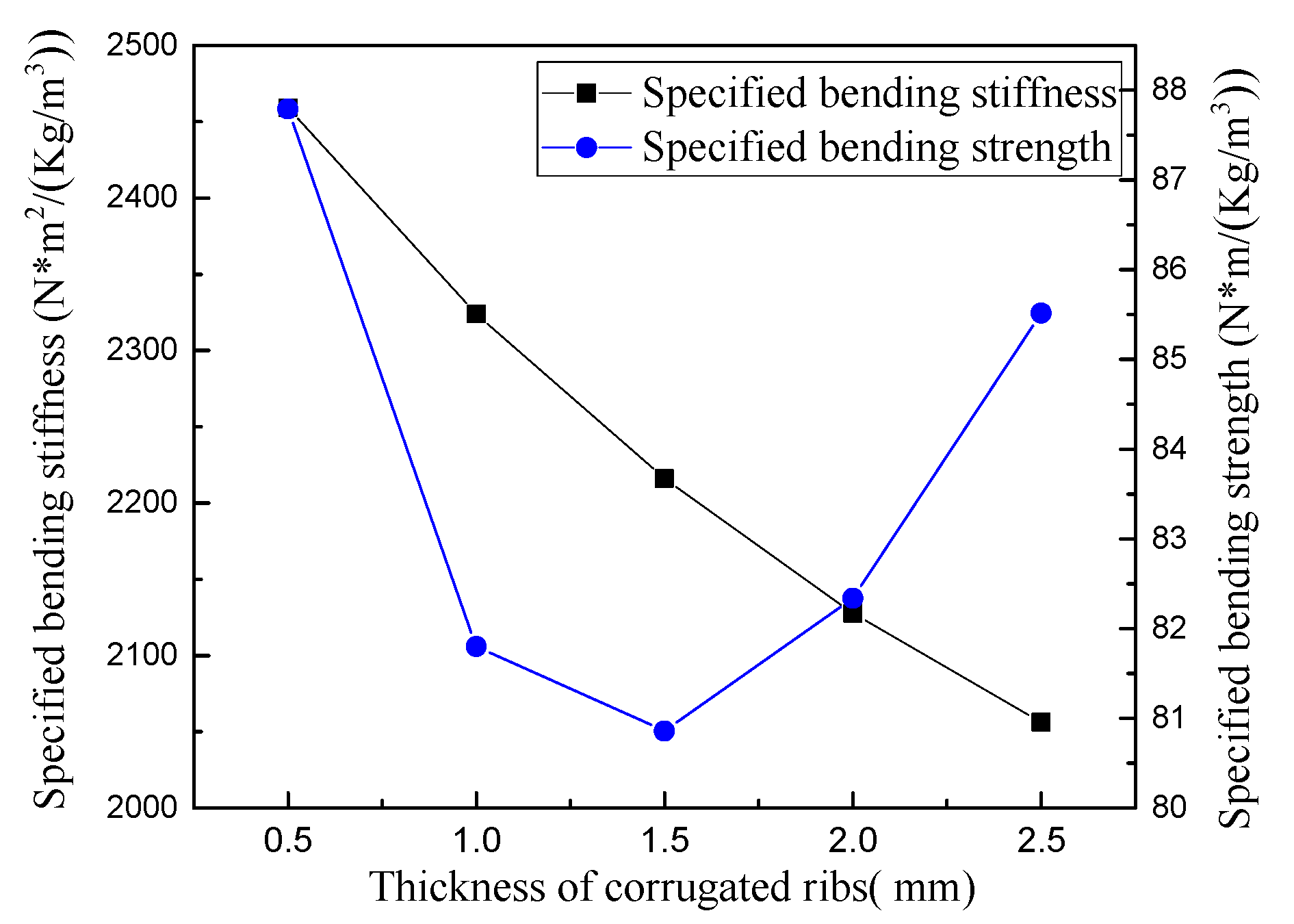
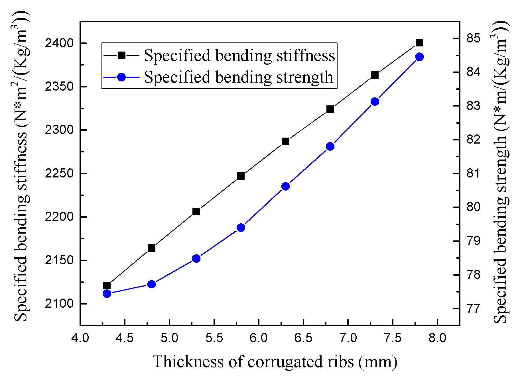
In order to reveal the influence of core parameters on specified bending stiffness and strength further, the intermediate diameter and the material of cores remain the same. The thickness and height of the corrugated cores were considered. As shown in Figure 11 and Figure 12, the smaller thickness of corrugated ribs and larger height of corrugated cores can improve the specified bending stiffness and strength of the sandwich cylinder. For variable core parameters, the failure modes are all skin failure, which is mainly caused by the matrix tension. Due to the effect of mass density, when the skin thickness is 1.5 mm, there is an inflection point in the specific bending strength curve shown in Figure 11. However, the influence of core parameters on the specified bending stiffness and strength are lower than that of the skin parameters. This is because the mass density of cores is greatly affected by the core parameters, which could balance the variation of stiffness and strength of the corrugated core sandwich cylinder.
5. Conclusions
A theoretically equivalent homogenization method for composite sandwich cylinders under pure bending was proposed to overcome the bending stiffness and strength calculation, which has good accuracy with the FE model.
Based on a homogeneous orthotropic layer hypothesis, the trapezoidal corrugated sandwich core was equivalent to a material with nine equivalent mechanical properties. Lekhnitskii’s theory based on a unified connection parameter method was introduced and applied in the equivalent composite sandwich cylinder. A case study shows that the developed Lekhnitskii theory is suitable for an arbitrary combination of winding layers with different angles or materials. The bending stiffness of the equivalent sandwich cylinder could be calculated.
By developing the user subroutine of UMAT, the numerical calculation results were in good agreement with the results of the proposed method. Further, according to the Hill–Tsai strength criterion and the maximum strain criterion, parametric study for specified bending stiffness and specified bending strength was done. The results show that the influence of core parameters on the specified bending stiffness and strength is lower than that of the skin parameters. Larger skin thickness and smaller winding angles could improve the specified bending stiffness and strength of the composite corrugated sandwich cylinders.
Author Contributions
Conceptualization, Y.L.; Data curation, F.G.; Formal analysis, F.G.; Funding acquisition, X.L.; Investigation, Y.L.; Project administration, X.Z.; Resources, F.G.; Software, M.L.; Supervision, X.L.; Validation, F.G.; Visualization, F.G.; Writing—original draft, Y.L.; Writing—review and editing, X.Z. All authors have read and agreed to the published version of the manuscript.
Funding
This research was funded by the Postgraduate Research & Practice Innovation Program of Jiangsu Province (KYCX18_1088), National Natural Science Foundations of China (No. 11772147), the Natural Science Foundation of Jiangsu Province, China (No. BK20200706), the Major University Science Research Project of Jiangsu Province, China (No. 20KJA460001), and The National Major Scientific Research Instrument Development Program (Major Program, No. 12027901).
Institutional Review Board Statement
Not applicable.
Informed Consent Statement
Not applicable.
Data Availability Statement
It was followed according to MDPI Research Data Policies.
Conflicts of Interest
The authors declare no conflict of interest.
References
- Gibson, L.J.; Ashby, M.F. Cellular Solids: Structure and Properties; Cambridge University Press: Cambridge, UK, 1997. [Google Scholar]
- Wadley, H.N.G.; Fleck, N.A.; Evans, A.G. Fabrication and structural performance of periodic cellular metal sandwich structures. Compos. Sci. Technol. 2003, 63, 2331–2343. [Google Scholar]
- Côté, F.; Deshpande, V.S.; Fleck, N.A.; Evans, A.G. The compressive and shear responses of corrugated and diamond lattice materials. Int. J. Solids. Struct. 2006, 43, 6220–6242. [Google Scholar] [CrossRef] [Green Version]
- Jiang, S.; Sun, F.; Fan, H.; Fang, D. Fabrication and testing of composite orthogrid sandwich cylinder. Compos. Sci. Technol. 2017, 142, 171–179. [Google Scholar] [CrossRef]
- Fan, H.L.; Jin, F.N.; Fang, D.N. Nonlinear mechanical properties of lattice truss materials. Mater. Des. 2009, 30, 511–517. [Google Scholar] [CrossRef]
- Liu, J.; Xiang, L.; Kan, T. The effect of temperature on the bending properties and failure mechanism of composite truss core sandwich structures. Compos. Part A Appl. Sci. Manuf. 2015, 79, 146–154. [Google Scholar] [CrossRef]
- Fan, H.; Fang, D.; Chen, L.; Dai, Z.; Yang, W. Manufacturing and testing of a CFRC sandwich cylinder with Kagome cores. Compos. Sci. Technol. 2009, 69, 2695–2700. [Google Scholar] [CrossRef]
- Fan, H.L.; Jin, F.N.; Fang, D.N. Mechanical properties of hierarchical cellular materials. Part I: Analysis. Compos. Sci. Technol. 2008, 68, 3380–3387. [Google Scholar] [CrossRef]
- Morozov, E.V.; Lopatin, A.V.; Nesterov, V.A. Finite-element modelling and buckling analysis of anisogrid composite lattice cylindrical shells. Compos. Struct. 2011, 93, 308–323. [Google Scholar] [CrossRef]
- Zheng, Q.; Jiang, D.; Huang, C.; Shang, X.; Ju, S. Analysis of failure loads and optimal design of composite lattice cylinder under axial compression. Compos. Struct. 2015, 131, 885–894. [Google Scholar]
- Xiong, J.; Ghosh, R.; Ma, L.; Vaziri, A.; Wang, Y.; Wu, L. Sandwich-walled cylindrical shells with lightweight metallic lattice truss cores and carbon fiber-reinforced composite face sheets. Compos. Part A Appl. Sci. Manuf. 2014, 56, 226–238. [Google Scholar] [CrossRef]
- Li, W.; Sun, F.; Wei, W.; Liu, D.; Zhang, X.; Li, M.; Fan, H. Fabrication and testing of composite corrugated-core sandwich cylinder. Compos. Sci. Technol. 2018, 156, 127–135. [Google Scholar] [CrossRef]
- Sun, F.; Fan, H.; Zhou, C.; Fang, D. Equivalent analysis and failure prediction of quasi-isotropic composite sandwich cylinder with lattice core under uniaxial compression. Compos. Struct. 2013, 101, 180–190. [Google Scholar] [CrossRef]
- Lekhnitskii, S.G. Theory of Elasticity of an Anisotropic Body; Mir Publisher: Moscow, Russia, 1981. [Google Scholar]
- Jolicoeur, C.; Cardou, A. Analytical solution for bending of coaxial orthotropic cylinders. J. Eng. Mech. 1994, 120, 2556–2574. [Google Scholar] [CrossRef]
- Xia, M.; Takayanagi, H.; Kemmochi, K. Bending behavior of filament-wound fiber-reinforced sandwich pipes. Compos. Struct. 2002, 56, 201–210. [Google Scholar] [CrossRef]
- Zhang, C.; Hoa, S.V. A limit-based approach to the stress analysis of cylindrically orthotropic composite cylinders (0/90) subjected to pure bending. Compos. Struct. 2012, 94, 2610–2619. [Google Scholar] [CrossRef]
- Zhang, C.; Hoa, S.V.; Liu, P. A method to analyze the pure bending of tubes of cylindrically anisotropic layers with arbitrary angles including 0° or 90°. Compos. Struct. 2014, 109, 57–67. [Google Scholar] [CrossRef]
- Libove, C.; Hubka, R.E. Elastic Constants for Corrugated-Core Sandwich Plates; Tech. Note 2289; National Advisory Committee for Aeronautics: Washington, DC, USA, 1951; Volume 105. [Google Scholar]
- Xia, Y.; Friswell, M.I.; Flores, E.I.S. Equivalent models of corrugated panels. Int. J. Solids. Struct. 2012, 49, 1453–1462. [Google Scholar] [CrossRef] [Green Version]
- Bartolozzi, G.; Pierini, M.; Orrenius, U.; Baldanzini, N. An equivalent material formulation for sinusoidal corrugated cores of structural sandwich panels. Compos. Struct. 2013, 100, 173–185. [Google Scholar] [CrossRef]
- Bartolozzi, G.; Baldanzini, N.; Pierini, M. Equivalent properties for corrugated cores of sandwich structures: A general analytical method. Compos. Struct. 2014, 108, 736–746. [Google Scholar] [CrossRef]
- Magnucka-Blandzi, E.; Magnucki, K. Transverse shear modulus of elasticity for thin-walled corrugated cores of sandwich beams. Theoretical study. J. Theor. Appl. Mech. 2014, 52, 971–980. [Google Scholar] [CrossRef] [Green Version]
- Magnucka-Blandzi, E.; Magnucki, K.; Wittenbeck, L. Mathematical modeling of shearing effect for sandwich beams with sinusoidal corrugated cores. Appl. Math. Model 2015, 39, 2796–2808. [Google Scholar] [CrossRef]
- Shaban, M.; Alibeigloo, A. Three-dimensional elasticity solution for sandwich panels with corrugated cores by using energy method. Thin-Walled Struct. 2017, 119, 404–411. [Google Scholar] [CrossRef]
- Zhang, Z.; Lei, H.; Xu, M.; Hua, J.; Li, C.; Fang, D. Out-of-plane compressive performance and energy absorption of multi-layer graded sinusoidal corrugated sandwich panels. Mater. Des. 2019, 178, 107858. [Google Scholar] [CrossRef]
- Ghahfarokhi, D.S.; Rahimi, G. An analytical approach for global buckling of composite sandwich cylindrical shells with lattice cores. Int. J. Solids. Struct. 2018, 146, 69–79. [Google Scholar] [CrossRef]
- Yadav, A.; Amabili, M.; Panda, S.K.; Dey, T.; Kumar, R. Forced nonlinear vibrations of circular cylindrical sandwich shells with cellular core using higher-order shear and thickness deformation theory. J. Sound Vib. 2021, 510, 116283. [Google Scholar] [CrossRef]
- Guo, J.; Xiao, Y.; Zhang, S.; Wen, J. Bloch wave based method for dynamic homogenization and vibration analysis of lattice truss core sandwich structures. Compos. Struct. 2019, 229, 111437. [Google Scholar] [CrossRef]
- Pydah, A.; Batra, R.C. Analytical solution for cylindrical bending of two-layered corrugated and webcore sandwich panels. Thin-Walled Struct. 2018, 123, 509–519. [Google Scholar] [CrossRef]
- Kolpakov, A.A.; Kolpakov, A.G. On the effective stiffnesses of corrugated plates of various geometries. Int. J. Eng. Sci. 2020, 154, 103327. [Google Scholar] [CrossRef]
- Buannic, N.; Cartraud, P.; Quesnel, T. Homogenization of corrugated core sandwich panels. Compos. Struct. 2003, 59, 299–312. [Google Scholar] [CrossRef] [Green Version]
- Yang, J.S.; Ma, L.; Schröder, K.U.; Chen, Y.L.; Li, S.; Wu, L.Z.; Schmidt, R. Experimental and numerical study on the modal characteristics of hybrid carbon fiber composite foam filled corrugated sandwich cylindrical panels. Polym. Test 2018, 68, 8–18. [Google Scholar] [CrossRef]
- Xiong, J.; Feng, L.; Ghosh, R.; Wu, H.; Wu, L.; Ma, L.; Vaziri, A. Fabrication and mechanical behavior of carbon fiber composite sandwich cylindrical shells with corrugated cores. Compos. Struct. 2016, 156, 307–319. [Google Scholar] [CrossRef] [Green Version]
- Mohammadi, H.; Ziaei-Rad, S.; Dayyani, I. An equivalent model for trapezoidal corrugated cores based on homogenization method. Compos. Struct. 2015, 131, 160–170. [Google Scholar] [CrossRef]
- Gu, F.; Chen, L.; Zhu, X.; Lu, X.; Fang, D. Fabrication and uniaxial compression mechanical behavior of composite corrugated-core sandwich cylinder with thin-wall metal liner. Mech. Adv. Mater. Struct. 2020, 1–14. [Google Scholar] [CrossRef]
- Gu, F.; Yuan, X.; Zhu, X.; Lu, X.; Fang, D.; Li, L. Numerical study of composite laminates subjected to low-velocity impact using a localized damage algorithm of Puck’s 3D IFF criterion. Eng. Fract. Mech. 2020, 228, 106901. [Google Scholar] [CrossRef]
Figure 1.
A composite tube under pure bending load.

Figure 2.
A corrugated sandwich structure with trapezoidal core. (a) Section of the corrugated sandwich cylinder. (b) A cell of the trapezoidal corrugated core (x-axis corresponds to the machine-direction, y-axis is denoted cross-direction, and z-direction is perpendicular to the panel.).
Figure 2.
A corrugated sandwich structure with trapezoidal core. (a) Section of the corrugated sandwich cylinder. (b) A cell of the trapezoidal corrugated core (x-axis corresponds to the machine-direction, y-axis is denoted cross-direction, and z-direction is perpendicular to the panel.).

Figure 3.
Geometries of half a period of the trapezoidal corrugated core.

Figure 4.
Loads and forces acting on the centerline of the corrugation part A–B.

Figure 5.
Shear deformation of the core sheet specimen in the equivalent volume.

Figure 6.
Homogenization method of the corrugated core sandwich cylinders. (a) Section of the sandwich cylinder, (b) periodic cells, (c) homogenization cells.
Figure 6.
Homogenization method of the corrugated core sandwich cylinders. (a) Section of the sandwich cylinder, (b) periodic cells, (c) homogenization cells.

Figure 7.
The finite element semi model after meshed. (Length of sandwich cylinder is 2000 mm).

Figure 8.
The numerical result for the axial stress component.

Figure 9.
Specified bending stiffness with variable skin thickness and winding angle.

Figure 10.
Specified bending strength with variable skin thickness and winding angle.

Figure 11.
Specified bending stiffness and strength with variable thickness of corrugated ribs ( = 6.8 mm, = 2.4 mm, 2 × p = 12.56 mm, = ±15°).
Figure 11.
Specified bending stiffness and strength with variable thickness of corrugated ribs ( = 6.8 mm, = 2.4 mm, 2 × p = 12.56 mm, = ±15°).

Figure 12.
Specified bending stiffness and strength with variable height of corrugated cores ( = 1 mm, = 2.4 mm, 2 × p = 12.56 mm, = ±15°).
Figure 12.
Specified bending stiffness and strength with variable height of corrugated cores ( = 1 mm, = 2.4 mm, 2 × p = 12.56 mm, = ±15°).


Table 1.
The geometric parameters of the sandwich cylinder.
| Parameters | Dimensions |
|---|---|
| Inner radius, | 95 mm |
| Inner skin thickness, tfi | 1.6 mm |
| Winding angles of inner skin, | [90/0] |
| Outer skin thickness, tfo | 1.6 mm |
| Winding angles of outer skin, | [90/0] |
| Cell number | 50 |
| Height of cores, hc | 6.8 mm |
| Angle of corrugation, θ | 53.57° |
| Corrugated rib thickness, tc | 1 mm |
| Length of upper horizontal part, 2 × p1 | 2 mm |
| Length of below horizontal part, 2 × p3 | 2 mm |
| Length of trapezoidal core, 2 × p | 12.56 mm |
Table 2.
Material Properties.
| Material Properties | Carbon Fiber/Epoxy Resin | Glass Fiber/Epoxy Resin |
|---|---|---|
| E11/MPa | 1.55 × 10⁵ | 6.0 × 10⁴ |
| E22 = E33/MPa | 1.21 × 10⁴ | 1.1 × 10⁴ |
| G23/MPa | 3.2 × 10³ | 3.2 × 10³ |
| G13 = G12/MPa | 4.4 × 10³ | 7.6 × 10³ |
| v12 = v13 | 0.248 | 0.26 |
| v23 | 0.458 | 0.458 |
Table 3.
The equivalent parameters for trapezoidal profile geometries.
| Ex (MPa) | Ey (MPa) | vyx | Gxy (MPa) | Ez (MPa) | Gxz (MPa) | Gyz (MPa) | vyz | vxz |
|---|---|---|---|---|---|---|---|---|
| 295.74 | 17,948.8 | 0.33 | 6747.68 | 453.30 | 3314.44 | 3420.03 | 0.33 | 0.771 |
Table 4.
The results of the equivalent homogenization theoretical model and the FE model.
| Results | /MPa | /MPa | |
|---|---|---|---|
| FE model | 9.356 × 10⁻⁶ | 11.647 | 166.4 |
| Theoretical method | 9.672 × 10⁻⁶ | 11.118 | 158.0 |
| Relative errors | −3.34% | 4.54% | 5.05% |
Table 5.
Material property for skins and cores.
| Winding Layers (Skins) | E1 = 158 GPa, E2 = E3 = 14.4 GPa; u12 = u13 = 0.413; u23 = 0.5; G12 = G13 = 4.4 GPa; G23 = 3.7 GPa; XT = 1850 Mpa; XC = 1470 MPa; YT = 29 MPa; YC = 140 MPa; S12 = S13 = S23 = 65 Mpa; ρ = 1.7 g/cm3 | |
| Cores | Standard aluminum alloy | E = 71 GPa, = 0.33, X = = 240 MPa, ρ = 2.8 g/cm3 |
| Carbon fiber woven composite with [0/90]ns | E = 54.5 GPa, = 0.06, G = 4400 MPa XT = XC = 473 MPa, ρ = 1.7 g/cm3 | |
Publisher’s Note: MDPI stays neutral with regard to jurisdictional claims in published maps and institutional affiliations. |
© 2021 by the authors. Licensee MDPI, Basel, Switzerland. This article is an open access article distributed under the terms and conditions of the Creative Commons Attribution (CC BY) license (https://creativecommons.org/licenses/by/4.0/).
Share and Cite
MDPI and ACS Style
Liu, Y.; Gu, F.; Li, M.; Lu, X.; Zhu, X. An Equivalent Homogenization Theoretical Method for Composite Sandwich Cylinders Subjected to Pure Bending. Symmetry 2021, 13, 2225. https://0-doi-org.brum.beds.ac.uk/10.3390/sym13112225
AMA Style
Liu Y, Gu F, Li M, Lu X, Zhu X. An Equivalent Homogenization Theoretical Method for Composite Sandwich Cylinders Subjected to Pure Bending. Symmetry. 2021; 13(11):2225. https://0-doi-org.brum.beds.ac.uk/10.3390/sym13112225
Chicago/Turabian StyleLiu, Yang, Fuwei Gu, Mingxuan Li, Xiaofeng Lu, and Xiaolei Zhu. 2021. "An Equivalent Homogenization Theoretical Method for Composite Sandwich Cylinders Subjected to Pure Bending" Symmetry 13, no. 11: 2225. https://0-doi-org.brum.beds.ac.uk/10.3390/sym13112225
Note that from the first issue of 2016, this journal uses article numbers instead of page numbers. See further details here.