
Vibro-Acoustic Energy Transmission Analysis of the Acoustic Cavity with Multiple Partial Partitions


1
College of Marine Engineering, Dalian Maritime University, Dalian 116026, China
2
College of Power and Energy Engineering, Harbin Engineering University, Harbin 150001, China
*
Author to whom correspondence should be addressed.
Symmetry 2021, 13(12), 2257; https://0-doi-org.brum.beds.ac.uk/10.3390/sym13122257
Submission received: 27 October 2021
/
Revised: 12 November 2021
/
Accepted: 12 November 2021
/
Published: 26 November 2021
Abstract
:The general dynamic characteristics of the acoustic cavity with multiple partial partitions are presented in this thesis. A theoretical model has been developed for predictions, and several configurations are analyzed. To describe the apertures on the interface of subcavities, the virtual air panel assumption is introduced into the improved Fourier series system. The governing equations of the coupling system are derived by using the energy principle. The results obtained with the proposed model are firstly compared with the numerical calculations based on the finite element method (FEM). Subsequently, a configuration made up from a rigid cavity partitioned by a partial steel panel has been specifically built, and the forced responses of the coupling system have been measured for comparison and model validation. The present results are excellent over most of the studied frequency range. Furthermore, the visualizations of the interior sound intensity field of the acoustic cavity with three partial partitions under different frequencies are researched to illustrate the energy transmission paths and vibro-acoustic coupling mechanism of the complicated system. The obtained results are believed to be helpful in the optimal design of the vibro-acoustic coupling system with optimal sound insulation capacity.
1. Introduction
Flexible panel structure and acoustic cavity coupling systems can be found in various engineering fields, such as marine and astronautical engineering. A clear understanding of the vibro-acoustic coupling and energy transmission mechanism is the necessary prerequisite and foundation to develop effective means of noise and vibration control of such complicated systems. To deal with this problem, several theoretical models have been introduced to predict and analyze the dynamic characteristics of vibro-acoustic coupling systems.
Dowell and Voss first studied the modal response of a coupled panel–cavity system with regard to the modal characteristics of the uncoupled structural and acoustic systems [1]. Then, Pan et al. focused on the active control technology of the coupling systems to reduce the noise transmission through a panel into a cavity [2,3]. They also investigated the effect of the coupling on the medium-frequency response of the acoustic field in a panel–cavity system on the basis of the classical modal coupling method [4,5]. Lately, the convergence criteria of the method were revealed by Hu et al. through numerical analyses [6]. Kim and Brennan presented a compact matrix formulation to analyze the vibro-acoustic coupled system by the impedance and mobility methods [7]. Li and Cheng employed the combined integro-modal method to investigate the coupling characteristics of a flexible panel backed by an irregular acoustic cavity [8,9]. Du et al. proposed the full coupled theoretical model to analyze the vibro-acoustic performance of the panel–cavity coupling system [10,11]. The improved Fourier series method was employed to address the impedance discontinuity in the vibro-acoustic research. Xie et al. presented the panel–cavity coupling system model by developing the variational method to predict the vibration and sound responses of the coupled car-like model [12]. However, these studies were restricted to the relatively simple panel–cavity systems with the interaction between structures and acoustic fields.
Unlike the most conventional vibro-acoustic coupling system, in many practical applications, apertures placed on the boundary of the acoustic fields are needed to satisfy the ventilation, heat exchange, and/or the technology requirements. Through the apertures, there is a direct interaction between different acoustic fields. Thus, it is of great importance to investigate the influence of the apertures on the general dynamic characteristics and energy transmission mechanism of the coupling system.
The early research of apertures was performed without taking into account the thickness of the boundaries. For example, Spence presented the diffraction of plane sound waves by circular apertures, as the size of the aperture is of the same order of magnitude as the wavelength [13]. Hongo and Serizawa evaluated the field diffracted by a rectangular aperture in the infinitely baffle with the method of the Kobayashi potential by considering two kinds of eigenfunction expansions [14]. Thereafter, Wilson and Soroka obtained the approximate transmission loss of a circular aperture in a rigid wall of finite thickness by postulating rigid, massless, infinitely thin plane pistons at each end of the aperture [15]. Sauter and Soroka investigated the sound transmission between two reverberant rooms through a connecting rectangular aperture by the same theory [16]. Park and Eom examined the acoustic scattering of a rectangular aperture in the infinitely baffle using the radiation impedance concept [17]. Sgard et al. predicted the transmission loss of rectangular and circular apertures based on the expansion of the wave field inside the aperture in terms of propagating and evanescent acoustic modes, in which the modal radiation impedance matrix of the aperture was calculated numerically [18]. The experimental validation of this numerical method based on the modal approach was further presented by Trompette et al. [19]. Most of the studies were based on plane wave approximation; the assumption could be valid below its cut-off frequency and has a certain gap with the actual existence.
In the aspect of the sound transmission between two acoustic fields connected through apertures, Seybert et al. solved the coupled interior/exterior boundary value problem using the boundary element method (BEM) [20]. Pierce et al. formulated the integral matrix of the sound radiation impedance of the square aperture on rigid enclosure boundaries [21]. Tong and Tang investigated the acoustical performance of the plenum windows installed on a building facade by means of experimental works to prevent noise pollution [22]. Pàmies et al. analyzed the sound radiation from an aperture on the rigid wall of a rectangular cavity both theoretically and experimentally [23]. The effects of the radiation behavior of the aperture for the interior acoustic field had been studied as the complex admittance of the walls. Poblet-Puig et al. developed a modal model that can be used to perform predictions of the sound transmitted through apertures connecting rooms of finite dimension [24].
Other models focused on the influence of the aperture on the panel–cavity system in which the boundary conditions of the enclosed acoustic field consist of the flexible panels and the apertures. This led to the interaction between different fields, which can be both structural and acoustic. Kim and Kim studied the physical coupling phenomena of a two-dimensional partially opened plate–cavity system to understand the coupling mechanism of a generally coupled system [25,26]. Nearfield acoustic holography was used to perform the visualization of the acoustic fields experimentally. Seo and Kim developed a model of the finite space and semi-infinite space separated by two flexible structures and one opening and predicted the energy distribution and energy flow of the vibro-acoustic coupling system [27]. Yu et al. firstly considered thin apertures involved in complex vibro-acoustic coupling systems as an equivalent structural component to investigate the sound transmission between acoustic media through the interface consisting of both structures and apertures using sub-structuring modeling techniques [28,29]. Apparently, less effort has been made to the comprehensive model where the structural transmission path is compatible with the acoustic transmission path between different acoustic fields.
Therefore, the aim of this paper is to develop an analytical vibro-acoustic model of the cavity partitioned by multiple partial partitions for attaining a deep understanding of the energy transmission mechanisms. The virtual air panel assumption is introduced into the improved Fourier series system to simulate the acoustic interface of subcavities. By using the energy principle, the governing equations of the vibro-acoustic coupling system are derived first. Afterward, the verification with the FEM and experimental works is conducted to validate the accuracy of the present approach. Finally, the sound intensity fields of the cavity with three partial partitions are predicted for identifying the energy transmission mechanisms of the coupling system.
2. Model Description and Formulation
2.1. Problem Definition
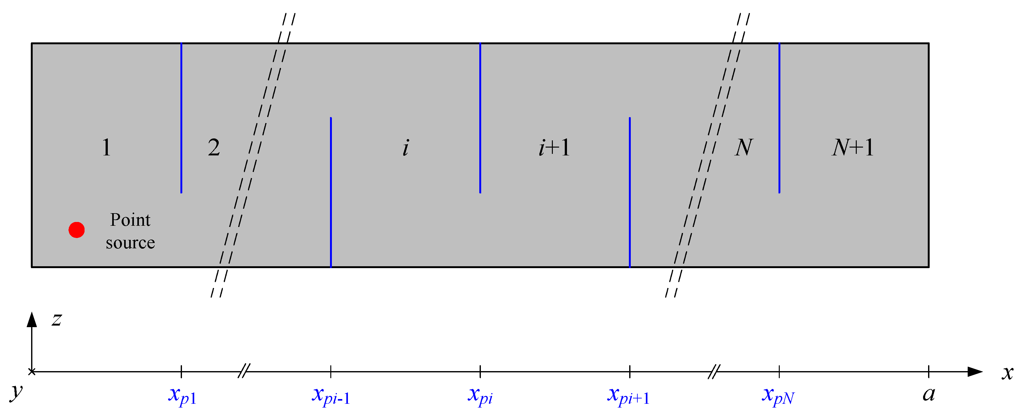
The geometry of the presented problem is shown in Figure 1. The acoustic cavity with dimensions of a × b × h comprises N + 1 subcavities separated by N partial partitions. The side walls of the cavity are all rigid. The interfaces between two neighboring subcavities are composed of partial partitions and apertures. The partitions are considered as flexible panels with a general elastically restrained boundary condition on three edges that attached to the side walls of the cavity and free boundary condition on the remaining one edge. The two neighboring subcavities can be interacted through the apertures and the bending vibration of the panels.
2.2. Field Variable Expansions
According to the dynamic characteristics, the original domain can be divided into subcavities, panels, and apertures. The three kinds of subdomains are coupled with each other.
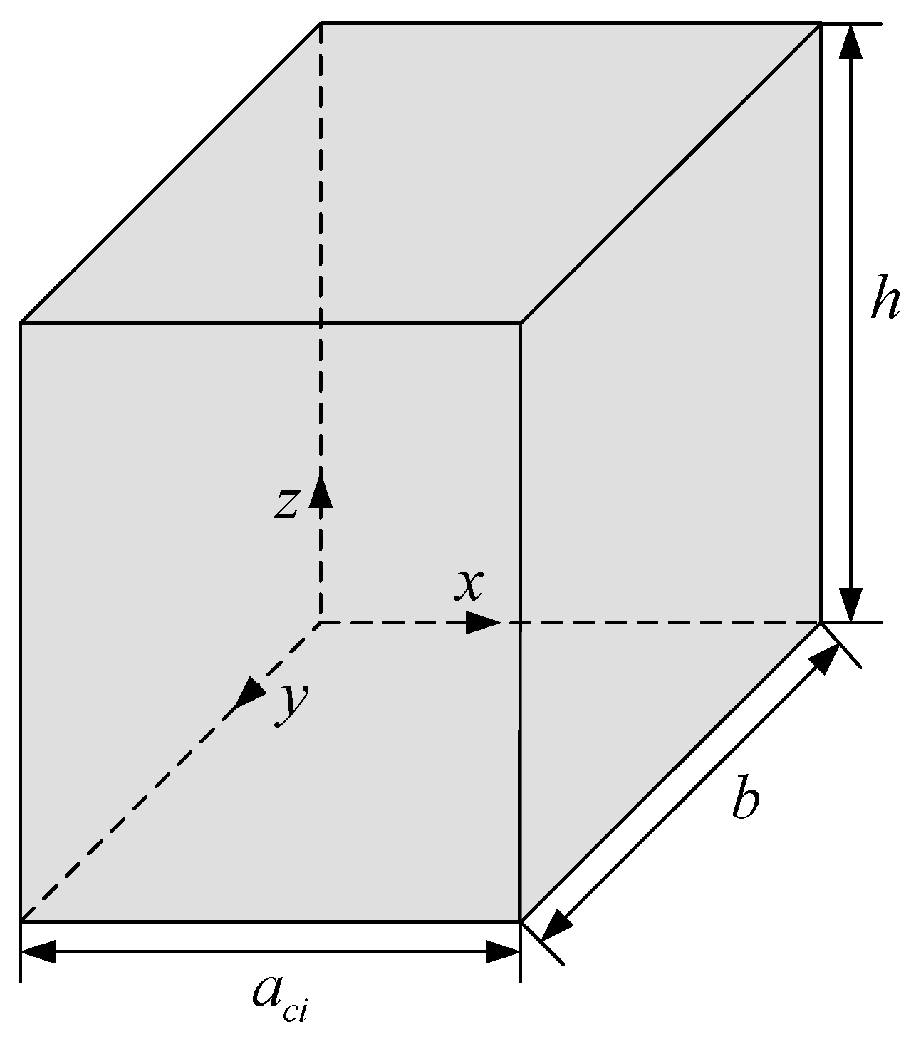
The three-dimensional acoustic cavity in Figure 2 is the fundamental subdomain for the proposed vibro-acoustic coupling model. The dimensions of the subcavities are aci × b × h, where i = 1, …, N + 1. The subcavity at the far left of the model is denoted as c1, and the right side wall of c1 is covered by the panel p1 and the aperture a1. The subcavity at the far right of the model is denoted as cN+1, and the left side wall of cN+1 is covered by pN and aN. Likewise, the left and right side walls of ci are covered by the panels pi−1, ai−1 and pi, ai, respectively.
In order to overcome the discontinuity of the acoustic boundaries, the improved Fourier series method that expanded the sound pressure on the basis of the three-dimensional Fourier series and introduced the supplementary functions on the non-rigid boundary walls is employed. For this study, there are five rigid walls in c1 and cN+1, the sound pressure of these two subcavities can be described as
The sound pressure of other subcavities with four rigid walls are
where , , and the supplementary functions are
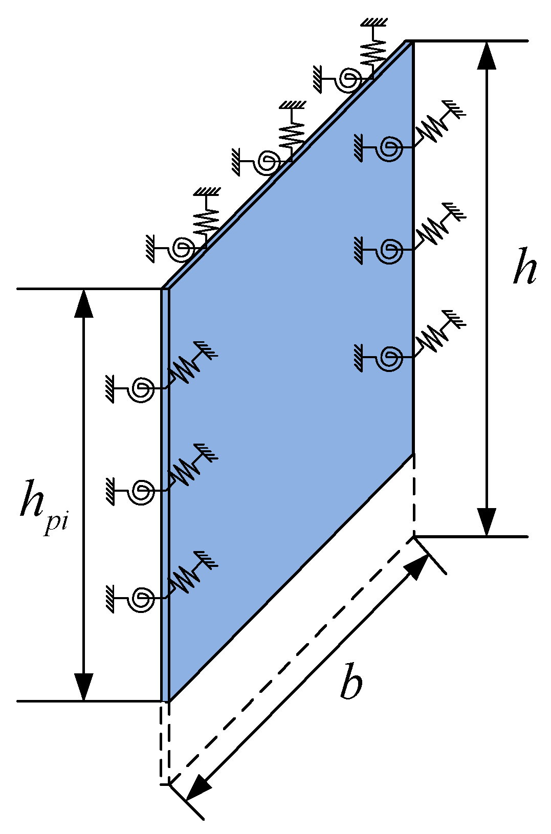
For the flexible panel shown in Figure 3, the length, width, and thickness of the panel are denoted as b, hpi, and δpi, respectively. Using the improved Fourier series method, the transverse displacement of the panel is given by
where , , and the supplementary functions are
Considering the apertures located on the interfaces between two neighboring subcavities, the virtual air panel assumption is introduced to formulate the apertures as the flexible air panel with small thickness δai and width hai, where hai = h − hpi. The field variable expansion for the transverse displacement of the aperture can be written as
where and . The supplementary functions of the aperture can be directly obtained from Equation (8) by replacing the subscript pi with ai.
2.3. Energy Principle
The energy principle will be used to drive the governing equation for the proposed coupling system. This can be done by means of the Lagrangian equation of every subdomain.
Firstly, for the acoustic subcavities, the Lagrangian equations of the subcavities are defined as
where the potential energy and kinetic energy of the ith subcavity are respectively derived by
where ρ0 and c0 are the mass density and sound speed of the acoustic medium in the cavity, respectively.
The work done due to the vibration of the panels and apertures are respectively calculated from
The work done by the point source is
where Qs is the volume velocity and δ(x, y) is the Dirac delta function.
The panels and apertures of the coupling system can both be treated as two-dimensional flexible structures in the proposed model. As a result of the significant difference between the impedances of the panels and apertures, the coupling between these two types of subdomains is so weak that it can be neglected. Therefore, the Lagrangian equations of the panels and apertures can be defined as
where the potential and kinetic energies of the ith panel are derived by
where , , , , and denote the flexural rigidity, Young’s modulus, the thickness, the Poisson’s ratio, and the mass density. and are the stiffness of translational and rotational springs along the z = 0 edge. The parameter describing the properties of the apertures can be obtained by replacing the subscript pi with ai.
According to energy conservation theory, the work done by the sound pressure acting on the panels and apertures is derived from
Substituting the field functions of the subdomains into each Lagrangian function, and following the Rayleigh–Ritz procedure, the matrix equations are able to be obtained.
where K and M denote the stiffness and mass matrixes, respectively. C denotes the coupling matrixes. P denotes the Fourier series coefficient vector of the subcavities. W denotes the Fourier series coefficient vector of the panels and apertures.
Then, the matrix equation of the vibro-acoustic coupling system can be constructed by combining the above equations.
where E is a vector that contains all the unknown Fourier expansion coefficients in the field functions of the subdomains and F is the excitation vector.
On one hand, the modal parameters of the coupled vibro-acoustic system can be obtained by solving the normal eigenvalue problem in Equation (26) by setting the loading vector on the right-hand side of the equation to zero. On the other hand, all the unknown Fourier series coefficients of the field functions of the subdomains can be determined by solving Equation (26) directly. On performing the analysis of the coupling system, the structural velocities and the acoustic pressures at any point inside the coupling system are obtained. Subsequently, on post-processing the data, certain other parameters representing the measure of the energy transmission such as the sound intensity can be calculated from
where is the particle velocity inside the sound field, and * donates the complex conjugate.
3. Validation of the Theoretical Modeling
To verify the performance of the developed vibro-acoustic coupling model, the dynamic characteristics of the coupling system are solved through the proposed model and FEM. In addition, a comparison of the theoretical and experimental results for the vibro-acoustic coupling system is done in the subsequent section. In all the examples shown here, the air in the acoustic cavity is assumed to have parameter values of c0 = 340 m/s and ρ0 = 1.21 kg/m unless otherwise specified.
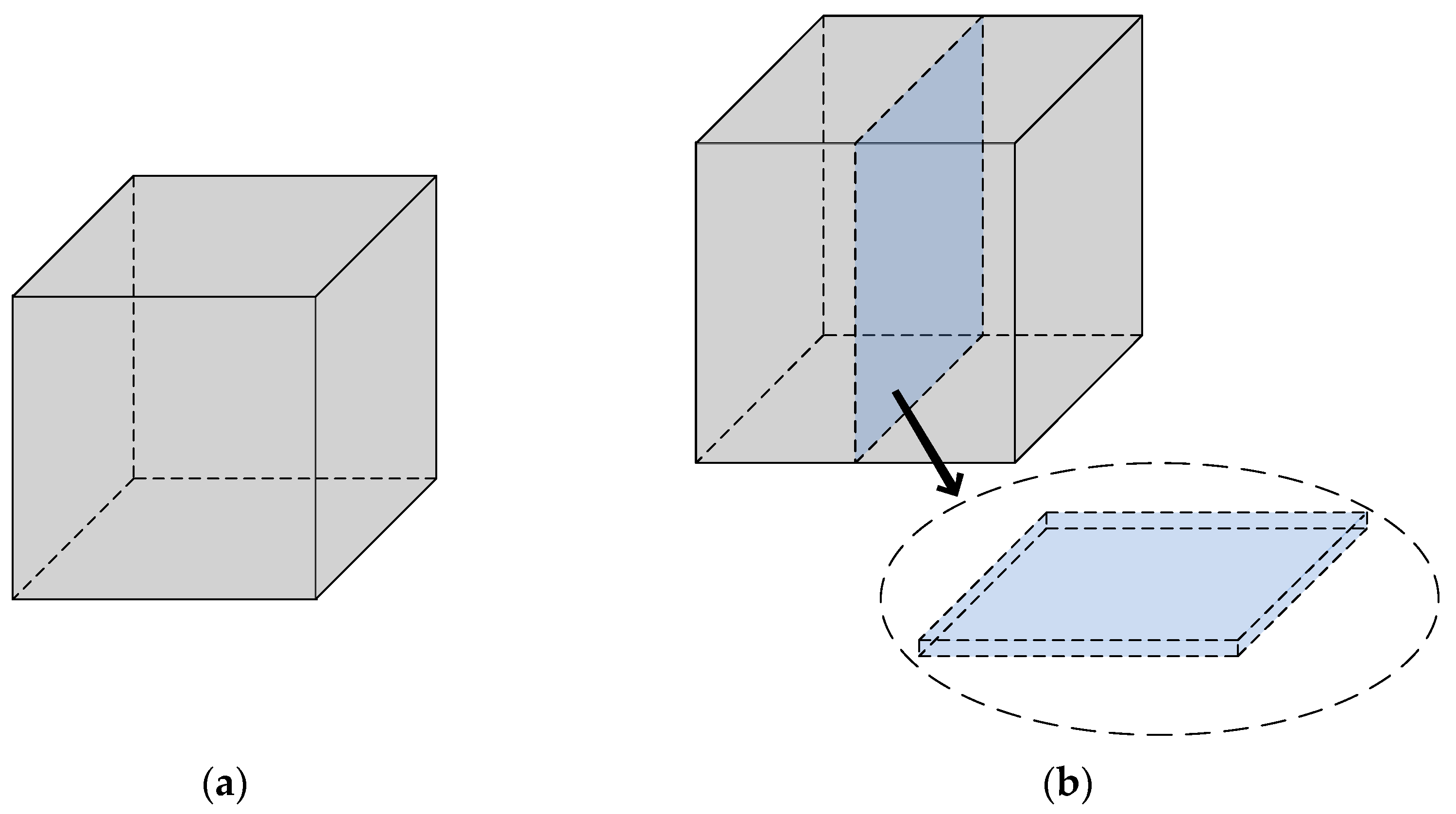
First of all, the classical rigid-walled rectangular cavity model with dimensions of 1 m × 1 m × 1 m shown in Figure 4a was utilized as a benchmark. The cavity was divided by a virtual air partition with a thickness of 0.1 mm at x = 0.5 m inside the cavity, as depicted in Figure 4b. The system can be partitioned into two cavities and an air panel. The air partition introduced in this study served the purpose of demonstrating the virtual air panel assumption effectiveness. As we all know, the exact values for the natural frequencies of a rigid-walled cavity are calculated from
where nx, ny, and nz denote the modal orders in x, y, and z directions, respectively. Table 1 shows the comparison of the first eight natural frequencies of the rigid-walled cavity from the present method and the analytical results. The excellent agreement between the two predictions for the first eight modes partially indicates the effectiveness and accuracy of the proposed theoretical model.
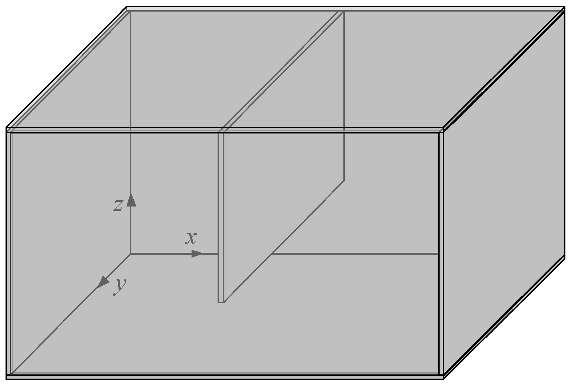
Further, we considered a partial rigid partition placed in the middle of the cavity with dimensions of 1 × 1 × 1 m3, as shown in Figure 5. Applying the theoretical model described in Section 2, the cavity can be partitioned into two subcavities and a partial aperture. The natural frequencies of the coupling system with a varying width of the aperture are listed in Table 2. The results correspond to the width of the aperture ha = 0.2 m, 0.4 m, 0.6 m, and 0.8 m respectively. The comparison results are calculated by FEM.
As can be seen in the preceding table, the agreement between the modal frequencies obtained with both calculation methods for different widths of the aperture is very good. This comment is also valid in the forced responses of the coupling system. To calculate the airborne sound insulation, a harmonic volume point source with volume velocity Q0 = 2 × 10⁻⁵ m3/s is placed in the cavity at position (0.1, 0.1, 0.1) m. Figure 6 shows the comparison of the sound pressure responses of the coupling system at positions (0.3, 0.4, 0.5) m and (0.9, 0.9, 0.9) m from both the present model and FEM.
It is also observed that the analytical results predicted from the proposed theoretical model match very well with the numerical results obtained by FEM. The difference found in the magnitude of the curves is small and mainly caused by the different introduced mechanisms of the damping ratio. These comparison works imply that the virtual air panel assumption is acceptable to derive an accurate dynamic model of the vibro-acoustic coupling system and validate the quality of the predictions done through the present model.
4. Experimental Work
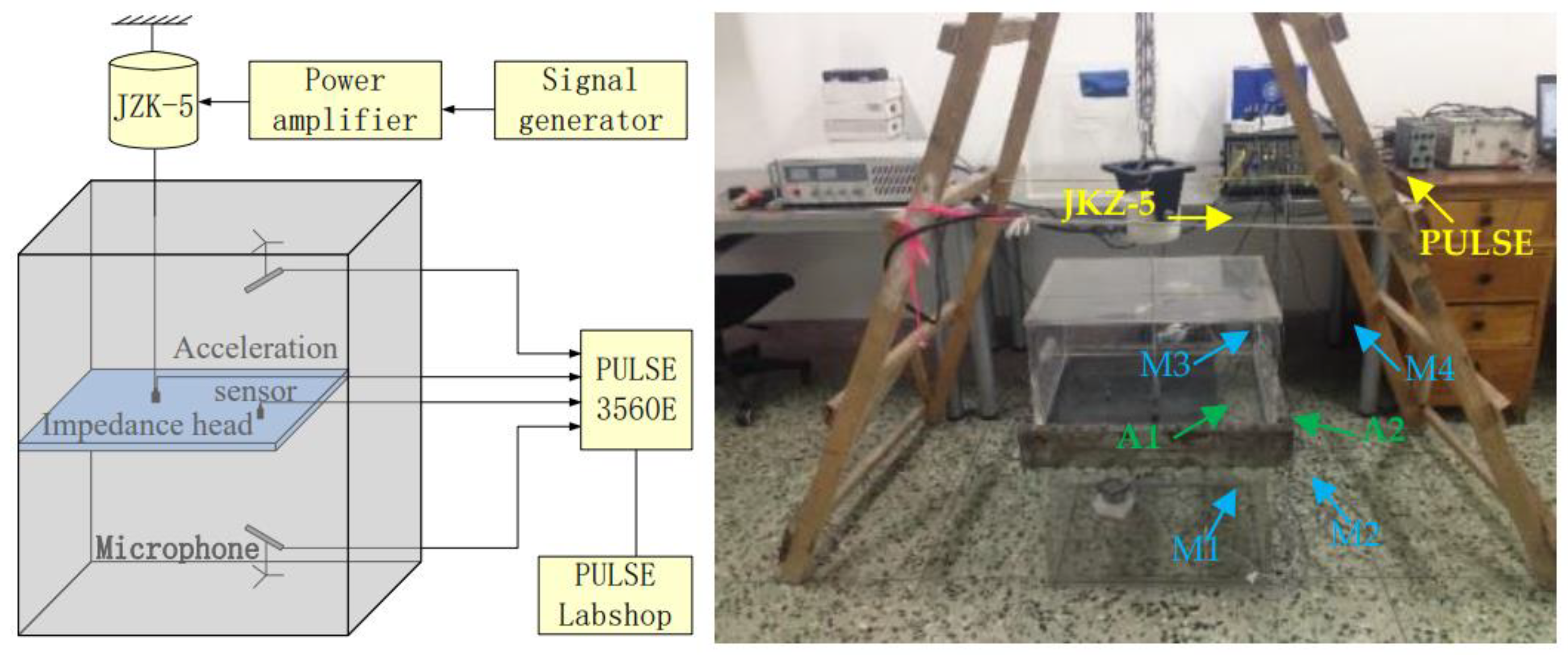
In this section, relevant experimental works are performed on the vibro-acoustic coupling system. The experimental arrangement is the rigid acoustic cavity with a partial flexible partition illustrated in Figure 7. The top and bottom sub of the cavity, i.e., c1 and c2 have a dimension of 0.5 × 0.4 m2 with c1 and c2 being 0.38 m and 0.28 m height, respectively. The experimental setup was placed in a laboratory room. To isolate the environmental effect, the side walls of two cavities are made of acrylic glass with a thickness of 15 mm to simulate the rigid boundaries except for the interfaces of the cavities and the flexible partition/aperture. The flexible panel with dimensions of 0.4 × 0.4 × 0.002 m3 is clamped along three edges and free for the rest of one edge. It is made up of steel with Young’s modulus of 210 GN/m, a mass density of 7800 kg/m, a Poisson ratio of 0.3, and a modal damping ratio assumed to be 0.002. A pair of square steel flanges are made by the mechanical process to connect the acoustic cavities and the panel structure. To guarantee the clamped boundary condition, thirty-eight bolts are used to fix three edges of the panel through two steel flanges.
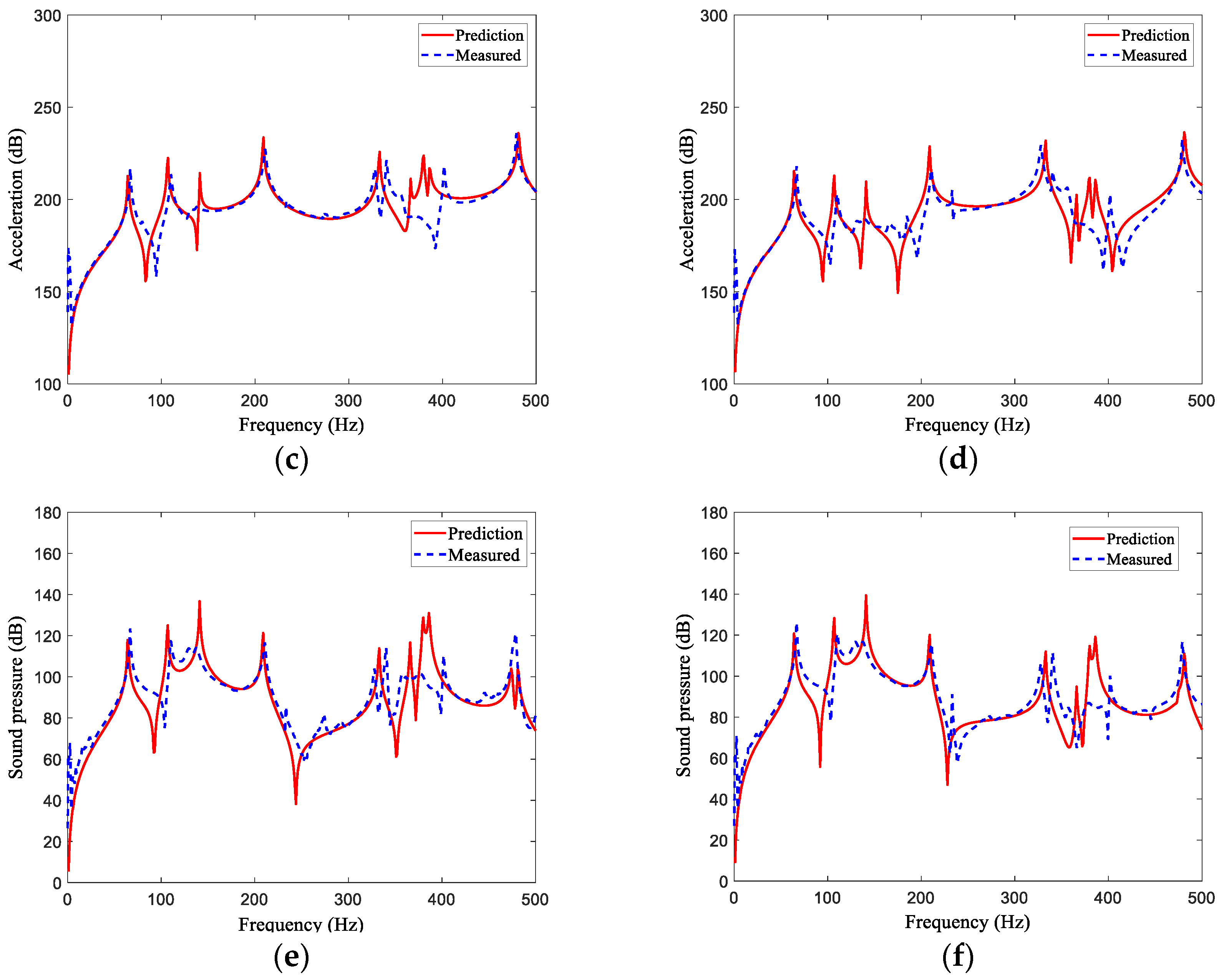
In measuring the transfer functions of the coupling system, a vibrator (JZK-5) is employed to produce structural excitation. The vibrator is suspended in the experimental system by soft springs. The springs and vibrator construct a single-freedom vibration system. Since low stiffness leads to low frequency, the output power of the vibration is supposed to be totally acted on the coupling system. The vibrator is supplied with a broadband signal of 1–500 Hz for vibrating the panel. To measure the external force signal, an impedance head (B&K2635) is placed at the end of the excitation bar, which is located at the position (0.246, 0.203, 0.380) m. Two acceleration sensors (B&K4508B) and four microphones (B&K type4943) are used to test the acceleration signal and pressure signal, respectively. All the signals are digitized by the multi-channel data acquisition system (PULSE 3560D) at a sufficient sampling rate of 16 KHz. The frequency response functions for the pressure and acceleration can be determined by dividing by the force signal. A comparison of the theoretical predictions and experimental measurements for the pressures and accelerations of the acoustic cavity with a partial flexible partition is shown in Figure 8.
It can be found that the experimental measurements agree reasonably well with the theoretical predictions in the frequency range, except that some measured resonance peaks appear offset. The theoretical curve is closer to the experimental result in the lower frequency range than in the higher frequency range. This is because the simplified model disregards the exterior acoustic and vibration field and the damping effect becomes larger as the frequency increases. The results suggest that the proposed theoretical model is well replicated in the experiment works. For the slight difference, this is understandable in that there are significant energy dissipation mechanisms and a dimensional error in the experiment, which are excluded from theory. Further improvements in modeling of the external excitation and/or the structural boundary conditions could minimize the difference seen in response curves. In any case, the obtained agreement in the general trend of the results and the order of magnitude is satisfactory.
5. Results and Discussions
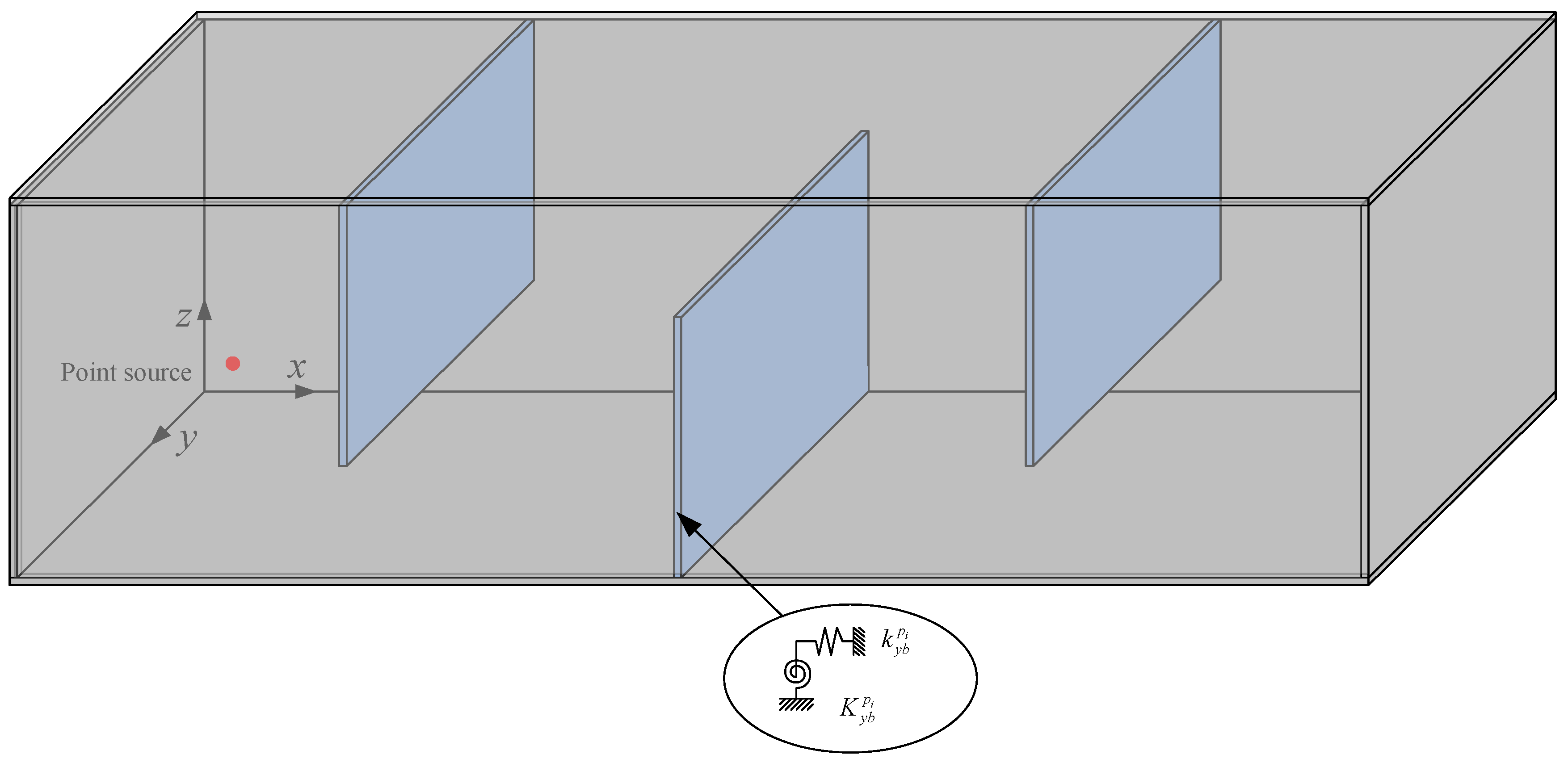
Based on the proposed theoretical model, the dynamic performance of the acoustic cavity with multiple partial partitions will be investigated and discussed. The coupling system consists of three flexible panels symmetrically placed inside a rigid cavity with the dimension of 2 × 1 × 1 m3, as shown in Figure 9. The width of the panels made of steel along the z-axis is 0.8 m and the thickness is 0.003 m, and the general boundary conditions are taken into account.
The natural frequencies of the coupling system are shown in Table 3. Three types of boundary conditions are involved: the elastically restrained represented by E in which the translational and rotational restraining coefficients are set to 103, the simply supported represented by S, and the clamped represented by C. The table shows that for the flexible partitions with different boundary conditions, the present results for the natural frequencies of the coupling system and FEM numerical results agree well. Compared with FEA, the present method can be easily extended to the complex vibro-acoustic coupling system consisting of different subdomain components without much modification. Therefore, the method is more suitable for parametric study, sensitivity and uncertainty analysis, and design optimization. The results also show that the first six modes of the coupling system are distributed by the panels and change significantly with the different boundary conditions.
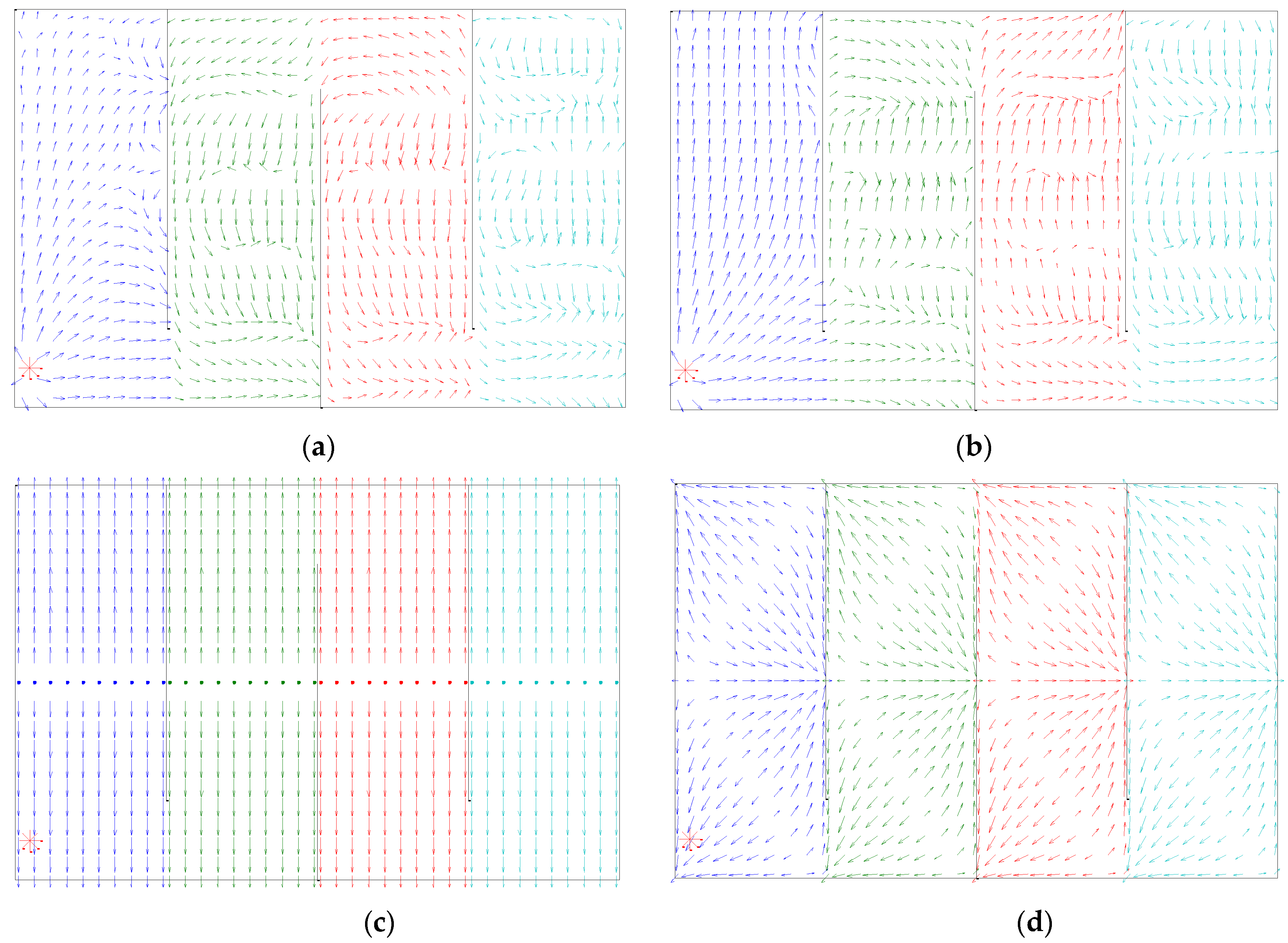
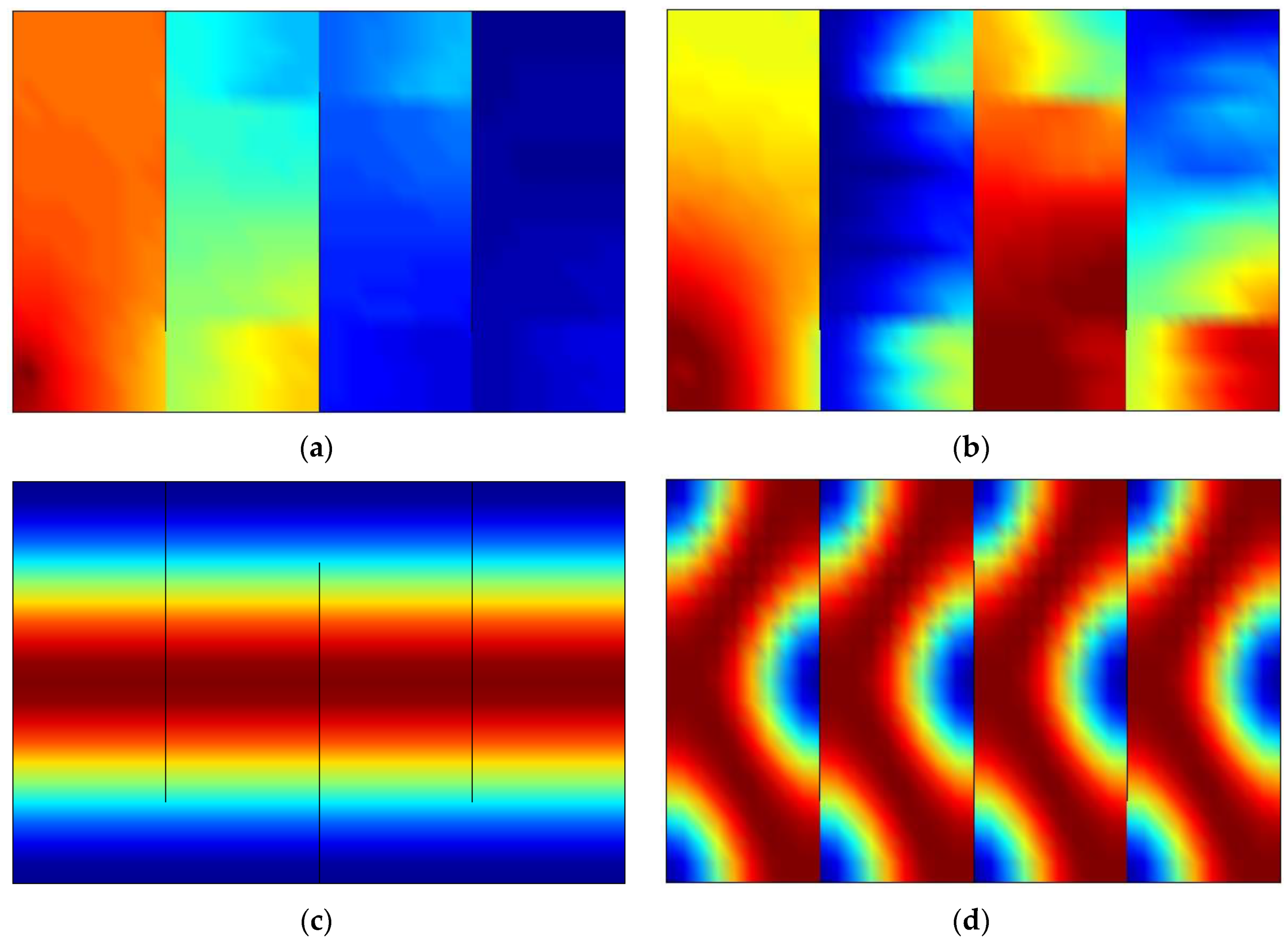
As mentioned earlier, the structural and the acoustic field functions of the coupling system can be directly obtained through the proposed theoretical model. Then, the dynamics and energy transmission characteristics of the acoustic cavity with three simply supported partial partitions can be obtained by data processing. Here, a harmonic volume point source with a volume velocity Q0 = 2 × 10⁻⁵ m3/s is applied at the point (0.1, 0.1, 0.1) m of the cavity. The sound intensity fields of the coupling system excited by the point source under different frequencies are established in Figure 10. The red asterisk indicates the place of the point source, and the orientation and magnitude of the arrows are used to represent the sound intensity vectors. Figure 11 examines the corresponding magnitudes of the sound intensity vectors.
Figure 10a–d shows the sound intensity vectors of the coupling system to reveal the energy transmission paths under different exciting frequencies of 5 Hz, 65 Hz, 170 Hz, and 340 Hz, respectively. The figure shows that the levels of the sound intensity have a different effect among the four considered cases. As all the subdomains are not at resonance when the exciting frequency is 5 Hz as shown in Figure 10a, the corresponding patterns of energy transmission paths are distinctly different from other exciting frequencies, and the corresponding magnitudes of the sound intensity vectors shown in Figure 11a are much smaller. The energy mainly flows through the apertures. In Figure 10b, the exciting frequency is close to the natural frequency of the panels, the external excitation generates large energy input into the coupling system. The acoustic energy flows in a state of disorder by the structural paths. Figure 10c,d clearly show that the pattern of the sound intensity vectors is the same as the modal shapes of the subcavities due to the resonance of the subcavities. Generally, there are significant changes in the energy transmission paths within the coupling system due to variations of the exciting frequency.
For the example studied here, the input energy of the external excitation, the energy transmission paths in the coupling system, and the coupling mechanisms can be clearly seen. It can be found that the energy fields and transmission paths of the coupling system are extremely influenced by the multiple partial partitions. The sound intensity vectors of the coupling system are sensitive to the exciting frequency because of the different contributions of the subdomains.
6. Conclusions
The analysis theoretical model of the acoustic cavity with multiple partial partitions has been established in the present paper. The virtual air partition assumption is applied to construct the apertures on the interfaces of the neighboring subcavities. The improved Fourier series method and Rayleigh–Ritz procedure are employed to derive the eigenvalue equation of the coupling system. Several numerical simulations of the coupling system were performed. For demonstration, FEM results and experimental dates are used as comparison results for the proposed theoretical model. It was demonstrated that the present method could accurately estimate the dynamic behavior of the coupling system. Moreover, the proposed model is employed to examine the sound intensity field of the coupling system. It was observed that the energy transmission paths within the coupling system change largely with the variations of the exciting frequency because of the different contributions of the subdomains. The findings provide an understanding of the vibro-acoustic coupling characteristics and energy transmission mechanisms of the coupling system which can be used to achieve a better dynamic design in the engineering applications for enhanced vibration and acoustic suppression.
Author Contributions
Conceptualization, J.D.; methodology, Y.Z.; validation, Y.L. All authors have read and agreed to the published version of the manuscript.
Funding
This research is financially supported by the National Natural Science Foundation of China (Grant No. 51809027).
Conflicts of Interest
The authors declare no conflict of interest.
References
- Dowell, E.H.; Voss, H.M. The effect of a cavity on panel vibration. AIAA J. 1963, 1, 476–477. [Google Scholar] [CrossRef]
- Pan, J.; Hansen, C.H.; Bies, D.A. Active control of noise transmission through a panel into a cavity: I. Analytical study. J. Acoust. Soc. Am. 1990, 87, 2098–2108. [Google Scholar] [CrossRef]
- Pan, J.; Hansen, C.H. Active control of noise transmission through a panel into a cavity: II. Experimental study. J. Acoust. Soc. Am. 1991, 90, 1488–1492. [Google Scholar] [CrossRef]
- Sum, K.S.; Pan, J. An analytical model for bandlimited response of acoustic-structural coupled systems. I. Direct sound field excitation. J. Acoust. Soc. Am. 1998, 103, 911–923. [Google Scholar] [CrossRef]
- Sum, K.S.; Pan, J. A study of the medium frequency response of sound field in a panel-cavity system. J. Acoust. Soc. Am. 1998, 103, 1510–1519. [Google Scholar] [CrossRef]
- Hu, Z.; Maxit, L.; Cheng, L. Convergence criteria on the acoustic velocity continuity in a panel-cavity system. J. Acoust. Soc. Am. 2017, 141, 2137–2142. [Google Scholar] [CrossRef] [Green Version]
- Kim, S.M.; Brennan, M.J. A compact matrix formulation using the impedance and mobility approach for the analysis of structural-acoustic systems. J. Sound Vib. 1999, 223, 97–113. [Google Scholar] [CrossRef]
- Li, Y.Y.; Cheng, L. Vibro-acoustic analysis of a rectangular-like cavity with a tilted wall. Appl. Acoust. 2007, 68, 739–751. [Google Scholar] [CrossRef]
- Li, Y.Y.; Cheng, L. Modifications of acoustic modes and coupling due to a leaning wall in a rectangular cavity. J. Acoust. Soc. Am. 2004, 116, 3312–3318. [Google Scholar] [CrossRef]
- Du, J.T.; Li, W.L.; Xu, H.A.; Liu, Z.G. Vibro-acoustic analysis of a rectangular cavity bounded by a flexible panel with elastically restrained edges. J. Acoust. Soc. Am. 2012, 131, 2799–2810. [Google Scholar] [CrossRef]
- Zhang, Y.F.; Du, J.T.; Liu, Y. Structural–acoustic modeling and analysis for a flexible partition panel in three-dimensional acoustic cavity. J. Vib. Eng. Technol. 2019, 7, 335–345. [Google Scholar] [CrossRef]
- Xie, X.; Zheng, H.; Qu, Y. A variational formulation for vibro-acoustic analysis of a panel backed by an irregularly-bounded cavity. J. Sound Vib. 2016, 373, 147–163. [Google Scholar] [CrossRef]
- Spence, R.D. The diffraction of sound by circular disks and apertures. J. Acoust. Soc. Am. 1948, 20, 380–386. [Google Scholar] [CrossRef]
- Hongo, K.; Serizawa, H. Diffraction of an acoustic plane wave by a rectangular hole in an infinitely large rigid screen. J. Acoust. Soc. Am. 1999, 106, 2719–2729. [Google Scholar] [CrossRef]
- Wilson, G.P.; Soroka, W.W. Approximation to the diffraction of sound by a circular aperture in a rigid wall of finite thickness. J. Acoust. Soc. Am. 1965, 37, 286–297. [Google Scholar] [CrossRef]
- Sauter, A.; Soroka, W.W. Sound transmission through rectangular slots of finite depth between reverberant rooms. J. Acoust. Soc. Am. 1968, 44, 359. [Google Scholar] [CrossRef]
- Park, H.H.; Eom, H.J. Acoustic scattering from a rectangular aperture in a thick hard screen. J. Acoust. Soc. Am. 1997, 101, 595–598. [Google Scholar] [CrossRef]
- Sgard, F.; Nelisse, H.; Atalla, N. On the modeling of the diffuse field sound transmission loss of finite thickness apertures. J. Acoust. Soc. Am. 2007, 122, 302–313. [Google Scholar] [CrossRef] [PubMed]
- Trompette, N.; Barbry, J.L.; Sgard, F.; Nelisse, H. Sound transmission loss of rectangular and slit-shaped apertures: Experimental results and correlation with a modal model. J. Acoust. Soc. Am. 2009, 125, 31–41. [Google Scholar] [CrossRef]
- Seybert, A.F.; Cheng, C.; Wu, T.W. The solution of coupled interior/exterior acoustic problems using the boundary element method. J. Acoust. Soc. Am. 1990, 88, 1612–1618. [Google Scholar] [CrossRef]
- Pierce, A.D.; Cleveland, R.O.; Zampolli, M. Radiation impedance matrices for rectangular interfaces within rigid baffles: Calculation methodology and applications. J. Acoust. Soc. Am. 2002, 111, 672–684. [Google Scholar] [CrossRef]
- Tong, Y.G.; Tang, S.K. Plenum window insertion loss in the presence of a line source-a scale model study. J. Acoust. Soc. Am. 2013, 133, 1458–1467. [Google Scholar] [CrossRef] [PubMed]
- Pàmies, T.; Romeu, J.; Genescà, M.; Balastegui, A. Sound radiation from an aperture in a rectangular enclosure under low modal conditions. J. Acoust. Soc. Am. 2011, 130, 239–248. [Google Scholar] [CrossRef]
- Poblet-Puig, J.; Rodríguez-Ferran, A. Modal-based prediction of sound transmission through slits and openings between rooms. J. Sound Vib. 2013, 332, 1265–1287. [Google Scholar] [CrossRef] [Green Version]
- Kim, S.M.; Kim, Y.H. Structural-acoustic coupling in a partially opened plate-cavity system: Experimental observation by using nearfield acoustic holography. J. Acoust. Soc. Am. 2001, 109, 65–74. [Google Scholar] [CrossRef]
- Kim, Y.H.; Kim, S.M. Solution of coupled acoustic problems: A partially opened cavity coupled with a membrane and a semi-infinite exterior field. J. Sound Vib. 2002, 254, 231–244. [Google Scholar] [CrossRef]
- Seo, H.S.; Kim, Y.H. Directional radiation pattern in structural-acoustic coupled system. J. Acoust. Soc. Am. 2005, 118, 92–103. [Google Scholar] [CrossRef]
- Yu, X.; Cheng, L.; Guyader, J.L. On the modeling of sound transmission through a mixed separation of flexible structure with an aperture. J. Acoust. Soc. Am. 2014, 135, 2785–2796. [Google Scholar] [CrossRef]
- Yu, X.; Cheng, L.; Guyader, J.L. Modeling vibroacoustic systems involving cascade open cavities and micro-perforated panels. J. Acoust. Soc. Am. 2014, 136, 659–670. [Google Scholar] [CrossRef] [PubMed] [Green Version]
Figure 1.
Geometry of the vibro-acoustic coupling system: an acoustic cavity composed of N + 1 subcavities separated by N partial partitions.
Figure 1.
Geometry of the vibro-acoustic coupling system: an acoustic cavity composed of N + 1 subcavities separated by N partial partitions.

Figure 2.
Geometry of the three-dimensional acoustic cavity.

Figure 3.
Geometry of the flexible panel with general elastically restrained boundary conditions.

Figure 4.
The acoustic cavity model: (a) the classical rigid-walled cavity, (b) the rigid-walled cavity with the virtual air partition.
Figure 4.
The acoustic cavity model: (a) the classical rigid-walled cavity, (b) the rigid-walled cavity with the virtual air partition.

Figure 5.
An acoustic cavity with a partial rigid partition model.

Figure 6.
Sound pressure responses at two positions inside the acoustic cavity with a partial rigid partition. (a) (0.3, 0.4, 0.5) m, (b) (0.9, 0.9, 0.9) m.
Figure 6.
Sound pressure responses at two positions inside the acoustic cavity with a partial rigid partition. (a) (0.3, 0.4, 0.5) m, (b) (0.9, 0.9, 0.9) m.

Figure 7.
An acoustic cavity with a partial rigid partition model.

Figure 8.
Comparison between prediction and measured response of the coupling system. (a) M1 (0120, 0.120, 0.060) m, (b) M2 (0.240, 0.180, 0.220) m, (c) A1 (0.130, 0.200, 0.380) m, (d) A2 (0.260, 0.300, 0.380) m, (e) M3 (0.398, 0.082, 0.575) m, (f) M4 (0.188, 0.140, 0.555) m.
Figure 8.
Comparison between prediction and measured response of the coupling system. (a) M1 (0120, 0.120, 0.060) m, (b) M2 (0.240, 0.180, 0.220) m, (c) A1 (0.130, 0.200, 0.380) m, (d) A2 (0.260, 0.300, 0.380) m, (e) M3 (0.398, 0.082, 0.575) m, (f) M4 (0.188, 0.140, 0.555) m.


Figure 9.
The acoustic cavity with three partial flexible partitions.

Figure 10.
Sound intensity fields in the coupling system excited by the point source under different frequencies. (a) 5 Hz, (b) 65 Hz, (c) 170 Hz, (d) 340 Hz.
Figure 10.
Sound intensity fields in the coupling system excited by the point source under different frequencies. (a) 5 Hz, (b) 65 Hz, (c) 170 Hz, (d) 340 Hz.

Figure 11.
Magnitudes of the sound intensity fields in the coupling system excited by the point source under different frequencies. (a) 5 Hz, (b) 65 Hz, (c) 170 Hz, (d) 340 Hz.
Figure 11.
Magnitudes of the sound intensity fields in the coupling system excited by the point source under different frequencies. (a) 5 Hz, (b) 65 Hz, (c) 170 Hz, (d) 340 Hz.


Table 1.
The natural frequencies of the rigid-walled cavity.
| Mode | Natural Frequency (Hz) | |||||||
|---|---|---|---|---|---|---|---|---|
| 1 | 2 | 3 | 4 | 5 | 6 | 7 | 8 | |
| Present | 170.00 | 170.00 | 170.00 | 240.42 | 240.42 | 240.42 | 294.44 | 340.00 |
| Analytical | 170.00 | 170.00 | 170.00 | 240.42 | 240.42 | 240.42 | 294.45 | 340.00 |
Table 2.
The first six natural frequencies of the cavity with a partial rigid partition coupling system with a varying width of the aperture.
Table 2.
The first six natural frequencies of the cavity with a partial rigid partition coupling system with a varying width of the aperture.
| ha (m) | Natural Frequency (Hz) | |||||
|---|---|---|---|---|---|---|
| 1 | 2 | 3 | 4 | 5 | 6 | |
| 0.2 | 74.47 | 170.00 | 170.00 | 185.13 | 208.69 | 240.42 |
| (74.81 *) | (170.00) | (170.00) | (185.73) | (208.88) | (240.42) | |
| 0.4 | 97.23 | 170.00 | 170.00 | 195.11 | 217.86 | 240.42 |
| (97.24) | (170.00) | (170.00) | (195.85) | (217.39) | (240.42) | |
| 0.6 | 125.78 | 170.00 | 170.00 | 211.66 | 218.51 | 240.42 |
| (125.76) | (170.00) | (170.00) | (211.46) | (218.12) | (240.42) | |
| 0.8 | 158.07 | 170.00 | 170.00 | 227.38 | 232.41 | 240.42 |
| (157.95) | (170.00) | (170.00) | (227.96) | (232.05) | (240.42) | |
* Results in parentheses are calculated by FEM.
Table 3.
The first six natural frequencies of the acoustic cavity with three partial flexible partitions with different boundary conditions.
Table 3.
The first six natural frequencies of the acoustic cavity with three partial flexible partitions with different boundary conditions.
| B.C. | Natural Frequency (Hz) | |||||
|---|---|---|---|---|---|---|
| 1 | 2 | 3 | 4 | 5 | 6 | |
| E | 4.825 | 4.881 | 4.921 | 8.646 | 8.646 | 8.756 |
| (4.859 *) | (4.907) | (5.065) | (8.731) | (8.776) | (8.813) | |
| S | 8.995 | 9.052 | 9.052 | 26.408 | 26.408 | 26.690 |
| (8.990) | (9.055) | (9.141) | (26.244) | (26.462) | (26.544) | |
| C | 17.847 | 17.994 | 18.399 | 35.226 | 36.701 | 36.701 |
| (17.903) | (18.041) | (18.103) | (35.339) | (36.778) | (36.922) | |
* Results in parentheses are calculated by FEM.
Publisher’s Note: MDPI stays neutral with regard to jurisdictional claims in published maps and institutional affiliations. |
© 2021 by the authors. Licensee MDPI, Basel, Switzerland. This article is an open access article distributed under the terms and conditions of the Creative Commons Attribution (CC BY) license (https://creativecommons.org/licenses/by/4.0/).
Share and Cite
MDPI and ACS Style
Zhang, Y.; Du, J.; Liu, Y. Vibro-Acoustic Energy Transmission Analysis of the Acoustic Cavity with Multiple Partial Partitions. Symmetry 2021, 13, 2257. https://0-doi-org.brum.beds.ac.uk/10.3390/sym13122257
AMA Style
Zhang Y, Du J, Liu Y. Vibro-Acoustic Energy Transmission Analysis of the Acoustic Cavity with Multiple Partial Partitions. Symmetry. 2021; 13(12):2257. https://0-doi-org.brum.beds.ac.uk/10.3390/sym13122257
Chicago/Turabian StyleZhang, Yufei, Jingtao Du, and Yang Liu. 2021. "Vibro-Acoustic Energy Transmission Analysis of the Acoustic Cavity with Multiple Partial Partitions" Symmetry 13, no. 12: 2257. https://0-doi-org.brum.beds.ac.uk/10.3390/sym13122257
Note that from the first issue of 2016, this journal uses article numbers instead of page numbers. See further details here.