
Stability Characteristics and Mechanism of U-Shaped Metal Bellows under Symmetrical Cyclic Tension and Compression Process

1
School of Mechanical and Electrical Engineering, North China Institute of Aerospace Engineering, Langfang 065000, China
2
Key Laboratory of Advanced Forging & Stamping Technology and Science, Yanshan University, Ministry of Education of China, Qinhuangdao 066004, China
*
Author to whom correspondence should be addressed.
Symmetry 2021, 13(12), 2451; https://0-doi-org.brum.beds.ac.uk/10.3390/sym13122451
Submission received: 22 November 2021
/
Revised: 7 December 2021
/
Accepted: 9 December 2021
/
Published: 20 December 2021
(This article belongs to the Special Issue Symmetry/Asymmetry in Metal Forming)
Abstract
:The U-shaped metal bellows expansion joint compensates for the pipeline displacement by its own deformation. The compensation performance of the metal bellows in the initial stage of tension and compression deformation is unstable. In this paper, the symmetrical cyclic tension and compression (SCTC) process of metal bellows was simulated by ABAQUS software. Then, the SCTC process experiment of metal bellows was completed on the universal material testing machine. The distribution law of axial load with displacement and that of axial stiffness and yield load with cycles of metal bellows were obtained. Finally, the X-ray diffraction peak confirmed the deformation-induced martensite in the wave trough and proved that the plastic strain and hardness values of metal bellows increased with the displacement amplitude. The microstructure in the wave trough area was observed by a Zeiss microscope, and the stability characteristics mechanism of the metal bellows was revealed. The martensite in the wave trough increases the grain boundary area under SCTC loading. The forward movement of the slip band in the grain caused by large deformation reached an equilibrium state with the resistance at the grain boundary, which promotes the macroscopic mechanical properties of the metal bellows to be stable characteristics under SCTC loading.
1. Introduction
Metal bellows are widely used in industry due to their bearing, vibration absorption, compensation, and sealing performance [1,2,3]. The metal bellows expansion joint applied at the pipeline connection compensates for the axial displacement of the pipeline through its own elongation and shortening deformation [4,5]. Due to the influence of the wave structure and the work hardening of metal materials [6], the metal bellows exhibit loading asymmetry and cyclic loading instability during the tensile and compressive deformation processes. However, this characteristic of metal bellows is often ignored in engineering applications, resulting in large axial displacement and the elastic–plastic deformation of metal bellows. The accumulation of plastic deformation caused by cyclic loading makes metal bellows prone to early failure, thereby reducing the service life of the pipeline.
Research on the formability, compensation performance, deformation hardening performance, and fatigue life of metal bellows has been carried out by researchers [7,8,9]. Yu et al. [10,11] studied the evolution of the macromechanical properties of 304 stainless steel and ST12 cold rolled sheets under cyclic tension and compression loading, and further studied the effect of pre-strain on the stability hysteresis loop of metal materials. Huang et al. [12,13] proposed a three-roller continuous rounding process based on theoretical analysis and numerical simulations, and reasonable process parameters were determined according to the residual ovality of the large longitudinally welding pipes after forming. Luo et al. [14] studied the effect of the hardening properties of 316L stainless steel on the repeated bending deformation properties of metal bellows and found that the material of metal bellows with a high hardening index will show obvious hardening accumulation after repeated cyclic loading. Christopher et al. [15] studied the deformation hardening characteristics of 316L stainless steel at different temperatures and strain rates through uniaxial tensile and compression tests. Silvestre et al. [16] established the hardening model of materials under cyclic load, which can accurately predict the real evolution behavior of materials during cyclic plastic deformation. Stephen [17] established a finite element model to analyze the influence of multiple pressurizations on the flexibility of metal bellows. Qin et al. [18] established an analytical model of tubing buckling behavior, including residual bending based on theoretical research. The experimental results show that the model considering residual bending can accurately predict the buckling behavior of coiled tubing. Huo et al. [19] discussed the influence of internal pressure on the bending stiffness of reinforced S-shaped bellows under rotational deformation, and found that the bellows can be prevented from advanced yielding by controlling the internal pressure. Xiang et al. [20] studied the load-bearing capacity of single-convolution and multi-convolution bellow joints based on the combination of finite element and experiment. Silva et al. [21] analyzed the pits and cavities contained in the stainless steel used for bellows and the influence on the performance of the bellows after the pits and cavities further expanded during the forming process. Pavithra et al. [22] studied the mechanical vibration absorption and fatigue performance of hydroformed bellows at room temperature and high temperature (650 °C). Panda et al. [23] characterized and analyzed the 316L austenitic stainless steel bellows that failed in the refinery. The bellows cracked mainly under the combined action of chloride ion corrosion and stress corrosion. Hao et al. [24,25] studied the failure mechanism of hydroforming metal bellows with equal parameters and unequal parameters during the symmetrical cyclic bending process. It was found that the stress concentration in the wave trough is serious under large deformation, which reduces the compensation performance and service life of metal bellows.
This paper aims to reveal the asymmetry of U-shaped metal bellows under single symmetrical tension and compression loading and its stability mechanism under SCTC loading. The SCTC process of the metal bellows was numerically simulated, and the distribution law of the equivalent stress and equivalent strain of the metal bellows was explored. Then, the SCTC deformation experiments of metal bellows under different displacement amplitudes were carried out. The distribution laws of hysteresis loop, axial stiffness, and axial yield load with the cycles were obtained. Furthermore, the deformation-induced martensite at the wave trough of metal bellows was confirmed by X-ray diffraction peak, and the hardness value of the waveform distribution was measured by the Vickers hardness tester. Finally, the microstructure in the wave trough of the metal bellows after stable deformation was observed and analyzed by a Zeiss microscope, and the mechanism of the stability characteristics of the metal bellows under SCTC loading was revealed.
2. Materials and Methods
2.1. Material Properties
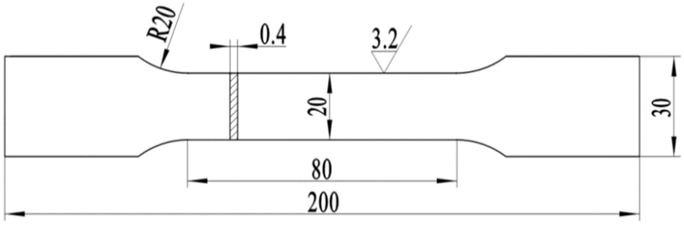
The material of U-shaped metal bellows is 316L austenitic stainless steel. The main chemical composition range of 316L austenitic stainless steel is shown in Table 1. The standard tensile specimen was cut along the axial direction of the tube blank, as shown in Figure 1. Then, the tensile test was carried out on the universal material testing machine (Inspekt table-100 kN). The sample preparation and test operation comply with EN ISO 6892-1-2019 tensile test standards for metallic materials.
2.2. SCTC Process
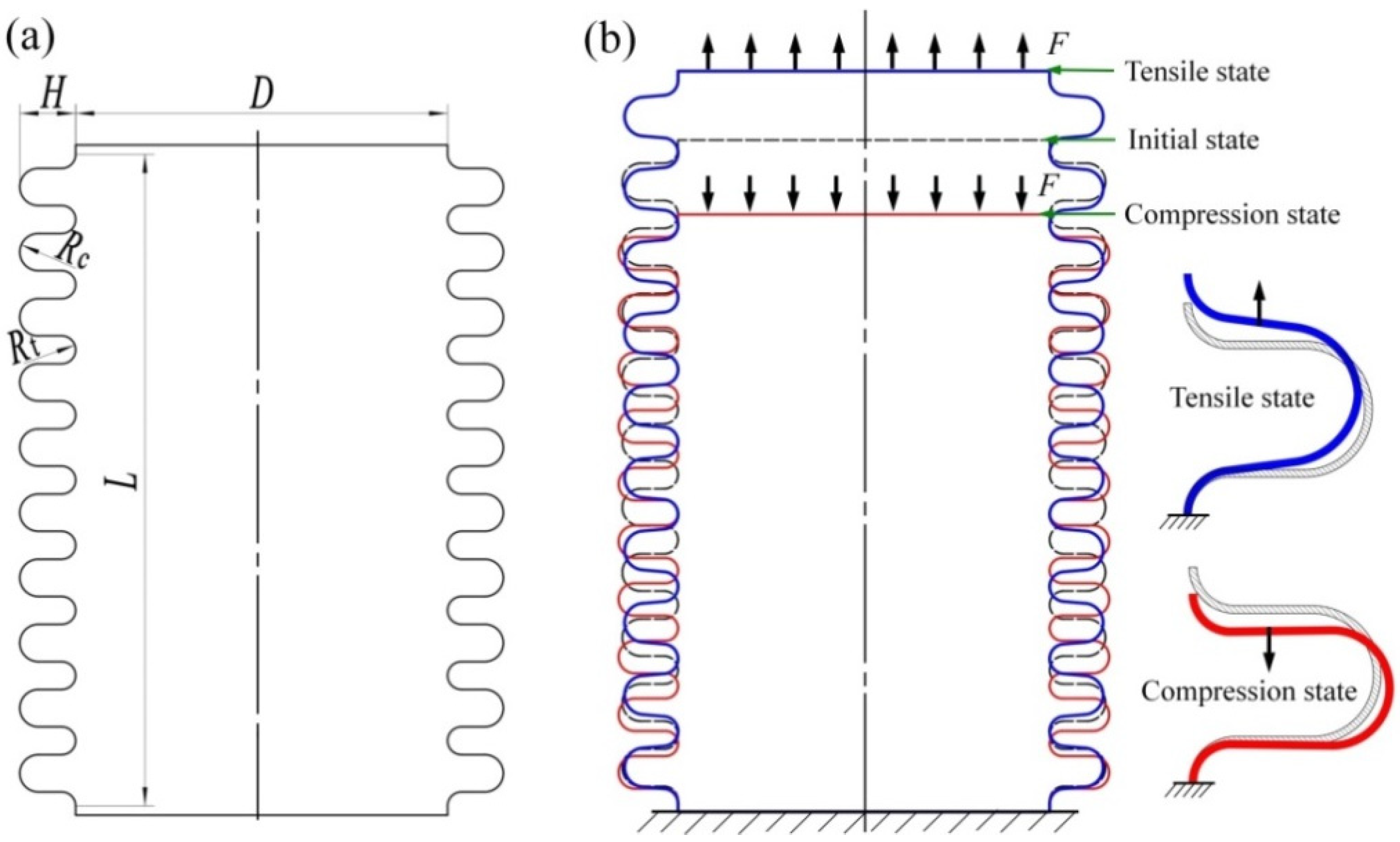
In engineering applications, the axial displacement generated by the pipeline is compensated and absorbed through the elongation and shortening deformation of the metal bellows, so as to ensure the stability of the pipeline system [26]. When the pipeline is elongated in the case of heat, the bellows at the connection end needs to undergo compression to absorb the displacement of the pipeline. However, the bellows need to be elongated to compensate for the displacement of the pipeline when the pipeline is shortened in the case of cold. The waveform structure parameters of metal bellows are shown in Table 2. The schematic diagram of the SCTC process of metal bellows is shown in Figure 2.
2.3. Finite Element Analysis
The axial SCTC process of metal bellows is numerically simulated by ABAQUS finite element software. The finite element model of metal bellows is established, as shown in Figure 3. The finite element model is divided into 15,676 elements using C3D8R elements. In order to improve the calculation efficiency and accuracy, according to the research results of the literature [27], the concentrated deformation area is divided into finer meshes. The elastic modulus is 205 GPa, the Poisson’s ratio is 0.3, the yield strength is 270 MPa, and the Mises yield criterion was selected. Metal bellows undergo tensile and compressive deformation under axial load.
2.4. SCTC Experiment
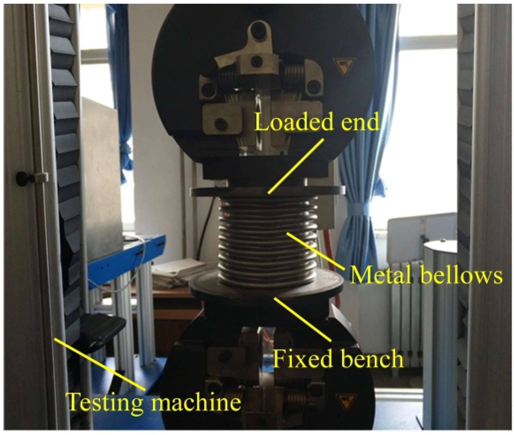
The SCTC experiment of metal bellows was performed by the universal material testing machine. The samples preparation and testing operation refer to the testing standard of GBT 33812-2017 for fatigue testing on metallic materials. The axial displacement amplitudes were ±6% L (±7.2 mm), ±8% L (±9.6 mm), ±10% L (±12.0 mm) and ±12% L (±14.4 mm), respectively. The testing speed was 20 mm/min. Thirty cycles were carried out, loading under each displacement amplitude, respectively. The experiment data of the load–displacement were then recorded and saved. The device used in the SCTC experiment is shown in Figure 4.
2.5. Analysis Methods
The samples of wave trough, sidewall area and wave crest of the waveform of the metal bellows were obtained by wire cutting. The hardness experiment was performed on the samples under SCTC stable deformation by a microhardness tester (VTD510P). A load of 9.8 N was used for 6 measurements in each sample, and the average value was taken for analysis.
The X-ray diffraction (XRD) peak of the samples in the wave trough of the metal bellows under the 30th SCTC loading was measured. The measurement was performed on a diffractometer with monochromatic Cu Kα radiation (D/MAX2500V).
In order to analyze the microstructure of the wave trough under repeated loading for 30 times under different displacement amplitudes, the prepared samples were polished and corroded with aqua regia solution. The corroded samples were observed by OM Zeiss optical microscope.
3. Results and Discussion
3.1. Material Properties
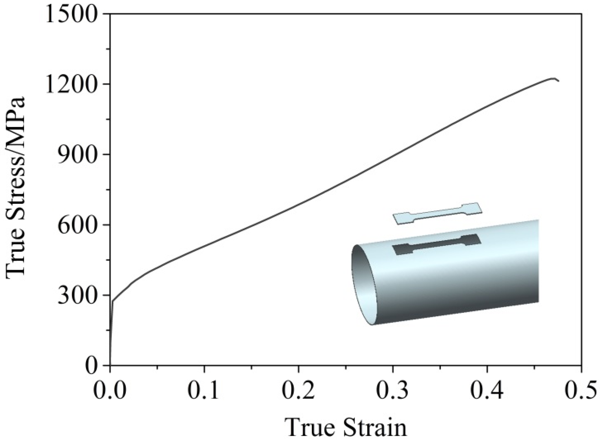
Figure 5 shows the stress–strain curve of 316L stainless steel. At room temperature, the deformation of the parallel section of the tensile specimen is uniform, and there is no obvious necking at the fracture, which indicates that the material has good plastic deformation ability. The elastic modulus of the material is 205 GPa, the Poisson’s ratio is 0.3, and the yield strength and tensile strength are 275 MPa and 1105 MPa, respectively.
3.2. Finite Element Simulation Results
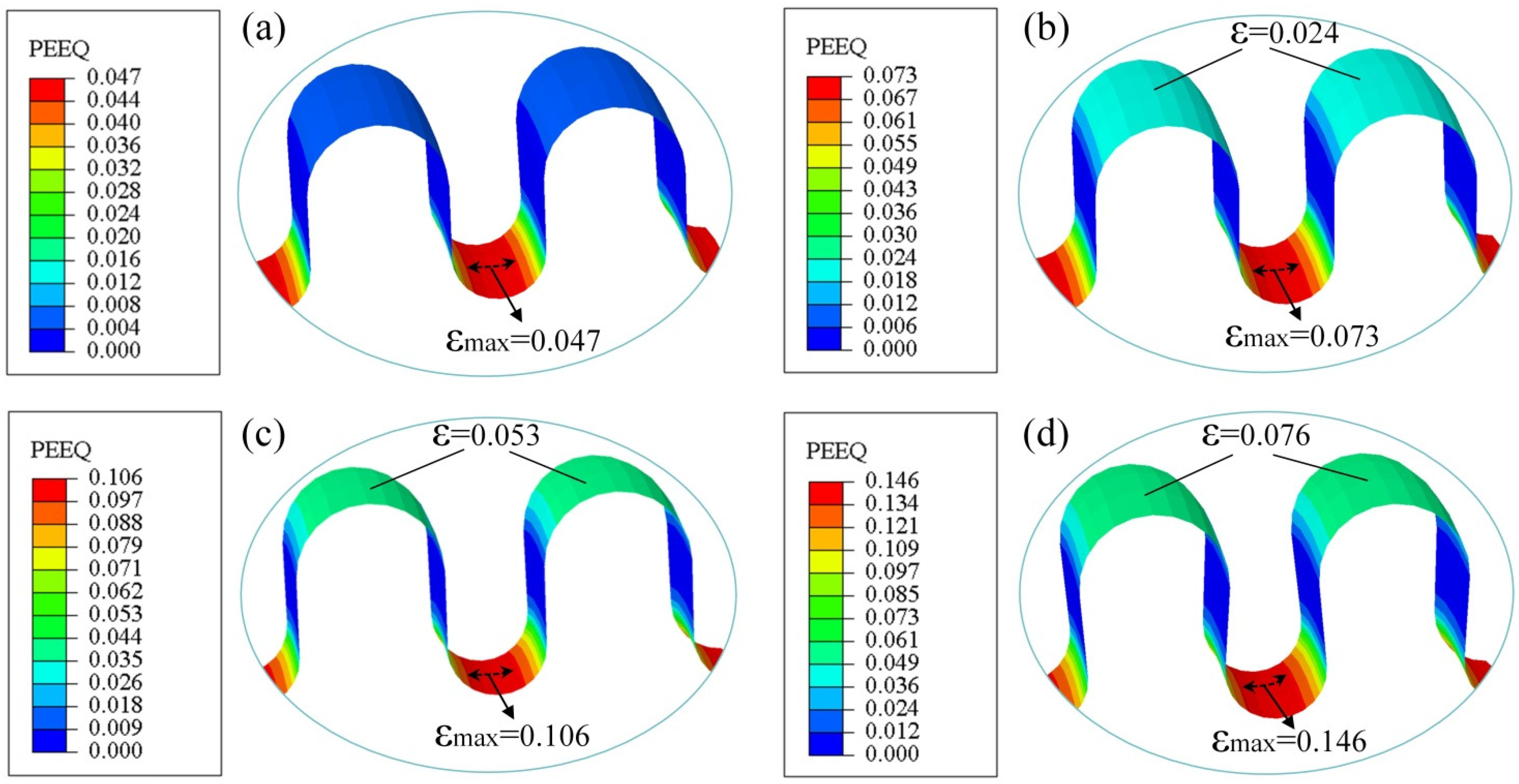
The equivalent plastic strain distribution nephogram of the metal bellows under the 30th SCTC loading is shown in Figure 6. The results show that the distribution law of equivalent plastic strain on each waveform of bellows is consistent under different loading displacement amplitudes. The equivalent plastic strain values are increased with the displacement amplitude, which is the largest in the wave trough. The maximum values of equivalent plastic strain under different amplitudes are 0.047, 0.073, 0.106 and 0.146, which were found under conditions of small strain and large deformation. This indicates that the wave trough area has undergone plastic deformation under SCTC loading, but the amount of deformation is small. Therefore, the waveform shape of the bellows does not change macroscopically after the SCTC loading.
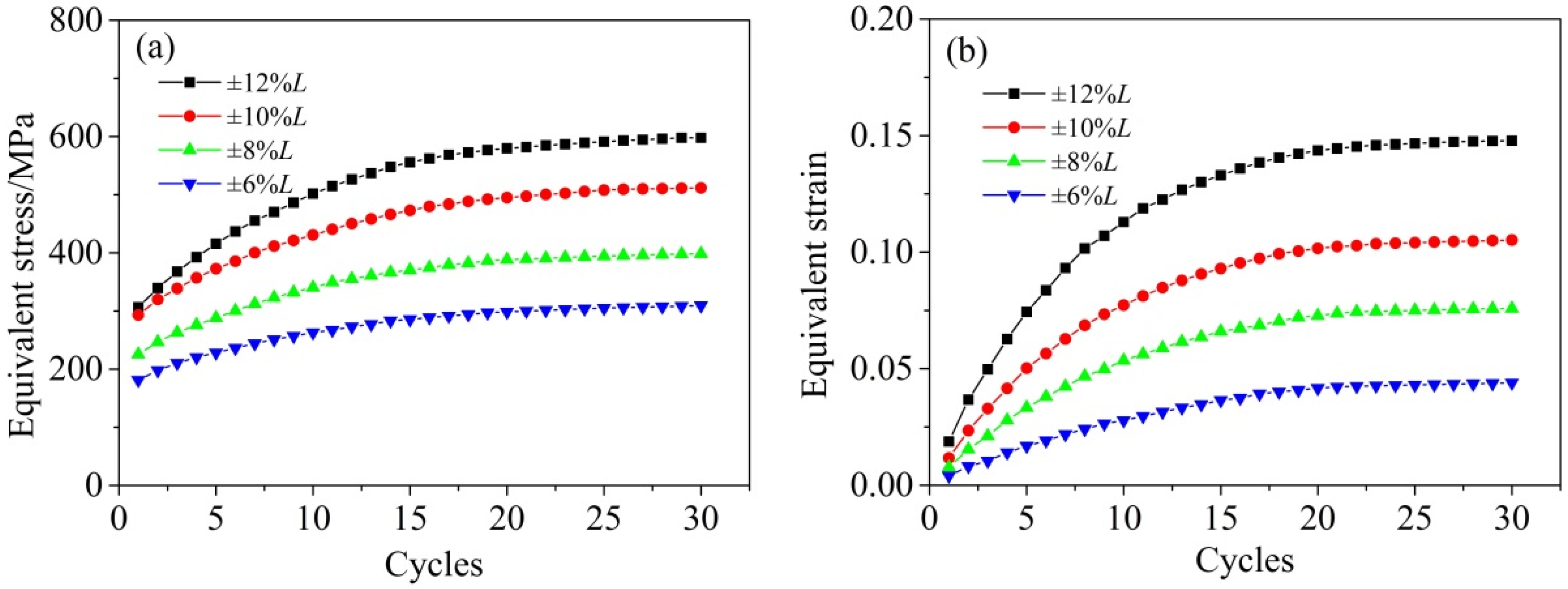
The distribution law of the maximum equivalent stress and strain values of the metal bellows with the cycles is shown in Figure 7. The values are increased with the amplitude of loading displacement. The maximum stress and strain values basically reach a saturated state after 20 cycles. This indicates that the plastic deformation in the concentrated deformation zone no longer accumulates after undergoing the 20th symmetrical repeated loading, and the plastic deformation of the material reached a stable state.
3.3. SCTC Experiment Results
3.3.1. Single Tension–Compression Loading Curve
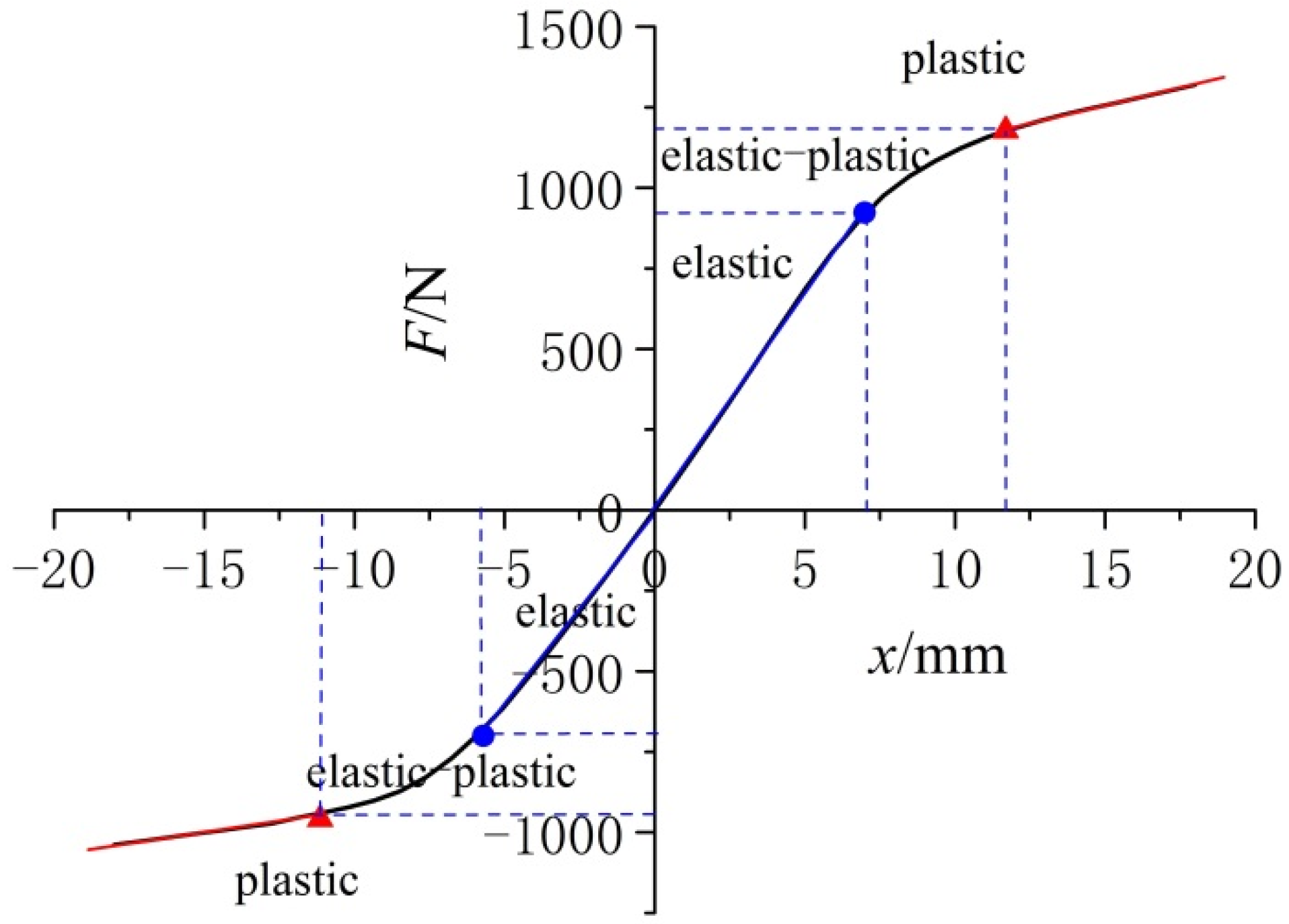
The distribution curve of the axial load with displacement of the metal bellows under single symmetrical tension and compression is shown in Figure 8. The axial load (F) and the displacement (x) have a linear relationship if the bellows are in the elastic deformation stage. The bending radius of the wave crest and wave trough fillet area is gradually enlarged (compressed). The metal bellows are elongated (shortened) in the axial direction. The maximum elastic displacement of the bellows in tension (compression) deformation is 6% L (−5% L), and the corresponding load value of F is 920 N (−715 N). After that, there is a nonlinear distribution between F and x, indicating that the wave trough and wave crest areas of the bellows have gradually entered the elastic–plastic deformation stage. When the axial displacement is increased to 10% L (−9.2% L) and the corresponding F is 1200 N (−980 N), the wave trough and crest areas mainly undergo plastic deformation. The results show that the plastic deformation zone no longer expands but continuously accumulates when the wave trough and wave crest zones entered the plastic strain hardening state. There is obvious asymmetry in single symmetrical tension and compression deformation due to the waveform structure.
The bellows will undergo elastic–plastic deformation when the axial displacement is large. This will make the metal bellows unstable at the initial stage of the SCTC loading, which affects the axial compensation performance and service life of the bellows. Therefore, it is necessary to further explore the stability of metal bellows in the stage of elastic–plastic deformation.
3.3.2. SCTC Curves
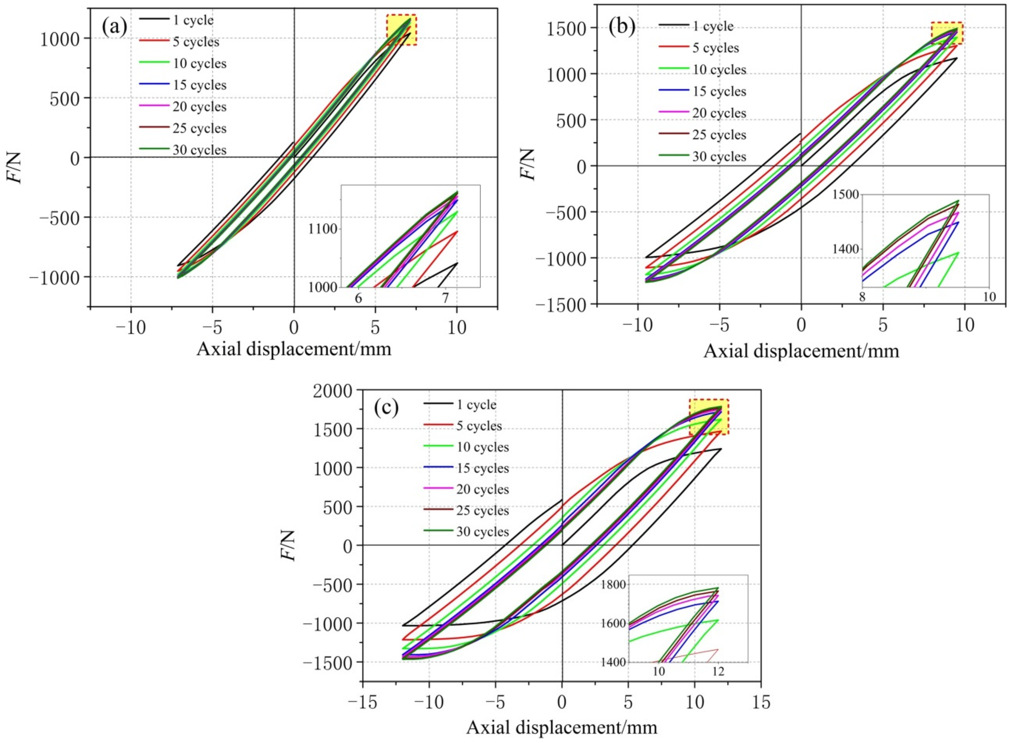
The load–displacement curve of metal bellows during the SCTC process is defined as a hysteresis loop. The hysteresis loop of metal bellows during the SCTC process is shown in Figure 9. The hysteresis loops under different displacement amplitudes basically coincided after the 20th cycle. This shows that the instability of metal bellows in the initial stage of tension–compression deformation will be eliminated. In addition, under the constant displacement amplitude, the width of the hysteresis loop decreases with the cycles, while the maximum axial load increases with cycles. After being subjected to 30 cycles of loading, the maximum axial tensile load values increased by 120 N, 312 N, and 531 N under the displacement amplitudes of ±6% L, ±8% L, and ±10% L, respectively, and the maximum axial compression load values increased by 110 N, 222 N, and 414 N, respectively. This indicates that the bellows have an obvious cyclic hardening phenomenon, but the hardening phenomenon is accompanied by the tension and compression asymmetry.
The distribution curves of the hysteresis loop width of metal bellows with cycles are shown in Figure 10. It can be seen from Figure 10 that under the same cycles, the width of the hysteresis loop increases with the constant displacement amplitude. After 20 symmetrical cycles of loading, the width of the hysteresis loop is basically stable. This means that the extension and compression compensation performance of the metal bellows gradually stabilizes with the increase in the symmetrical cycles. This is because the width of the plastic deformation zone of metal bellows is basically unchanged after multiple cycles of loading. If repeated loading continues, the plastic strain value only accumulates in the area that has entered the plastic deformation zone. At the same time, the material in the plastic deformation zone undergoes deformation hardening, and its strength improves, so the value of axial repeated loading gradually increases. The metal bellows will exhibit the stability characteristics of symmetrical cyclic loading when the plastic flow and hardening properties of metal materials in the concentrated deformation zone reach an equilibrium state.
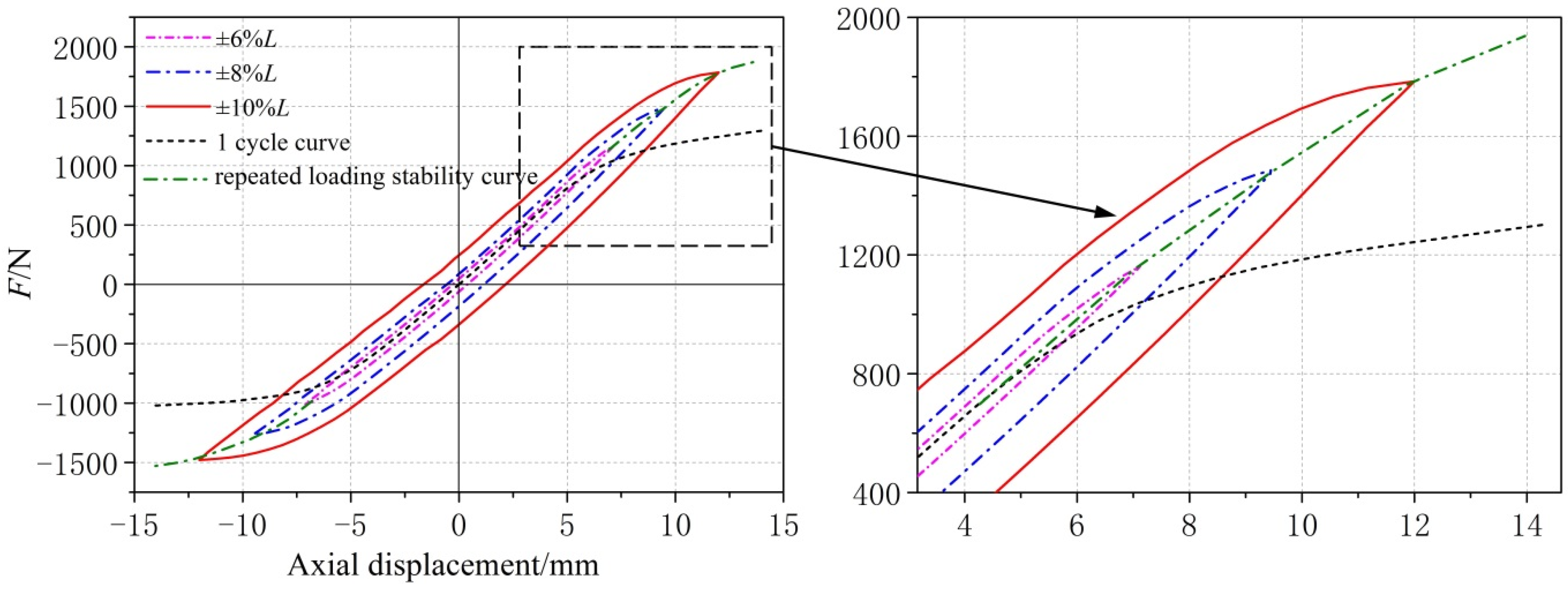
Figure 11 is a comparison diagram of the load–displacement curves, including different displacement amplitudes, of the single tension and compression process and the SCTC loading process. It can be seen from Figure 11 that the stable hysteresis loops under different displacement amplitudes are different. The vertices of each hysteresis loop are connected to obtain a stable load–displacement curve, and the load value is significantly higher than the load–displacement curve of the single tension and compression. The absolute value (150–240 N) of the maximum peak load is larger than that of the minimum peak load, showing asymmetric hardening characteristics. According to the stable load–displacement curve, the axial compensation performance of the metal bellows can be predicted more accurately. Furthermore, the elastic compensation of the metal bellows can be controlled to improve its service life.
3.3.3. Stability under SCTC Loading
In engineering application, the research on axial stiffness and axial yield load of the metal bellows after cyclic loading is stable will affect the prediction of the compensation performance and service life of the metal bellows.
Axial Stiffness
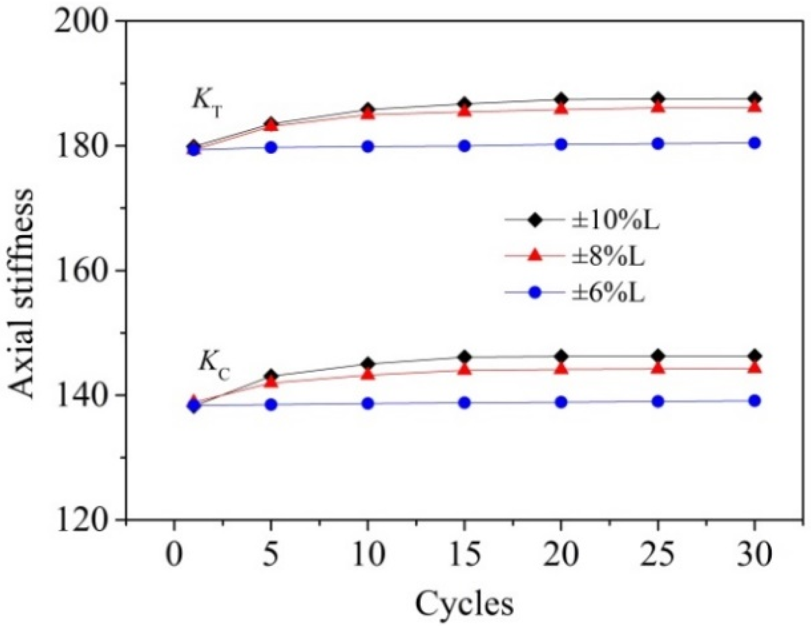
As the SCTC loading is a continuous loading process, it is assumed that the axial stiffness of tension loading is the same as that of compression unloading and that the axial stiffness of compression loading is the same as that of tension unloading. The elastic compression and tension unloading load–displacement curves of the hysteresis loop in Figure 9 were fitted. The distribution curves of the tensile axial stiffness (KT) and compression axial stiffness (KC) of the metal bellows with cycles were obtained, as shown in Figure 12.
It can be seen from Figure 12 that the axial stiffness values of tension and compression increased with cycles and displacement amplitude, respectively, in which the axial stiffness value of tension is large. After the 20th cycle, the axial stiffness was close to saturation. The axial tension stiffness and compression stiffness basically remained unchanged under the displacement amplitude of ±6% L; increased by 3.6% and 1.9%, respectively, under the displacement amplitude of ±8% L; and increased by 4.3% and 2.4%, respectively, under the displacement amplitude of ±10% L. This expresses that there is a deformation hardening phenomenon of metal bellows under SCTC loading, and the hardening phenomenon of tension process is relatively large. This is due to the unequal deformation of the fillet radius of the wave crest and trough of bellows during SCTC loading, resulting in the asymmetry of deformation hardening of the metal bellows.
Axial Yield Load
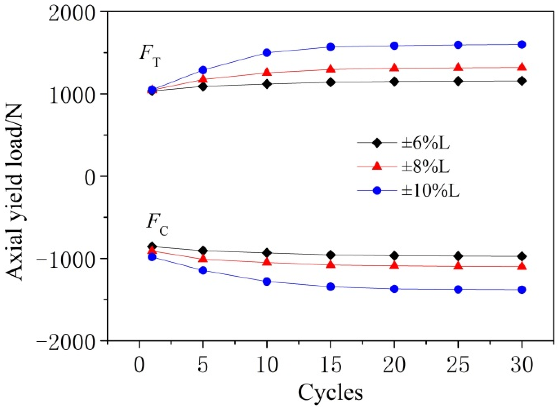
The hysteresis loop of the metal bellows has no obvious yield point, so the load value at 6% L of the deformation is defined as the axial yield load. The distribution curves of the axial yield load of metal bellows with cycles are shown in Figure 13. It can be seen from Figure 13 that the axial tensile yield load (FT) and compressive yield load (FC) values increase with the cycles, and their values are close to saturation after the 20th cycle. Under the displacement amplitudes of ±6% L, ±8% L and ±10% L, the axial tensile yield loads of the metal bellows increased by 11.9%, 26.3% and 52.4%, respectively, and the axial compressive yield loads increased by 13.9%, 21.1% and 40.5%, respectively. The FT and FC of the metal bellows increased obviously during the SCTC loading. Moreover, the larger the constant displacement amplitude of the bellows, the greater the increment of the corresponding yield load value, but there is a significant difference between the FT and FC, which makes the bellows show the asymmetry of tension and compression deformation. Therefore, this asymmetry should be noted during the analysis of the axial compensation performance of the bellows.
3.4. Hardness Measurement Results
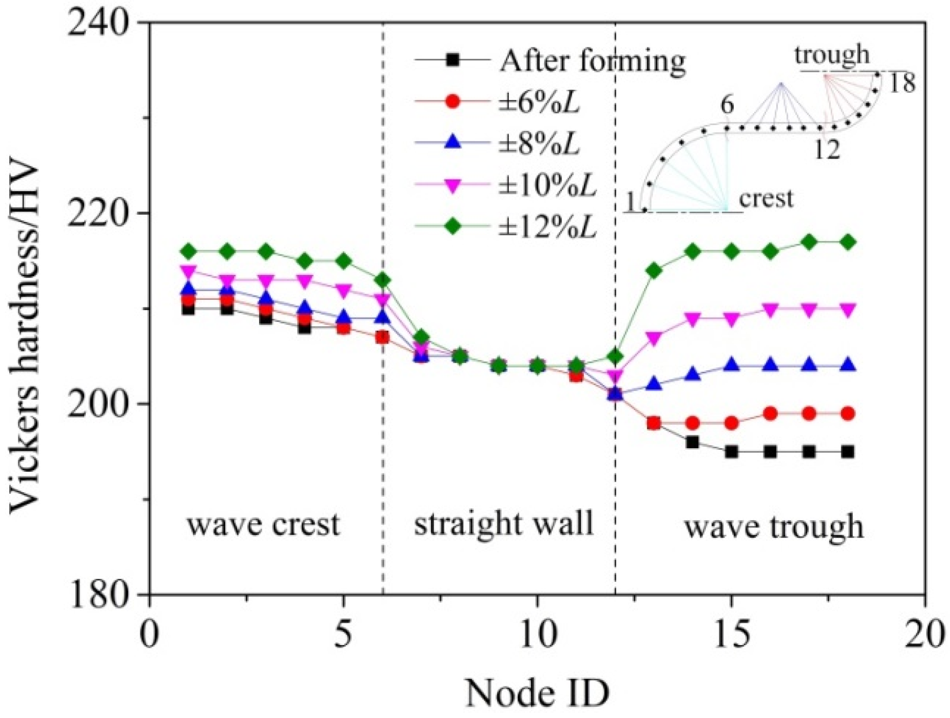
Due to the waveform of metal bellows being axisymmetric, the half waveform, including wave crest, sidewall and trough, was selected for hardness measurement. Figure 14 shows the hardness distribution curves of the waveform nodes under different displacement amplitudes after stable deformation. The research object of this paper is the hydraulic bulging bellows. It was confirmed by the literature [4] that plastic deformation occurred in the wave crest and side wall areas, but not in the wave trough area. Therefore, the hardness value of the wave crest area with severe plastic deformation is the largest. Comparing the hardness measurement results, the hardness values of the wave trough and wave crest are increased with the displacement amplitude, especially in the wave trough area. This is consistent with the maximum value of plastic strain in the wave trough area in the finite element analysis results. This is due to the serious work hardening of the material caused by the plastic deformation in the wave trough area, which leads to the maximum value of hardness measurement. Affected by the wave structure, the high strain in the wave trough area cannot be transferred to the surrounding low-strain area. Therefore, the hardening phenomenon in the wave trough area increases significantly with the cycles, and the metal materials reach the stability characteristics the earliest. As a result, the macroscopic mechanical properties of the bellows show stable characteristics.
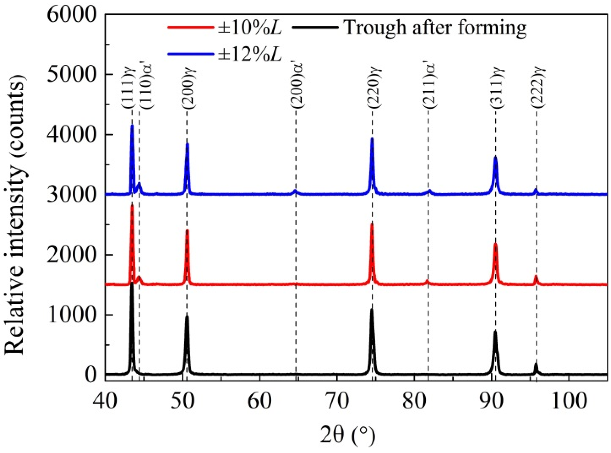
3.5. X-ray Diffraction
The XRD diffraction peak distribution curves of the metal bellows are shown in Figure 15. The peaks in the wave trough of the hydroforming metal bellows only refer to the austenite diffraction surface. The X-ray diffraction peaks of the sample in the wave trough area at a constant displacement amplitude of ±12% L confirmed that some austenite (γ) was transformed into martensite (α′). This is due to the plastic deformation that occurs in the trough area during repeated loading, which leads to deformation-induced martensite. There are more martensite diffraction peaks in the wave trough area of the metal bellows with the displacement amplitude. This indicates that the concentrated stress in the wave trough causes the plastic deformation to occur and accumulate continuously under different cyclic loading displacement amplitudes, resulting in deformation-induced martensite. As a result, the hardness value of the wave trough area of the metal bellows is increased, and the yield load value and repeated loading load value of the hysteresis loop are improved.
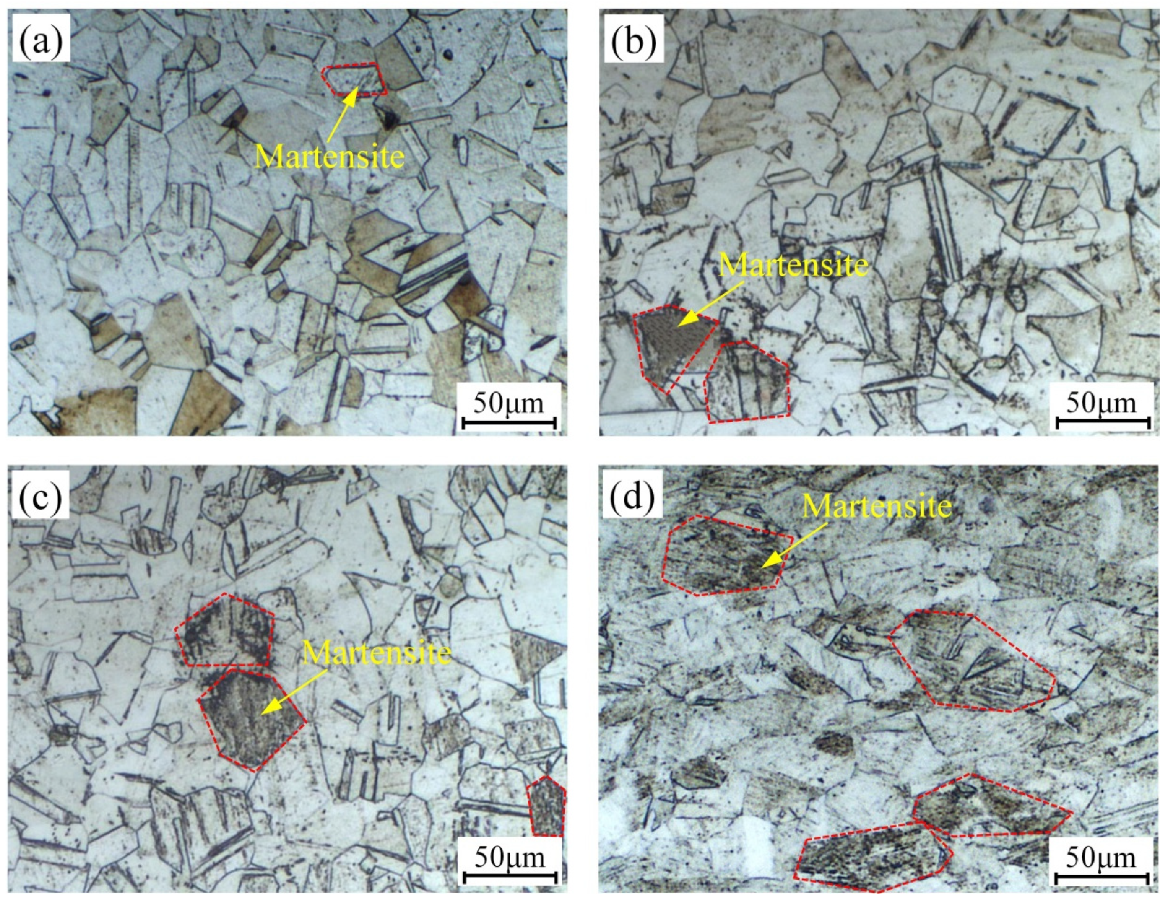
3.6. Microstructure
The microstructure of the wave trough of the metal bellows after 30 cycles of SCTC under different displacement amplitudes is shown in Figure 16. The matrix structure of 316L stainless steel is austenitic. According to the calibration results of the X-ray diffraction peak, a small number of typical features of the lath martensite microstructure were found in the wave trough area under ±10% L displacement amplitude, which is marked in the red line in Figure 16. The martensite structure in the grains in the wave trough area gradually increased with the displacement amplitude. Especially under the displacement amplitude of ±12% L, more martensite structure was produced inside the grains. The increase in martensite structure led to the hardness value of the deformation zone.
The concentrated stress in the wave trough area of the metal bellows under SCTC loading is large, and the slip system is opened inside the crystal grains, resulting in plastic deformation. As a result, a deformation-induced martensite structure is produced, and the yield strength of the metal material in the deformation zone is improved. When more slip systems are opened, more deformation-induced martensite will be generated, resulting in more grain boundary area to hinder the sliding of the slip band. The metal bellows present the stable characteristics of cyclic loading when the internal force of opening the slip band and the resistance at the grain boundary reach an equilibrium state.
4. Conclusions
In this paper, the low-cycle axial tension and compression experiments of metal bellows under the SCTC deformation process with a constant displacement amplitude were carried out. With the asymmetry and the stability mechanism of the metal bellows under SCTC loading revealed, the axial elastic compensation performance of metal bellows can be predicted and controlled to improve its service life. The main conclusions are as follows:
- (1)
- The amount of deformation distributed on each waveform of the bellows is uniform, and the deformation is mainly concentrated in the wave trough. After the 20th cycle of SCTC loading, the macroscopic mechanical properties of the metal bellows gradually stabilized.
- (2)
- The axial stiffness and yield load values of tension and compression were increased significantly during SCTC loading. The asymmetry of the metal bellows under the SCTC loading process was proved by the difference between the increased amounts.
- (3)
- The plastic deformation hardening at the wave trough is serious with the increase in displacement amplitude, resulting in a large hardness value. The deformation-induced martensite at the wave trough was confirmed by the X-ray diffraction peak. The microstructure of the wave trough reveals that the martensite inside the grains of the metal material increases the grain boundaries area. The metal bellows present stable characteristics under SCTC loading when the internal force of opening the slip band and the resistance at the grain boundary reach an equilibrium state.
Author Contributions
Conceptualization, Z.H.; Methodology, B.Y. and Z.H.; Software, B.Y.; Validation, Y.C.; Formal analysis, Y.C.; Writing—original draft preparation, B.Y. and Z.H.; Writing—review and editing, Z.H. and J.L.; Supervision, Z.H.; Funding acquisition, Z.H. All authors have read and agreed to the published version of the manuscript.
Funding
This project was supported by the North China Institute of Aerospace Engineering (305020243).
Institutional Review Board Statement
Not applicable.
Informed Consent Statement
Not applicable.
Data Availability Statement
Not applicable.
Conflicts of Interest
The authors declare no conflict of interest.
References
- Zhu, Y.Z.; Wang, H.F.; Sang, Z.F. The effect of environmental medium on fatigue life for u-shaped bellows expansion joints. Int. J. Fatigue 2006, 28, 28–32. [Google Scholar] [CrossRef]
- Expansion Joints Manufacturing Association (EJMA). 1996. Available online: http://www.ejma.org/ejma-standards/ (accessed on 30 November 2021).
- Ye, H.; Qian, J.; Yan, S.; Jiang, C.; Jin, Z. Ultimate bending moment for pipes with two circumferential flaws under combined internal pressure and bending. Int. J. Mech. Sci. 2016, 106, 319–330. [Google Scholar] [CrossRef]
- Hao, Z.L.; Xi, C.Y.; Huang, Z.H.; Luo, J.T. Hydraulic bulging process with axial feedings and strain field of U-shaped metal bellows. J. Cent. South Univ. 2018, 25, 2712–2721. [Google Scholar] [CrossRef]
- Yuan, Z.; Huo, S.H.; Ren, J.T. Mathematical description and mechanical characteristics of reinforced S-shaped bellows. Int. J. Pers. Ves. Pip. 2019, 175, 103931. [Google Scholar] [CrossRef]
- Krovvidi, S.; Goyal, S.; Bhaduri, A. Design and analysis of formed bellows for nuclear applications—Case study. Procedia Struct. Integr. 2019, 14, 855–863. [Google Scholar] [CrossRef]
- Zhang, W.W.; Cong, S. Failure analysis of SUS304 sheet during hydro-bulging based on GTN ductile damage model. Int. J. Adv. Manuf. Technol. 2015, 86, 427–435. [Google Scholar] [CrossRef]
- Steinheimer, R.; Engel, B. Thermal Influences during Rotary Draw Bending of Tubes from Stainless Steel. Procedia Eng. 2014, 81, 2165–2170. [Google Scholar] [CrossRef] [Green Version]
- Daxin, E.; Li, R. Influence of additional tensile force on the stress and deformation of numerically controlled tube bending. Int. J. Adv. Manuf. Technol. 2015, 78, 895–905. [Google Scholar] [CrossRef]
- Yu, G.C.; Ma, R.; Zhai, R.X.; Zhao, J. Mechanical properties in cyclic tension-compression loading process on sheet metal. Procedia Manuf. 2018, 15, 1769–1776. [Google Scholar] [CrossRef]
- Yu, G.C.; Zhao, J. Evolution of Mechanical Properties in Cyclic Tension-compression Loading on Sheet Metal. Chin. J. Mech. Eng. 2019, 55, 33. [Google Scholar] [CrossRef]
- Huang, X.Y.; Yu, G.C.; Sun, H.L.; Zhao, J. A mechanical model of axial and circumferential bidirectional deformation for large thin-walled pipes in the process of continuous and synchronous calibration of roundness and straightness by three rollers. Int. J. Adv. Manuf. Technol. 2021, 16, 3809–3826. [Google Scholar] [CrossRef]
- Huang, X.Y.; Zhao, J.; Yu, G.C.; Meng, Q.D.; Mu, Z.K.; Zhai, R.X. Three-roller continuous setting round process for longitudinally submerged arc welding pipes. T. Nonferr. Metal. Soc. 2021, 31, 1411–1426. [Google Scholar] [CrossRef]
- Hao, Z.L.; Luo, S.Y.; Zhao, H.; Luo, J.T. Effect of Plate Hardening Behavior on the Deformation of Stainless Steel Metal Bellows. J. Mater. Eng. Perform. 2017, 26, 5385–5395. [Google Scholar] [CrossRef]
- Christopher, J.; Choudhary, B.K. On the assessment of tensile work hardening behaviour of type 316L(N) austenitic stainless steel in the framework of θσ d, vs. σ d, using flow stress contribution from dislocations. Int. J. Pres. Ves. Pip. 2016, 146, 151–160. [Google Scholar] [CrossRef]
- Silvestre, E.; Mendiguren, J.; Galdos, L. Comparison of the hardening behaviour of different steel families: From mild and stainless steel to advanced high strength steels. Int. J. Mech. Sci. 2015, 102, 10–20. [Google Scholar] [CrossRef]
- Pierce, S.O.; Evans, J.L. Failure analysis of a metal bellows flexible hose subjected to multiple pressure cycles. Eng. Fail. Anal. 2012, 22, 11–20. [Google Scholar] [CrossRef]
- Qin, X.; Gao, D.L. The effect of residual bending on coiled tubing buckling behavior in a horizontal well. J. Nat. Gas Sci. Eng. 2016, 30, 182–194. [Google Scholar] [CrossRef]
- Huo, S.H.; Yan, W.Z.; Xu, X.J.; Yuan, Z. Bending characteristics of the reinforced S-shaped bellows under internal pressure—ScienceDirect. Int. J. Pers. Ves. Pip. 2021, 192, 104412. [Google Scholar] [CrossRef]
- Xiang, X.M.; Lu, G.; Li, Z.X. Finite element analysis and experimental study on a bellows joint. Eng. Struct. 2017, 151, 584–598. [Google Scholar] [CrossRef]
- Silva, M.; Fragoso, H.; Barrio, R. Stress corrosion of an austenitic stainless steel expansion joint, a case study. Eng. Fail. Anal. 2019, 97, 300–310. [Google Scholar] [CrossRef]
- Pavithra, E.; Kumar, V. Experimental Investigation and Numerical Analysis on Fatigue Life of Bellows. Mater. Today 2018, 5, 18848–18856. [Google Scholar] [CrossRef]
- Panda, B.; Sujata, M.; Madan, M. Stress corrosion cracking in 316L stainless steel bellows of a pressure safety valve. Eng. Fail. Anal. 2014, 36, 379–389. [Google Scholar] [CrossRef] [Green Version]
- Hao, Z.L.; Luo, J.T.; Jin, Y.B. Failure Analysis of Corrugated Metal Hose under Ultimate Repeated Bending Process. Eng. Fail. Anal. 2019, 109, 104295. [Google Scholar] [CrossRef]
- Hao, Z.L.; Luo, J.T.; Chen, L.H.; Chen, Y.H.; Cai, Y. Failure Mechanism of Unequal Parameters Metal Bellows under Repeated Bending Process. Eng. Fail. Anal. 2021, 129, 105671. [Google Scholar] [CrossRef]
- Liu, C.; Lu, K.; Sheng, L.; Song, Y. Manufacture and test of seismic bellows for ITER magnet feeder. Fusion Eng. Des. 2016, 109, 515–520. [Google Scholar] [CrossRef]
- Saad, D.; Dundulis, G.; Janulionis, R. Calculation of SIFs for semi-elliptical surface cracks in U-shaped bellows expansion joints of Es-Salam research reactor vessel. Eng. Fail. Anal. 2020, 111, 104481. [Google Scholar] [CrossRef]
Figure 1.
Schematic of the tensile specimen.

Figure 2.
The schematic diagram of the SCTC process of metal bellows: (a) metal bellows model; (b) SCTC process.
Figure 2.
The schematic diagram of the SCTC process of metal bellows: (a) metal bellows model; (b) SCTC process.

Figure 3.
The finite element model of metal bellows: (a) boundary conditions; (b) meshed model.

Figure 4.
The SCTC experiment device.

Figure 5.
Mechanical properties of 316L stainless steel.

Figure 6.
The equivalent plastic strain distribution nephogram of the metal bellows under the 30th SCTC loading: (a) ±6% L; (b) ±8% L; (c) ±10% L; (d) ±12% L.
Figure 6.
The equivalent plastic strain distribution nephogram of the metal bellows under the 30th SCTC loading: (a) ±6% L; (b) ±8% L; (c) ±10% L; (d) ±12% L.

Figure 7.
The distribution law of the maximum equivalent stress and strain values of the wave trough node with cycles: (a) equivalent stress; (b) equivalent strain.
Figure 7.
The distribution law of the maximum equivalent stress and strain values of the wave trough node with cycles: (a) equivalent stress; (b) equivalent strain.

Figure 8.
The distribution curve of the axial load with displacement of the metal bellows under single symmetrical tension and compression.
Figure 8.
The distribution curve of the axial load with displacement of the metal bellows under single symmetrical tension and compression.

Figure 9.
The hysteresis loop of metal bellows during the SCTC process: (a) ±6% L; (b) ±8% L; (c) ±10% L.
Figure 9.
The hysteresis loop of metal bellows during the SCTC process: (a) ±6% L; (b) ±8% L; (c) ±10% L.

Figure 10.
The distribution curves of the hysteresis loop width of metal bellows with cycles.

Figure 11.
The comparison diagram of load–displacement curves.

Figure 12.
The distribution curves of the KT and KC of the metal bellows with cycles.

Figure 13.
The distribution curves of axial yield load of metal bellows with cycles.

Figure 14.
The hardness distribution curves of the waveform nodes under different displacement amplitudes after stable deformation.
Figure 14.
The hardness distribution curves of the waveform nodes under different displacement amplitudes after stable deformation.

Figure 15.
The XRD diffraction peak distribution curves of the metal bellows.

Figure 16.
The microstructure of the wave trough of the metal bellows after 30 cycles of SCTC under different displacement amplitudes: (a) ±6% L; (b) ±8% L; (c) ±10% L; (d) ±12% L.
Figure 16.
The microstructure of the wave trough of the metal bellows after 30 cycles of SCTC under different displacement amplitudes: (a) ±6% L; (b) ±8% L; (c) ±10% L; (d) ±12% L.


Table 1.
Main chemical compositions of the 316L austenitic stainless steel.
| Element | C | Si | Mn | P | S | Cr | Ni | Mo |
|---|---|---|---|---|---|---|---|---|
| percentage/wt.% | 0.03 | 0.75 | 2.0 | 0.045 | 0.03 | 16.0~18.0 | 10.0~14.0 | 2.0~3.0 |
Table 2.
Waveform structure parameters of metal bellows.
| Parameters | D | t | H | Rc | Rt | n |
|---|---|---|---|---|---|---|
| Size/mm | 80 | 0.4 | 10 | 3.6 | 2.4 | 10 |
where D is the nominal diameter of the bellows; L is the effective length; t is the wall thickness; n is the wave number; and H, Rc, Rt are the wave height, the wave crest fillet radius, and the wave trough fillet radius of the metal bellows, respectively.
Publisher’s Note: MDPI stays neutral with regard to jurisdictional claims in published maps and institutional affiliations. |
© 2021 by the authors. Licensee MDPI, Basel, Switzerland. This article is an open access article distributed under the terms and conditions of the Creative Commons Attribution (CC BY) license (https://creativecommons.org/licenses/by/4.0/).
Share and Cite
MDPI and ACS Style
Hao, Z.; Yao, B.; Chen, Y.; Luo, J. Stability Characteristics and Mechanism of U-Shaped Metal Bellows under Symmetrical Cyclic Tension and Compression Process. Symmetry 2021, 13, 2451. https://0-doi-org.brum.beds.ac.uk/10.3390/sym13122451
AMA Style
Hao Z, Yao B, Chen Y, Luo J. Stability Characteristics and Mechanism of U-Shaped Metal Bellows under Symmetrical Cyclic Tension and Compression Process. Symmetry. 2021; 13(12):2451. https://0-doi-org.brum.beds.ac.uk/10.3390/sym13122451
Chicago/Turabian StyleHao, Zengliang, Biao Yao, Yuhang Chen, and Junting Luo. 2021. "Stability Characteristics and Mechanism of U-Shaped Metal Bellows under Symmetrical Cyclic Tension and Compression Process" Symmetry 13, no. 12: 2451. https://0-doi-org.brum.beds.ac.uk/10.3390/sym13122451
Note that from the first issue of 2016, this journal uses article numbers instead of page numbers. See further details here.