Review

Continuous-Flow Photocatalytic Microfluidic-Reactor for the Treatment of Aqueous Contaminants, Simplicity, and Complexity: A Mini-Review

1
School of Chemical, Biological, and Environmental Engineering, Oregon State University, Corvallis, OR 97331, USA
2
Department of Chemical Engineering, Gyeongsang National University, 501 Jinju-daero, Jinju-si 52828, Korea
*
Author to whom correspondence should be addressed.
Submission received: 1 April 2021 / Revised: 1 July 2021 / Accepted: 5 July 2021 / Published: 23 July 2021
(This article belongs to the Special Issue Symmetry and Complexity of Catalysis in Flow Chemistry)

Abstract

:
Water pollution is a growing global issue; there are many approaches to treating wastewater, including chemical coagulation, physical adsorption, and chemical oxidation. The photocatalysis process has provided a solution for removing pollutants from wastewater, where the pair of the photoelectron and hole works through an asymmetric way to degrade the contaminants under UV irradiation. This method offers an alternative route for treating the pollutant with a lower energy cost, high efficiency, and fewer byproducts. A continuous-flow microfluidic reactor has a channel size from tens to thousands of micrometers, providing uniform irradiation and short diffusion length. It can enhance the conversion efficiency of photocatalysis due to the simple spatial symmetry inside the microreactor channel and among the individual channels. In addition, the bandgap of TiO2, ZnO, or other photocatalyst nanoparticles with symmetric crystal structure can be modified through doping or embedding. In this mini-review, a review of the reported continuous-flow photocatalytic microfluidic reactor is discussed from the perspective of both microreactor design and material engineering.

1. Introduction

Water is an essential natural resource for the whole of earth’s ecosystem, covering more than 70% of the earth’s surface. High-level pollutants in wastewater from in-creased human activities must be separated or made harmless before discharge into streams or before reuse. Heavy metals such as lead (Pb), mercury (Hg), cadmium (Cd), copper (Cu), and arsenic (As) can cause severe health damage to both aquatic organisms and humans. Many toxic herbicides and pesticides that are listed as known carcinogens are released to the soil and water bodies during agriculture activities. Organic pollutants from paper, textile, or other industries have long been of concern due to their long-term persistence in the natural water system, leading to critical environmental hazards. For example, harmful and toxic organic dyes and their metabolites have been posing severe threats to humans due to their effects on the liver, kidney and cardiovascular system [1]. Mercury can accumulate in fish, and mercury-contaminated fish can cause neurological dysfunction in humans [2]. Japan decided to release nuclear wastewater into the Pacific Ocean from the Fukushima Daichi Nuclear Power Plant on 13 April 2021, which can cause a long-term impact on the environment [3]. Pathogenic bacteria in the contaminated water can also cause various diseases, such as diarrhea and gastrointestinal illness [4]. Many existing approaches can treat the wastewater to reduce the contamination. For example, methods have been developed to remove the dyes in water, including chemical coagulation, physical adsorption, and chemical oxidation using ozone or H2O2 [5]. However, the coagulated or adsorbed dyes are only transferred from one phase to another and can still act as a pollution source. In contrast, chemical oxidation involves toxic oxidants and consumes excessive energy. The photocatalysis process provides an alternative solution to remove the contaminants in the wastewater with benefits of a lower energy cost, high efficiency in destroying the organic dyes, and less byproduct waste. Studies have shown that photocatalysis can be adopted to eliminate all types of water contamination, including the degradation of organic dyes [6,7,8], removal of metals [2,9,10], degradation of antibiotics [11,12,13], removal of radioactive materials [14,15,16], and the inactivation of bacteria [17,18]. In some typical photocatalytic wastewater treatments, the organic dyes are eliminated by employing semiconductor materials such as TiO2 and ZnO under UV irradiation [19]. In particular, as a compound semiconductor with a direct bandgap of 3.37 eV, ZnO has been widely studied due to its good photocatalytic performance and ease of synthesis [20,21,22]. The conventional suspension-based photocatalytic reactor is not efficient from the reactor design perspective because photocatalytic colloidal nanoparticles readily aggregate in the suspension system. The light intensity varies upon the location of the reactor. The photocatalyst has been integrated into a microreactor system to address these issues. The microfluidic-based photocatalytic reactor, with some inherent advantages of the microreactor system, such as the high surface-to-volume ratio, short diffusion distances, and rapid mass transfer, has improved the photocatalytic performance degrading organic contaminants [23,24].
There are three main objectives for this review paper: (1) providing insights into some basic working principles of microfluidic-based photocatalysis, (2) highlighting innovation in photocatalytic microreactor design, fabrication, and catalyst material engineering; and (3) identifying future directions. Understanding reactor and catalyst design principles can help researchers develop more efficient microfluidic-based photocatalytic reactors to treat aqueous contaminants.

2. Mechanism of the Photocatalysis

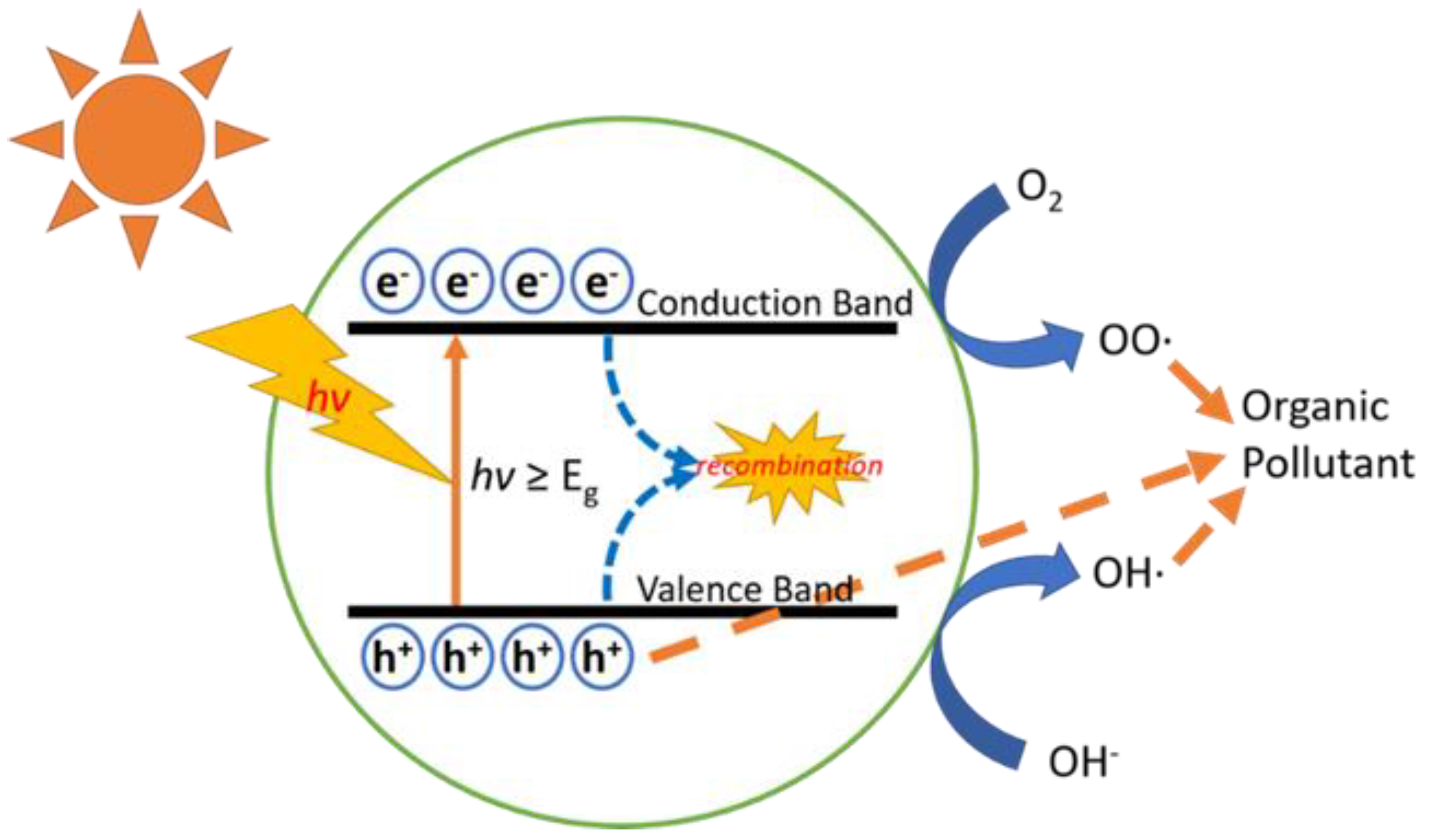
2.1. Redox-Based Heterogeneous Photocatalysis

Most microfluidics and suspension systems that degrade organic compounds are based on the same mechanism. In a typical photocatalysis process (Figure 1), as the photocatalytic materials absorb the light with sufficient energy, electrons in the valence band are excited to the conduction band while leaving holes in the valence band. ZnO is used as a typical photocatalyst example (Equation (1)) [25]. These electrons in the conduction band ( e C B ) and holes in the valence band ( h V B + ) either undergo recombination and release heat (Equation (2)) or react with water and dissolved oxygen (O2) in the aqueous medium. The holes in the valence band can react with the water to produce the hydroxyl radicals (Equation (3)). The holes in the valence band can also directly convert the organic pollutant to intermediate compounds, which are highly reactive and thus lead to the subsequent oxidation process (Equation (4)). In the conduction band, the electrons can react with O2 molecules to form superoxide radicals (Equation (5)) and further form the hydroperoxyl radicals (Equation (6)). All these resultant radicals are strong oxidants that play a crucial role in degrading organic pollutants, followed by subsequent mineralization at the end (Equations (7) and (8)).
ZnO h ν ZnO ( e C B + h V B + )
e C B + h V B + h e a t
h V B + + H 2 O   OH + H +
h V B + + organic   pollutant degraded   products
e C B + O 2   OO
OO + H +   OOH
OH + organic   pollutant degraded   products
OOH + organic   pollutant degraded   products
The following reaction is an example of the degradation of formaldehyde (HCHO), a common organic small-molecule pollutant:
HCHO + OH HCO + H 2 O
HCO + OH HCOOH
HCOOH + 2 h V B + CO 2 + 2 H +

2.2. Photo-Assisted Fenton Reaction

The Fenton reaction is a homogenous oxidation process, which H. J. Fenton first described [26]. Iron (II) (Fe2+) is used as a catalyst to enhance the oxidative potential of H2O2. The original Fenton process can be described as the following reactions [27]:
Fe 2 + + H 2 O 2 Fe 3 + + OH + OH
OH + H 2 O 2   OOH + H 2 O
Fe 2 + + OH Fe 3 + + OH
Fe 3 + + OOH Fe 2 + + O 2 + H +
OH + OH H 2 O 2
OH + organic   pollutant degraded   products
The Fe3+ to Fe2+ reaction (Equation (15)) is slow, and once all Fe2+ ions are oxidated to Fe3+, the reaction does not proceed. UV irradiation can regenerate the Fe2+ by photo-reduction of Fe3+ (Equations (18) and (19)). Meanwhile, H2O2 also photolyzes with UV light and generates more radicals for pollution degradation (Equation (20)).
Fe 3 + + H 2 O + h ν Fe 2 + + OH + H +
Fe 3 + + H 2 O 2 + h ν Fe 2 + + OOH + H +
H 2 O 2 + h ν 2   OH

2.3. Microbe-Photocatalyst Hybrids

A microbe-photocatalyst hybrids (MPH) system is a combination of microbial cells with photocatalyst coating on the surface. The photoelectron generated from the photocatalyst can be transported to the microorganism for enzyme-catalyzed reactions [28], meanwhile the hole can still degrade the organic pollutant in the water.
Microbial sedimentation has been used to settle the dissolved heavy metal ions [29]. The deposited nanomaterials on the microorganisms’ surfaces can work as the photocatalyst and form the MPH system with microorganisms. Zuo et al. proposed a comprehensive strategy for heavy metal treatment by MPH: using dissolved heavy metal ions to synthesize the photocatalyst, reducing the heavy metal ions that are toxic in high valence states such as Cr6+ and Se4+, and using heavy metal ions that are toxic in low valence states as the sacrificial electron donors [30].

3. Kinetics of Microfluidics Photocatalysis

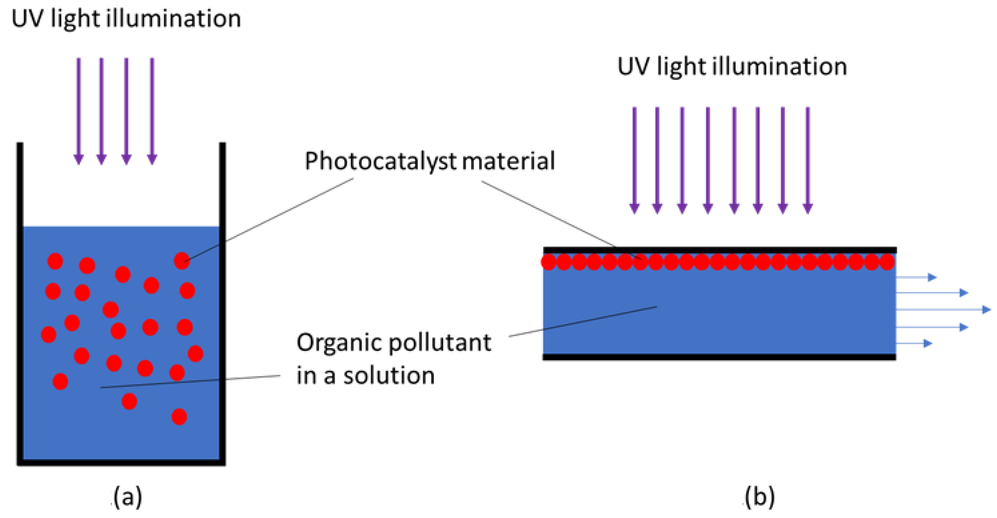
3.1. Comparison of Microfluidics with a Suspension System in Photocatalytic Activity

In conventional wastewater treatment, light illuminates the suspension composed of photocatalyst nanoparticles (NPs) and pollutants under vigorous stirring, as shown in Figure 2a [31]. This suspension-based system inherently imposes a large gradient in temperature, acidity, and concentration over spatial position and reaction time. Additionally, the photocatalyst NPs should be removed after the reaction, which is a formidable process and requires excessive energy and time.
Immobilized photocatalytic materials on the internal surface of the microreactor can overcome these problems, and the organic pollutant solution is subject to flow inside the microreactor [32]. A microfluidic reactor, with a channel size within the sub-millimeter level, can provide uniform irradiation of light and short diffusion length for highly efficient photocatalytic performances [33]. As shown in a typical microfluidic-based photocatalysis process in Figure 2b, a solution stream containing the target organic compounds flows through the microchannel, where the photocatalyst is immobilized on the surface of the channel. When UV light illuminates the whole channel, a strong oxidant such as a hydroxyl radical generated by the photocatalyst reacts with organic dyes to decompose them [34,35,36]. Compared with the suspension system, the microfluidic-based process has several advantages that can enhance the photocatalytic performance: (1) The pollutants can contact the photocatalytic materials more efficiently due to the short diffusion distance. (2) The surface area of the photocatalytic materials can be increased by reasonably designing the microreactor geometry. (3) The degradation of the organic pollutants can be kinetically tailored by the flow rate of the solution and reactor dimension, which eventually leads to the optimal process conditions to degrade the organic pollutants best. (4) Lastly, a remarkable feature of the microfluidic-based system is the reuse of photocatalytic materials without an additional recovery process.

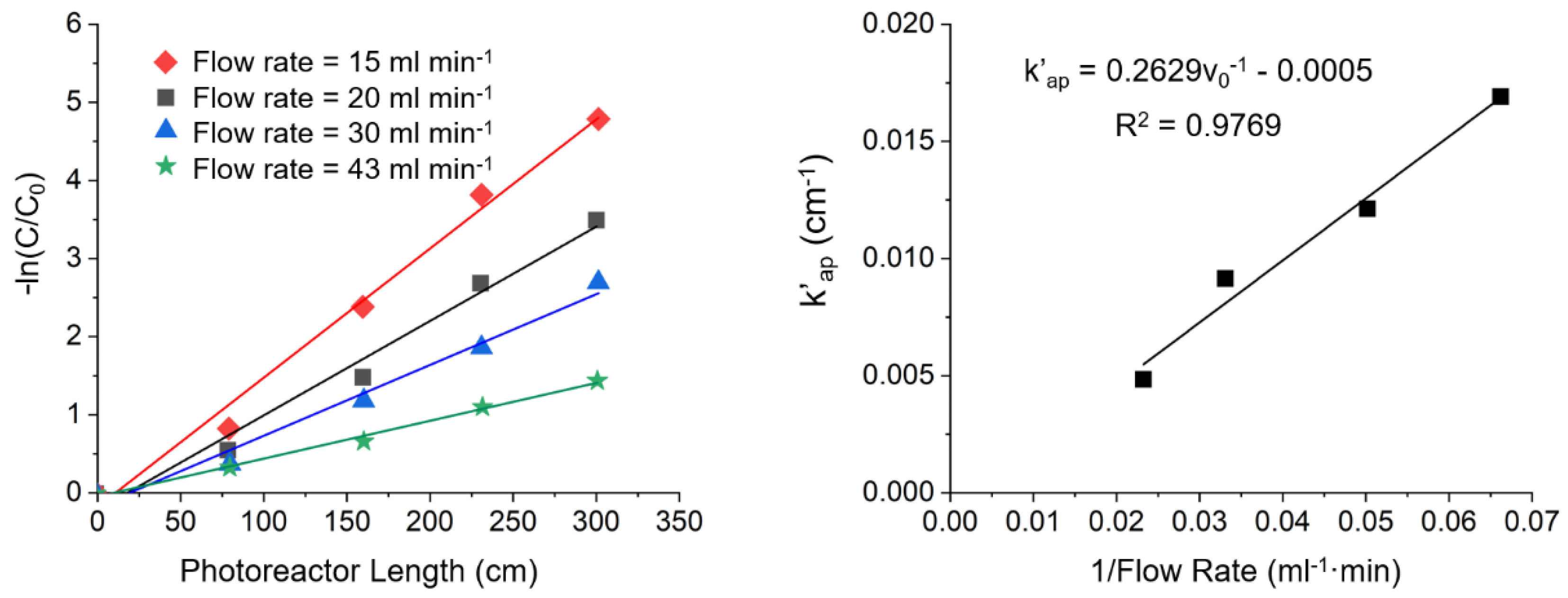
3.2. Photocatalytic Reaction Kinetic Study of Organic Compound Degradation in a Microfluidic System

To evaluate the performance of the photocatalyst, one direct method is to use the percentage of degradation [37]:
degradation   % = ( 1 C t C 0 ) × 100 %
where Ct is the measured concentration of the pollutant after degradation for a certain time t, C0 is the original concentration of the pollutants before the degradation. A higher degradation percentage means less pollutants remain, and the efficiency of the device is higher.
Many factors can influence the performance of the photocatalyst, including the temperature, light source, pollutant concentration, and for the photocatalytic process in a microfluidic reactor, the operation condition also plays an important role, such as the flow rate of the device, the area of the photocatalyst, and the cycle of the flow.
Herein, some of the results from the literature are presented to give a general idea of the efficiency of a photocatalytic microfluidic reactor. Meng et al. studied photocatalytic microreactor efficiency using nanofibrous TiO2, and found that the degradation percentage of the nanofibrous TiO2 was about 20% at the first cycle, and increased to about 60% after 10 cycles [38]. Roselin et al. used ZnO for photocatalytic degradation of Reactive Red 22 in a flow reactor, and the degradation percentage reached about 98.3% in 6 cycles [39]. In Moussavi’s study, the reduction percentage of Cr(VI) can reach 100% in less than 10 min [40].
In a microfluidic reactor, the flow rate can influence the degradation of the pollutants. To exclude the transport effect of the reactor, a kinetic study is performed to better understand the performance of a photocatalytic device.
In a microfluidic-based photocatalytic process, the organic pollutant compound molecules’ transport to the photocatalytic materials and their subsequent adsorption on these photocatalytic materials play an essential role in determining the degradation rate of the organic molecules. Some computational and empirical studies have been carried out to elucidate the reaction kinetics of the degradation in this context.
Behnajady et al. experimentally studied the photocatalytic degradation of an azo dye (AR27) in a continuous flow photoreactor. Based on the experimental results, they suggested a kinetic degradation model by using the Langmuir–Hinshelwood mechanism [37]. The kinetics of photocatalysis in a suspension system follows a pseudo-first-order reaction Equation (22).
r = d C d t = k obs C
where r, kobs, and C are the reaction rate, observed rate constant, and the organic compound’s concentration, respectively. Note that the observed rate constant is a function of competitive adsorption of intermediates on the photocatalyst surface.
The microfluidic device, modeled as a plug flow reactor, assumes a homogenous fluid mixing in the radial and angular direction. The mass balance equation of the plug flow reactor at the steady-state can be expressed as follows:
d C d V D = r Q
where Q and VD are the flow rate of the solution and the reactor’s volume, respectively. Substituting Equation (22) into Equation (23) gives:
d C d V D = k obs C Q
Solving Equation (24) obtains:
ln C outlet C inlet = V D k obs Q = S k obs Q l = k obs l
k obs = S k obs Q
Coutlet and Cinlet are the concentration of azo dye leaving and entering the microfluidic device, respectively; S is the reactor’s cross-section area, and l is the channel length and k obs is the observed reaction rate constant as a function of channel length and flow rate.
The photodegradation rate was estimated under different channel flow rates and lengths by applying the kinetics study. The results indicate that with the decrease of the flow rate, the degradation rate increased. The linear relation indicates the pseudo-first-order reaction kinetics, as shown in Figure 3.
Corbel et al. studied the mass transfer rate and relevant modeling in a microchannel photocatalytic reactor [41]. Degradation of salicylic acid (S.A.) was conducted in two microreactors with different depths. The experimental results in Figure 4a show that the conversion yield of S.A. in the microreactor with a depth of 0.5 mm (R1) is higher than the reactor with a depth of 0.75 mm (R2) due to the lower limitation by mass transfer in reactor R1. To further study the kinetics of degradation, two kinetics models were studied: a kinetics model (sim. L.H.), which is based on the Langmuir–Hinshelwood kinetic equation, suggests the removal rate of S.A. is governed by the balance between the flux of S.A. to the photocatalytic materials and the photodegradation reaction. On the other hand, the different models (sim. transf.) only consider mass transport from the bulk to the photocatalytic materials. The comparison results of the two models are shown in Figure 4b, indicating that the mass transport model agrees with the experiments. With the mass transport model and conversion yield data, the external mass transfer constant was also estimated.

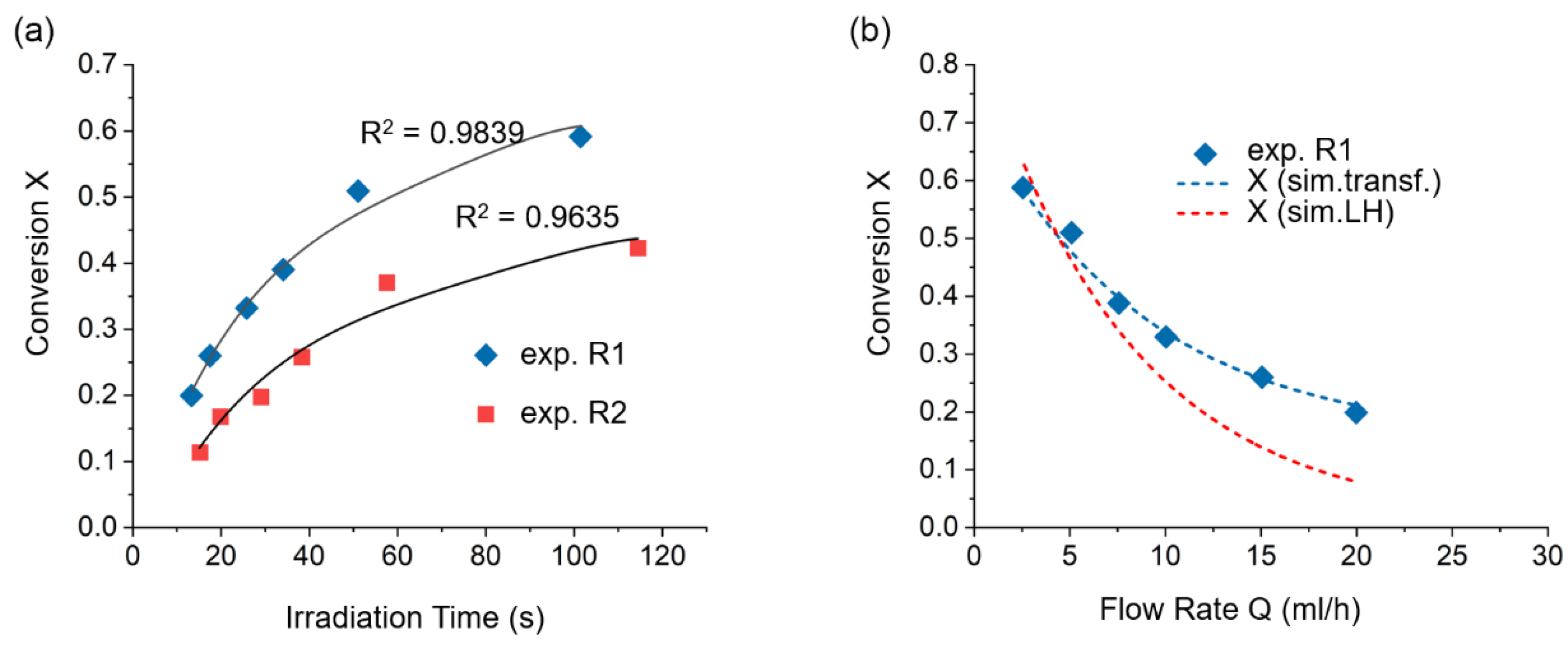
3.3. Comparison between the Batch Reactor and Microfluidic Reactor

A comparison has been made between the macroscopic reactor and the microfluidic reactor. Mendoza et al. studied the transition from conventional batch to microfluidic process for the photooxygenation of methionine and enhanced the initial rate of photooxygenation and space-time yield using a continuous flow reactor [42]. In addition, their study also showed that both mass transfer limitations and light penetration play essential roles in the process.
Zhan et al. provided a study on the kinetics model of immobilized photocatalyst in batch reactor and microfluidic reactor to compare the kinetics between batch reactor and continuous flow reactor [43]. The Langmuir–Hinshelwood (LH) mechanism was used to describe the heterogeneous photocatalytic reactions, and the intrinsic reaction rate can be expressed as:
r int = k int m cat K LH C 1 + K LH C
where mcat is the catalyst mass, KLH is the adsorption equilibrium constant of the reactant, C is the mass concentration of the pollutant in the liquid phase, and kint is the intrinsic reaction rate constant.
In a bath reactor, the observed pollutants consumption rate can be expressed as:
R obs = V batch d C b d t
where Vbatch is the volume of the batch reactor, and d C b d t is the observed change of the pollutant concentration in the bulk solution with time. In a bath reactor, the liquid concentration C is equal to the pollutant concentration in the bulk Cb, the change of the pollutant concentration can be expressed as:
d C b d t = 1 V batch k int m cat K L H C b 1 + K L H C b
On the other hand, in a microfluidic reactor, the observed pollutants consumption rate can be expressed as:
d C b d z = 1 V ˙ L MR R obs
where V ˙ is the flow rate of the solution in the microreactor, and LMR is the length of the microreactor. Due to the convection of the solution, the concentration of the pollutant in the bulk solution Cb is different from the photocatalyst surface CS. A mass balance between the diffusive flux to the catalyst surface and the rate of consumption on the catalyst surface is established to solve the Equations (27) and (30):
β m ( C b C S ) = 1 A cat k int m cat K LH C S 1 + K LH C S
where the βm is the mass transfer coefficient, and Acat is the external surface area of the catalyst layer.

4. Design and Fabrication of the Microfluidic Reactor

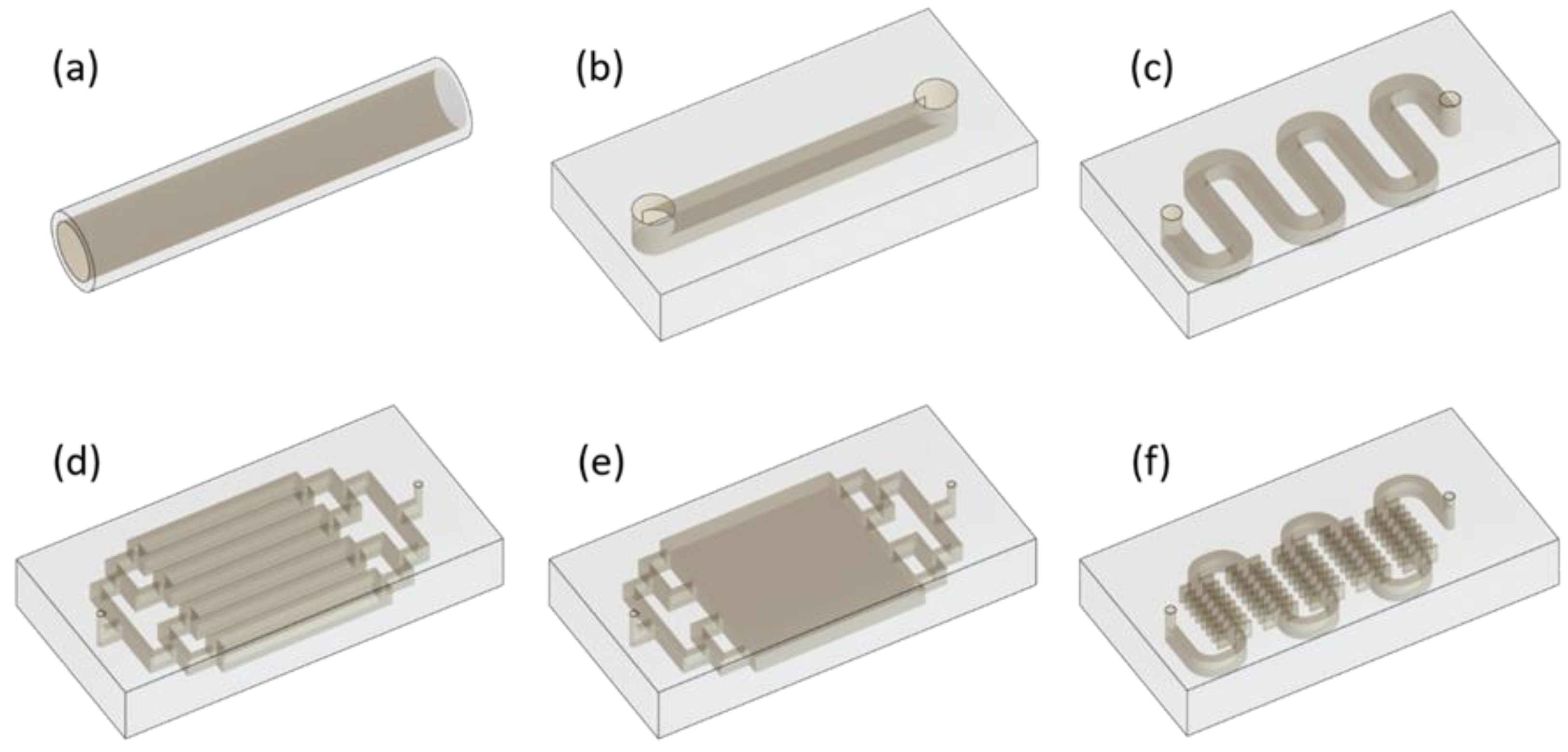
4.1. Geometric Design of the Microfluidic Photocatalysis Reactor

Various design concepts have been introduced to fabricate the microfluidic photocatalytic device to enhance the target compounds’ conversion. Microreactors with different geometries have been reported to increase efficiency and study the kinetics of photocatalysis under continuous flow conditions. One convenient approach is to load a micro-capillary tube with photocatalysts on its inner walls, as illustrated in Figure 5a. The degradation of the target pollutant occurs on the inner walls’ surface when the solution flows through the microchannels [24]. Another way is to fabricate the photocatalyst on a glass substrate, and the solution containing the pollutant flows through the surface guided by a channel. The simplest one is a line channel, as illustrated in Figure 5b [44]. Polyline channels [45] and parallel line channels [46] have also been employed to use more surface area of the substrate, as shown in Figure 5c,d. These approaches increase the contacting area between the solution and photocatalytic surface; thus, enhancing the photocatalytic conversion can be expected. A planar channel with pillar arrays on the substrate was fabricated to increase the contacting area further, as illustrated in Figure 5e [47]. Figure 5f shows that it is possible to increase the surface area of the loaded catalyst by introducing a side lobe structure on the channel [48].
Visan et al. developed a single-channel microreactor embedding the immobilized photocatalytic materials to study the intrinsic degradation kinetics of cortisone 21-acetate (C.A.) [45]. The reactor performance was evaluated, using a single channel microreactor, shown in Figure 6a, by first-order reaction rate with either light independence or light dependency described by a photon-absorption carrier generation mechanism. This modeling can lead to a rational reactor design and easy optimization. Castedo et al. fabricated multiple parallel channels for the photocatalytic generation of hydrogen simply and efficiently using 3D printing and PDMS polymerization, shown in Figure 6b [46]. The Au/TiO2 photocatalyst was immobilized on the silicon microchannel wall, and the performance of the microreactor was tested under different water-ethanol gaseous mixtures. Han et al. designed a planar chamber with a large area and high-density ZnO nanowires to achieve high photocatalytic efficiency for degradation of methylene blue, shown in Figure 6c [49].

4.2. The Light Source for the Photocatalysis

The majority of the reports used TiO2 and ZnO as a photocatalyst. As a result of the bandgap values of TiO2 and ZnO, a UV light source is commonly used to enable the electrons to move from the valence band to the conduction band. A doped TiO2 or ZnO can lower the bandgap value, which allows photocatalysis under visible light. Another approach introduces a lower bandgap material and creates a heterojunction with TiO2 or ZnO to broaden the light spectrum’s utilization. Wang et al. described a microfluidic reactor that uses a BiVO4/TiO2 heterojunction photocatalyst [50]. BiVO4 can absorb visible light, and TiO2 can absorb near UV light. They used a Xe lamp as a light source to simulate sunlight. Using BiVO4 on indium tin oxide (ITO) coated glass, the same group also described microfluidic photo-electrocatalytic reactors with an integrated visible-light source [51].
In a typical microfluidic photocatalytic device, the light source is placed outside the reactor. Inevitably, part of the incident light can be reflected and absorbed by the window of a microreactor, resulting in a loss of photons and energy waste. Some studies have sought out to mitigate this issue. For example, a light source was inserted into a tubular reactor so that the light can directly shine on the solution and the photocatalyst [52]. A rotating disk or tube photocatalytic reactor, shown in Figure 7, can be used where a thin liquid film carried by a rotating disk or tube is directly exposed to the UV light [53].

5. Photocatalytic Materials Engineering

ZnO and TiO2 are the most commonly used metal oxide materials for photocatalysis. However, several factors limit the performances of the photocatalytic reaction. For example, the charge carrier recombination can limit the number of available electron-hole pairs for the reaction, which leads to the reduced efficiency of the degradation. Another limitation is related to the charge separation dependency on the energy of the incident light. To improve the performance of the photocatalyst, therefore, dopants or composite photocatalyst design has been employed. Here, we exemplify ZnO photocatalysts to demonstrate how the photocatalytic performance can be improved by modifying the pristine ZnO material. As mentioned previously, the efficiency of the photocatalyst is governed by the photo-induced electron-hole pairs. The photocatalysis process for the dye degradation can only proceed when the incident light has greater energy than the ZnO materials’ bandgap. In this way, only UV light with a wavelength less than 387 nm can be utilized for the photocatalysis process. ZnO has three different crystal structures: hexagonal wurtzite, cubic zincblende and rocksalt. The hexagonal wurtzite is the most thermodynamically stable structure under room temperature, where four O2− anions surround each Zn2+ cation at the corners of a tetrahedron and vice versa [55]. Doping appropriate materials into the ZnO crystal can narrow the bandgap and inhibit the recombination of the photo-induced electrons and holes, leading to enhanced photocatalytic performance under the visible light region [56]. Doping with metal ions can narrow the ZnO bandgap, resulting in a shift of the absorption edge to the visible range. Many metal ion dopants have been studied, including copper, cadmium, tin, cobalt, aluminum, and iron [57,58,59,60,61,62]. Mohan et al. found that doping with copper can cause surface defects, which can serve as favorable trap sites of the electrons or holes to reduce their recombination and enhance the performance [63]. Ba-Abbad et al. incorporated iron ions (Fe3+) into ZnO via the sol-gel technique [64]. The results indicated longer wavelength absorption in the visible light range and a redshift of the bandgap. Furthermore, Karunakaran et al. studied the performance of cadmium doped ZnO; they concluded that the doping would not change much of the bandgap structure but reducing the grain size of the ZnO structure would destroy the microstructure [65].
In doping with a non-metal atom, the oxygen atoms are substituted by non-metal atoms, which will shift the valence band energy of ZnO upward and narrow its bandgap energy. Carbon (C), nitrogen (N), and sulfur (S) are promising candidates among non-metal atoms [56,66]. Yu et al. incorporated N into the ZnO crystals to form the N 2p states in the bandgap, which improves the visible light absorption and enhancement of the photocatalytic activity [56]. The incorporated N atoms can exist in the ZnO lattice’s interstitial sites; the doped N can improve the visible light absorption and photocatalytic activity [67]. C-doped ZnO also showed an enhanced visible light absorption up to 700 nm [68].
Coupling ZnO crystals with guest materials, such as Ag, Bi2O3, ZnS, MoS2, and TiO2 to form a composite material can also improve photocatalytic activity [69,70,71,72]. In the composite material, ZnO is directly contacted with guest materials. The coupled materials have two different energy levels. Upon irradiation, the photo-induced electrons can be transferred from ZnO to the guest materials, which inhibits the recombination of the electron-hole pairs [34]. Ag is a promising metal to couple with ZnO to form the composite photocatalyst and has been studied extensively. The coupled Ag-ZnO material mainly plays two roles. The first is to reduce the hole-electron recombination due to the Schottky barrier at the metal-semiconductor interface [73]. The Ag’s other function is to enhance the visible light absorption of the composite system induced by Ag’s surface plasmonic absorption [74]. Similar strategies have been applied to improve the performance of the other metal oxide semiconductors, such as TiO2, by changing the material’s bandgap and preventing recombination of the holes and electrons. For example, nitrogen is doped into TiO2 crystals for visible light photocatalysis [75,76]. Metal atoms, such as silver [77], copper [78], aluminum [79], and iron [80] have also been studied to enhance the photocatalytic performance of TiO2 material.
Several strategies have been used to immobilize the photocatalyst on the substrate surface. The simplest one is to directly deposit a thin film on the substrate, as illustrated by Figure 8a [45]. The thin films can adopt different structures, such as a thick film with porous structures or a nanostructured thin film. However, the thin film’s active surface area is limited, which can hinder the performance of photocatalysis. Structures with a higher loading amount and higher active surface area have been fabricated to increase the contact between the solution and the photocatalyst. For example, in Figure 8b, the TiO2 nanoparticles were coated on fiberglass to enlarge the reaction area and enhance the degradation efficiency [81]. Figure 8c shows that the TiO2 nanoparticles were coated onto the SiO2 beads with high mechanical stability and surface area [82]. The function of the SiO2 is to provide a supporter surface to load the catalyst. On the other hand, a composite structure, such as a Pt-coated ZnO nanorods array, shown in Figure 8d, was constructed to enhance photocatalytic efficiency by effectively separating the photo-induced electron-hole pairs [24].
Besides these traditional metal oxide photocatalysts, novel photocatalyst materials have been developed and introduced to reduce the contaminants in wastewater. Plasmonic photocatalysts have gained great attention owing to their enhanced efficiency under visible light. Different metal nanoparticles, such as gold [83], silver [84], and aluminum have been studied as the plasmonic photocatalyst and have shown great efficiency in the visible light region. A plasmonic photocatalyst contains the contact between a metal and a semiconductor, forming the Schottky junction that inhibits the electron-hole recombination [85]. One feature of the plasmonic photocatalyst is the localized surface plasmon resonance (LSPR) effect of the nanostructured noble metal, which is a strong oscillation of the free electrons stimulated by the incident light, resulting in enhanced light absorption and scattering [86].
Other novel photocatalytic materials, such as BiSbO4 [87], Nd2Sn2O7 [88,89], (BiO)2CO3 [90,91,92,93,94], La2Ti2O7 [95], PrVO4 [96], and ZnTiO3 [97] have also been studied for degradation of the water contaminant.
In addition, some earth abundant, non-metal photocatalysts have been reported. For example, red phosphorus was prepared by a mechanical ball milling method and showed the enhanced photocatalytic performance under visible light [98]. Graphite-like carbon nitride (g-C3N4) is another metal-free, n-type semiconductor that can be used in photocatalysis due to its promising properties, such as unique electric, optical, structural and physiochemical properties [99,100,101].

6. Examples

The larger surface area of the microchannel is typically pursued to enhance the photocatalytic activities. In this regard, attempts have been made to increase the surface area of the microchannel. Lindstrom et al. designed a microfluidic reactor encompassing 11 parallel microchannels with 32 side lobes per channel, leading to a significant increase in the surface area (Figure 9) [48]. With such a high surface area, the authors enabled an extremely high loading factor of 66 g anatase TiO2 per liter of methylene blue solution. Azzouz et al. increased the surface area of the microfluidic reactor by fabricating a multi-hierarchical micro-nano structure [47]. In particular, ZnO nanowires were subsequently grown on the micro-nano structure fabricated by deep reactive ion etching of silicon (Figure 10). Contaminated water containing benzene, toluene, ethylbenzene, m- p- xylenes, and o-xylene flowed through the microreactor for purification. The photocatalytic results demonstrated high photocatalytic efficiency, with degradation of the contaminated water up to 95% within 5s.
In addition to the design concept of adjusting channel shapes and surface area, a novel photocatalytic reactor, called a rotating disk photocatalytic reactor (RDPR), was reported [53]. In this type of reactor, a thin film of liquid containing the target compound is carried into the catalyst surface by a semicircular part of a rotating disk coated with TiO2, as shown in Figure 7a. The photocatalytic reaction to remove the chlorinated phenols and pesticides occurs in the thin-film liquid under UV irradiation before the thin film rotates back to the vessel. A similar design concept was employed to achieve scale-up of the photocatalytic system. The multiple rotating tubes are equipped to carry the numerous liquid films simultaneously (Figure 7b) for the degradation of azo dye [54]. Like the single RDPR reactor, the thin film of liquid formed on the tube surface is exposed to UV radiation for the photocatalytic reaction.
Aran et al. demonstrated a new membrane microreactor concept for multiphase photocatalytic reactions (Figure 11) [102]. In this concept, the microfluidic channel was fabricated on a porous α-Al2O3 substrate, and the TiO2 photocatalyst was immobilized on the channel walls. The porous α-Al2O3 allows the supply of the gas to the channel, and its hydrophobic property can prevent the water from leaking, enabling a stable gas-liquid-solid system. The result has shown that the membrane-assisted supply of O2 enhanced the photocatalytic degradation of phenol and methylene blue.

7. Summary and Future Perspective

In this review, different research aspects of microfluidic-based photocatalysis have been presented, including studying the reaction kinetics, design of the microreactor to enhance the performance, and the engineering of the catalyst efficiency. The previous studies have already proven that the photocatalytic microfluidic reactor has excellent potential to remove organic contaminants in water by taking advantage of its high efficiency, catalyst reusability, and continuous operation. Despite these advantages, many areas require further investigation before its real-world application.
  • The majority of the reported photocatalytic microfluidic reactors use UV light sources. Typical UV lights have low energy efficiency. It will improve sustainability if one can replace the UV lights with sunlight. More studies in this area are needed.
  • Not many studies are devoted to optimizing the utilization efficiency of photons at the reactor level. More studies in optimum photocatalytic reactor design that consider both optics and catalytic reactions are needed.
  • The majority of the reported photocatalytic microfluidic reactors remain lab-scale and are not suited for large-scale deployment. More studies on scalable photocatalytic microreactors, including microstructured reactor design, are needed.
  • Fundamental research to enlighten the photocatalytic reaction kinetics using scalable microfluidic devices in the labs is another area that will support the development of more efficient photocatalytic microreactors.

Author Contributions

Conceptualization: C.-H.C. (Chih-Hung Chang); writing original draft: Z.G., C.P.; review and editing: C.-H.C. (Chang-Ho Choi), C.-H.C. (Chih-Hung Chang). All authors have read and agreed to the published version of the manuscript.

Funding

This work was supported by the National Science Foundation, USA, grants CBET-1449383 NNCI-2025489, National Research Foundation of Korea (NRF) (No. 2019R1I1A3A01058865) and Walmart Manufacturing Innovation Foundation (29955421).

Institutional Review Board Statement

Not applicable.

Informed Consent Statement

Not applicable.

Data Availability Statement

Not applicable.

Conflicts of Interest

The authors declare no conflict of interest.

References

  1. Shanker, U.; Rani, M.; Jassal, V. Degradation of hazardous organic dyes in water by nanomaterials. Environ. Chem. Lett. 2017, 15, 623–642. [Google Scholar] [CrossRef]
  2. Byrne, H.E.; Mazyck, D.W. Removal of trace level aqueous mercury by adsorption and photocatalysis on silica–titania composites. J. Hazard. Mater. 2009, 170, 915–919. [Google Scholar] [CrossRef]
  3. Lu, Y.; Yuan, J.; Du, D.; Sun, B.; Yi, X. Monitoring long-term ecological impacts from release of Fukushima radiation water into ocean. Geogr. Environ. Sustain. 2021, 2, 95–98. [Google Scholar] [CrossRef]
  4. Pandey, P.K.; Kass, P.H.; Soupir, M.L.; Biswas, S.; Singh, V.P. Contamination of water resources by pathogenic bacteria. AMB Express 2014, 4, 51. [Google Scholar] [CrossRef] [Green Version]
  5. Lee, B.; Song, W.; Manna, B.; Yang, H.; Kim, J.; Kim, Y. Removal of color from wastewater using various ozonation techniques. In Proceedings of the 2007 International Forum on Strategic Technology, Ulaanbaatar, Mongolia, 3–6 October 2007; pp. 120–124. [Google Scholar]
  6. Gouvêa, C.A.K.; Wypych, F.; Moraes, S.G.; Durán, N.; Nagata, N.; Peralta-Zamora, P. Semiconductor-assisted photocatalytic degradation of reactive dyes in aqueous solution. Chemosphere 2000, 40, 433–440. [Google Scholar] [CrossRef]
  7. Sreethawong, T.; Ngamsinlapasathian, S.; Yoshikawa, S. Surfactant-aided sol–gel synthesis of mesoporous-assembled TiO2–NiO mixed oxide nanocrystals and their photocatalytic azo dye degradation activity. Chem. Eng. J. 2012, 192, 292–300. [Google Scholar] [CrossRef]
  8. Pare, B.; Jonnalagadda, S.B.; Tomar, H.; Singh, P.; Bhagwat, V.W. ZnO assisted photocatalytic degradation of acridine orange in aqueous solution using visible irradiation. Desalination 2008, 232, 80–90. [Google Scholar] [CrossRef]
  9. Murruni, L.; Leyva, G.; Litter, M.I. Photocatalytic removal of Pb(II) over TiO2 and Pt-TiO2 powders. Catal. Today 2007, 129, 127–135. [Google Scholar] [CrossRef]
  10. Ku, Y.; Lin, C.-N.; Hou, W.-M. Characterization of coupled NiO/TiO2 photocatalyst for the photocatalytic reduction of Cr(VI) in aqueous solution. J. Mol. Catal. A Chem. 2011, 349, 20–27. [Google Scholar] [CrossRef]
  11. Elmolla, E.S.; Chaudhuri, M. Degradation of amoxicillin, ampicillin and cloxacillin antibiotics in aqueous solution by the UV/ZnO photocatalytic process. J. Hazard. Mater. 2010, 173, 445–449. [Google Scholar] [CrossRef]
  12. Katsumata, H.; Sada, M.; Nakaoka, Y.; Kaneco, S.; Suzuki, T.; Ohta, K. Photocatalytic degradation of diuron in aqueous solution by platinized TiO2. J. Hazard. Mater. 2009, 171, 1081–1087. [Google Scholar] [CrossRef]
  13. Shi, W.; Ren, H.; Li, M.; Shu, K.; Xu, Y.; Yan, C.; Tang, Y. Tetracycline removal from aqueous solution by visible-light-driven photocatalytic degradation with low cost red mud wastes. Chem. Eng. J. 2020, 382, 122876. [Google Scholar] [CrossRef]
  14. Liu, S.; Wang, N.; Zhang, Y.; Li, Y.; Han, Z.; Na, P. Efficient removal of radioactive iodide ions from water by three-dimensional Ag2O-Ag/TiO2 composites under visible light irradiation. J. Hazard. Mater. 2015, 284, 171–181. [Google Scholar] [CrossRef]
  15. Li, Z.-J.; Huang, Z.-W.; Guo, W.-L.; Wang, L.; Zheng, L.-R.; Chai, Z.-F.; Shi, W.-Q. Enhanced photocatalytic removal of uranium(VI) from aqueous solution by magnetic TiO2/Fe3O4 and its graphene composite. Environ. Sci. Technol. 2017, 51, 5666–5674. [Google Scholar] [CrossRef]
  16. Liang, P.-L.; Yuan, L.-Y.; Deng, H.; Wang, X.-C.; Wang, L.; Li, Z.-J.; Luo, S.-Z.; Shi, W.-Q. Photocatalytic reduction of uranium(VI) by magnetic ZnFe2O4 under visible light. Appl. Catal. B 2020, 267, 118688. [Google Scholar] [CrossRef]
  17. Bonetta, S.; Bonetta, S.; Motta, F.; Strini, A.; Carraro, E. Photocatalytic bacterial inactivation by TiO2-coated surfaces. AMB Express 2013, 3, 59. [Google Scholar] [CrossRef] [PubMed] [Green Version]
  18. Qin, F.; Zhao, H.; Li, G.; Yang, H.; Li, J.; Wang, R.; Liu, Y.; Hu, J.; Sun, H.; Chen, R. Size-tunable fabrication of multifunctional Bi2O3 porous nanospheres for photocatalysis, bacteria inactivation and template-synthesis. Nanoscale 2014, 6, 5402. [Google Scholar] [CrossRef]
  19. Jiang, Y.; Sun, Y.; Liu, H.; Zhu, F.; Yin, H. Solar photocatalytic decolorization of C.I. Basic Blue 41 in an aqueous suspension of TiO2–ZnO. Dyes Pigm. 2008, 78, 77–83. [Google Scholar] [CrossRef]
  20. Wang, L.; Zheng, Y.; Li, X.; Dong, W.; Tang, W.; Chen, B.; Li, C.; Li, X.; Zhang, T.; Xu, W. Nanostructured porous ZnO film with enhanced photocatalytic activity. Thin Solid Films 2011, 519, 5673–5678. [Google Scholar] [CrossRef]
  21. Kim, K.-J.; Kreider, P.B.; Choi, C.; Chang, C.-H.; Ahn, H.-G. Visible-light-sensitive Na-doped p-type flower-like ZnO photocatalysts synthesized via a continuous flow microreactor. RSC Adv. 2013, 3, 12702–12710. [Google Scholar] [CrossRef]
  22. Raza, W.; Faisal, S.M.; Owais, M.; Bahnemann, D.; Muneer, M. Facile fabrication of highly efficient modified ZnO photocatalyst with enhanced photocatalytic, antibacterial and anticancer activity. RSC Adv. 2016, 6, 78335–78350. [Google Scholar] [CrossRef] [Green Version]
  23. He, Z.; Li, Y.; Zhang, Q.; Wang, H. Capillary microchannel-based microreactors with highly durable ZnO/TiO2 nanorod arrays for rapid, high efficiency and continuous-flow photocatalysis. Appl. Catal. B 2010, 93, 376–382. [Google Scholar] [CrossRef]
  24. Zhang, Q.; Zhang, Q.; Wang, H.; Li, Y. A high efficiency microreactor with Pt/ZnO nanorod arrays on the inner wall for photodegradation of phenol. J. Hazard. Mater. 2013, 254–255, 318–324. [Google Scholar] [CrossRef] [PubMed]
  25. Chakrabarti, S.; Dutta, B.K. Photocatalytic degradation of model textile dyes in wastewater using ZnO as semiconductor catalyst. J. Hazard. Mater. 2004, 112, 269–278. [Google Scholar] [CrossRef] [PubMed]
  26. Fenton, H.J.H. LXXIII. Oxidation of tartaric acid in presence of iron. J. Chem. Soc. Trans. 1894, 65, 899–910. [Google Scholar] [CrossRef] [Green Version]
  27. Pignatello, J.J.; Oliveros, E.; MacKay, A. Advanced Oxidation Processes for Organic Contaminant Destruction Based on the Fenton Reaction and Related Chemistry. Crit. Rev. Environ. Sci. Technol. 2006, 36, 1–84. [Google Scholar] [CrossRef]
  28. Ye, J.; Yu, J.; Zhang, Y.; Chen, M.; Liu, X.; Zhou, S.; He, Z. Light-driven carbon dioxide reduction to methane by Methanosarcina barkeri-CdS biohybrid. Appl. Catal. B 2019, 257, 117916. [Google Scholar] [CrossRef]
  29. Yin, K.; Wang, Q.; Lv, M.; Chen, L. Microorganism remediation strategies towards heavy metals. Chem. Eng. J. 2019, 360, 1553–1563. [Google Scholar] [CrossRef]
  30. Zuo, W.; Yu, Y.; Huang, H. Making waves: Microbe-photocatalyst hybrids may provide new opportunities for treating heavy metal polluted wastewater. Water Res. 2021, 195, 116984. [Google Scholar] [CrossRef]
  31. Zhang, X.; Wang, Y.; Hou, F.; Li, H.; Yang, Y.; Zhang, X.; Yang, Y.; Wang, Y. Effects of Ag loading on structural and photocatalytic properties of flower-like ZnO microspheres. Appl. Surf. Sci. 2017, 391, 476–483. [Google Scholar] [CrossRef]
  32. Carbonaro, S.; Sugihara, M.N.; Strathmann, T.J. Continuous-flow photocatalytic treatment of pharmaceutical micropollutants: Activity, inhibition, and deactivation of TiO2 photocatalysts in wastewater effluent. Appl. Catal. B 2013, 129, 1–12. [Google Scholar] [CrossRef]
  33. Wang, N.; Zhang, X.; Wang, Y.; Yu, W.; Chan, H.L.W. Microfluidic reactors for photocatalytic water purification. Lab Chip 2014, 14, 1074–1082. [Google Scholar] [CrossRef]
  34. Lee, K.M.; Lai, C.W.; Ngai, K.S.; Juan, J.C. Recent developments of zinc oxide based photocatalyst in water treatment technology: A review. Water Res. 2016, 88, 428–448. [Google Scholar] [CrossRef] [PubMed]
  35. Daneshvar, N.; Salari, D.; Khataee, A.R. Photocatalytic degradation of azo dye acid red 14 in water on ZnO as an alternative catalyst to TiO2. J. Photochem. Photobiol. A 2004, 162, 317–322. [Google Scholar] [CrossRef]
  36. Samadi, M.; Zirak, M.; Naseri, A.; Khorashadizade, E.; Moshfegh, A.Z. Recent progress on doped ZnO nanostructures for visible-light photocatalysis. Thin Solid Films 2016, 605, 2–19. [Google Scholar] [CrossRef] [Green Version]
  37. Behnajady, M.A.; Modirshahla, N.; Daneshvar, N.; Rabbani, M. Photocatalytic degradation of an azo dye in a tubular continuous-flow photoreactor with immobilized TiO2 on glass plates. Chem. Eng. J. 2007, 127, 167–176. [Google Scholar] [CrossRef]
  38. Meng, Z.; Zhang, X.; Qin, J. A high efficiency microfluidic-based photocatalytic microreactor using electrospun nanofibrous TiO2 as a photocatalyst. Nanoscale 2013, 5, 4687–4690. [Google Scholar] [CrossRef]
  39. Roselin, L.S.; Rajarajeswari, G.R.; Selvin, R.; Sadasivam, V.; Sivasankar, B.; Rengaraj, K. Sunlight/ZnO-mediated photocatalytic degradation of Reactive Red 22 using thin film flat bed flow photoreactor. Solar Energy 2002, 73, 281–285. [Google Scholar] [CrossRef]
  40. Moussavi, G.; Jiani, F.; Shekoohiyan, S. Advanced reduction of Cr(VI) in real chrome-plating wastewater using a VUV photoreactor: Batch and continuous-flow experiments. Sep. Purif. Technol. 2015, 151, 218–224. [Google Scholar] [CrossRef]
  41. Corbel, S.; Becheikh, N.; Roques-Carmes, T.; Zahraa, O. Mass transfer measurements and modeling in a microchannel photocatalytic reactor. Chem. Eng. Res. Des. 2014, 92, 657–662. [Google Scholar] [CrossRef]
  42. Mendoza, C.; Emmanuel, N.; Páez, C.A.; Dreesen, L.; Monbaliu, J.C.M.; Heinrichs, B. Transitioning from conventional batch to microfluidic processes for the efficient singlet oxygen photooxygenation of methionine. J. Photochem. Photobiol. A 2018, 356, 193–200. [Google Scholar] [CrossRef]
  43. Zhan, X.; Yan, C.; Zhang, Y.; Rinke, G.; Rabsch, G.; Klumpp, M.; Schäfer, A.I.; Dittmeyer, R. Investigation of the reaction kinetics of photocatalytic pollutant degradation under defined conditions with inkjet-printed TiO2 films—from batch to a novel continuous-flow microreactor. React. Chem. Eng. 2020, 5, 1658–1670. [Google Scholar] [CrossRef]
  44. Matsushita, Y.; Ohba, N.; Kumada, S.; Sakeda, K.; Suzuki, T.; Ichimura, T. Photocatalytic reactions in microreactors. Chem. Eng. J. 2008, 135, S303–S308. [Google Scholar] [CrossRef]
  45. Visan, A.; Rafieian, D.; Ogieglo, W.; Lammertink, R.G.H. Modeling intrinsic kinetics in immobilized photocatalytic microreactors. Appl. Catal. B 2014, 150–151, 93–100. [Google Scholar] [CrossRef]
  46. Castedo, A.; Mendoza, E.; Angurell, I.; Llorca, J. Silicone microreactors for the photocatalytic generation of hydrogen. Catal. Today 2016, 273, 106–111. [Google Scholar] [CrossRef] [Green Version]
  47. Azzouz, I.; Habba, Y.G.; Capochichi-Gnambodoe, M.; Marty, F.; Vial, J.; Leprince-Wang, Y.; Bourouina, T. Zinc oxide nano-enabled microfluidic reactor for water purification and its applicability to volatile organic compounds. Microsyst. Nanoeng. 2018, 4, 17093. [Google Scholar] [CrossRef]
  48. Lindstrom, H.; Wootton, R.; Iles, A. High surface area titania photocatalytic microfluidic reactors. AIChE J. 2007, 53, 695–702. [Google Scholar] [CrossRef]
  49. Han, Z.; Li, J.; He, W.; Li, S.; Li, Z.; Chu, J.; Chen, Y. A microfluidic device with integrated ZnO nanowires for photodegradation studies of methylene blue under different conditions. Microelectron. Eng. 2013, 111, 199–203. [Google Scholar] [CrossRef]
  50. Wang, N.; Liu, Z.; Chan, N.Y.; Chan, H.L.W.; Zhang, X. Photocatalytic Microfluidic Reactor with a Novel Compound Catalyst Film Using Solar Energy. In Proceedings of the Sixteenth International Conference on Miniaturized Systems for Chemistry and Life Sciences (µTAS 2012), Okinawa, Japan, 28 October 2012; pp. 1993–1995. [Google Scholar]
  51. Wang, N.; Zhang, X.; Chen, B.; Song, W.; Chan, N.Y.; Chan, H.L.W. Microfluidic photoelectrocatalytic reactors for water purification with an integrated visible-light source. Lab Chip 2012, 12, 3983–3990. [Google Scholar] [CrossRef]
  52. Kim, H.-i.; Kim, D.; Kim, W.; Ha, Y.-C.; Sim, S.-J.; Kim, S.; Choi, W. Anodic TiO2 nanotube layer directly formed on the inner surface of Ti pipe for a tubular photocatalytic reactor. Appl. Catal. A 2016, 521, 174–181. [Google Scholar] [CrossRef]
  53. Dionysiou, D.D.; Khodadoust, A.P.; Kern, A.M.; Suidan, M.T.; Baudin, I.; Laîné, J.-M. Continuous-mode photocatalytic degradation of chlorinated phenols and pesticides in water using a bench-scale TiO2 rotating disk reactor. Appl. Catal. B 2000, 24, 139–155. [Google Scholar] [CrossRef]
  54. Damodar, R.A.; Swaminathan, T. Performance evaluation of a continuous flow immobilized rotating tube photocatalytic reactor (IRTPR) immobilized with TiO2 catalyst for azo dye degradation. Chem. Eng. J. 2008, 144, 59–66. [Google Scholar] [CrossRef]
  55. Özgür, Ü.; Alivov, Y.I.; Liu, C.; Teke, A.; Reshchikov, M.A.; Doğan, S.; Avrutin, V.; Cho, S.-J.; Morkoç, H. A comprehensive review of ZnO materials and devices. J. Appl. Phys. 2005, 98, 041301. [Google Scholar] [CrossRef] [Green Version]
  56. Yu, W.; Zhang, J.; Peng, T. New insight into the enhanced photocatalytic activity of N-, C- and S-doped ZnO photocatalysts. Appl. Catal. B 2016, 181, 220–227. [Google Scholar] [CrossRef]
  57. Zhang, D.; Zeng, F. Visible light-activated cadmium-doped ZnO nanostructured photocatalyst for the treatment of methylene blue dye. J. Mater. Sci. 2012, 47, 2155–2161. [Google Scholar] [CrossRef]
  58. Wu, C.; Shen, L.; Yu, H.; Zhang, Y.-C.; Huang, Q. Solvothermal synthesis of Cu-doped ZnO nanowires with visible light-driven photocatalytic activity. Mater. Lett. 2012, 74, 236–238. [Google Scholar] [CrossRef]
  59. Sun, J.-H.; Dong, S.-Y.; Feng, J.-L.; Yin, X.-J.; Zhao, X.-C. Enhanced sunlight photocatalytic performance of Sn-doped ZnO for Methylene Blue degradation. J. Mol. Catal. A Chem. 2011, 335, 145–150. [Google Scholar] [CrossRef]
  60. Wang, C.; Zhao, J.; Wang, X.; Mai, B.; Sheng, G.; Peng, P.a.; Fu, J. Preparation, characterization and photocatalytic activity of nano-sized ZnO/SnO2 coupled photocatalysts. Appl. Catal. B 2002, 39, 269–279. [Google Scholar] [CrossRef]
  61. Ahmad, M.; Ahmed, E.; Zhang, Y.; Khalid, N.R.; Xu, J.; Ullah, M.; Hong, Z. Preparation of highly efficient Al-doped ZnO photocatalyst by combustion synthesis. Curr. Appl. Phys. 2013, 13, 697–704. [Google Scholar] [CrossRef]
  62. Saleh, R.; Djaja, N.F. UV light photocatalytic degradation of organic dyes with Fe-doped ZnO nanoparticles. Superlattices Microstruct. 2014, 74, 217–233. [Google Scholar] [CrossRef]
  63. Mohan, R.; Krishnamoorthy, K.; Kim, S.-J. Enhanced photocatalytic activity of Cu-doped ZnO nanorods. Solid State Commun. 2012, 152, 375–380. [Google Scholar] [CrossRef]
  64. Ba-Abbad, M.M.; Kadhum, A.A.H.; Mohamad, A.B.; Takriff, M.S.; Sopian, K. Visible light photocatalytic activity of Fe3+-doped ZnO nanoparticle prepared via sol–gel technique. Chemosphere 2013, 91, 1604–1611. [Google Scholar] [CrossRef]
  65. Karunakaran, C.; Vijayabalan, A.; Manikandan, G. Photocatalytic and bactericidal activities of hydrothermally synthesized nanocrystalline Cd-doped ZnO. Superlattices Microstruct. 2012, 51, 443–453. [Google Scholar] [CrossRef]
  66. Chen, L.-C.; Tu, Y.-J.; Wang, Y.-S.; Kan, R.-S.; Huang, C.-M. Characterization and photoreactivity of N-, S-, and C-doped ZnO under UV and visible light illumination. J. Photochem. Photobiol. A 2008, 199, 170–178. [Google Scholar] [CrossRef]
  67. Sudrajat, H.; Hartuti, S. Easily separable N-doped ZnO microspheres with high photocatalytic activity under visible light. Mater. Res. Bull. 2018, 102, 319–323. [Google Scholar] [CrossRef]
  68. Zhou, X.; Li, Y.; Peng, T.; Xie, W.; Zhao, X. Synthesis, characterization and its visible-light-induced photocatalytic property of carbon doped ZnO. Mater. Lett. 2009, 63, 1747–1749. [Google Scholar] [CrossRef]
  69. Balachandran, S.; Swaminathan, M. Facile Fabrication of Heterostructured Bi2O3–ZnO Photocatalyst and Its Enhanced Photocatalytic Activity. J. Phys. Chem. C 2012, 116, 26306–26312. [Google Scholar] [CrossRef]
  70. Vaiano, V.; Matarangolo, M.; Murcia, J.J.; Rojas, H.; Navío, J.A.; Hidalgo, M.C. Enhanced photocatalytic removal of phenol from aqueous solutions using ZnO modified with Ag. Appl. Catal. B 2018, 225, 197–206. [Google Scholar] [CrossRef]
  71. Hong, E.; Kim, J.H. Oxide content optimized ZnS–ZnO heterostructures via facile thermal treatment process for enhanced photocatalytic hydrogen production. Int. J. Hydrog. Energy 2014, 39, 9985–9993. [Google Scholar] [CrossRef]
  72. Yuan, Y.-J.; Wang, F.; Hu, B.; Lu, H.-W.; Yu, Z.-T.; Zou, Z.-G. Significant enhancement in photocatalytic hydrogen evolution from water using a MoS2 nanosheet-coated ZnO heterostructure photocatalyst. Dalton Trans. 2015, 44, 10997–11003. [Google Scholar] [CrossRef]
  73. Ren, C.; Yang, B.; Wu, M.; Xu, J.; Fu, Z.; Lv, Y.; Guo, T.; Zhao, Y.; Zhu, C. Synthesis of Ag/ZnO nanorods array with enhanced photocatalytic performance. J. Hazard. Mater. 2010, 182, 123–129. [Google Scholar] [CrossRef]
  74. Liu, H.; Hu, Y.; Zhang, Z.; Liu, X.; Jia, H.; Xu, B. Synthesis of spherical Ag/ZnO heterostructural composites with excellent photocatalytic activity under visible light and UV irradiation. Appl. Surf. Sci. 2015, 355, 644–652. [Google Scholar] [CrossRef]
  75. Varley, J.B.; Janotti, A.; Van de Walle, C.G. Mechanism of Visible-Light Photocatalysis in Nitrogen-Doped TiO2. Adv. Mater. 2011, 23, 2343–2347. [Google Scholar] [CrossRef]
  76. Mrowetz, M.; Balcerski, W.; Colussi, A.J.; Hoffmann, M.R. Oxidative Power of Nitrogen-Doped TiO2 Photocatalysts under Visible Illumination. J. Phys. Chem. B 2004, 108, 17269–17273. [Google Scholar] [CrossRef]
  77. Cao, Y.; Tan, H.; Shi, T.; Tang, T.; Li, J. Preparation of Ag-doped TiO2 nanoparticles for photocatalytic degradation of acetamiprid in water. J. Chem. Technol. Biotechnol. 2008, 83, 546–552. [Google Scholar] [CrossRef]
  78. Colón, G.; Maicu, M.; Hidalgo, M.C.; Navío, J.A. Cu-doped TiO2 systems with improved photocatalytic activity. Appl. Catal. B 2006, 67, 41–51. [Google Scholar] [CrossRef]
  79. Murashkina, A.A.; Murzin, P.D.; Rudakova, A.V.; Ryabchuk, V.K.; Emeline, A.V.; Bahnemann, D.W. Influence of the Dopant Concentration on the Photocatalytic Activity: Al-Doped TiO2. J. Phys. Chem. C 2015, 119, 24695–24703. [Google Scholar] [CrossRef]
  80. Wang, C.-Y.; Bahnemann, D.W.; Dohrmann, J.K. A novel preparation of iron-doped TiO2 nanoparticles with enhanced photocatalytic activity. Chem. Commun. 2000, 1539–1540. [Google Scholar] [CrossRef]
  81. Li, L.; Chen, R.; Zhu, X.; Wang, H.; Wang, Y.; Liao, Q.; Wang, D. Optofluidic Microreactors with TiO2-Coated Fiberglass. ACS Appl. Mater. Interfaces 2013, 5, 12548–12553. [Google Scholar] [CrossRef]
  82. Yoon, T.-H.; Hong, L.-Y.; Kim, D.-P. Photocatalytic reaction using novel inorganic polymer derived packed bed microreactor with modified TiO2 microbeads. Chem. Eng. J. 2011, 167, 666–670. [Google Scholar] [CrossRef]
  83. Wen, Y.; Liu, B.; Zeng, W.; Wang, Y. Plasmonic photocatalysis properties of Au nanoparticles precipitated anatase/rutile mixed TiO2 nanotubes. Nanoscale 2013, 5, 9739–9746. [Google Scholar] [CrossRef] [PubMed]
  84. Wang, P.; Huang, B.; Zhang, Q.; Zhang, X.; Qin, X.; Dai, Y.; Zhan, J.; Yu, J.; Liu, H.; Lou, Z. Highly Efficient Visible Light Plasmonic Photocatalyst Ag@Ag(Br, I). Chem. Eur. J. 2010, 16, 10042–10047. [Google Scholar] [CrossRef] [PubMed]
  85. Zhang, X.; Chen, Y.L.; Liu, R.-S.; Tsai, D.P. Plasmonic photocatalysis. Rep. Prog. Phys. 2013, 76, 046401. [Google Scholar] [CrossRef] [Green Version]
  86. Wang, C.; Astruc, D. Nanogold plasmonic photocatalysis for organic synthesis and clean energy conversion. Chem. Soc. Rev. 2014, 43, 7188–7216. [Google Scholar] [CrossRef] [PubMed] [Green Version]
  87. Lin, X.; Huang, F.; Wang, W.; Zhang, K. A novel photocatalyst BiSbO4 for degradation of methylene blue. Appl. Catal. A 2006, 307, 257–262. [Google Scholar] [CrossRef]
  88. Zinatloo-Ajabshir, S.; Morassaei, M.S.; Salavati-Niasari, M. Facile synthesis of Nd2Sn2O7-SnO2 nanostructures by novel and environment-friendly approach for the photodegradation and removal of organic pollutants in water. J. Environ. Manag. 2019, 233, 107–119. [Google Scholar] [CrossRef] [PubMed]
  89. Zinatloo-Ajabshir, S.; Morassaei, M.S.; Salavati-Niasari, M. Eco-friendly synthesis of Nd2Sn2O7–based nanostructure materials using grape juice as green fuel as photocatalyst for the degradation of erythrosine. Compos. B. Eng. 2019, 167, 643–653. [Google Scholar] [CrossRef]
  90. Zheng, Y.; Duan, F.; Chen, M.; Xie, Y. Synthetic Bi2O2CO3 nanostructures: Novel photocatalyst with controlled special surface exposed. J. Mol. Catal. A Chem. 2010, 317, 34–40. [Google Scholar] [CrossRef]
  91. Madhusudan, P.; Ran, J.; Zhang, J.; Yu, J.; Liu, G. Novel urea assisted hydrothermal synthesis of hierarchical BiVO4/Bi2O2CO3 nanocomposites with enhanced visible-light photocatalytic activity. Appl. Catal. B 2011, 110, 286–295. [Google Scholar] [CrossRef]
  92. Zhu, G.; Hojamberdiev, M.; Katsumata, K.-I.; Cai, X.; Matsushita, N.; Okada, K.; Liu, P.; Zhou, J. Heterostructured Fe3O4/Bi2O2CO3 photocatalyst: Synthesis, characterization and application in recyclable photodegradation of organic dyes under visible light irradiation. Mater. Chem. Phys. 2013, 142, 95–105. [Google Scholar] [CrossRef]
  93. Dong, F.; Li, Q.; Zhang, W.; Guan, M.; Ho, W.-K.; Wu, Z. Synthesis of flower-like, pinon-like and faceted nanoplates (BiO)2CO3 micro/nanostructures with morphology-dependent photocatalytic activity. Mater. Chem. Phys. 2013, 142, 381–386. [Google Scholar] [CrossRef]
  94. Li, Q.; Liu, H.; Dong, F.; Fu, M. Hydrothermal formation of N-doped (BiO)2CO3 honeycomb-like microspheres photocatalysts with bismuth citrate and dicyandiamide as precursors. J. Colloid Interface Sci. 2013, 408, 33–42. [Google Scholar] [CrossRef]
  95. Onozuka, K.; Kawakami, Y.; Imai, H.; Yokoi, T.; Tatsumi, T.; Kondo, J.N. Perovskite-type La2Ti2O7 mesoporous photocatalyst. J. Solid State Chem. 2012, 192, 87–92. [Google Scholar] [CrossRef]
  96. Monsef, R.; Ghiyasiyan-Arani, M.; Amiri, O.; Salavati-Niasari, M. Sonochemical synthesis, characterization and application of PrVO4 nanostructures as an effective photocatalyst for discoloration of organic dye contaminants in wastewater. Ultrason. Sonochem. 2020, 61, 104822. [Google Scholar] [CrossRef]
  97. Salavati-Niasari, M.; Soofivand, F.; Sobhani-Nasab, A.; Shakouri-Arani, M.; Yeganeh Faal, A.; Bagheri, S. Synthesis, characterization, and morphological control of ZnTiO3 nanoparticles through sol-gel processes and its photocatalyst application. Adv. Powder Technol. 2016, 27, 2066–2075. [Google Scholar] [CrossRef] [Green Version]
  98. Ansari, S.A.; Ansari, M.S.; Cho, M.H. Metal free earth abundant elemental red phosphorus: A new class of visible light photocatalyst and photoelectrode materials. Phys. Chem. Chem. Phys. 2016, 18, 3921–3928. [Google Scholar] [CrossRef] [PubMed]
  99. Wen, J.; Xie, J.; Chen, X.; Li, X. A review on g-C3N4-based photocatalysts. Appl. Surf. Sci. 2017, 391, 72–123. [Google Scholar] [CrossRef]
  100. Moreira, N.F.F.; Sampaio, M.J.; Ribeiro, A.R.; Silva, C.G.; Faria, J.L.; Silva, A.M.T. Metal-free g-C3N4 photocatalysis of organic micropollutants in urban wastewater under visible light. Appl. Catal. B 2019, 248, 184–192. [Google Scholar] [CrossRef]
  101. Fu, J.; Yu, J.; Jiang, C.; Cheng, B. g-C3N4-Based Heterostructured Photocatalysts. Adv. Energy Mater. 2018, 8, 1701503. [Google Scholar] [CrossRef]
  102. Aran, H.C.; Salamon, D.; Rijnaarts, T.; Mul, G.; Wessling, M.; Lammertink, R.G.H. Porous Photocatalytic Membrane Microreactor (P2M2): A new reactor concept for photochemistry. J. Photochem. Photobiol. A 2011, 225, 36–41. [Google Scholar] [CrossRef]
Figure 1. Schematic illustration of the photocatalysis process.
Symmetry 13 01325 g001
Figure 2. Schematic illustrations of (a) suspended photocatalysis and (b) microfluidic reactor immobilized with a photocatalyst.
Symmetry 13 01325 g002
Figure 3. (a) Linear regression of photocatalytic degradation of AR27 in the continuous-flow photoreactor in UV/TiO2 process and (b) relation between flow rate and reaction rate constant [37].
Symmetry 13 01325 g003
Figure 4. (a) Experimental photocatalytic conversion yield of S.A. in R1 and R2 as a function of the irradiation time and (b) comparison of the two models with experimental data for R1 [41].
Symmetry 13 01325 g004
Figure 5. Typical microfluidic photocatalysis reactors with symmetric designs. (a) Capillary microchannel, (b) straight line microchannel, (c) polyline microchannel, (d) parallel line microchannel, (e) planar channel, and (f) line channels with side lobes.
Symmetry 13 01325 g005
Figure 6. (a) Single channel design and the study of the kinetics [45], (b) optical image of parallel multiple channels coated with photocatalyst [46], and (c) the planar channel design [49].
Symmetry 13 01325 g006
Figure 7. (a) Schematic illustration of a rotating disk photocatalytic reactor [53], and (b) a rotating tube photocatalytic reactor [54].
Symmetry 13 01325 g007
Figure 8. (a) Thin film photocatalyst, (b) photocatalyst attached on fibers, (c) photocatalyst attached on beads, and (d) composite photocatalyst.
Symmetry 13 01325 g008
Figure 9. Channel with side lobes and the TiO2 loaded on the channel wall [48].
Symmetry 13 01325 g009
Figure 10. Hierarchical micro-nano structure (microstructure obtained by deep reactive ion, followed by growth of ZnO nanowires for the nanostructure) [47].
Symmetry 13 01325 g010
Figure 11. Schematic illustration of the photocatalytic reactor with the gas-liquid-solid system [102].
Symmetry 13 01325 g011
Publisher’s Note: MDPI stays neutral with regard to jurisdictional claims in published maps and institutional affiliations.

