
T-Stress Evaluation Based Cracking of Pipes Using an Extended Isogeometric Analysis (X-IGA)


 ,
, 
Abstract
:1. Introduction
2. Theoretical Background
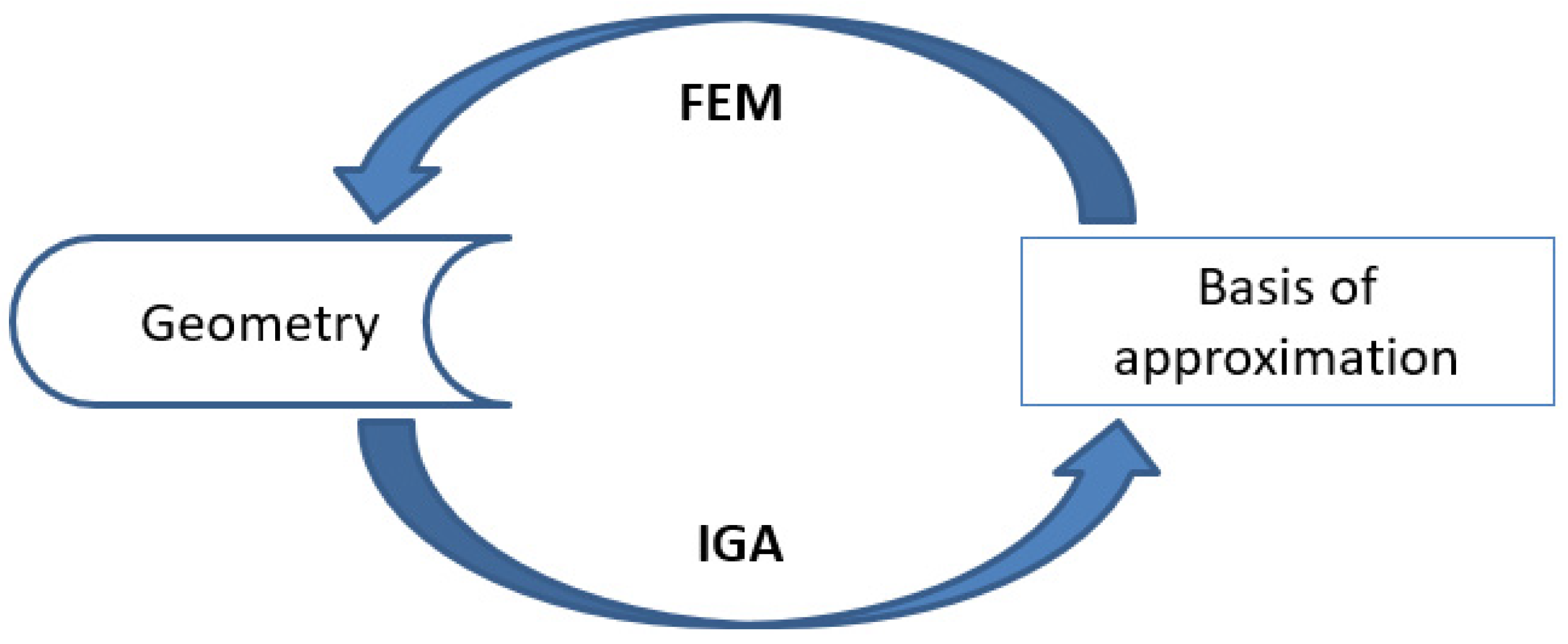
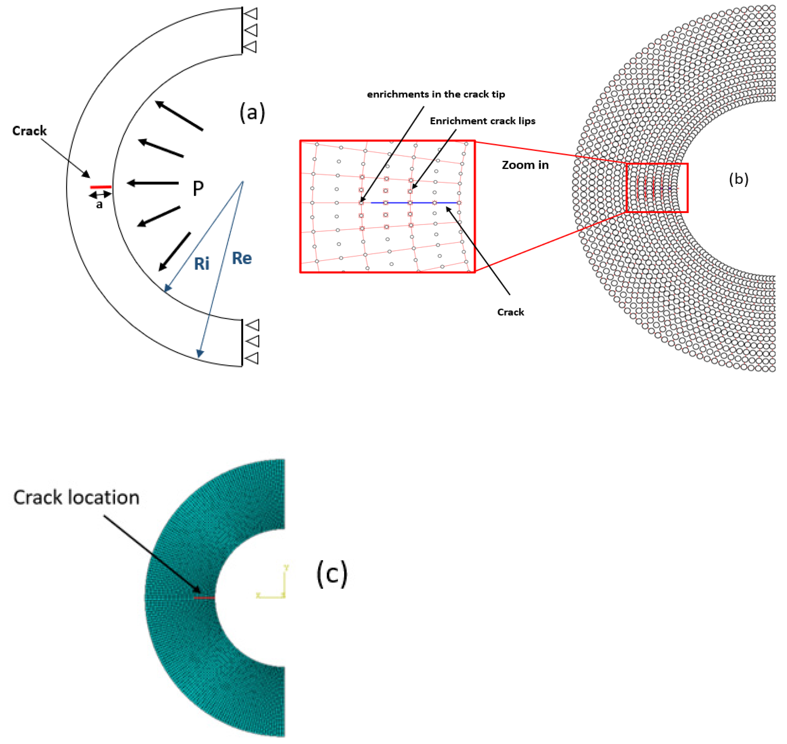
2.1. Extended Isogeometric Analysis
- Partition of unity: , signifying that the connection between the curve and its defining control points stays unchanged when subjected to affine transformation;
- Positivity: The basis functions are non-negative;
- Multiplicity: if internal knots are repeated m times, NURBS produces continuity of ;
- Linear independence: .
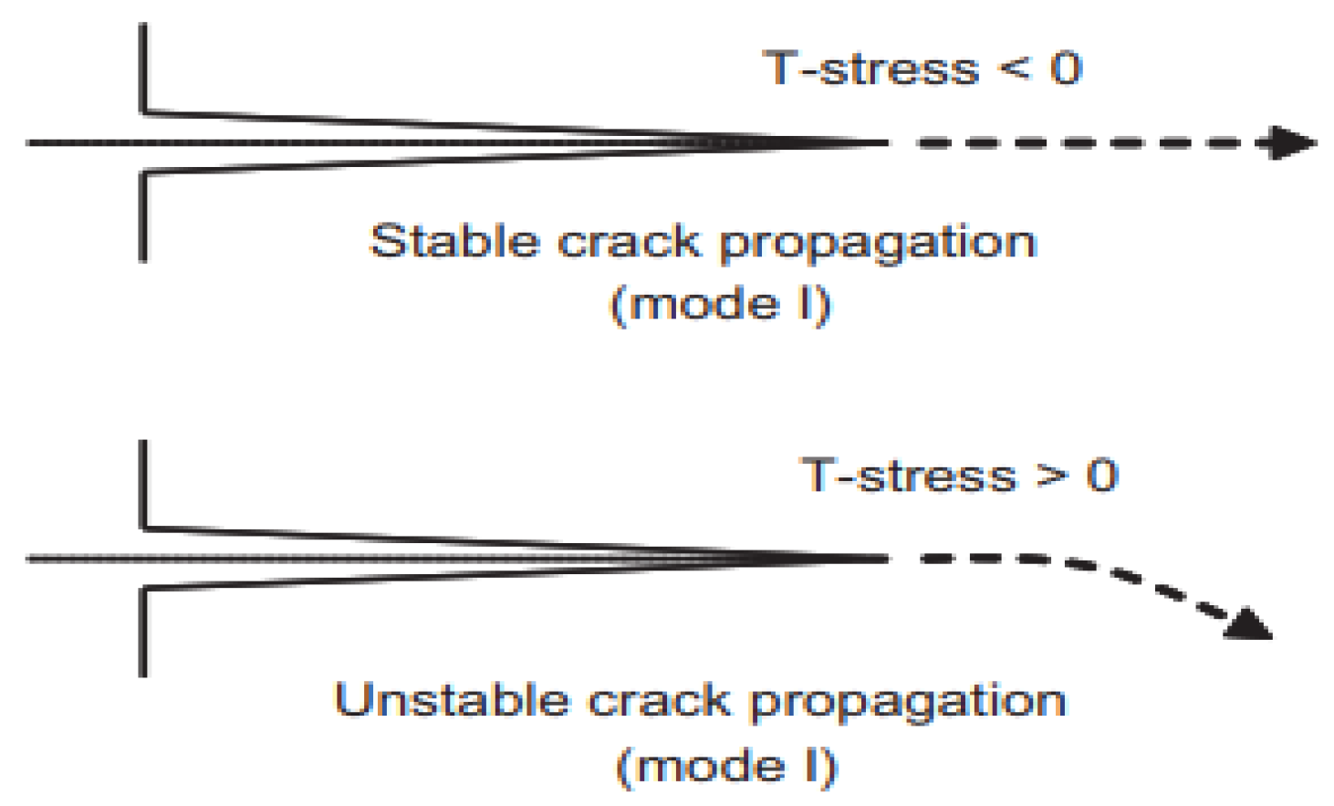
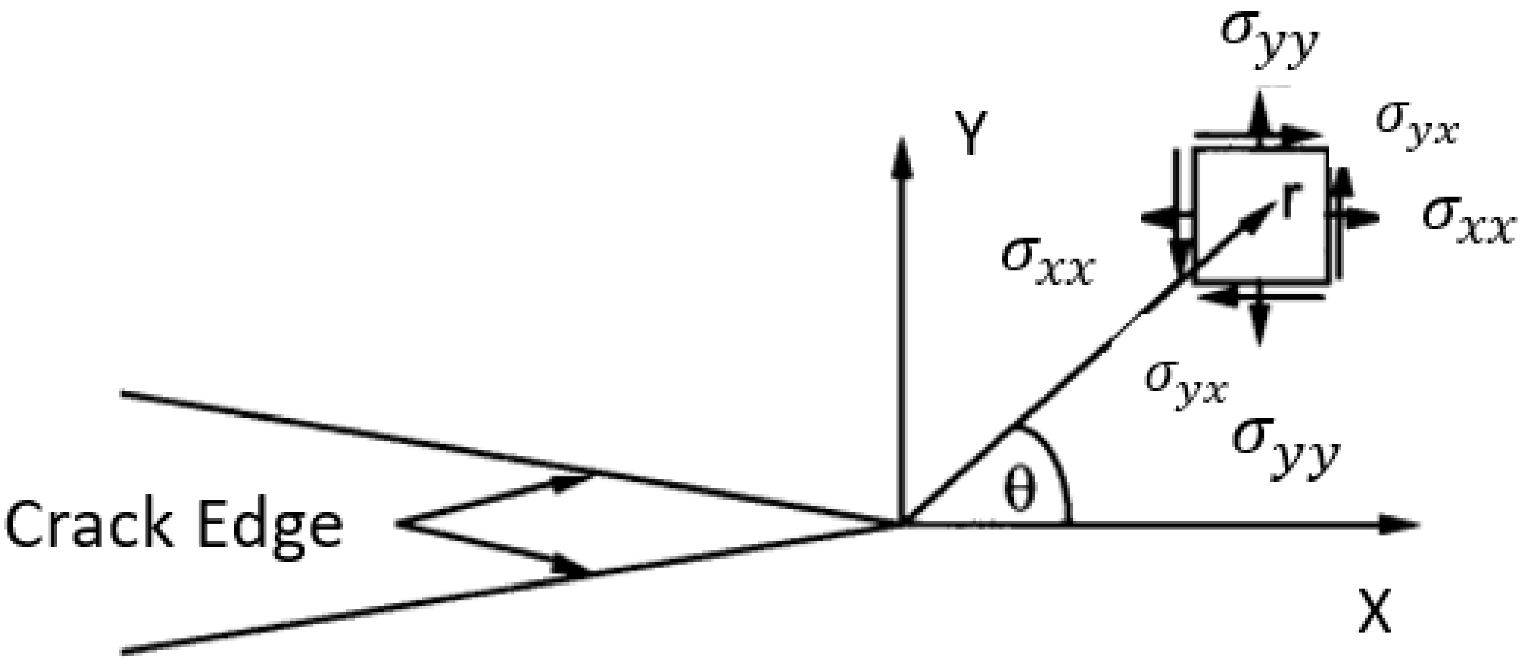
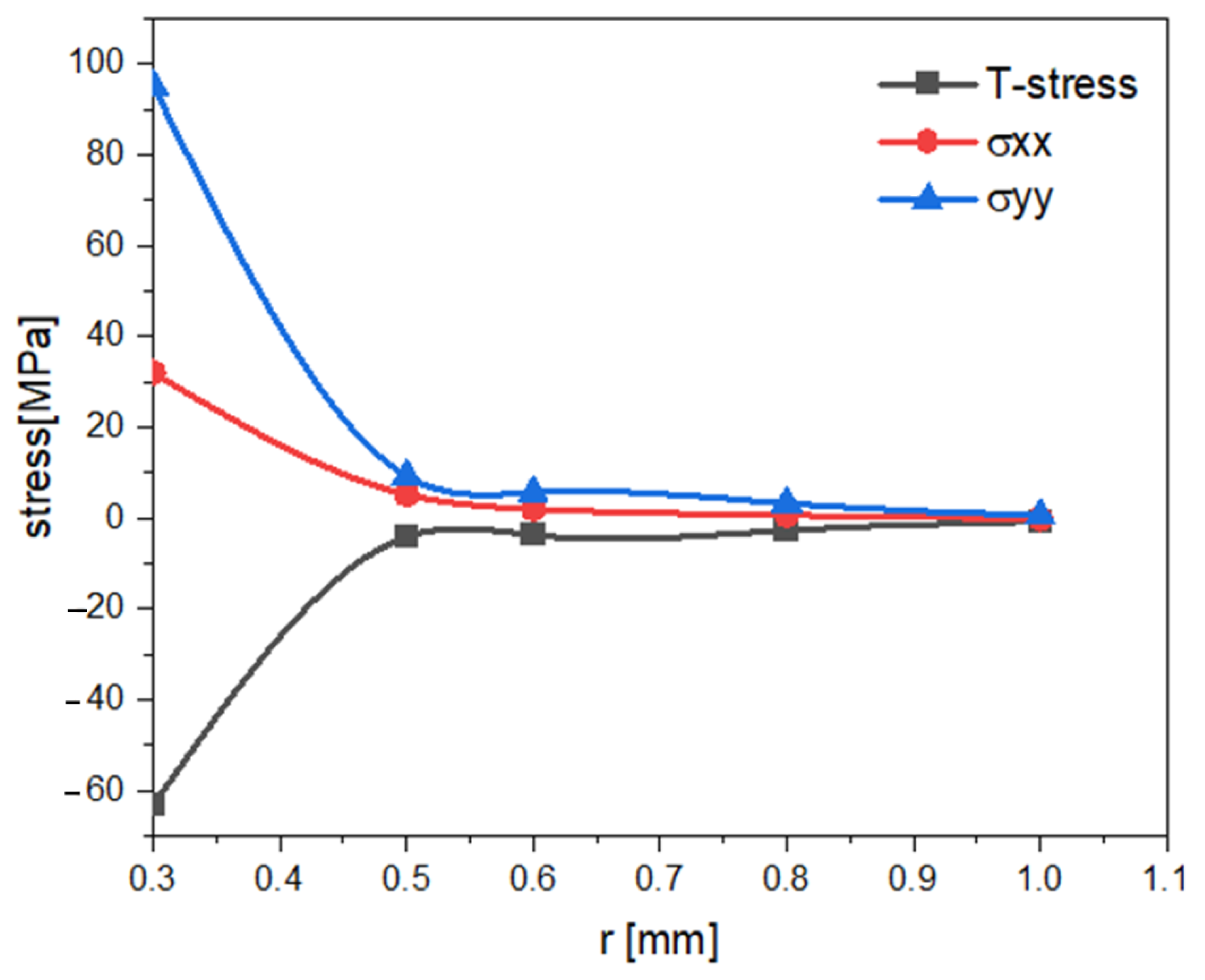
2.2. Computation of T-Stress
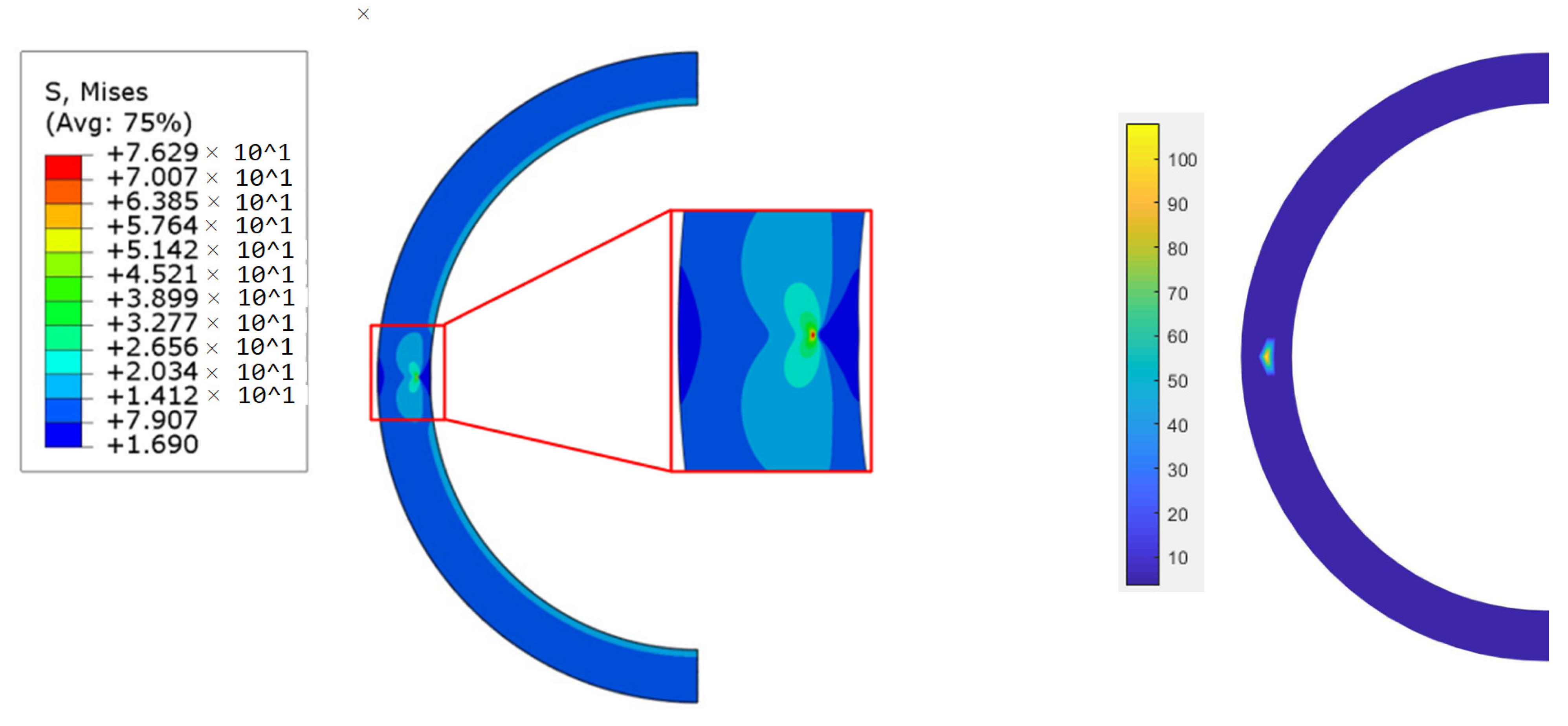
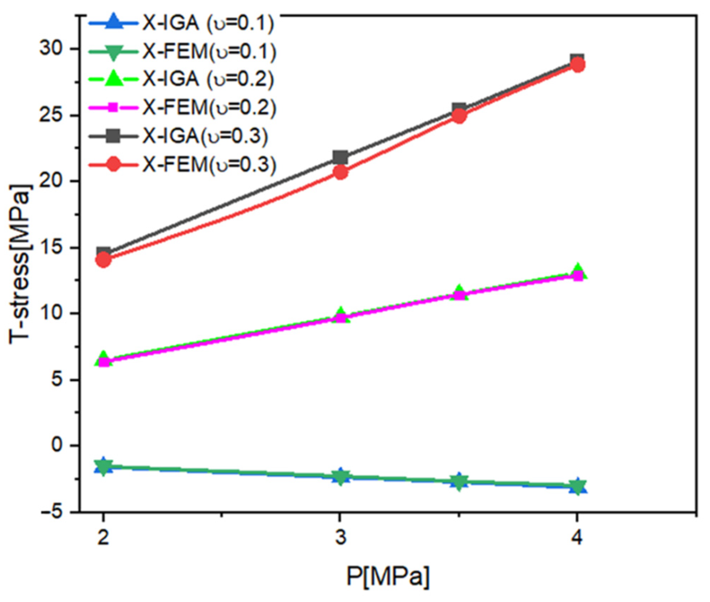
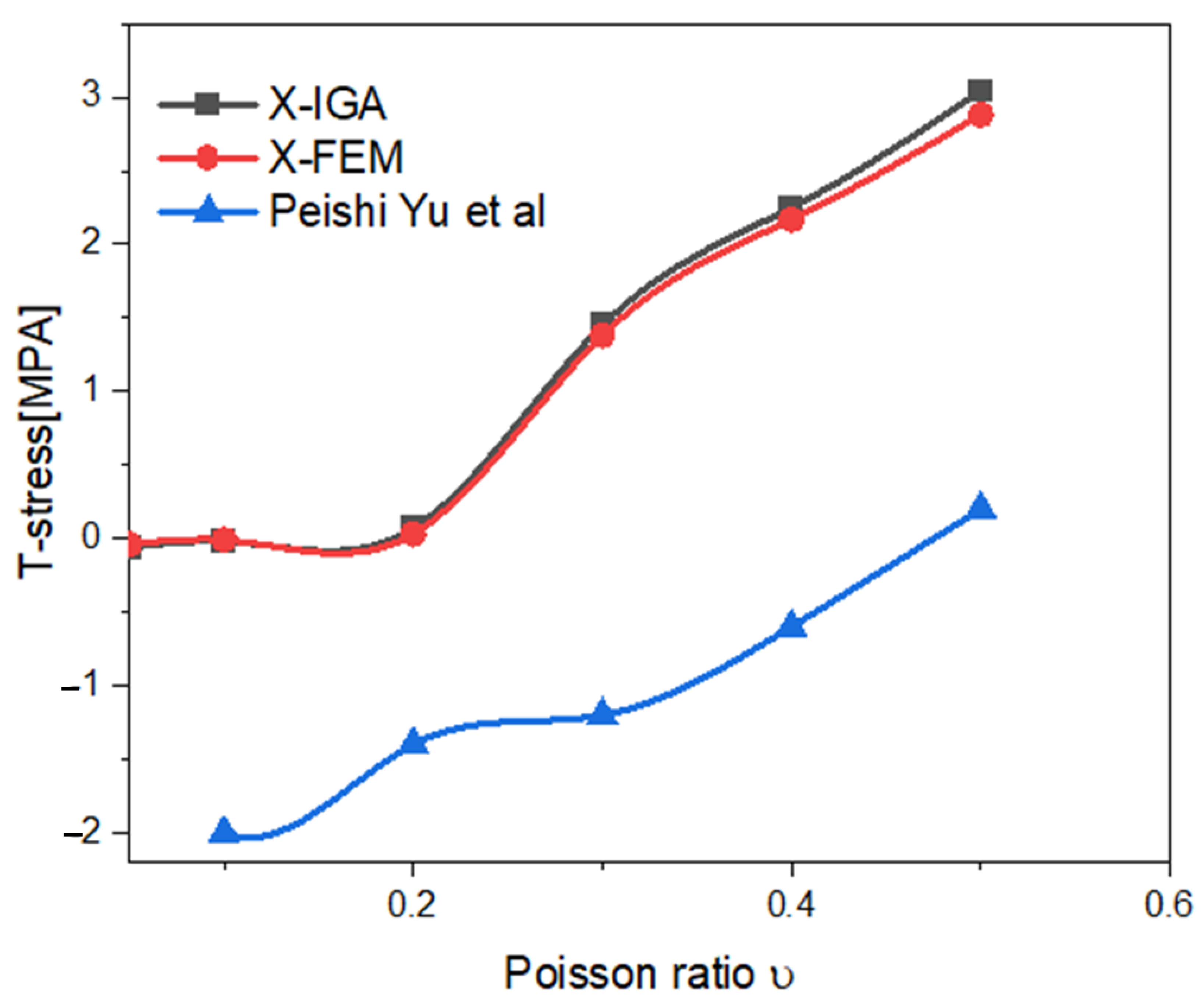
3. Results
4. Discussion
5. Conclusions
Author Contributions
Funding
Institutional Review Board Statement
Informed Consent Statement
Data Availability Statement
Acknowledgments
Conflicts of Interest
References
- Yakoubi, K.; Montassir, S.; Moustabchir, H.; Elkhalfi, A.; Pruncu, C.I.; Arbaoui, J.; Farooq, M.U. An Extended Finite Element Method (XFEM) Study on the Elastic T-Stress Evaluations for a Notch in a Pipe Steel Exposed to Internal Pressure. Mathematics 2021, 9, 507. [Google Scholar] [CrossRef]
- Shahani, A.; Tabatabaei, S. Effect of T-stress on the fracture of a four point bend specimen. Mater. Des. 2009, 30, 2630–2635. [Google Scholar] [CrossRef]
- Hou, C.; Wang, Z.; Jin, X.; Ji, X.; Fan, X. Determination of SIFs and T-stress using an over-deterministic method based on stress fields: Static and dynamic. Eng. Fract. Mech. 2021, 242, 107455. [Google Scholar] [CrossRef]
- Gupta, M.; Alderliesten, R.C.; Benedictus, R. A review of T-stress and its effects in fracture mechanics. Eng. Fract. Mech. 2015, 134, 218–241. [Google Scholar] [CrossRef]
- Lieurade, H.P.; Hariri, S. Estimation des Contraintes de Confinements dans des Structures Portant des Entailles. 2009, p. 320. Available online: https://hal.univ-lorraine.fr/tel-01752641/document (accessed on 16 May 2022).
- Song, C.; Ooi, E.T.; Natarajan, S. A review of the scaled boundary finite element method for two-dimensional linear elastic fracture mechanics. Eng. Fract. Mech. 2018, 187, 45–73. [Google Scholar] [CrossRef] [Green Version]
- Cotterell, B.; Rice, J. Slightly curved or kinked cracks. Int. J. Fract. 1980, 16, 155–169. [Google Scholar] [CrossRef]
- Miao, X.-T.; Zhou, C.-Y.; Lv, F.; He, X.-H. Three-dimensional finite element analyses of T-stress for different experimental specimens. Theor. Appl. Fract. Mech. 2017, 91, 116–125. [Google Scholar] [CrossRef]
- Suo, Y.-R.; Zhou, Y.-B.; Liu, G.-T. Effect of T-stress on the fracture in an infinite two-dimensional decagonal quasicrystals of a cruciform crack with unequal arms. Int. J. Solids Struct. 2021, 232, 111181. [Google Scholar] [CrossRef]
- Smith, D.; Ayatollahi, M.; Pavier, M. The role of T—stress in brittle fracture for linear elastic materials under mixed—mode loading. Fatigue Fract. Eng. Mater. Struct. 2001, 24, 137–150. [Google Scholar] [CrossRef]
- Mirsayar, M.M. On fracture of kinked interface cracks—The role of T-stress. Mater. Des. 2014, 61, 117–123. [Google Scholar] [CrossRef]
- Ayatollahi, M.R.; Aliha, M.R.M. Fracture toughness study for a brittle rock subjected to mixed mode I/II loading. Int. J. Rock Mech. Min. Sci. 2007, 44, 617–624. [Google Scholar] [CrossRef]
- Matvienko, Y.G. The effect of crack-tip constraint in some problems of fracture mechanics. Eng. Fail. Anal. 2020, 110, 104413. [Google Scholar] [CrossRef]
- Jayadevan, K.R.; Narasimhan, R.; Ramamurthy, T.S.; Dattaguru, B. Effect of T-stress and loading rate on crack initiation in rate sensitive plastic materials. Int. J. Solids Struct. 2002, 39, 1757–1775. [Google Scholar] [CrossRef]
- Ayatollahi, M.R.; Nejati, M.; Ghouli, S. The finite element over-deterministic method to calculate the coefficients of crack tip asymptotic fields in anisotropic planes. Eng. Fract. Mech. 2020, 231, 106982. [Google Scholar] [CrossRef]
- Cottrell, J.A.; Hughes, T.J.R.; Bazilevs, Y. Isogeometric Analysis Toward Integration of CAD and FEA; John Wiley & Sons: London, UK, 2009. [Google Scholar]
- Hughes, T.J.R.; Cottrell, J.A.; Bazilevs, Y. Isogeometric analysis: CAD, finite elements, NURBS, exact geometry and mesh refinement. Comput. Methods Appl. Mech. Eng. 2005, 194, 4135–4195. [Google Scholar] [CrossRef] [Green Version]
- Lai, W.; Yu, T.; Bui, T.Q.; Wang, Z.; Curiel-Sosa, J.L.; Das, R.; Hirose, S. 3-D elasto-plastic large deformations: IGA simulation by Bézier extraction of NURBS. Adv. Eng. Softw. 2017, 108, 68–82. [Google Scholar] [CrossRef] [Green Version]
- El Fakkoussi, S.; Moustabchir, H.; Elkhalfi, A.; Pruncu, C.I. Application of the Extended Isogeometric Analysis (X-IGA) to Evaluate a Pipeline Structure Containing an External Crack. J. Eng. 2018, 2018, 4125765. [Google Scholar] [CrossRef] [Green Version]
- Montassir, S.; Moustabchir, H.; Elkhalfi, A.; Scutaru, M.L.; Vlase, S. Fracture Modelling of a Cracked Pressurized Cylindrical Structure by Using Extended Iso-Geometric Analysis (X-IGA). Mathematics 2021, 9, 2990. [Google Scholar] [CrossRef]
- Yixiu, S.; Yazhi, L. A Simple and Efficient X-FEM Approach for Non-planar Fatigue Crack Propagation. Procedia Struct. Integr. 2016, 2, 2550–2557. [Google Scholar] [CrossRef] [Green Version]
- Schiavone, A. Abeygunawardana-Arachchige, G.; Silberschmidt, V.V. Crack initiation and propagation in ductile specimens with notches: Experimental and numerical study. Acta Mech. 2016, 227, 203–215. [Google Scholar] [CrossRef] [Green Version]
- Cottrell, J.A.; Reali, A.; Bazilevs, Y.; Hughes, T.J.R. Isogeometric analysis of structural vibrations. Comput. Methods Appl. Mech. Eng. 2006, 195, 5257–5296. [Google Scholar] [CrossRef] [Green Version]
- Shojaee, S.; Valizadeh, N.; Izadpanah, E.; Bui, T.; Vu, T.-V. Free vibration and buckling analysis of laminated composite plates using the NURBS-based isogeometric finite element method. Compos. Struct. 2012, 94, 1677–1693. [Google Scholar] [CrossRef]
- Kapoor, H.; Kapania, R.K. Geometrically nonlinear NURBS isogeometric finite element analysis of laminated composite plates. Compos. Struct. 2012, 94, 3434–3447. [Google Scholar] [CrossRef]
- Wang, Y.; Wang, Z.; Xia, Z.; Hien Poh, L. Structural Design Optimization Using Isogeometric Analysis: A Comprehensive Review. Comput. Model. Eng. Sci. 2018, 117, 455–507. [Google Scholar] [CrossRef] [Green Version]
- Yadav, A.; Godara, R.K.; Bhardwaj, G. A review on XIGA method for computational fracture mechanics applications. Eng. Fract. Mech. 2020, 230, 107001. [Google Scholar] [CrossRef]
- Nguyen-Thanh, N.; Valizadeh, N.; Nguyen, M.N.; Nguyen-Xuan, H.; Zhuang, X.; Areias, P.; Zi, G.; Bazilevs, Y.; De Lorenzis, L.; Rabczuk, T. An extended isogeometric thin shell analysis based on Kirchhoff–Love theory. Comput. Methods Appl. Mech. Eng. 2015, 284, 265–291. [Google Scholar] [CrossRef]
- Hou, W.; Jiang, K.; Zhu, X.; Shen, Y.; Hu, P. Extended isogeometric analysis using B++ splines for strong discontinuous problems. Comput. Methods Appl. Mech. Eng. 2021, 381, 113779. [Google Scholar] [CrossRef]
- Singh, S.K.; Singh, I.V.; Mishra, B.K.; Bhardwaj, G.; Bui, T.Q. A simple, efficient and accurate Bézier extraction based T-spline XIGA for crack simulations. Theor. Appl. Fract. Mech. 2017, 88, 74–96. [Google Scholar] [CrossRef]
- Ghorashi, S.S.; Valizadeh, N.; Mohammadi, S. Extended isogeometric analysis for simulation of stationary and propagating cracks: Xiga for simulation of stationary and propagating cracks. Int. J. Numer. Methods Eng. 2012, 89, 1069–1101. [Google Scholar] [CrossRef]
- El Fakkoussi, S.; Moustabchir, H.; Elkhalfi, A.; Pruncu, C.I. Computation of the stress intensity factor KI for external longitudinal semi-elliptic cracks in the pipelines by FEM and XFEM methods. Int. J. Interact. Des. Manuf. IJIDeM 2019, 13, 545–555. [Google Scholar] [CrossRef] [Green Version]
- Kfouri, A.P. Some evaluations of the elastic T-term using Eshelby’s method. Int. J. Fract. 1986, 30, 301–315. [Google Scholar] [CrossRef]
- Yang, B.; Ravi-Chandar, K. Evaluation of elastic T-stress by the stress difference method. Eng. Fract. Mech. 1999, 64, 589–605. [Google Scholar] [CrossRef]
- Rungamornrat, J.; Mear, M.E. A weakly-singular SGBEM for analysis of cracks in 3D anisotropic media. Comput. Methods Appl. Mech. Eng. 2008, 197, 4319–4332. [Google Scholar] [CrossRef]
- Phongtinnaboot, W.; Rungamornrat, J.; Chintanapakdee, C. Modeling of cracks in 3D piezoelectric finite media by weakly singular SGBEM. Eng. Anal. Bound. Elem. 2011, 35, 319–329. [Google Scholar] [CrossRef]
- Ghorashi, S.S.; Mohammadi, S.; Sabbagh-Yazdi, S.-R. Orthotropic enriched element free Galerkin method for fracture analysis of composites. Eng. Fract. Mech. 2011, 78, 1906–1927. [Google Scholar] [CrossRef]
- Li, J.; Liu, J.Z.; Korakianitis, T.; Wen, P.H. Finite block method in fracture analysis with functionally graded materials. Eng. Anal. Bound. Elem. 2017, 82, 57–67. [Google Scholar] [CrossRef]
- Fallah, N.; Nikraftar, N. Meshless finite volume method for the analysis of fracture problems in orthotropic media. Eng. Fract. Mech. 2018, 204, 46–62. [Google Scholar] [CrossRef]
- Kim, J.-H.; Paulino, G.H. T-stress, mixed-mode stress intensity factors, and crack initiation angles in functionally graded materials: A unified approach using the interaction integral method. Comput. Methods Appl. Mech. Eng. 2003, 192, 1463–1494. [Google Scholar] [CrossRef]
- Shah, P.D.; Tan, C.L.; Wang, X. T-stress solutions for two-dimensional crack problems in anisotropic elasticity using the boundary element method. Fatigue Fract. Eng. Mater. Struct. 2006, 29, 343–356. [Google Scholar] [CrossRef]
- Nguyen-Thanh, N.; Zhou, K. Extended isogeometric analysis based on PHT-splines for crack propagation near inclusions. Int. J. Numer. Methods Eng. 2017, 112, 1777–1800. [Google Scholar] [CrossRef]
- Yang, H.S.; Dong, C.Y. Adaptive extended isogeometric analysis based on PHT-splines for thin cracked plates and shells with Kirchhoff–Love theory. Appl. Math. Model. 2019, 76, 759–799. [Google Scholar] [CrossRef]
- Singh, S.K.; Singh, I.V. Extended isogeometric analysis for fracture in functionally graded magneto-electro-elastic material. Eng. Fract. Mech. 2021, 247, 107640. [Google Scholar] [CrossRef]
- Sladek, J.; Sladek, V. Evaluation of the Elastic T-stress in Three-dimensional Crack Problems Using an Integral Formula. Int. J. Fract. 2000, 101, 47–52. [Google Scholar] [CrossRef]
- Toshio, N.; Parks, D.M. Determination of elastic T-stress along three-dimensional crack fronts using an interaction integral. Int. J. Solids Struct. 1992, 29, 1597–1611. [Google Scholar] [CrossRef]
- Yu, P.; Wang, Q.; Zhang, C.; Zhao, J. Elastic T -stress and I-II mixed mode stress intensity factors for a through-wall crack in an inner-pressured pipe. Int. J. Press. Vessels Pip. 2018, 159, 67–72. [Google Scholar] [CrossRef]
- Wang, X. Elastic T-stress solutions for semi-elliptical surface cracks in finite thickness plates. Eng. Fract. Mech. 2003, 70, 731–756. [Google Scholar] [CrossRef]
- Sham, T.-L. The determination of the elastic T-term using higher order weight functions. Int. J. Fract. 1991, 48, 81–102. [Google Scholar] [CrossRef]
- Brugier, F. Modèle Condensé de Plasticité Pour la Fissuration et Influence de la Contrainte T; Université Paris-Saclay (ComUE): Paris, France, 2017; Available online: https://tel.archives-ouvertes.fr/tel-01587740/file/74336_BRUGIER_2017_archivage.pdf (accessed on 16 May 2022).


| Young’s Modulus | Poisson’s Ratio | Yield Stress | Elongation to Fracture |
|---|---|---|---|
| 207,000 MPa | 0.3 | 340 MPa | 35% |
| Material | C | Mn | S | Si | p | Al |
|---|---|---|---|---|---|---|
| Tested | 0.135 | 0.665 | 0.002 | 0.195 | 0.027 | 0.027 |
| Steel P264GH (Standard EN10028.2-92) | 0.18 | 1 | 0.015 | 0.4 | 0.025 | 0.02 |
| Ri [mm] | p [MPa] | a [mm] | t [mm] |
|---|---|---|---|
| 100 | 2.5 | 3–5 | 20 |
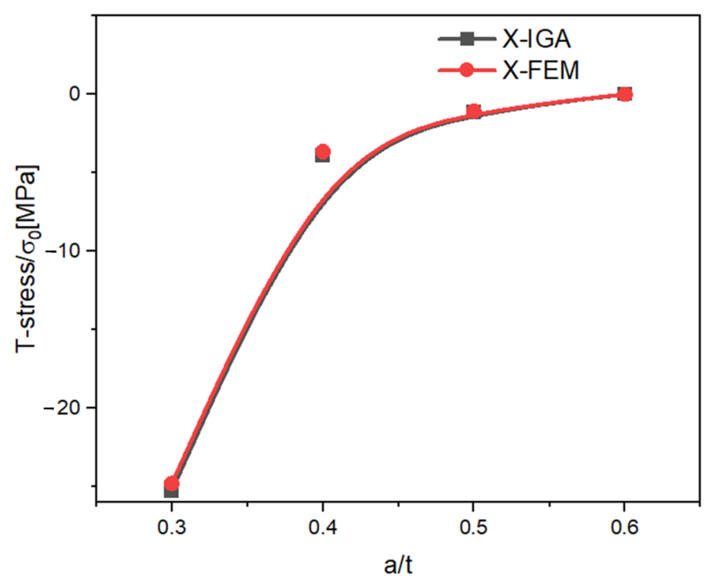
| X-IGA | X-FEM | Error [%] | |
|---|---|---|---|
| 0.3 | −25.26 | −25.00 | 0.12 |
| 0.4 | −3.89 | −3.81 | 2.09 |
| 0.5 | −1.14 | −1.11 | 3.6 |
| 0.6 | −10−4 | 4 × 10⁻⁴ | −zv |
Publisher’s Note: MDPI stays neutral with regard to jurisdictional claims in published maps and institutional affiliations. |
© 2022 by the authors. Licensee MDPI, Basel, Switzerland. This article is an open access article distributed under the terms and conditions of the Creative Commons Attribution (CC BY) license (https://creativecommons.org/licenses/by/4.0/).
Share and Cite
Yakoubi, K.; Montassir, S.; Moustabchir, H.; Elkhalfi, A.; Scutaru, M.L.; Vlase, S. T-Stress Evaluation Based Cracking of Pipes Using an Extended Isogeometric Analysis (X-IGA). Symmetry 2022, 14, 1065. https://0-doi-org.brum.beds.ac.uk/10.3390/sym14051065
Yakoubi K, Montassir S, Moustabchir H, Elkhalfi A, Scutaru ML, Vlase S. T-Stress Evaluation Based Cracking of Pipes Using an Extended Isogeometric Analysis (X-IGA). Symmetry. 2022; 14(5):1065. https://0-doi-org.brum.beds.ac.uk/10.3390/sym14051065
Chicago/Turabian StyleYakoubi, Khadija, Soufiane Montassir, Hassane Moustabchir, Ahmed Elkhalfi, Maria Luminita Scutaru, and Sorin Vlase. 2022. "T-Stress Evaluation Based Cracking of Pipes Using an Extended Isogeometric Analysis (X-IGA)" Symmetry 14, no. 5: 1065. https://0-doi-org.brum.beds.ac.uk/10.3390/sym14051065