
Performance Analysis of Continuous Variable Quantum Teleportation with Noiseless Linear Amplifier in Seawater Channel


1
School of Automation, Central South University, Changsha 410083, China
2
School of Computer Science, Beijing University of Posts and Telecommunications, Beijing 100876, China
*
Authors to whom correspondence should be addressed.
†
These authors contributed equally to this work.
Symmetry 2022, 14(5), 997; https://0-doi-org.brum.beds.ac.uk/10.3390/sym14050997
Submission received: 28 March 2022
/
Revised: 4 May 2022
/
Accepted: 6 May 2022
/
Published: 13 May 2022
(This article belongs to the Special Issue Symmetry and Asymmetry in Quantum Cryptography)
Abstract
:Continuous variable quantum teleportation (CVQT) is one of the technologies currently explored to implement global quantum networks. Entanglement source is an indispensable resource to realize CVQT, and its distribution process has natural symmetry. Though there are many results for CVQT over optical fiber or atmospheric channel, little attention is paid to seawater channel. In this paper, a model based on seawater chlorophyll concentration is used to study the attenuation effect of seawater on light. In our scheme, a noiseless linear amplifier is utilized for enhancing the performance of CVQT under seawater channel. Simulation results show that the proposed scheme has an improvement in terms of fidelity and maximum transmission distance compared with the original scheme.
1. Introduction
Quantum teleportation (QT) is an important way of quantum communication, which can transport an unknown quantum state to a distant place without transmitting the physical carrier itself by using the entanglement properties of quantum mechanics. In 1993, Bennett et al. pioneered the discrete-variable quantum telepotation (DVQT) protocol [1,2,3], which opened the door for the research of QT. After that, a large number of scholars have carried out theoretical analysis and experimental investigation on DVQT, and made great breakthroughs in optical fiber and free space [4,5,6]. Although optical qubits have been used as an important carrier for long-distance quantum teleportation, accurate single-photon source preparation is difficult to make, and single-photon detector is expensive. Fortunately, shortly after the DVQT protocol was proposed, quantum teleportation was extended to continuous variable systems. Different from DVQT, in continuous-variable quantum teleportation (CVQT) [7,8,9], the preparation process of quantum signal is simple and the detectors are commercially available. Quantum states such as coherent state and squeezed state can be used for carriers of information. The balanced homodyne detection that is usually used for classical optical communication can be employed in CVQT. In addition, CVQT has better compatibility with classical optical communication system and thus has many advantages in practical application.
In CVQT, the most famous protocol is proposed by Braunstein and Kimble in 1998, which is called BK protocol [7]. The sender (Alice) uses the shared two mode squeezed vacuum state as the carrier to transfer the unknown quantum state to the receiver (Bob), and sends the measurement results to Bob through classical communication. Bob measures the unknown quantum state according to the classical information. However, the ideal infinite squeezed state can not be realized physically, and the interaction between the quantum system and the surrounding environment inevitably leads to the degradation of quantum coherence and entanglement.
The lossy channel of CVQT system has been gradually extended from the initial fiber channel [3,10,11] to the free-space atmosphere channel [12,13], which has been verified [14,15,16,17,18]. Since the attenuation of seawater is more serious than that of optical fiber and atmospheric channel, the practicability of seawater as a communication medium is reduced. However, with the gradual maturity of quantum communication technology, the free-space quantum communication in seawater has attracted much attention for its indispensable role in constructing the global quantum communication network [19,20]. In the recent experimental studies, Ji et al. [21] collected seawater from the Yellow Sea as experimental seawater and realized the transmission of polarization-encoded quantum states and quantum entanglement in a 3.3 m long glass pipe. Hu et al. [22] experimentally demonstrated the transmission of blue-green photonic polarization states through 55 m long water.
In this paper, the attenuation effect of seawater on light varying with seawater depth is observed in the calculations, which is based on the chlorophyll-a concentration model [23,24,25], and consider the background light noise in seawater [26,27]. In addition, a noiseless linear amplifier (NLA) is employed for the receiver to improve the system performance of the CVQT system. On the one hand, the addition of NLA can compensate the attenuation of the seawater channel, but on the other the effect of NLA on excess noise is minimal and the impact of the increased excess noise on system performance can be ignored. The numerical simulations show that performance of CVQT system can be improved by the embedded NLA in the receiver, which make the CVQT has a wider range of applications.
The organization of this paper is as follows. In Section 2, we suggest the schematic diagram of the NLA-based CVQT in detail, where the optical transmission characteristics of seawater and the attenuation distribution of light signal are simulated. In Section 3, the effect of the excess noise on the system is shown. In Section 4, the performance of the the NLA-based CVQT system is analyzed in terms of the fidelity and maximal transmission distance. Finally, the conclusion is drawn in Section 5.
2. The NLA-Based CVQT under Seawater
In this section, we propose the NLA-based CVQT system under seawater. Then, the optical propagation characteristics of the seawater channel is demonstrated for the CVQT system.
2.1. The NLA-Based CVQT Protocol
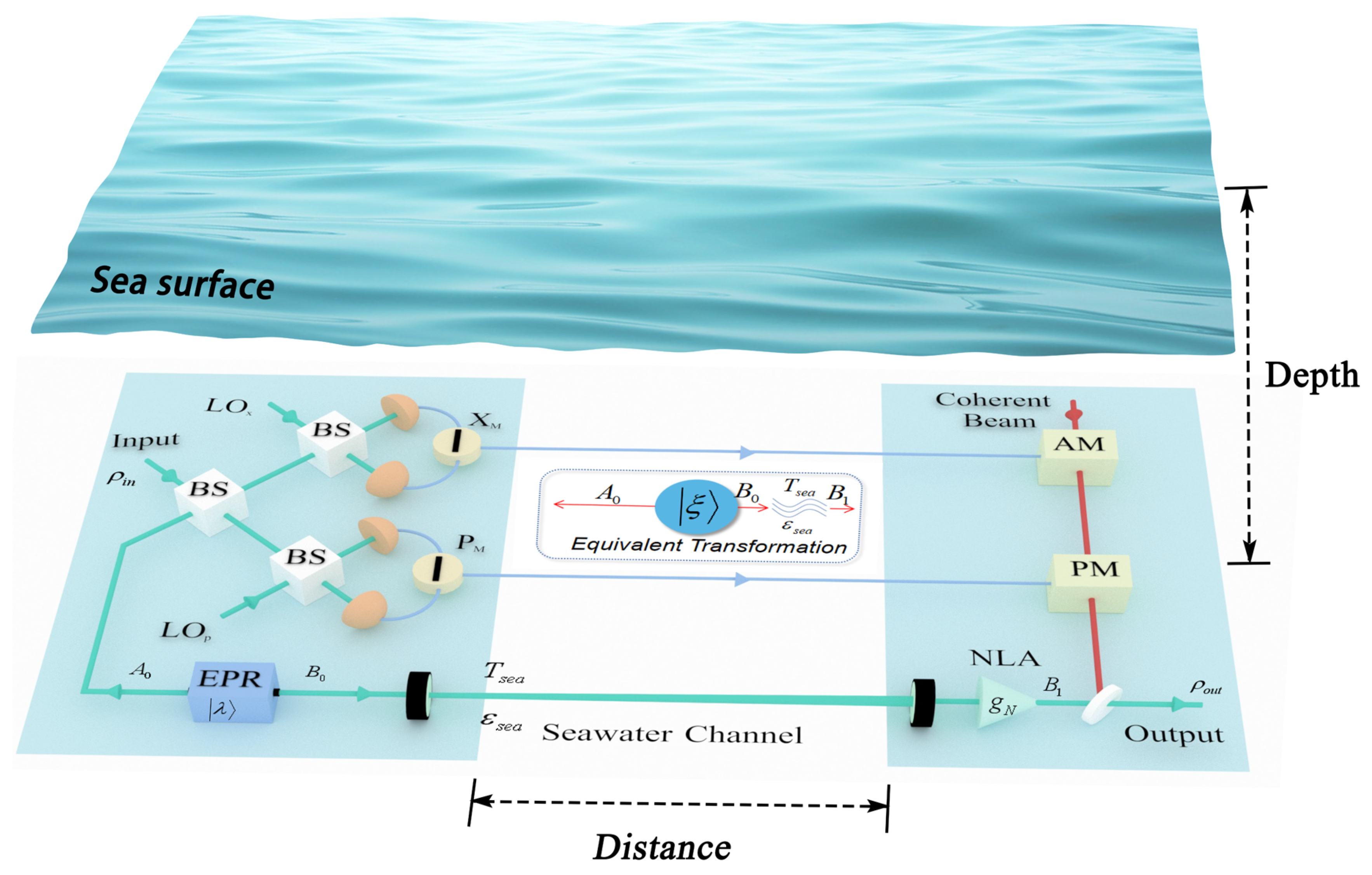
The entanglement-based (EB) scheme of the proposed NLA-CVQT protocol is shown in Figure 1. The implementation of this scheme can be described as follows.
Step 1: Alice prepares the EPR state, which contains modes and . The mode is sent to Bob through a seawater channel, and the mode is retained by Alice.
Step 2: After receiving the mode , Bob performs NLA amplification on the received mode to transform it to mode , where the amplification gain is . Meanwhile, Alice mixes an unknown input state with the mode through a 50:50 beam splitter, and then performs continuous variable Bell measurement on the output mode to obtain the measurement results , of the quadratures x and p.
Step 3: Because of the entanglement property of the EPR state, the measurement of Alice can make the input state project to the mode, and there is only a phase space shift deviation between the two states. Therefore, Alice sends the measurement result to Bob through the classical channel, then Bob performs a displacement operation on the mode according to the measurement result, and finally obtains a copy of the input state.
Step 4: So far, though the input state has not been sent directly, the transfer of quantum state from Alice to Bob has been completed and the process of quantum teleportation has been realized. It should be noted that this process is not a clone of the input state , because Alice’s Bell measurement will destroy itself. Therefore, this process does not violate the no-cloning theorem. In addition, this process requires the participation of classical communication, but not superluminal communication, so it does not violate the principle of relativity.
As for the CVQT protocol, an important index to evaluate the performance of the system is the fidelity [28], which characterizes the proximity between the input state and the output state, given by [29]
When the input state is a pure state, the fidelity can be calculated by the superposition integral of the characteristic functions of the input state and the output state, and thus the above mentioned fidelity can be written as [30]
where and are the characteristic functions (Fourier transform of the Wigner function) of the input state and the output state, respectively.
In our scheme, the coherent state is considered as the input state. Since the teleportation is invariant under the displacement transformation, that is to say, it has the same covariance matrix before and after the transformation, and all states of different coherent components are teleported with the same fidelity. Therefore, the vacuum state with zero coherence amplitude can be chosen as the input state in the calculation of the eigenfunction . The eigenfunction of the output state can be calculated by the eigenfunction of the input state and the entanglement source eigenfunction, namely . The eigenfunction of the EPR state can be calculated as
where is the modulation variance of the EPR state and is the inherent parameters of the entanglement source. After the EPR state passing through the lossy channel, the characteristic function transforms to
where , and . In addition, and are the transmittance and excess noise of the mode over seawater channel, respectively, while and are the corresponding accounts of the mode . Since the EPR state is prepared by Alice, the transmission process of modes can be considered lossless, so we have = 1 and = 0.
As a result, the fidelity of the CVQT system is mainly affected by the transmittance , the excess noise , and the inherent parameters .
2.2. Optical Propagation Characteristics of Seawater Channel
Optical transmission window of seawater on blue-green light provides an opportunity to realize underwater low-attenuation optical communication [26]. However, the composition of seawater changes with many factors such as environment and region, and it is difficult to use a general model to study its propagation characteristics in detail. Here, we consider the effects of light absorption and light scattering on CVQT system performance. Absorption and scattering are known to cause loss of light intensity and beam deflection. Thus, the energy of the optical signal received by the receiver is constantly attenuated.
Without loss of generality, the current quantum communication based on seawater channel has a short transmission distance (generally <55 m [21,22,31]), so we assumed that seawater channel is a linear channel, that is, the attenuation coefficient is determined for a certain fixed depth and wavelength. The absorption coefficient is a function of depth d and wavelength , namely [32,33]
where first term is the wavelength-dependent absorption coefficient of pure seawater, the second item is the absorption coefficient related to chlorophyll-a, the third term represents the absorption coefficient of fulvic acid, the fourth item represents the absorption coefficient of humic acid, the fifth item represents the absorption coefficient of mineral and detritus. The specific parameter settings are shown in Appendix A.
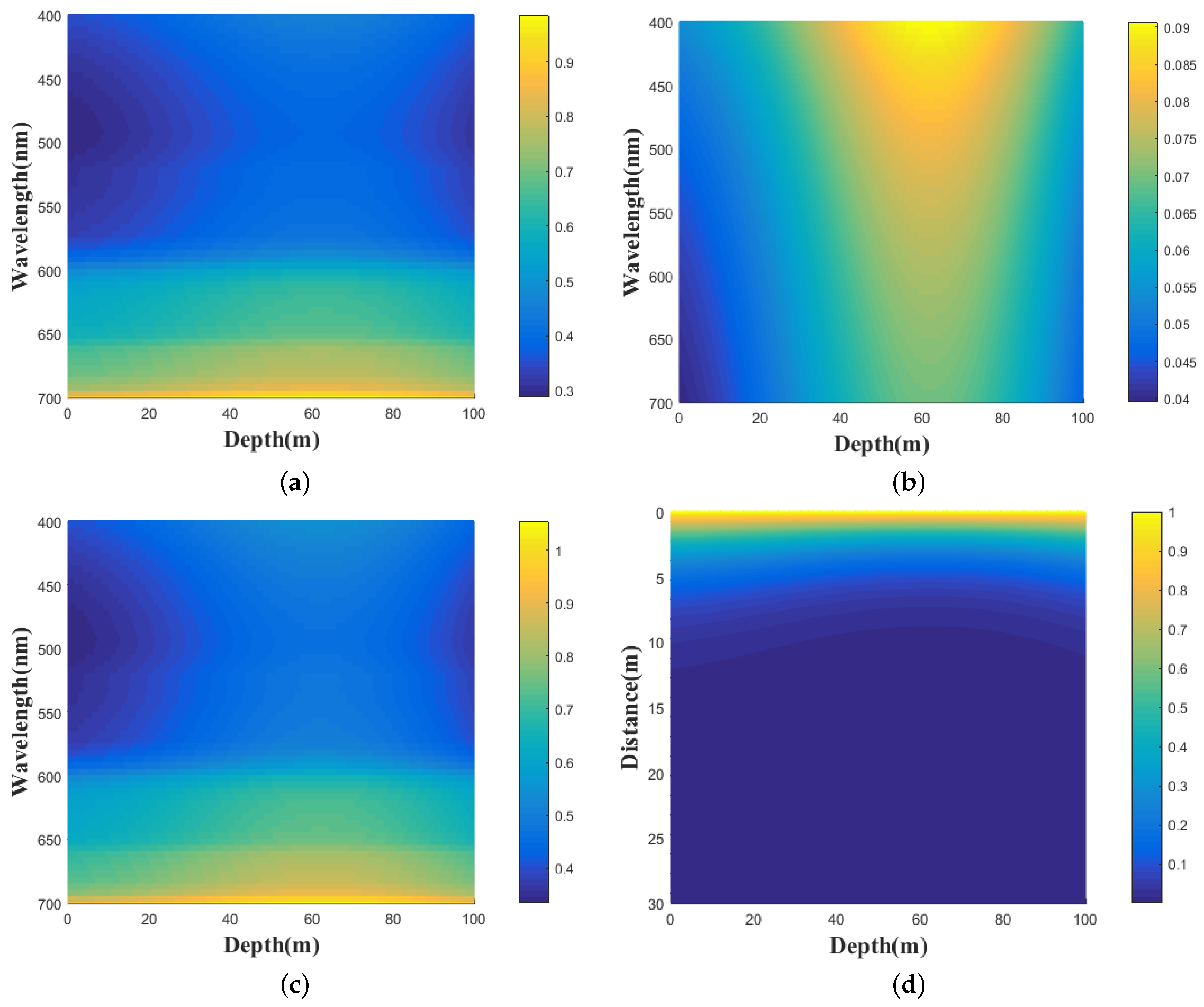
The absorption coefficient , seawater depth d and wavelength are simulated as shown in Figure 2a, where is characterized by the color and its unit is m. We find that with the increase of seawater depth, the absorption coefficient first increasing and then decreasing, reaching a peak from 40 m to 80 m, which is due to phytoplankton, colored dissolved organic matter and particulate minerals mainly enriched at this depth interval [33].
The scattering coefficient is also the function of depth d and wavelength , which can be written as [25]
where first term is the wavelength-dependent scattering coefficient of pure seawater, the second item represents the scattering coefficient of small particles, the third term represents the scattering coefficient of large particles. The specific parameter settings are shown in Appendix B.
The scattering coefficient , seawater depth d and wavelength are simulated as shown in Figure 2b, where is characterized by the color and its unit also is m. We find that the scattering coefficient increases at the beginning, and then decreases with increasing depth, but it gradually decreases with increasing wavelength.
The total seawater channel attenuation can be derived as
The total attenuation coefficient , seawater depth d and wavelength are simulated as shown in Figure 2c, where is represented by the color. The change of the total attenuation coefficient to seawater depth is similar to that of the absorption coefficient. However, a low-loss interval appears in the wavelength range of 450–550 nm, which is precisely due to the optical transmission window effect. Therefore, we choose the 520 nm [34] wavelength beam as the communication beam to analyze the CVQT protocol performance.
It can be seen from the above analysis that the total attenuation changes nonlinearly with the seawater depth. Therefore, we discuss the situation when light travels in a horizontal plane at the same depth for simplicity, the transmittance as a function of total attenuation coefficient and horizontal transmission distance L can be expressed as
The transmittance , total attenuation coefficient and horizontal transmission distance L are simulated as shown in Figure 2d. We find that the transmittance slowly decreases and then increases with increasing depth, but it decreases rapidly with the increase of transmission distance.
3. Effect of Excess Noise
Generally, the initial excess noise of Gaussian modulated states is about 0.01 in shot-noise units (SNU) [35]. However, due to the existence of background light noise in seawater, the actual excess noise of the received states may be larger than this initial excess noise [36,37]. Most of the background light noise in seawater comes from the air (sun and sky). About of this light enters seawater and is absorbed by phytoplankton at various depths [26,37]. For practical purposes, we assume that there is a virtual telescope at the Bob to receive the light signal. Therefore, the background light noise underwater can be written as
where and m are the field of view and the radius of the virtual telescope, respectively. is the filter bandwidth, the value of which is primarily determined by the laser that produces the local oscillator. We can take the error range of the laser as nm, which means nm. The solar radiance is given by
where is the brightness of the sky background in , and it is closely related to the weather conditions. The typical brightness on a moonless and clear night is and the clear daytime is [37]. In addition, is the underwater reflectance of the downwelling irradiance . is the element related to the directional dependence of the underwater radiance, c is the total attenuation coefficient in seawater, and d is the depth. Finally, the total excess noise is given by
where h denotes Planck’s constant, and is the frequency of the noise photons. The frequency of homodyne detector is 1 GHz, and thus ns.
Figure 3 shows the variation of background light noise with depth under different light transmission conditions. The red solid lines and blue solid lines represent the variation of background light noise with depth in clear day and moonless night, respectively, and the filled region represents the possible background light noise values. It can be seen that there is an order of magnitude difference in the background light noise between the two extreme cases. The background noise attenuates exponentially with the increase of depth, and the attenuation degree decreases gradually. When the depth is greater than 50 m, the noise is negligible.
4. Performance Analysis
In this section, we consider the equivalent transformation of the seawater channel parameters after adding a tunable NLA at Bob’s side. Taking into account the gain constraints of NLA, the performance of the CVQT system is evaluated within the available gain range.
4.1. The Gain of NLA under Seawater Channel
In quantum communication systems, a suitable NLA can be used to compensate for channel loss, thereby improving the fidelity of quantum signals and lengthening the maximum transmission distance. Therefore, we employ a tunable NLA at the receiver to amplify the entanglement state and reduce the attenuation effect of seawater channel, leading to the performance improvement of the system [38,39,40]. Since the output of NLA is kept in the Gaussian range, the quantum state passing through the lossy channel can be parametrically equivalent. That is, the transmitted state passing through the seawater channel with transmittance and excess noise , then amplified by a NLA with gain , can be equivalent to that of the EPR state passing through a loss channel with transmittance and excess noise . The equivalently transformed parameter expression can be written as
Based on the physical meaning of each parameter, the equivalent parameters need to meet the following conditions
According to Equation (13), it can be calculated that to satisfy the above conditions, the parameter of the EPR state and the gain coefficient of the NLA must satisfy the constraints
and
with the excess noise .
After being amplified by the NLA, the characteristic formula of the EPR state can be given by
where , , and .
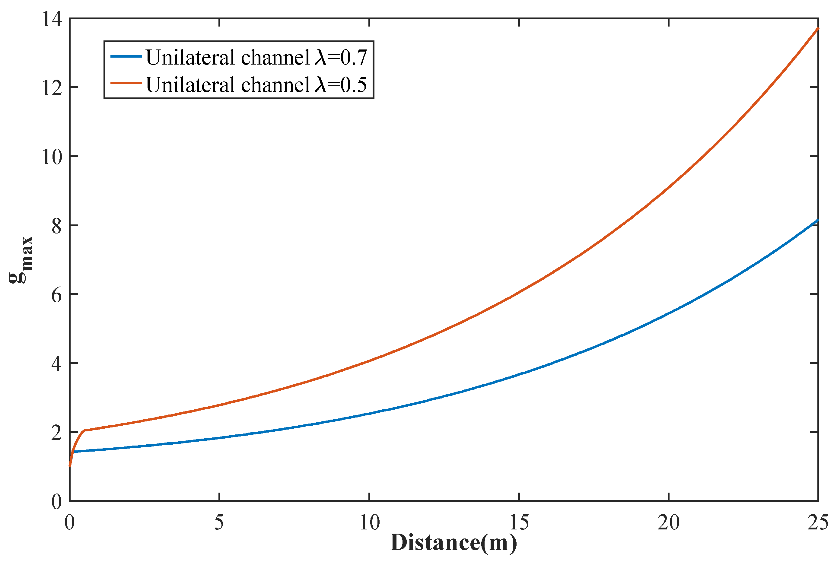
Here, we take the seawater attenuation coefficient and excess noise as fixed values (average seawater attenuation coefficient m, and the excess noise is 0.01 [26]) to illustrate the maximum achievable value of the NLA gain with the increase of propagation distance. As shown in Figure 4, the value of the maximum achievable gain coefficient increases with the increase of the transmission distance. In the case of the same seawater lossy channel, the larger the , the smaller the maximum gain coefficient. In practice, the maximum gain coefficient is available when the transmission distance is short, which provides a basis for selecting an appropriate gain coefficient to improve the performance of the system.
From Equation (5), we know the inherent parameters is acrucial factor affecting the fidelity. In the ideal channel ( and ), the fidelity increases monotonically with the compression parameters [41]. There is actually an optimal inherent parameters to maximize the fidelity of the lossy channel. For unilateral lossy channel, the optimal inherent parameters can be derived mathematically as
where is the optimal squeezing parameter of entanglement source. As shown in Figure 5, using NLA can improve the optimal inherent parameters , which means that we can try to use the switching gain to achieve the optimal inherent parameters under the fluctuating transmittance in the next work, thus improving the maximum fidelity.
4.2. Performance Improvement under Seawater Lossy Channel
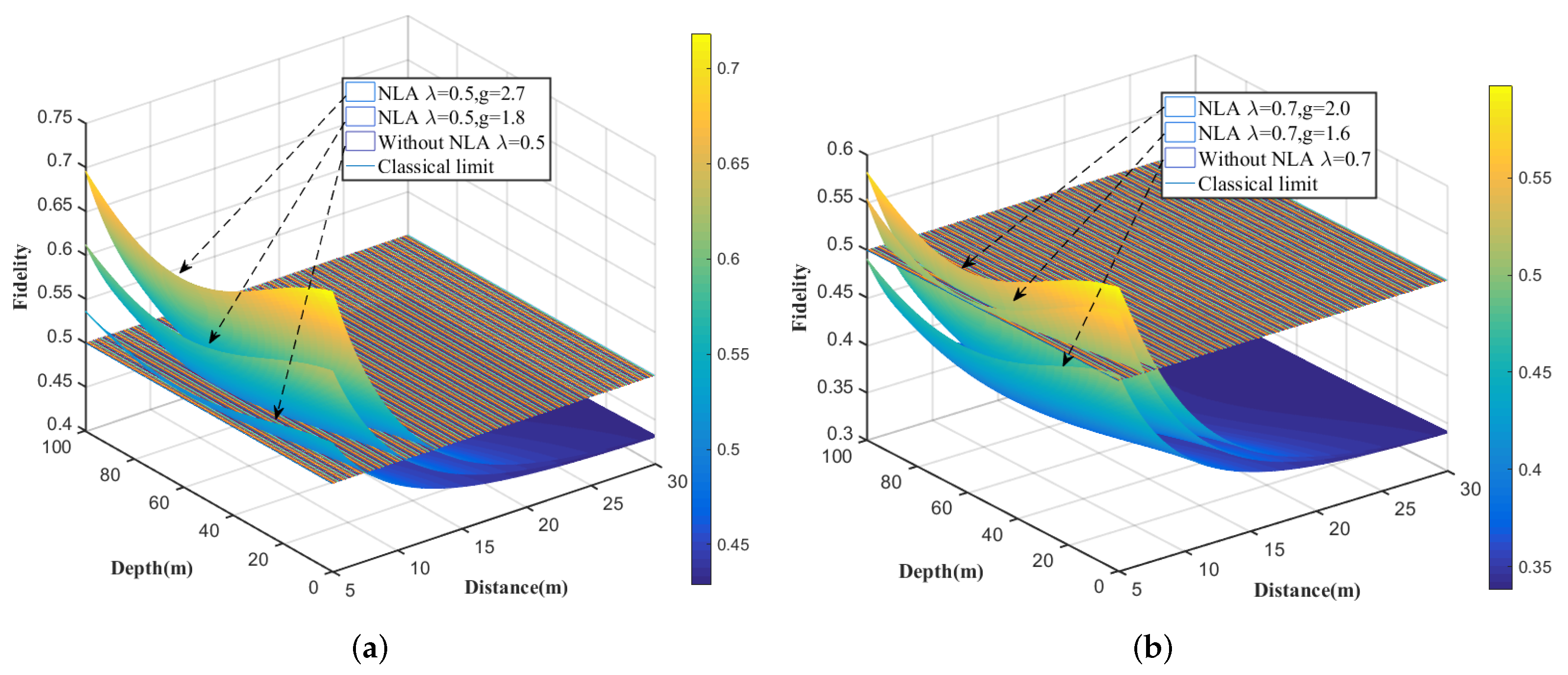
In Figure 6a,b, it demonstrate the performance improvement of the NLA-based CVQT under seawater channel, where the scheme with the tunable gain, the original scheme without NLA and the classical bound of coherent state of CVQT are shown in numerical simulations.
We find that the NLA-involved detection can improve the fidelity and maximum transmission distance of the system, and the improvement is obvious with the increase of the gain coefficient g. For example, reaches the classical boundary after propagating 9.4 m under the worst attenuation conditions (depth = 63.98 m). However, with the same attenuation conditions, propagates 5.6 m, which is 3.8 m less than that using NLA. Meanwhile, in the case of the worst attenuation conditions, is 0.125 higher than that (distance = 5 m).
For the given gain, the fidelity decreases with the increase of transmission distance, first decreases and then increases with the increase of depth, because the attenuation of seawater reaches its peak at 40–80 m. The performance improvement of NLA is affected by the entanglement source. For smaller , the improvement is greater. This is because smaller allows greater gain, and the greater gain of NLA, the more obvious channel loss compensation. However, the effect of NLA is probability success, and the probability of success is negatively correlated with the gain coefficient. Therefore, the selected gain coefficient should not be too large.
5. Conclusions
We have suggested an NLA-based approach for improving the performance of CVQT over seawater channel. Based on numerical analysis of the chlorophyll-a model and the discussion of background noise, we focused on the influence of parameters of lossy seawater channel on performance of the CVQT system in terms of fidelity and maximal transmission distance. Simulation analysis shows that the NLA-based scheme can compensate the influence of channel loss on the entanglement source and thus improve the performance of the system. It is found that the smaller entanglement source parameter and the larger transmission distance allow the grater gain coefficient of NLA. Taking into account the same channel loss, the larger the gain coefficient of NLA and the appropriate communication depth (<40 m or >80 m), which all give birth to the performance improvement of the CVQT system.
Author Contributions
Conceptualization, X.R. and Y.G.; methodology, H.W. and X.L.; formal analysis, X.R.; data curation, H.Z.; writing—original draft preparation, H.W.; writing—review and editing, X.L.; validation, Y.G. All authors have read and agree to the published version of the manuscript.
Funding
This work is supported by the National Natural Science Foundation of China (Grant No. 61871407), the Natural Science Foundation of Hunan Province (Grant No. 2021JJ30878), and the Special Funds for the Construction of an Innovative Province in Hunan (Grant No. 2020GK4063, 2022GK2016). We acknowledge the support from the Optoelectronic Information Center of Central South University and Hunan Railway Engineering Machinery Electro-hydraulic Control Engineering Technology Research Center.
Institutional Review Board Statement
Not applicable.
Informed Consent Statement
Not applicable.
Data Availability Statement
The data used are included in the article.
Conflicts of Interest
The authors declare no conflict of interest.
Appendix A. The Absorption Coefficient of the Seawater Channel
, the wavelength-dependent absorption coefficient of pure seawater, which can be found in [32].
, the absorption coefficient related to chlorophyll-a. is the spectral absorption coefficient of chlorophyll-a (with 400 nm as reference), is the function of chlorophyll-a concentration changing with depth d, which can be found in [33].
, represents the absorption coefficient of fulvic acid. and correspond to fulvic acid spectral absorption coefficient (with 400 nm as reference) and absorption slope coefficient, respectively. is the function of fulvic acid concentration changing with depth d.
, represents the absorption coefficient of humic acid. and correspond to humic acid spectral absorption coefficient (with 400 nm as reference) and absorption slope coefficient, respectively. is the function of humic acid concentration changing with depth d.
, represents the absorption coefficient of mineral and detritus. and are the the spectral absorption coefficient of mineral and detritus (with 400 nm as reference) and absorption slope coefficient, respectively.
The specific parameter values are shown in Table A1.

Table A1.
The parameters in absorption coefficient.
| Parameters | Value | Description |
|---|---|---|
| Fulvic acid spectral absorption coefficient | ||
| Fulvic acid absorption slope coefficient | ||
| Humic acid spectral absorption coefficient | ||
| Humic acid absorption slope coefficient | ||
| Mineral and detritus spectral absorption coefficient | ||
| Mineral and detritus absorption slope coefficient |
Appendix B. The Scattering Coefficient of the Seawater Channel
From Equation (7), the scattering coefficient consists of the following three parts, namely
, the wavelength-dependent scattering coefficient of pure seawater.
, represents the scattering coefficient of small particles. and correspond to small particles scattering spectrum and concentration function, respectively.
, represents the scattering coefficient of large particles. and correspond to large particles scattering spectrum and concentration function, respectively.
Table A2.
The calculation formulas for scattering coefficient.
| Function | Formula |
|---|---|
References
- Bennett, C.H.; Brassard, G.; Crépeau, C.; Jozsa, R.; Peres, A.; Wootters, W.K. Teleporting an unknown quantum state via dual classical and Einstein-Podolsky-Rosen channels. Phys. Rev. Lett. 1993, 70, 1895–1899. [Google Scholar] [CrossRef] [PubMed] [Green Version]
- Bouwmeester, D.; Pan, J.W.; Mattle, K.; Eibl, M.; Weinfurter, H.; Zeilinger, A. Experimental quantum teleportation. Nature 1997, 390, 575–579. [Google Scholar] [CrossRef] [Green Version]
- Hu, X.M.; Zhang, C.; Liu, B.H.; Cai, Y.; Ye, X.J.; Guo, Y.; Xing, W.B.; Huang, C.X.; Huang, Y.F.; Li, C.F.; et al. Experimental high-dimensional quantum teleportation. Phys. Rev. Lett. 2020, 125, 230501. [Google Scholar] [CrossRef] [PubMed]
- Marcikic, I.; De Riedmatten, H.; Tittel, W.; Zbinden, H.; Gisin, N. Long-distance teleportation of qubits at telecommunication wavelengths. Nature 2003, 421, 509–513. [Google Scholar] [CrossRef] [PubMed]
- Yin, J.; Ren, J.G.; Lu, H.; Cao, Y.; Yong, H.L.; Wu, Y.P.; Liu, C.; Liao, S.K.; Zhou, F.; Jiang, Y.; et al. Quantum teleportation and entanglement distribution over 100-kilometre free-space channels. Nature 2012, 488, 185–188. [Google Scholar] [CrossRef] [PubMed]
- Ren, J.G.; Xu, P.; Yong, H.L.; Zhang, L.; Liao, S.K.; Yin, J.; Liu, W.Y.; Cai, W.Q.; Yang, M.; Pan, J.W.; et al. Ground-to-satellite quantum teleportation. Nature 2017, 549, 70–73. [Google Scholar] [CrossRef] [Green Version]
- Braunstein, S.L.; Kimble, H.J. Teleportation of continuous quantum variables. Phys. Rev. Lett. 1998, 80, 869. [Google Scholar] [CrossRef] [Green Version]
- Lee, N.; Benichi, H.; Takeno, Y.; Takeda, S.; Webb, J.; Huntington, E.; Furusawa, A. Teleportation of nonclassical wave packets of light. Science 2011, 332, 330–333. [Google Scholar] [CrossRef] [Green Version]
- Huo, M.R.; Qin, J.L.; Cheng, J.L.; Yan, Z.H.; Qin, Z.Z.; Su, X.L.; Jia, X.J.; Xie, C.D.; Peng, K.C. Deterministic quantum teleportation through fiber channels. Sci. Adv. 2018, 4, eaas9401. [Google Scholar] [CrossRef] [Green Version]
- Rudolph, T.; Sanders, B.C. Requirement of optical coherence for continuous-variable quantum teleportation. Phys. Rev. Lett. 2001, 87, 077903. [Google Scholar] [CrossRef] [Green Version]
- Zhao, H.; Feng, J.X.; Sun, J.K.; Li, Y.J.; Zhang, K.S. Real time deterministic quantum teleportation over 10 km of single optical fiber channel. Opt. Express 2022, 30, 3770–3782. [Google Scholar] [CrossRef] [PubMed]
- Jin, X.M.; Ren, J.G.; Yang, B.; Yi, Z.H.; Zhou, F.; Xu, X.F.; Wang, S.K.; Yang, D.; Hu, Y.F.; Jiang, S.; et al. Experimental free-space quantum teleportation. Nat. Photon. 2010, 4, 376–381. [Google Scholar] [CrossRef]
- Zuo, Z.Y.; Wang, Y.J.; Liao, Q.; Guo, Y. Overcoming the uplink limit of satellite-based quantum communication with deterministic quantum teleportation. Phys. Rev. A 2021, 104, 022615. [Google Scholar] [CrossRef]
- Ma, X.S.; Kropatschek, S.; Naylor, W.; Scheidl, T.; Kofler, J.; Herbst, T.; Zeilinger, A.; Ursin, R. Experimental quantum teleportation over a high-loss free-space channel. Opt. Express 2012, 20, 23126–23137. [Google Scholar] [CrossRef] [Green Version]
- Zhang, Q.; Goebel, A.; Wagenknecht, C.; Chen, Y.A.; Zhao, B.; Yang, T.; Mair, A.; Schmiedmayer, J.; Pan, J.W. Experimental quantum teleportation of a two-qubit composite system. Nat. Phys. 2006, 2, 678–682. [Google Scholar] [CrossRef] [Green Version]
- Barasinski, A.; Cernoch, A.; Lemr, K. Demonstration of controlled quantum teleportation for discrete variables on linear optical devices. Pys. Rev. Lett. 2019, 122, 170501. [Google Scholar] [CrossRef]
- Rajiuddin, S.; Baishya, A.; Behera, B.K.; Panigrahi, P.K. Experimental realization of quantum teleportation of an arbitrary two-qubit state using a four-qubit cluster state. Quantum Inf. Process. 2020, 19, 87. [Google Scholar] [CrossRef]
- Chatterjee, Y.; Devrari, V.; Behera, B.K.; Panigrahi, P.K. Experimental realization of quantum teleportation using coined quantum walks. Quantum Inf. Process. 2020, 19, 31. [Google Scholar] [CrossRef] [Green Version]
- Simon, C. Towards a global quantum network. Nat. Photon. 2017, 11, 678–680. [Google Scholar] [CrossRef] [Green Version]
- Liao, Q.; Haijie, L.; Lingjin, Z.; Guo, Y. Quantum secret sharing using discretely modulated coherent states. Phys. Rev. A 2021, 103, 032410. [Google Scholar] [CrossRef]
- Ji, L.; Gao, J.; Yang, A.L.; Feng, Z.; Lin, X.F.; Li, Z.G.; Jin, X.M. Towards quantum communications in free-space seawater. Opt. Express 2017, 25, 19795–19806. [Google Scholar] [CrossRef] [PubMed] [Green Version]
- Hu, C.Q.; Yan, Z.Q.; Gao, J.; Jiao, Z.Q.; Li, Z.M.; Shen, W.G.; Chen, Y.; Ren, R.J.; Qiao, L.F.; Yang, A.L.; et al. Transmission of photonic polarization states through 55 m water: Towards air-to-sea quantum communication. Photon. Res. 2019, 7, A40–A44. [Google Scholar] [CrossRef]
- Haltrin, V.I. Chlorophyll-based model of seawater optical properties. Appl. Opt. 1999, 38, 6826–6832. [Google Scholar] [CrossRef] [PubMed] [Green Version]
- Gilerson, A.; Zhou, J.; Hlaing, S.; Ioannou, I.; Schalles, J.; Gross, B.; Moshary, F.; Ahmed, S. Fluorescence component in the reflectance spectra from coastal waters. Dependence on water composition. Opt. Express 2007, 15, 15702. [Google Scholar] [CrossRef]
- Gariano, J.; Djordjevic, I.B. Theoretical study of a submarine to submarine quantum key distribution systems. Opt. Express 2019, 27, 3055. [Google Scholar] [CrossRef]
- Guo, Y.; Xie, C.L.; Huang, P.; Li, J.W.; Zhang, L.; Huang, D.; Zeng, G.H. Channel-parameter estimation for satellite-to-submarine continuous-variable quantum key distribution. Phys. Rev. A 2018, 97, 052326. [Google Scholar] [CrossRef]
- Liao, Q.; Xiao, G.; Xu, C.; Xu, Y.; Guo, Y. Discretely modulated continuous-variable quantum key distribution with untrusted entanglement source. Phys. Rev. A 2020, 102, 032604. [Google Scholar] [CrossRef]
- Braunstein, S.L.; Fuchs, C.A.; Kimble, H.J. Criteria for continuous-variable quantum teleportation. J. Mod. Opt. 2000, 47, 267–278. [Google Scholar] [CrossRef]
- Weedbrook, C.; Pirandola, S.; Garcia-Patron, R.; Cerf, N.J.; Ralph, T.C.; Shapiro, J.H.; Lloyd, S. Gaussian quantum information. Rev. Mod. Phys. 2012, 84, 621–669. [Google Scholar] [CrossRef]
- Chizhov, A.V.; Knoll, L.; Welsch, D.G. Continuous-variable quantum teleportation through lossy channels. Rev. Mod. Phys. 2002, 65, 022310. [Google Scholar] [CrossRef] [Green Version]
- Feng, Z.; Li, S.B.; Xu, Z.Y. Experimental underwater quantum key distribution. Opt. Express 2021, 29, 8725–8736. [Google Scholar] [CrossRef] [PubMed]
- Prieur, L.; Sathyendranath, S. An optical classification of coastal and oceanic waters based on the specific spectral absorption curves of phytoplankton pigments, dissolved organic matter, and other particulate materials. J. Geophys. Res. 1981, 26, 671. [Google Scholar] [CrossRef]
- Uitz, J.; Claustre, H.; Morel, A.; Hooker, S.B. Vertical distribution of phytoplankton communities in open ocean: An assessment based on surface chlorophyll. J. Geophys. Res.-Oceans 2006, 111, C08005. [Google Scholar] [CrossRef]
- Ruan, X.C.; Zhang, H.; Zhao, W.; Wang, X.X.; Li, X.; Guo, Y. Security analysis of discrete modulated continuous-variable quantum key distribution over seawater channel. Appl. Sci. 2019, 9, 4956. [Google Scholar] [CrossRef] [Green Version]
- Huang, D.; Huang, P.; Lin, D.K.; Zeng, G.H. Long-distance continuous-variable quantum key distribution by controlling excess noise. Sci. Rep. 2016, 6, 19201. [Google Scholar] [CrossRef] [PubMed] [Green Version]
- Jaruwatanadilok, S. Underwater wireless optical communication channel modeling and performance evaluation using vector radiative transfer theory. IEEE J. Sel. Areas Commun. 2008, 26, 1620–1627. [Google Scholar] [CrossRef]
- Miao, E.L.; Han, Z.F.; Gong, S.S.; Zhang, T.; Diao, D.S.; Guo, G.C. Background noise of satellite-to-ground quantum key distribution. New J. Phys. 2005, 7, 215. [Google Scholar]
- Blandino, R.; Leverrier, A.; Barbieri, M.; Etesse, J.; Grangier, P.; Tualle-Brouri, R. Improving the maximum transmission distance of continuous-variable quantum key distribution using a noiseless amplifier. Phys. Rev. A 2012, 86, 012327. [Google Scholar] [CrossRef] [Green Version]
- Xu, B.J.; Tang, C.M.; Chen, H.; Zhang, W.Z.; Zhu, F.C. Improving the maximum transmission distance of four-state continuous-variable quantum key distribution by using a noiseless linear amplifier. Phys. Rev. A 2013, 87, 062311. [Google Scholar] [CrossRef] [Green Version]
- Zhang, Y.C.; Li, Z.Y.; Weedbrook, C.; Marshall, K.; Pirandola, S.; Yu, S.; Guo, H. Noiseless linear amplifiers in entanglement-based continuous-variable quantum key distribution. Entropy 2015, 17, 4547–4562. [Google Scholar] [CrossRef] [Green Version]
- Hofmann, K.; Semenov, A.A.; Vogel, W.; Bohmann, M. Quantum teleportation through atmospheric channels. Phys. Scr. 2019, 94, 125104. [Google Scholar] [CrossRef] [Green Version]
Figure 1.
(Color online) EB version of the NLA-CVQT, where the EPR state is prepared by Alice and is transmitted to Bob through the seawater lossy channel. At the receiver, Bob use noiseless linear amplifiers for performance improvement. LO, local oscillator; BS, beam splitter; , gain of NLA.
Figure 1.
(Color online) EB version of the NLA-CVQT, where the EPR state is prepared by Alice and is transmitted to Bob through the seawater lossy channel. At the receiver, Bob use noiseless linear amplifiers for performance improvement. LO, local oscillator; BS, beam splitter; , gain of NLA.

Figure 2.
(Color online) (a) The functional relationship between absorption coefficient , depth d, wavelength . (b) The functional relationship between scattering coefficient , depth d, wavelength . (c) The functional relationship between total channel attenuation , depth d, wavelength . (d) The functional relationship between transmittance , depth d, transmission distance L. Here, the variation of absorption coefficient , scattering coefficient , total attenuation coefficient and transmittance are characterized by the change of color, the unit of , , are m.

Figure 3.
Attenuation curve of background light noise with seawater depth.

Figure 4.
Variation of achievable NLA gain coefficient with transmission distance in seawater lossy channel.
Figure 4.
Variation of achievable NLA gain coefficient with transmission distance in seawater lossy channel.

Figure 5.
Optimal inherent parameters as a function of transmission distance and depth in the case of a lossy channel. Here, the NLA gain coefficient .
Figure 5.
Optimal inherent parameters as a function of transmission distance and depth in the case of a lossy channel. Here, the NLA gain coefficient .

Figure 6.
(Color online) Fidelity as a function of transmission distance and depth in the case of a lossy channel (a) EPR state parameter = 0.5, NLA gain coefficient . (b) EPR state parameter = 0.7, NLA gain coefficient .
Figure 6.
(Color online) Fidelity as a function of transmission distance and depth in the case of a lossy channel (a) EPR state parameter = 0.5, NLA gain coefficient . (b) EPR state parameter = 0.7, NLA gain coefficient .

Publisher’s Note: MDPI stays neutral with regard to jurisdictional claims in published maps and institutional affiliations. |
© 2022 by the authors. Licensee MDPI, Basel, Switzerland. This article is an open access article distributed under the terms and conditions of the Creative Commons Attribution (CC BY) license (https://creativecommons.org/licenses/by/4.0/).
Share and Cite
MDPI and ACS Style
Wu, H.; Liu, X.; Zhang, H.; Ruan, X.; Guo, Y. Performance Analysis of Continuous Variable Quantum Teleportation with Noiseless Linear Amplifier in Seawater Channel. Symmetry 2022, 14, 997. https://0-doi-org.brum.beds.ac.uk/10.3390/sym14050997
AMA Style
Wu H, Liu X, Zhang H, Ruan X, Guo Y. Performance Analysis of Continuous Variable Quantum Teleportation with Noiseless Linear Amplifier in Seawater Channel. Symmetry. 2022; 14(5):997. https://0-doi-org.brum.beds.ac.uk/10.3390/sym14050997
Chicago/Turabian StyleWu, Hao, Xu Liu, Hang Zhang, Xinchao Ruan, and Ying Guo. 2022. "Performance Analysis of Continuous Variable Quantum Teleportation with Noiseless Linear Amplifier in Seawater Channel" Symmetry 14, no. 5: 997. https://0-doi-org.brum.beds.ac.uk/10.3390/sym14050997
Note that from the first issue of 2016, this journal uses article numbers instead of page numbers. See further details here.