Jigging: A Review of Fundamentals and Future Directions


Mineral Processing Laboratory, Federal University of Rio Grande do Sul, 9500 Bento Gonçalves Avenue, Porto Alegre 91501-970, Brazil
Minerals 2020, 10(11), 998; https://0-doi-org.brum.beds.ac.uk/10.3390/min10110998
Submission received: 19 October 2020
/
Revised: 4 November 2020
/
Accepted: 9 November 2020
/
Published: 10 November 2020
(This article belongs to the Special Issue Gravity Concentration)
Abstract
:For centuries, jigging has been a workhorse of the mineral processing industry. Recently, it has also found its way into the recycling industry, and the increasing concerns related to water usage has led to a renewed interest in dry jigging. However, the current scenario of increasing ore complexity and the advent of smart sensor technologies, such as sensor-based sorting (SBS), has established increasingly challenging levels for traditional concentration methods, such as jigging. Against this background, the current review attempts to summarize and refresh the key aspects and concepts about jigging available in the literature. The configuration, operational features, applications, types, and theoretical models of jigging are comprehensively reviewed. Three promising paths for future research are presented: (1) using and adapting concepts from granular physics in fundamental studies about the stratification phenomena in jigs; (2) implementing advanced control functions by using machine vision and multivariate data analysis and; (3) further studies to unlock the potential of dry jigs. Pursuing these and other innovations are becoming increasingly essential to keep the role of jigging as a valuable tool in future industry.
1. Introduction
Jigging is one of the oldest methods of ore treatment and remains one of the workhorses of the mining industry. Until recently, it was, together with dense medium separation (DMS), the main (when not the only) choice for pre-concentration and concentration of coarse-sized ores and coals. Jigging has also currently exceeded the limits of mineral processing, having found applications in different recycling industries, and growing concern related to water usage has led to a renewed interest in the use of dry jigging.
On the other hand, the current scenario of decreasing ore grades and the recent developments in sensor-based sorting (SBS) technologies have established increasingly challenging levels of operational efficiency. With compact installation units, dry operation, and the ability to deal with ores of complex mineralogy, like rare earth bearing minerals [1], SBS technology has the potential to replace jigs in many of its traditional applications, particularly those involving coarse particle treatment. The scenario is in some ways analogous to the beginning of the 20th century when the advent of magnetic separation and froth flotation partially replaced gravity concentration processes. Breakthroughs and innovations in the understanding, design, and optimization of jigs should be sought in order to keep the technique competitive.
The present paper provides an up to date review of the fundamentals of jigging operation and outlines some avenues for future research and developments. The configuration, operational principles, and main applications of different jig types have been comprehensively reviewed. A description of the main theoretical approaches used is presented, highlighting their strengths and weaknesses. Finally, suggestions for upgrading jigging technology through new conceptual approaches are made.
Paper Structure
Although the current paper does not consist of a systematic review, some ordinary criteria were considered when gathering and evaluating the available literature. Many of the referenced articles have been obtained after an extensive search in the databases Scopus®, Web of Science®, and Google Scholar® by using the keywords “jigging” or “jig”. Some publications, especially older textbooks and proceedings, were available only in their print versions. The majority of the literature covered is in English, with some few exceptions.
The paper is structured as follows: Section 1 outlines the purpose of the review and describes its structure and approach. Section 2 provides a comprehensive overview of jigging principles, basic configurations, types, and applications; in this section, by considering the previous review by Lyman [2] as a landmark, preference has been given to data published in the last three decades. Section 3 reviews the main theoretical approaches used to describe the complex mechanisms of pulsation and stratification in jigs; purely empirical models, such as statistical models, have not been included here. Section 4 discusses the various operational aspects affecting jigging. In Section 5, some research gaps, potential upgrades, and new conceptual frameworks are identified and discussed. Finally, Section 6 synthesizes the main conclusions and future possibilities.
2. Jigging: Concepts and Development
Gravity concentration methods aim to create conditions in which particles of different densities, sizes, and shapes may move relative to each other when under the action of gravity or centrifugal forces, originating multiple bands containing the light and dense materials [3,4]. When the relative interparticle movement manifests itself in the form of vertical expansions and contractions of a particle bed caused by a pulsing fluid, the gravity concentration operation in question is known as jigging. Although its origin possibly dates back as far as Classical Antiquity [2,5], the first remarkable description of jigging appeared only in the 16th century in De Re Metallica, the well-known seminal work by Agricola [6]. In this, the first jigs are depicted as perforated baskets (the “jigging sieve”) containing the mixed ores that were manually and repeatedly dipped into a water tank, after which stratified layers of ore were removed by hand. Until the advent of the industrial revolution, modifications in jigging devices were limited to a little more than the inclusion of levers for using larger baskets [7]. The emergence of hydraulic systems like the piston pump and the plunger pump, with or without seals, are regarded as decisive for the introduction of mechanically pulsated jigs [3], giving rise to the basic configuration of modern jigs.
2.1. Hydraulic Jigs—Configuration and Types
In modern water jigs, the original basket was replaced by a compartmentalized vessel equipped with a sieve (or screen) to support the particle bed, mechanical pulsation devices were introduced, and operation became continuous. The general scheme of most industrial jigs consists of a container divided into two compartments, one of them corresponding to the separation chamber where feed particles are located on a supporting sieve and through which the water performs its oscillatory motion. The other compartment contains the mechanism that drives fluid pulsation responsible for moving the bed during its passage by the jig (Figure 1). The pulse wave can be produced either mechanically through a plunger or by the pulsation of water or air that is intermittently fed into the jig vessel by using a special valve. In some types of jig, the relative motion between particles and water is obtained through the vertical displacement of the supporting sieve.
In the case of continuous operation, particles of varied composition (like non-beneficiated ores) are fed at one end of the jig tank and distributed over the screen, which is slightly inclined towards the outlet end (see Figure 2). As particles pass through the equipment, they are subject to successive cycles of expansion and compaction that promote the stratification action. When reaching the discharge end, the particle bed must be separated into two distinct zones: a layer of light material, located in the upper portion of the bed; and a layer of dense particles concentrated in the lower fraction. The target content and yield of the desired product will define the height (“cut point” or “cut height”) in which the stratified bed should be split at the discharge end. In hydraulic jigs, most of the water is withdrawn from the jig with the products, so that replacement water (“hutch water”) is regularly pumped into the jig vessel.
The differences among the various types of industrial jig are associated with a plethora of factors, including vessel geometry, pulsation mechanism, bed transport, discharge system, and separation control scheme. In this sense, Sampaio and Tavares [8] have proposed a broad classification of jigging devices based on three main aspects: (a) condition of the jig sieve (fixed or mobile), (b) method of extraction of the heavy product, and (c) bed pulsation mechanism.
In the most common fixed-sieve jigs, the water moves through a sieve that remains immobile inside the separation chamber, as previously mentioned. In some jigs, however, the bed motion is produced through the mechanical displacement of the jig sieve within a stationary fluid. Versions of this type of jig were developed in the 19th century, as exemplified by the already obsolete Hancock and James jigs [9]. Current jig models in this category include the ROMJIG [10] and the InLine Pressure Jig [11]. In both, the jig screen is cyclically moved up and down by a hydraulic servo system connected to the screen.
While the light product is invariably removed by overflowing, the dense product leaves the jig in two distinct manners: “through the screen” and “over the screen”. In the first case, used for finer-sized feeds, heavier particles pass through the screen to be drawn off as the dense product, collected into the bottom of the jig compartment and removed through a spigot. In these jigs, a layer of heavy, coarse material (called “ragging”) is placed on the screen onto which the feed is introduced. Thus only particles of high density can penetrate through the ragging and then reach the jig screen.
When jigging “over the screen” is used, a discharge device equipped with sensor systems controls the withdrawal of the heavy product. The most utilized methods of discharge include the regulation of opening of a mobile gate or the adjustment of the rotation speed of a rotary discharge valve. In order to maintain an accurate cut-point, the thickness of the heavy material layer is continuously measured by sensors, and the immersed float method is still used. In this, a float calibrated with weights to exhibit an apparent density equal to the separation density is used to adjust the height in which the bed will be split [2]. Electromagnetic or ultrasonic displacement sensors measure the position of the float, which is the input of proportional–integral–derivative PID controllers that drive the discharge device. Floats are eventually subject to inaccuracies due to their invasive nature and the harsh environment inside a jig bed. Radiometric density sensors have been pointed out as a more accurate option by allowing tracking changes in density over the bed pulsation cycle and have been recently used to validate a dynamic model of discharge in a coal jig [12].
Jigs can also be divided concerning the pulse generation mechanism into piston-type jigs, diaphragm-type jigs, air-pulsated jigs, and mobile-sieve jigs (described above). One of the first mechanical jigs is the Harz jig [3]. This consists of a two-chamber tank, as illustrated in Figure 1, equipped with a piston linked to a connecting rod and crank system, thus resulting in a harmonic movement. Although it has simple mechanical design and operation, water leakage is a recurring concern when operating this jig due to the difficulty of maintaining the seal between the piston and the housing walls.
A solution to prevent water leakage through the flanks of the plunger is to replace the piston with a rubber diaphragm connected to an eccentric vertical shaft, such as in the Denver jig [4]. With a layout nearly similar to the Harz jig, the Denver jig has a rotary valve operating in synchrony with the plunger, which avoids the input of hutch water during the suction stroke and allows more precise control of the jigging cycle. Variations in tank design and the position of the plunger in the chamber have originated many other models of diaphragm-pulsated jigs, such as the Bendelari jig, the Pan-American jig, and the Yuba jig [8]. Figure 3 depicts a basic scheme of these types of equipment.
The use of compressed air instead of mechanical devices for pulsating the jig water appeared at the end of the 19th century with the development of the Baum jig [13]. Since then, air-pulsated jigs have been universally applied in mineral processing, especially coal beneficiation, due to their high capacity and versatility compared to the piston and diaphragm-type jigs [14]. The decisive factor for the success of air-pulsated jigs is the use of electronically controlled air valves of quick actuation for controlling the water movement, thus allowing a wide variation of the pulse shape. The Baum jig works by forcing air under pressure (up to 17 kPa) into an air chamber located on one side of a U-shaped jig vessel (similar to that displayed in Figure 1) to pulsate the jig water [15]. Electrically driven rotary-piston valves control the timing of air admission and exhaustion inside the jig chamber, allowing precise control of pulse duration and intensity. When combined with automatic control systems of discharge of the heavy product, Baum jigs results in a more flexible and robust option in comparison to mechanically pulsated jigs.
To maintain a uniform distribution of water velocity across the bed is one major difficulty of side-pulsed jigs like the Baum jig, which in turn limits the jig bed width (and so feed capacity). Thus, the TACUB and then the BATAC jigs addressed this limitation by using multiple air chambers positioned under the jig sieve equipped with individual electronic valves for controlling air input and exhaust [16]. This new design provided a more uniform flow across the bed, enabling the construction of larger jigs (up to 7 m wide along) able to achieve high separation densities [10]. Some BATAC and Baum jigs have the longitudinal section of the vessel segmented into multiple compartments, each one having independent control of the pulsating wave. For practical purposes, such equipment can be considered as the conjugation of numerous jigs in series operation.
Table 1 summarizes the classification of different jigs according to the criteria mentioned previously. It is worth noting that some types of jig, particularly diaphragm-pulsated types, are more likely to be used for ores, in which the target is the denser constituent. The contrary occurs for coal, in which other pulsating mechanisms and the “over the screen” discharge are most common. Also, the operating flexibility of air-pulsated jigs makes them applicable for different uses. A more detailed discussion about jigging applications is found in Section 2.3.
2.2. Alternative Jigs
A few separators have been developed or adapted using the basic principle of jigging, i.e., bed stratification induced by fluid pulses, although one or more design and operating features may significantly differ from those of conventional hydraulic jigs. The most distinguishing equipment in this class includes dry jigs, centrifugal jigs, and a range of jigging machines exclusively developed for plastics recycling.
2.2.1. Dry Jigs
Dry jigging (also called “pneumatic” or “air jigging”, though these designations may be mistaken as air-pulsated water jigs) is becoming more and more relevant as the concern with slurry waste disposal and water handling costs intensifies. Dry jigging was introduced in the coal industry during the 1920s by applying the concepts involved in wet jigging technology to the design of pneumatic cleaning machines [17]. Since then, significant improvements have been implemented in its conception and operation.
Modern dry jigs consist of an inclined vibrating deck in which the feed distributed at one end is subjected to the action of two distinct upward air streams (see Figure 4). One of them is continuous, having the function to loosen the bed and so allow a uniform air distribution. A second superimposed pulsed airflow promotes density stratification of the bed during its passage on the jig deck. The combined effect of the two independent air streams allows precise control of stroke frequency and amplitude [18]. Nuclear density sensors are installed near the discharge end of the deck to control the bed level and the cut-height [19]. Stargate discharge valves are normally used for the withdrawal of the products. The equipment is enclosed and a dust collector system handles the generated dust.
The evident advantage of dry jigging is its complete elimination of process water, which is particularly desirable in places with limited or difficult access to water or if the jig feed is affected by moisture. However, its separation efficiency is recognizably lower than that of hydraulic jigs since the density of air is negligible compared to the density of water. Such low density is compensated for by using high air stream velocities, thus increasing turbulence and remixing effects. Consequently, dry jigs are applied to separate only close-sized material, normally larger than 2 mm [20], containing relatively low content of near-gravity material (NGM).
2.2.2. Centrifugal Jigs
In centrifugal jigs, the jig screen consists of a rotating cylinder in which centrifugal forces dozens of times higher than gravity are produced. Therefore, it is classified as one of the so-called “enhanced gravity concentrators” or simply centrifugal concentrators, which also include the Knelson, the Falcon, and the multi-gravity concentrators [4]. Currently, there exist two commercial models of centrifugal jigs: the Kelsey jig [21] and the Altair jig [22]. In both versions, the rotating bowl is placed vertically inside a casing having launders to collect the concentrate and tailings. The jig hutch is enclosed and equipped with a side-pulsed mechanism consisting of rubber diaphragms linked to pulse arms. During operation, feed slurry enters the jig through a pipe near the middle of the bowl and is distributed onto the jig screen by the action of centrifugal forces. The screen is covered with a layer of coarse heavy material (ragging) so that the discharge of the heavy product is of “through the screen” type. Pressurized water is periodically injected to keep the bed dilated as well as to ensure that only fine, dense particles can pass through the ragging. Low-density particles move upwardly onto the screen and are withdrawal over the bowl top.
The ability to greatly increase the apparent gravitational field allows centrifugal jigs to separate ultrafine particles (<40 μm), far below the minimum size limit of any other jig [21]. However, special attention must be paid to feed classification to avoid blockage of the jig screen by excessively coarse particles. Centrifugal jigs also figure among the gravity concentrators having the largest specific water consumption (up to 15 m3/ton of ore) [8].
2.2.3. Jigs for Plastic–Plastic Separation
In recent years, the growth in the application of jigging for solid wastes recycling has driven the conception of some unique jig separators. One such case is the set of jig prototypes developed exclusively for separating plastics. The first of these prototypes was the RETAC jig, a modified TACUB jig in which water pulsation and jigging cycle were optimized to address the difficulties related to the separation of materials with densities close to that of water, like plastics [23,24]. A further development consisted of installing an aeration diffusion tube (air bubbler) under the jig screen of a RETAC jig, giving rise to the so-called hybrid jig [25]. This equipment allowed the separation of plastics having similar densities but different surface wettability after a pretreatment step. The issue of separating plastics lighter than water was settled by conceiving of the Reverse jig prototype [26]. In this, a second screen installed at the top of the RETAC jig container allows separating plastics based on differences in levitation velocity. Improvements in the scheme of product extraction were subsequently made for the RETAC [27] and hybrid [28] jigs. Recently, the separation of metal wires and plastics was tested with relative success in the RETAC jig [29]. Although tailored to the recycling context, undiscovered benefits could result from the adaptation of some concepts involved in the design and operation of such jigs to the framework of mineral processing (e.g., the use of under-screen aeration to change the apparent density of particles, as in the hybrid jig).
2.3. Applications
The various types of hydraulic jig find vast application in mineral processing, ranging from minerals as dense as native gold (19 g/cm3) to vitrinite (up to 1.3 g/cm3) [8]. It is par excellence a traditional item in coal processing plants [30,31,32] while typical examples of using jigging for ore processing include beneficiation of iron ore [33,34,35], alluvial gold concentration [36], beneficiation of chalcedonite [37], pre-concentration of tungsten ores [38], cleaning of phosphate ores [39], as well as the concentration of tin and copper ores [4]. Dry jigs, otherwise, are mostly used in coal processing [40,41,42].
In recent decades, jigging has surpassed the limits of mineral processing, being currently utilized in a variety of sectors. As noticed by Turner [43], jigs have found applications as peculiar as in the separation of bones and cartilages for chewing gum production. Most notably, jigging has found particularly fertile ground in recycling and waste processing. As mentioned earlier, recycling of plastics like polyethylene, polycarbonate, and polyvinyl chloride PVC has even been boosting the development of new jigging devices, particularly in Japan [25,27,28]. In the case of metals recycling, jigging has been used to recover ferrous and non-ferrous metals from different sources, such as automobile scrap [44,45], steelmaking slag [46], and electric cable wastes [47].
Dry jigs, in particular, have been described as a promising method for recycling and upgrading the quality of coarse aggregates from construction and demolition wastes (CDW) [48,49]. The results obtained by Sampaio et al. [20] showed it to be possible to obtain recycled aggregates of composition that meet the minimum standards of quality of many countries. On the other hand, dry jigs showed a relatively high unit energy consumption (of the same order of crushers) in the economic analysis of a CDW plant performed by Coelho and Brito [50].
3. Theoretical Concepts of Jigging
As previously presented, the jigging process involves the stratification of a particle bed through pulsations generated by a fluid. Thus, two interdependent physical phenomena coexist in a jig: the repeated dispersion of the bed caused by the pulse strokes, and the stratification resulting from the differential relative motion of particles through the dispersed bed. Understanding bed dispersion during jig pulsation is a precondition for determining the way the particles may segregate. Ultimately, modeling bed dispersion allows determination of the incremental variation of bed porosity, which is decisive to numerical simulations of stratification in jigs. Two main theoretical approaches have been used to date for describing the mechanisms underlying particle stratification in jigs. The fluid-dynamic approach, based on the analysis of forces acting on individual particles during jigging, having its ultimate expression in the advanced Computational Fluid Dynamic-Discrete Element Method CFD-DEM coupled models; and the thermodynamic approach, which considers the lowering in potential energy of the bed as the true driving force behind stratification. The development of each of these concepts is presented in detail.
3.1. Bed Movement
The process of particle segregation in jigs is, by definition, linked to the vertical oscillatory motion of the jigging bed caused by the pulsation strokes. Some authors have found it appropriate to consider jigging as a process of repeated fluidization and de-fluidization of a bed in which the upward fluid velocity continuously varies along the operating cycle [51,52]. Therefore, similar to what occurs in fluidized beds, the upward fluid velocity (water or air, the last in the case of dry jigging) must reach a minimum threshold to enable the elevation of the jigging bed. This minimum velocity is a function of the flow regime and the pressure drop caused by the passage of the fluid through the particle bed. The first can be obtained from the Reynolds number for packed beds [53]:
where , , and μ are the superficial velocity, the density, and the viscosity of the fluid, respectively; is the bed porosity, and is the average diameter of the bed particles, for the case of spherical particles. Equation (1) is valid for fluid flow through the jig bed at rest only (before fluidization). For Re < 10, the flow is laminar and the pressure drop of the fluid can be predicted using the Carman–Kozeny equation:
where is the bed thickness. The minimum fluidization velocity occurs when the drag force (represented by the pressure drop) is equal to the apparent weight of the bed:
in which and are the densities of the bed-forming solid and the fluid medium, respectively, and is the acceleration of gravity (g = 9.81 m/s2). The expression contained on the right side of the equation represents the apparent force-weight per unit area of the bed (kN/m2). By replacing Equation (3) in Equation (2) for the minimum fluidization velocity, the following is obtained:
Correlations for the case of non-laminar flow regime, such as the Ergun correlation, can be found in the specialized literature [53]. A close observation of Equation. (4) reveals that the minimum fluid flow required to raise the bed (Qmín = Uf,mín x A, where A is the cross-sectional area of the jig bed) decreases as the density and viscosity of the medium increases. Since liquids are considerably denser and more viscous than gases under the same conditions, it is expected the upward fluid flow used to raise the bed will be much lower in hydraulic jigs than those used in dry jigging. Similarly, Uf,mín varies with the square of the average diameter of the bed-forming particles. As discussed later, both factors have an important limiting effect on the maximum particle size range of the jig feed, particularly for the case of dry jigging. Bed elevation constitutes only one of the phases of particle motion during jigging. Due to the cyclic pulsating stroke, the jigging bed describes an oscillatory movement characterized by pulses of amplitude A and frequency f (pulses or cycles per minute). A jigging cycle can be defined based on how the bed moves when subjected to pulses of amplitude A and frequency f. Figure 5 illustrates the bed and fluid displacement patterns for the simplest jigging cycle, a sinusoidal harmonic vertical motion, characteristic of piston-type jigs [3,8], that can be described by the following equation:
where is the superficial velocity of water and is the maximum velocity.
An extensive analysis of the bed motion during jigging was performed by Kirchberg and Hentzschel [51], who used a diaphragm jig with harmonic pulsations containing a bed of spherical particles, widely varying bed properties and pulsation conditions. Initially, the basic bed displacement was carefully recorded for the simplest possible case, i.e., for a bed formed by particles of the same composition and uniform size (Figure 6).
In the beginning, the bed is at rest and the velocity of the pulsating water is zero (A). Then, just after the upward flow starts, the drag force exerted by the fluid equals the apparent weight of the bed, raising it as a rigid body (A to B). Soon after, a high porosity zone is formed below the bed as the particles start settling (B to C). As the upward water flow passes through the bed, the bed porosity increases when a dispersion wave propagates from the base of the bed. As the fluid flow approaches its maximum value, the dispersion layer expands to a point where it covers the entire bed volume (C to D). As the upward water velocity decreases, conditions for sedimentation of the particles begin to prevail as the dispersion wave dissipates through the bed (D to E). Finally, the bed is once again static on the jig sieve while the suction phase begins.
Later studies, such as those of Kawashima et al. [54], Jinnouchi et al. [55], and Rong and Lyman [56], recognized that the porosity of the jigging bed (or, more precisely, the loosening of the bed) is a key parameter for describing stratification during jigging. In this sense, the work of Witteveen [57] provided great insights by modeling the porosity distribution as a function of time and height in a jig bed composed of uniform particles (same density, shape and size). Two of its interesting findings include: (a) loosening of the bed takes place during both parts of the stroke (upward and downward), and (b) the higher the position of the particle in the bed, the shorter the time it remains fluidized. More recent studies, such as those conducted by Xia et al. [58] and Viduka et al. [59], have applied the principles of computational fluid dynamics (CFD) to calculate the fluid motion during pulsation by directly solving the Navier–Stokes equations. The fluid flow and porosity distribution can thus be simulated in detail, allowing the capture of detailed features of the bed motion.
3.2. Stratification: Fluid-Dynamic Approach
The essence of fluid-dynamic models lies in the balance of forces acting on a single particle in an infinite fluid medium (Figure 7a). For the case of unidimensional vertical motion, the particle displacement relative to the fluid is driven by the gravitational force. The buoyancy force and especially the drag force are the main forces resisting the particle’s motion. The centrifugal force also plays a key role in the case of centrifugal jigs [8], but this specific case will not be considered here.
The magnitude and direction of particle motion result from the balance between the forces acting on it, given by [60]:
where and are the particle mass and velocity and , , and are the drag force, the buoyancy force and the gravity force, respectively. The combined effect of the later results in the apparent weight force:
where is the volume of the particle and equal to for a spherical particle. Unlike dense medium separation, in jigging the particles are denser than the working fluid (i.e., ρs > ρf) for the vast majority of cases, being the main exception the use of reverse jigging for plastic separation [26]. The drag force exerted on the particle depends on several factors, including its size, shape, inclination, as well as the flow conditions. All these elements are embodied in a drag coefficient, , from which the drag force can be determined according to the expression:
where is the surface area of a sphere.
Figure 7.
(a) Forces acting on a spherical particle in a fluid; (b) drag curve for motion of a sphere in a fluid. The curve was plotted based on the model of Haider and Levenspiel [61], see Equation (9).
Figure 7.
(a) Forces acting on a spherical particle in a fluid; (b) drag curve for motion of a sphere in a fluid. The curve was plotted based on the model of Haider and Levenspiel [61], see Equation (9).

The drag coefficient is related to the Reynolds number, , which represents the ratio of inertial forces to viscous forces within the medium, in the form of standard drag curves, as illustrated in Figure 7b. Four zones are identified according to the flow regime [53,60]: the so-called Stokes’ law region (Re < 0.3), where viscous forces are largely dominant; Newton’s law zone (500 < Re < 2 x 10⁵) in which inertial forces are predominant; an intermediary region between the Stokes and Newton regions (0.3 < Re < 500); and a turbulent region (Re > 2 x 10⁵) in which the domain of inertial forces is such that the flow becomes unstable and phenomena like boundary layer detachment take place. The most common jigging conditions occur in the intermediate and Newton flow regime [8]. The determination of in the intermediary region is usually undertaken by empirical correlation since there is no analytical solution of the Navier–Stokes equations in this range. Some correlations have been proposed for the entire range of Re, such as that of Haider and Levenspiel [61]:
which was the expression used to plot the curve shown in Figure 7b.
A condition of interest occurs when the particle acceleration is zero ( = 0 in Equation (6)) and a force balance is achieved so that the relative velocity of the particle is maximum. This velocity is known as the terminal velocity. By substituting Equations (7) and (8) in Equation (6), rearranging the terms, and considering Newton’s law region, the terminal velocity is expressed as follows:
Equation (10) reveals that the terminal velocity depends on the particle size and density as well as the density of the fluid medium. To evaluate the influence of each of these quantities, Rittinger [62] considered the situation of a binary mixture composed of spherical particles of a light material, with diameter and density , with a dense material with diameter and density . The condition in which both particles have the same terminal velocity is given by:
which after a rearranging gives:
Equation (12) indicates the settling ratio [62] between the sizes of particles of different densities that have the same terminal velocity. This ratio is valid for all flow regimes, being represented by the quotient q, where q = ½ for the Stoke’s regime, q = 1 for the Newtons’ regime, and ½ < q < 1 for the intermediary regime. By integrating the combined effect of particle size and density, together with the density of the fluid medium, Taggart [9] raised the settling ratio to the level of an index for evaluating a priori the applicability of gravity separation methods, naming it as the concentration criterion (CC). The higher the value of CC, the wider is the size range feasible to be fed in a jig, and the easier is the separation by density. It also indicates that the density of the fluid medium is also a determining factor influencing separation since the value of CC increases as fluid density gets close to the density of the light constituent. Therefore, it can be inferred that using air as the separation medium like in dry jigging should be less efficient than using water given that the density of air is many times smaller than the density of water.
In practice, free-settling conditions do not occur due to particle–particle and particle–wall interactions, as well as variations in pulp viscosity. Thus, Rittinger [62] and later Richards [63] found it more useful to describe the process considering hindered-settling conditions. More specifically, they hypothesize that the differential hindered-settling of particles in a system was the key mechanism behind particle stratification in jigs (and in other gravity concentration devices). The free-settling ratio can be turned into the hindered-settling ratio by changing by in Equation (12), where is the pulp density, which is a function of the percentage of solids to liquid in the system.
Although useful for a basic understanding of jigging principles, the differential hindered-settling analysis is not able to describe, even qualitatively, the phenomenon of particle stratification in jigs. Issues such as the occurrence of reverse classification, i.e., the concentration of smaller, denser particles in the same band, remained unaddressed. The practice also shows that it has been possible to feasibly operate jigs in size ranges wider than those predicted by CC (Equation (12)). In order to address these issues, Gaudin [13] proposed the existence of two other mechanisms besides the differential hindered-settling: differential initial acceleration and consolidation trickling. These three mechanisms compose the well-known hydrodynamic theory of jigging.
The mechanism of differential initial acceleration bases on the fact that particles composing a jigging bed spend most of their time in alternate states of acceleration and deceleration. Amidst these states, there are instances in which particles’ velocity is zero or close to zero so that the fluid-exerted drag force can be considered negligible. At this condition and considering that the particle mass is , Equation (6) is written as:
That is, the initial acceleration of particles depends only on the differential densities of solids and the fluid and is independent of the size. Thus, during the brief moments in which particle acceleration is null and the direction of movement changes (like at the very end of the expansion stroke), the difference in densities becomes the only driven force controlling stratification. If these moments occupy a significant portion over time, the final separation would be greater than that predicted based uniquely on the hindered-settling mechanism. This mechanism may be intensified by using high pulsing frequencies and low pulse amplitudes.
As discussed before, in a jigging bed composed of particles of different densities and sizes, the larger ones will tend to sink faster than the smaller ones. However, whereas large particles remain immobile on the jigging screen, fine particles may continue to move through the large particles’ interstices. Such a condition describes the mechanism of consolidation trickling. Unlike the other two, the consolidation trickling mechanism engenders reverse segregation concerning the particle size, since it induces fine, dense particles towards the bottom of the bed. It is particularly strengthened by using long suction strokes in hydraulic jigs, which increase the mass yield of fine particles in the heavy product.
From the qualitative point of view, the theory developed by Gaudin satisfactorily describes some general phenomena occurring during stratification in jigs. More importantly, it allows the establishment of a circumstantial relationship between stratification profiles and operating parameters (e.g., increasing the concentration of fine material in the dense product by making the suction stroke longer). Nevertheless, it does not provide sufficient means for a quantitative description of jigging.
Taking advantage of the ongoing advances in computing power, the use of discrete element methods (DEM) is becoming increasingly accepted as an effective technique for addressing simulations in jigging studies. DEM simulations allow tracking the individual motion of thousands of particles at short time steps taking into account the influence of contact forces among particles in both normal and shear directions. The initial studies by Beck and Holtham [64] and Mishra and Mehrotra [65] used two-dimensional DEM models and considered an idealized fluid behavior. Although then limited by computing requirements, simulation results enable them to found near-optimal pulsation conditions as long as enough input data of the system (particle features, bed depth, etc.) were specified. The subsequent work of Viduka et al. [59] performed a combination of CFD to simulate fluid flow and DEM to simulate particle motion considering a sinusoidal jigging pulse. The results provided detailed information about the patterns of motion of particles as well as the influence of segregation on the overall bed movement. Finally, the study by Crespo [66] coupled a DEM model with the bed porosity distribution model proposed by Witteveen [57], also numerically dividing the elements of the bed into horizontal strata of finite volume. His model also incorporated stratification and dispersion indexes which were directly related to the operational parameters of jigging, providing some valuable insights into the stratification mechanisms.
3.3. Stratification: Thermodynamic Approach
A thermodynamic view of the process of stratification in jigs was originally introduced by Mayer [67,68], leading to a paradigm shift in the understanding of jigging away from the traditional hydrodynamic theory. He considered the mixture of heterogeneous particles in a jig bed as a mechanical system that tends to a lower potential energy state, which in turn corresponds to the stratified state. Therefore, the difference in gravitational potential energy between the mixed and stratified states would be the real driving force behind stratification, and the energy supplied by the fluid to raise the bed would serve only for releasing the latent potential energy in the non-stratified bed.
The reduction in potential energy manifests in the form of a reduction in the center of mass of the bed after stratification. Figure 8 illustrates this process considering two distinct states: (I) a perfectly homogeneous binary mixture of particles with different densities and sizes; (II) a perfectly stratified bed concerning density. The potential energy of the bed in the perfectly mixed state is given by:
where and are the weight of the light and dense constituents, respectively, and is the vertical position of the center of gravity in the mixed bed. Two distinct centers of gravity take place in the stratified state: one for the light material layer and another for the dense material layer. In this state, the potential energy of the bed is:
Therefore, the difference in potential energy between state I (mixed) and state II (stratified) is given by:
which is always positive.
The first term in Equation (16) represents the energy of displacement of particles of the dense material along the distance , that is, from the initial center of gravity to the final center of gravity . The second term represents the work of elevation of the light particles of mass by the dense ones along the distance , that is, from the initial center of gravity to the final center of gravity . The overall result is the lowering of the center of mass of the bed, which is expressed by:
Mayer also noted that the lowering of the center of mass is related to the increasing degree of packing of the bed as the stratification process progresses. Since packing density depends not only on particle density but also on the size and shape of the particles, some stratification should also occur due to differences in such properties. Thus, for instance, a tabular particle contained inside a mixture of spherical particles would tend to continuously rise when pulsed until it is expelled from the bed since the disturbance caused by its presence would generate a low packing zone within the bed.
Mayer [68], aiming at proposing a kinetic model to describe the stratification, assumed that the potential energy of the non-stratified system is continuously converted into kinetic energy during the bed rearrangement process. Such kinetic energy would be largely converted into particles’ movement, whereas a fraction of it would dissipate as friction and heat. Thus, since the available energy decreases as the bed segregates, the stratification rate also decreases progressively. This decrease was described in terms of a first-order kinetic equation as a function of the jigging time:
in which the constant k represents the stratification evolution rate. By integrating Equation (18) and replacing by , we obtain the following:
Equations (18) and (19) show that as t→∞, that is, for infinite jigging cycles, the potential energy of the system will eventually reach a minimum value that corresponds to the perfect stratification of the bed. Embedded in this assumption lies the main limitation in the potential energy theory as originally proposed by Mayer since the practice proves never to be possible to obtain a perfect stratification.
A significant contribution to Mayer’s theory was made by King [69,70], who addressed the problem of the impossibility of achieving a perfect separation. His model considers that the final stratification profile after jigging results from a balance between the minimization of the system’s potential energy, driving stratification, and a dispersive flow of diffusive nature that tends to remix the stratified particles. Considering the case of a jigging bed composed of spheres of uniform size in which one particle changes position (as previously depicted in Figure 2), the potential energy gradient of the particle with density ρ in the bed of particles with mean density is given by:
where H is the bed thickness measured from the jig sieve. The average density of bed thickness H is given by:
Therefore, the potential energy gradient describes an upward or downward movement of the particle depending on the sign of . The particle will move down if or it will move up if . The flow of particles of density ρ caused by the potential energy gradient is given by:
where is the volume concentration of particles with density in the bed with average density , and is the velocity of penetration of the particle under the action of the potential energy gradient and in the absence of any dispersive force. The negative sign means that each particle will tend to move in order to minimize the potential energy of the system.
Opposed to the potential energy lowering flux, there is a diffusive flux caused by particle–particle and fluid–particle interactions. This flux is described as a typical Fickian diffusion process of the type:
in which the diffusion coefficient depends on the particle size and shape and the bed expansion mechanism. In this case, the negative sign indicates that particles will tend to move in order to minimize differences in concentration over the bed height. A dynamic equilibrium is established when , so that:
which can be rewritten in terms of the relative bed height , where is the total bed depth, and in terms of a specific stratification index, given by:
So that:
Thus, α is independent of the density of the particles and, consequently, of the bed composition. It is a unique parameter used to describe the stratification process as a whole. This way, in a bed consisting of spherical particles of uniform sizes, all particles have the same value of the stratification index α. The solution of Equation (26) provides the vertical concentration profile of particles with density ρ along the bed after reaching the equilibrium stratification. This solution should satisfy the following conditions:
where is the density distribution by volume of the feed, which can be determined by sink-and-float analysis. The different density ranges thus obtained can then be used to discretize Equation (26), expressing it in the form:
The system of equations thus obtained must be solved taking into account the following conditions:
An analytical solution for the particular case of binary mixtures tested in discontinuous jigs (n = 2) was presented in the early work developed by King [69]. The use of the model for multi-component systems, in which the analytical solution is not possible, was later addressed by Tavares and King [71], together with the development of the model for the case of continuous jigs. In that study, the predictive capacity of the model was successfully tested based on separation data measured for several Baum and Batac jigs operating with different types of coal. A more recent model validation study was conducted by Woollacott et al. [72], which demonstrated good accordance between experimental and simulated data. However, the stratification index was not necessarily independent of the density distribution in the system as the ratio varied, to some extent, with the number of constituents in the system, although this finding has not been conclusive.
One of the main limitations of King’s model is that it does not account for systems containing multi-sized or multi-shaped particles. In an attempt to extend the model applicability, Rao [73] has incorporated the effect of multi-size systems by considering that and the particle diameter could be related by a power law as follows:
where A and b are parameters related to the stratification. Substituting this value of in Equation (29) we obtain:
where is the concentration profile of the species of density i and size j.
Unfortunately, despite some interesting results obtained by simulations (such as the lower degree of density stratification for finer particles), his proposed extension of King’s model was not validated with experimental data. More recently, the size dependency proposed by Rao was analyzed in detail by Woollacott [74], who found that the stratification index seems to be not significantly dependent on particle size. In particular, it has been proposed the existence of a “compositional region” where particle size has little or no influence on the final stratification profile predicted by King’s model.
The contributions to the potential energy theory proposed by King [69,70] and Tavares and King [71] are of great value since they allow estimation of the stratification profile at equilibrium and thus predict the assay and recovery of products for a given cut point. An advantage in comparison to empirical models based on partition curves is that one parameter only, the stratification index , provides an immediate indication about jigging efficiency. Notwithstanding this, similar to Mayer’s theory it is limited only at predicting the equilibrium stratification and does not constitute a kinetic model of jigging. Also, it seems unable to establish a link with operating parameters of jigging, such as bed pulsation frequency and amplitude, which undoubtedly influence the final stratification extent.
Finally, the very fundamental basis in which the thermodynamic models of jigging rely was recently challenged. By using X-ray computing tomography to measure the packing density after size segregation in a laboratory jig, Woollacott [75] demonstrated some compelling evidence that contradicts the potential energy theory. Reported results showed an unexpected decrease in packing density near the bed bottom after stratification, whereas the most packed zone was detected near an intermediate mixed zone. Despite being limited only to size segregation at quite limited conditions, such outcomes reinforce the fact that alternative approaches may need to be considered to obtain an integral description of the mechanisms behind stratification in jigs.
4. Operational Aspects Influencing Jigging
As previously discussed, diverse factors control the stratification extent during jigging, as well as the yield and content of the products obtained. These factors can be arranged into three distinct categories: (a) specific design features of the jig, (b) jigging cycle and pulsation parameters, and (c) feed characteristics. The first depends basically on the jig type used and involves constructive and operational details that were briefly discussed in Section 2.1. The other two categories are discussed below.
4.1. Jigging Cycle and Pulsation Parameters
As described in Section 3.1, the bed motion that characterizes the jigging operation results from the vertical pulses produced by a fluid stream. The simplest pulse shape constitutes a sinusoidal harmonic vertical motion in which the duration and intensity of the impulsion and suction strokes are similar, as illustrated in Figure 9a. The sinusoidal oscillation waveform is characteristic of piston-type and some diaphragm-type jigs such as the Harz, the Denver, and the Bendelari jigs [8,76]. However, other pulsation profiles can be obtained depending on the stratification mechanism emphasized by manufacturers and operators. Regardless of the type, the pulse profile used should allow particles with different densities to move and reach different positions in the bed.
In air-pulsated jigs, like the Baum and Batac jigs, the cycle can be widely varied by controlling the opening and exhausting period of the air valves connected to the jig hutch [35]. In these models, the trapezoidal shape cycle (Figure 9b) is quite used, especially in coal processing. Its purpose is to maintain the bed “opened” as long as possible to maximize hindered settling conditions, which is desirable for concentrating coarse, dense particles.
Saw-tooth shape pulses are typical of jigs with movable screens. Figure 9c illustrates the saw-tooth pulse typical of an InLine Pressure Jig [11]. In this, the fast upward stroke avoids the loss of fine, dense product to the light product, whereas the slow downward stroke facilitates its percolation trickling through the bed, giving them more time to be recovered in the heavy product. Thus, this pulse shape is more appropriate for “through the screen” jigging, and when the target product is in finer size ranges than the light gangue (up to 60 μm), as in the recovery of free gold, diamonds, and sulfides [4]. Conversely, the saw-tooth pulse with a rapid downward stroke and slow upward stroke shown in Figure 9d is the pulse shape regularly used in the ROMJIG [10]. In this case, the feed consists of coarse-sized material (350–40 mm) that tends to stick to the jig screen if the lowering of the hydraulic arm (that moves the bed) is not rapid enough. Hence, a sudden downward stroke must be employed to ensure a sufficient detachment of the jig bed.
Besides the pulse waveform, the amplitude and frequency of the pulses are key factors on stratification. Its influence on bed dispersion was studied in-depth by Kirchberg and Hentzschel [51]. As a result, it was found that while low amplitudes (or low water superficial velocities) may not allow sufficient dispersion of the bed, too high amplitudes suffer excessive interference from the counterflow of water produced before the end of the upward motion of particles. Similarly, low frequencies are generally associated with low water superficial velocities, whereas too high frequencies interfere in the dispersion wave propagation throughout the bed due to the rapid change in the flow direction. From this, it follows that larger particles require higher pulse amplitudes while finer particles require higher pulse frequencies for a successful stratification. Similar trends were observed in the subsequent studies of Mukherjee and Mishra [52] and Hori et al. [23].
The residence time of particles inside the jig (or the number of pulsing cycles applied under fixed jigging conditions) has a cumulative effect on stratification: the longer the jigging time, the closer the bed comes to the equilibrium stratification profile. Rong and Lyman [56] observed that the stratification of density tracers (1.3 <ρs < 2.0 g/cm3) in Baum jigs evolved rapidly until an operating time of 180 s. From this point on, the stratification rate progressed more slowly to t = 300 s, when a state closer to the equilibrium was reached. Longer times were necessary to achieve the equilibrium stratification when particles finer than 8 mm were tested, suggesting that segregation kinetics is slower for finer particles. Similar behavior for the stratification of aggregates in a dry jig was reported by Sampaio et al. [20] but with even faster kinetics. In this case, most of the stratification occurred when t < 30 s whereas no significant variation was observed for t > 120 s. As highlighted by the authors, stratification is expected to be faster in dry jigs since particles move more rapidly in the air than in water.
4.2. Feed Characteristics
The main feed characteristics influencing stratification in jigs are particles’ density, size, and shape; and feed rate and bed depth. These aspects are discussed below.
4.2.1. Particle Density
Segregation by density is the primary objective of jigging and depends on the differences in density between light and dense constituents. For small differences, the stratification profile is characterized by a lower stratified layer rich in the dense material, an upper layer concentrating the light material, and an intermediary layer between the two in which different components are mixed. For significant differences in density, a detachment of the layers of distinct densities can occur after stratification, producing an out of phase oscillation during the pulsation stroke due to the differential influence of fluid drag force. The occurrence of this behavior was reinforced by recent simulations studies, such as that by Viduka et al. [59].
The proportion of near gravity material (NGM), commonly defined as the fraction of material within a range of +0.1 g/cm3 of the separation density, is an important factor affecting the separation performance in jigs. The larger the content of NGM particles, the higher is the tendency to occur misplacements between light and dense particles in the products. The reference NGM values proposed by Bird [77] for the case of coal are still quite used as a guide to determine the more suitable gravity separators for treating a given feed. In the case of jigs, the maximum threshold recommended ranges from 7% to 15% NGM in weight.
The extent of differences in densities of particles is decisive for the time required for stratification and processing capacity. Lill and Smith [78] measured the penetration velocities of intrusive particles of different densities (up to ρs ≈ 10 g/cm3) positioned on the surface of a homogeneous bed of glass spheres (ρs = 2.54 g/cm3). It was found that the penetration velocity increased linearly with the increase of intruder density. In practice, this means that fewer pulsations are required for separating materials with large differences in density, resulting in shorter feed residence times and thus higher processing rates.
4.2.2. Particle Size
The influence of particle size on density stratification in hydraulic jigs has been extensively studied in the literature. The general trend is similar to that observed in other gravity concentration equipment: the finer the feed size, the less precise is the separation as a whole [52,79,80,81]. It is also reported that stratification efficiency increases when reducing the size range of the feed or when using mono-sized beds [52,66]. However, though valid, caution is necessary when generalizing these results. Since the overlap between density and size segregation is ubiquitous, the use of wider size ranges can be eventually beneficial for density separation depending on the specific size distribution of the light and dense materials. Also, segregation by size is less straightforward than segregation by density due to its non-monotonic nature. Since it involves complex geometrical interactions among particles, changes in the size ratios between larger and finer particles may result in different stratification patterns. Aiming to address these issues, the study of Woollacoot and Silwamba [82] analyzed the effect of varying the size ratio on size stratification in a batch hydraulic jig. The results revealed the occurrence of four distinct stratification pattern types, thus suggesting the degree of complexity that can be involved if the combined effect of density segregation is considered.
Studies on the effect of particle size and size distribution on stratification for the case of dry jigging are much less numerous. By analyzing historical and current data of dry jigs’ performance in coal beneficiation plants, Weinstein and Snoby [17] observed that the ones operating with finer feed particle sizes showed a lower performance. On the other hand, a recent study by the author [83] indicated that the stratification of aggregates (concrete, brick, and gypsum) in a pilot-scale dry jig was enhanced when using finer sizes or wider size distributions (within the limit of 19.1 to 4.75 mm). However, there is still no complete evidence to identify general patterns regarding the effect of particle size variations on dry jigging, since the reported studies considered only specific, context-based processes and did not isolate the influence of other properties as particle shape and pulsating conditions.
4.2.3. Particle Shape
Few studies have addressed the role of differences in particle shape on jigging. It is accepted that the segregation pattern due to differences in particle shape is oriented to the densification (increasing of packing density) of the particle bed, as envisioned by the potential energy theory (Section 3.3.). Some previous studies seem to confirm such a pattern for the case of dry jigging [48,83]. It is also the typical segregation pattern observed in particulate systems subjected to vertical external oscillations [84,85]. In fluidized beds, lamellar particles suffer a more intense drag due to the normal component (perpendicular to the particle surface) of the drag force exerted by the fluid [53]. This phenomenon was supported by results obtained by Pita and Castilho [81], which tested the separation of plastics in a Denver jig. Separation precision was higher when the light component was richer in lamellar particles, facilitating its displacement towards the upper layer of the bed. On the other hand, a loss of efficiency was observed when the dense fraction was enriched with lamellar shape particles.
4.2.4. Other Factors
Bed depth, feed rate, and feed solid content are relevant aspects to be considered during jigging. The transport velocity of the bed during its passage on the deck of a conventional hydraulic jig varies with depth. The average longitudinal velocity at the top of the bed can be up to 10 times greater than in the bottom zone [86]. Thus, if bed thickness is excessively large or if the jig screen is too inclined, some particles (particularly fine ones) may not have enough time to dislocate to its equilibrium position. The recent study by Kumar and Venugopal [87] have highlighted the importance of bed thickness, being this parameter which most affected the yield and content of coal cleaning during tests in a laboratory Denver jig.
The suitable bed thickness is normally defined based on the feed top size, being, for example, in the order of 30 cm for the case of coal of 19 mm top size [8] (Sampaio and Tavares, 2005). Feil et al. [88] also observed that using shallow beds can be advantageous when the target product is the light constituent in a system containing a larger proportion of heavy material. Since thicker beds need higher water velocities to be lifted, its use can increase the contamination of the light product with heavy particles.
The capacity of jigs is related to the surface area of the jig screen. Typical jigs capacity ranges from 7 ton/h.m2 for some diaphragm jigs to 24 ton/h.m2 for air-pulsated jigs [8]. The nominal feed rate should consider the minimum residence time necessary to achieve a proper separation. Excessively high feed rates can hamper the stratification process since particles (particularly those that overflow the jig) leave the jig before reaching the desired segregation. Finally, few jigs are relatively affected by the solid content of the feed if compared to other gravity concentration equipment. Notwithstanding this, excessive dilution (e.g., lower than 30% in mass) can harm segregation as the horizontal velocity of water becomes too high [3].
5. Challenges and Future Directions
Under the current background of decreasing ore grades and more complex mineralogy, the mining industry has witnessed an unprecedented growth of activities using artificial intelligence solutions for advanced control and supervision of unit operations. Sensor-based sorting, in particular, is finding its place in the future and can be set to replace some traditional methods in processes involving coarse-size ores concentration. Gravity concentration techniques, on the other hand, have been slower in adopting sophisticated control technologies, and the use of the novel machine learning tools remains very poorly explored in the framework of jigging. Notwithstanding this, jigs can benefit from the novel gains in sensor technology and simulation tools, as well as from a further understanding of the complex mechanisms behind particle stratification.
The current scenario is also of increasing constraints placed on the mining industry in terms of environmental performance. The dozens of dam failure disasters that have occurred in the last few years have raised important issues regarding the use of water in mineral processing and ignoring it in new plant design and operation is no longer an option. Even though optimizing water treatment and using closed-loop water circuits may address this issue to a great extent, the appeal for using dry-processing techniques tends to increase. In this sense, dry jigging may gain growing importance among water-free processes in the near future.
On the other hand, jigging technology has started to find its way into the recycling sector, which has its own challenges. Not by chance, the latest novelties in the design and operation of jigs have been driven by its increasing use in the recycling sector, as exemplified by the array of equipment developed for recycling plastics (Section 2.2.3), whereas the mineral processing industry remains pretty much limited to old formulas. Solutions addressing these issues involve the development of adapted separation control systems until changes in design features, as in the case of jigs used for plastics. Taking into account these challenges, the following sections discuss some promising paths that could be explored in future studies as starting points for future advances related to the jigging process.
5.1. New Breakthroughs in the Understanding of Jigging
While the current existing theoretical models of jigging are useful to some extent, they do not provide a full understanding of the intricate mechanisms involved in the stratification process. On the one hand, thermodynamic type models have a difficult connection with the main operational parameters of jigs and present shortcomings when applied to multi-sized systems [75]. On the other hand, recent works on DEM and CFD-DEM simulations have shed some light on some key aspects of bed motion and stratification [59,66], but studies on this are still scarce. More than that, some intriguing phenomena remain unexplored in empirical studies and cannot be explained by the existing theories. One of them, which will be briefly presented here, exhibits strong similarities with a phenomenon widely studied in granular physics: granular convection.
Figure 10 shows pictures of the top view of sliced stratified beds after typical tests of aggregates separation in pilot-scale Baum and dry jigs. A well-defined pattern of horizontal segregation can be noticed, in which denser particles are more concentrated in the center zone of the strata while light particles are distributed near the sidewalls. In the case of dry jigs, the extent of horizontal segregation can be of the same order as that of vertical segregation [89]. The evidence suggests that, at least for pilot-scale batch jigs, the constraints imposed on particles closed to the container sidewalls may significantly affect the stratification process.
To better understand the formation of the pattern described, a relatively simple test was outlined: a 25 mm thin layer of gypsum (1.8 g/cm3) was positioned on the dry jig screen and covered with a 125 mm thick layer of concrete (2.4 g/cm3). This layout was defined to inspect the distribution of gypsum particles over the top surface during its upward motion. Figure 11 shows video snapshots capturing the progression of the test. As can be noted, the first gypsum particles erupted near the center of the container and spread over the bed surface toward the outer edges. What is more interesting is that gypsum particles filling the bed top were continually transported and pushed toward the sidewalls by a circular motion maintained by the lower layer of concrete. This slow, orderly motion in which particles move upward in the center and down along the sidewalls has been extensively reported in the literature as a typical pattern defining the occurrence of granular convection [90,91,92,93,94]. In vertically vibrated systems, its origin has been related to the frictional effects caused by lateral walls and its intensity depends mainly on the amplitude and frequency in which the bed oscillates [95]. Not by coincidence, the same factors characterizing the bed displacement in jigs. Most importantly, granular convection influences stratification by density, inducing the concentration of dense particles in the central portion of the bed while light particles concentrate nearer the sidewalls [96], a pattern similar to that displayed in Figure 10. Tests similar to the previously mentioned were performed using tracers in a batch Baum jig, which seems to reinforce the possibility of occurring convective patterns in jigs.
Although the relevance of granular convection in industrial jigs is a matter of discussion, its preliminary identification allows acknowledging that ideas taken from the literature on granular physics may benefit from a deeper understanding of the mechanisms behind jigging. The behavior of vertically oscillated granular beds, a sub-field of granular physics, comprises important concepts like that of granular temperature [97] and phase transition [98], which are fundamental for describing the dynamics of segregation and re-mixing in many granular systems. Adapting such concepts, if and when applicable, to the context of jigging, together with the powerful tools of CFD-DEM simulations, may provide answers to some challenging questions that have impaired a full understanding of jigging.
5.2. Upgraded Strategies of Online Data Acquisition
Besides flowmeters and density gauges used for monitoring basic variables, floats and radiometric density meters (Section 2.1) are typically used in jigs for controlling the bed cut-height, i.e., the thickness of the lower layer to be discharged as the heavy product. However, advanced control functions such as feature extraction and fault detection are difficult to implement using this standard instrumentation only. New stochastic sensors, together with advanced strategies of multivariate image analysis, have already been used with success in comminution and flotation circuits [99], but remains poorly explored in the framework of jigging. In this sense, two interesting approaches for improving jigging control and stability are briefly presented: the application of machine vision techniques and the use of particle-tracing sensors (PTS).
Machine vision comprises a set of methods for the acquisition and extraction of relevant digital image features for correlating them to process variables. Digital images at different wavelengths are captured by using CCD (charge-coupled device) cameras positioned in strategic spots of a process unit. Once captured, the next stage is image processing. Duchesne [100] has presented a general machine vision framework used in multivariate digital image analysis, composed of three steps: (a) image pre-processing, (b) feature extraction, and (c) feature reduction and analysis. Image pre-processing involves using operations such as filtering and segmentation to facilitate the subsequent feature extraction step. This one consists of computing key information such as color variations and geometrical features for further analysis. Finally, in the third step, multivariate regression techniques, like principal component analysis (PCA), are used to establish a relationship between the extracted image features and the key variables of the process.
Figure 12 depicts the previously mentioned three steps for the case of using the edge detection technique for monitoring the bed motion during the pulse stroke in a batch jig. Videos capturing the bed motion under fixed conditions were recorded by a camera positioned in front of the container of a batch jig. Video files were split into multiple sequential images (frames) that were segmented and filtered considering the resting bed as the baseline (Figure 12a). Then, each frame was decomposed into a matrix of vectors, in which each matrix element corresponded to a pixel. In each frame, the edges of the bed were detected by identifying the vectors whose intensity changed abruptly (associated with changes in image brightness) using principal component analysis (PCA) (Figure 12b). Once identified, the variation of the detected contours frame-by-frame, the bed movement over the horizontal plane could be analyzed. The technique allowed quantifying the differences between bed displacement in the center zone and near the jig walls (Figure 12c).
Another potential application of machine vision in jigs has been illustrated in the study of Cazacliu et al. [48]. The authors have used image processing (the type not specified in the study) for analyzing the evolution of stratification of a target component (in this case, gypsum) based on images captured through the transparent walls of a batch jig. One such benefit provided in comparison to conventional sensors is the ability to monitor and analyze the whole vertical distribution of species along the jig bed, allowing a comprehensive evaluation of the product yield and content for a given cut-height.
One limitation involved in using machine vision techniques in jigs is that only surface information of the bed is available when using conventional sensors (like CCD cameras) which, considering the aforementioned influence of jig walls on the process, may harm the acquired data accuracy. A relatively simple idea to overcome such limitation could be combining the use of density tracers with the concept of “spy particle” or particle tracing sensor [101]. In this, a micro-three-dimensional acceleration sensor, a microprocessor, and a data communication interface (like a Bluetooth wireless transceiver) are encapsulated in a small spherical shell of a few millimeters size [102]. The “spy object” can then be mixed to the feed of a given unit to track the in situ movement inside the equipment, including its translational and rotational velocities. In the case of jigging, one useful idea would be to embed sensors into shells of varying densities, thus producing density tracers that can be tracked. The real-time motion record could provide unprecedented detail about the influence of jigging operational factors on the segregation of each density class. Given the relative simplicity and the fact that generating an external field is not necessary for detection, the use of micro-acceleration sensors seems a safer and substantially cheaper alternative in comparison to techniques such as X-ray tomography, magnetic resonance imaging (MRI), and positron emission particle tracking (PEPT).
5.3. Exploring the Unique Features of Dry Jigging
Despite the renewed interest in dry-processing technologies, most of the basic and applied studies on jigging have remained oriented to conventional hydraulic jigs. Dry jigs, however, display constructive and operational features (Section 2.2.1) that lead to a singular and yet not well-understood stratification dynamics. The suction stroke is not present and a continuous airflow keeps the bed sufficiently opened for receiving the periodic pulse stroke. High air velocities must be used to compensate for the low density of air, thus making the maintenance of a uniform air distribution over the bed a more challenging task. The demand for high air flow rates may also imply energy and maintenance costs higher than expected, as described by Coelho and Brito [50]. All these circumstances have contributed to making the application of dry jigging rather limited so far.
On the other hand, the distinctive operation of dry jigs enables exploring potentialities not available for hydraulic jigs. The blower of a commercial pilot-scale dry jig can produce air flows up to around 170 m3/min with outlet pressures in the order of 6 kPa [103]. Data obtained by Boylu et al. [40] have shown that the pressure drop occasioned by the air passing through the jig bed has varied in the range 0.4–1.4 kPa, depending on the magnitude of air velocity, pulsation frequency, and bed thickness. This implies that a great part of the energy produced by the blower is not utilized and leaves the system with the air flowing out. One possibility to make better use of this lost energy could be using thicker beds, although, after a certain threshold, it can prejudice the separation process (Section 4.2.4). Another possibility is shown in Figure 13a and consists of simply placing a second jigging bed in the path of the passing upward airflow. From a practical standpoint, and considering that some degree of stratification can be achieved in this second bed, it acts to enlarge the jig capacity at no additional energy costs.
The peculiar pulsation conditions also enable dry jigs to work as pneumatic classifiers for the separation of low-density materials such as wood, paper, and plastics, which is particularly useful in recycling applications. Moreover, for cases in which these light constituents are mixed with much denser materials (like rocks and metals), dry jigs have shown the ability to operate as a multi-component separator, assuming the combined functions of an air classifier and a jig [104]. Figure 13b exemplifies such a situation for the case of a mixture of aggregates (crushed rocks and bricks) contaminated with plastics and paper. Once the pulsation begins, virtually all the plastic and paper are swept away by the air stream while stratification of the stony fraction proceeds as habitual. Suitable adjustments in the jig container design and the dust collection system, among others, could eventually allow implementing this multi-separator configuration of jigs in recycling plants.
6. Conclusions
For centuries, jigs have been an invaluable tool for coal and ores processing. Nowadays, jigging has found its way in areas as varied as recycling of printed circuit boards and chewing gum production. However, the current scenario of increasing ore complexity, lowering of water usage, and rapid development of sensor-based sorting (SBS) technologies has imposed increasingly challenges on the traditional concentration operations. The path to a competitive future requires a continuous search for enhancements and innovations in jigging technology.
In this context, the current review has attempted to summarize the key aspects and concepts about jigging available in the literature. The design, operational features, applications, equipment types, and theoretical models have been comprehensively described. Three issues have been identified as priorities for future studies: (1) improving the existing models of particle separation in jigs by filling the remaining gaps in the understanding of stratification mechanisms. Embracing some concepts of granular physics may be valuable in this sense; (2) improving the accuracy and robustness of control and supervisory systems in jigs by using advanced sensors; (3) exploring the full potentialities of dry jigging. The more the understanding of the capabilities of jigging, the quicker one can arrive at solutions to overcome the current challenges, maintaining the role of jigging as a valuable tool in industry in future.
Funding
This research received no external funding.
Conflicts of Interest
The author declares no conflict of interest.
References
- Veras, M.M.; Young, A.S.; Born, C.R.; Szewczuk, A.; Neto, A.C.B.; Petter, C.O.; Sampaio, C.H. Affinity of dual energy X-ray transmission sensors on minerals bearing heavy rare earth elements. Miner. Eng. 2020, 147, 106151. [Google Scholar] [CrossRef]
- Lyman, G.J. Review of Jigging Principles and Control. Coal Prep. 1992, 11, 145–165. [Google Scholar] [CrossRef]
- Burt, R.O. Gravity Concentration Technology; Elsevier: Amsterdam, The Netherlands, 1984. [Google Scholar]
- Wills, B.A.; Finch, J. Wills’ Mineral Processing Technology: An Introduction to the Practical Aspects of Ore Treatment and Mineral Recovery; Butterworth-Heinemann: Oxford, UK, 2015. [Google Scholar]
- Habashi, F. A Short History of Mineral Processing. In Proceedings of the XXIII International Mineral Processing Congress, Istanbul, Turkey, 3–8 September 2006; pp. 3–8. [Google Scholar]
- Hoover, H.C. Georgius Agricola De Re Metallica; Ripol Classic Publishing House: Moscow, Russia, 1950. [Google Scholar]
- Henderson, J. On the methods generally adopted in cornwall, in dressing tin and copper ores (including plate). In Minutes of the Proceedings of the Institution of Civil Engineers; Thomas Telford-ICE Virtual Library: Cornwall, UK, 1858; pp. 195–212. [Google Scholar]
- Sampaio, C.H.; Tavares, L.M.M. Beneficiamento Gravimétrico: Uma Introdução aos Processos de Concentração Mineral e Reciclagem de Materiais por Densidade; Editora da UFRGS: Porto Alegre, Brazil, 2005. [Google Scholar]
- Taggart, A.F. Handbook of Mineral Dressing; Wiley: Hoboken, NJ, USA, 1945; Volume 1. [Google Scholar]
- Sanders, G.; Ziaja, D.; Kottmann, J. Cost-efficient beneficiation of coal by ROMJIGs and BATAC jigs. Coal Prep. 2002, 22, 181–197. [Google Scholar] [CrossRef]
- Nesbitt, A.; Breytenbach, W.; Van der Plas, P. Characterisation of the pulse wave of an InLine Pressure Jig in a near density application. Miner. Eng. 2005, 18, 1–7. [Google Scholar] [CrossRef]
- Cierpisz, S. A dynamic model of coal products discharge in a jig. Miner. Eng. 2017, 105, 1–6. [Google Scholar] [CrossRef]
- Gaudin, A.M. Principles of Mineral Dressing; ACS Publications: Washington, DC, USA, 1939. [Google Scholar]
- Rao, D.S.; Gouricharan, T. Coal Processing and Utilization; CRC Press: Boca Raton, FL, USA, 2016. [Google Scholar]
- Poling, B.E.; Thomson, G.H.; Friend, D.G.; Rowley, R.L.; Wilding, W.V. Perry’s Chemical Engineers’ Handbook; Section 2; McGraw-Hill Publishing: New York, NY, USA, 2008. [Google Scholar]
- Chen, W.L. Batac jig cleaning in five US plants. Min. Eng. 1980, 32, 1346–1350. [Google Scholar]
- Weinstein, R.; Snoby, R. Advances in dry jigging improves coal quality. Min. Eng. 2007, 59, 29–34. [Google Scholar]
- Snoby, R.; Thompson, K.; Mishra, S.; Snoby, B. Dry jigging coal: Case history performance. In Proceedings of the SME Annual Meeting, Denver, CO, USA, 22–25 February 2009; pp. 09–052. [Google Scholar]
- Kumar, D.; Kumar, D. Dry Cleaning Process. Sustain. Manag. Coal Prep. 2018, 115–130. [Google Scholar] [CrossRef]
- Sampaio, C.H.; Cazacliu, B.G.; Miltzarek, G.L.; Huchet, F.; Le Guen, L.; Petter, C.O.; Paranhos, R.; Ambrós, W.M.; Oliveira, M.L.S. Stratification in air jigs of concrete/brick/gypsum particles. Constr. Build. Mater. 2016, 109, 63–72. [Google Scholar] [CrossRef]
- Beniuk, V.; Vadeikis, C.; Enraght-Moony, J. Centrifugal jigging of gravity concentrate and tailing at Renison Limited. Miner. Eng. 1994, 7, 577–589. [Google Scholar] [CrossRef]
- Mohanty, M.; Honaker, R.; Patwardhan, A. Altair jig: An in-plant evaluation for fine coal cleaning. Miner. Eng. 2002, 15, 157–166. [Google Scholar] [CrossRef]
- Hori, K.; Tsunekawa, M.; Hiroyoshi, N.; Ito, M. Optimum water pulsation of jig separation for crushed plastic particles. Int. J. Miner. Process. 2009, 92, 103–108. [Google Scholar] [CrossRef]
- Tsunekawa, M.; Naoi, B.; Ogawa, S.; Hori, K.; Hiroyoshi, N.; Ito, M.; Hirajima, T. Jig separation of plastics from scrapped copy machines. Int. J. Miner. Process. 2005, 76, 67–74. [Google Scholar] [CrossRef]
- Hori, K.; Tsunekawa, M.; Ueda, M.; Hiroyoshi, N.; Ito, M.; Okada, H. Development of a New Gravity Separator for Plastics—A Hybrid-Jig—. Mater. Trans. 2009. [Google Scholar] [CrossRef] [Green Version]
- Ito, M.; Tsunekawa, M.; Ishida, E.; Kawai, K.; Takahashi, T.; Abe, N.; Hiroyoshi, N. Reverse jig separation of shredded floating plastics—Separation of polypropylene and high density polyethylene. Int. J. Miner. Process. 2010, 97, 96–99. [Google Scholar] [CrossRef]
- Tsunekawa, M.; Kobayashi, R.; Hori, K.; Okada, H.; Abe, N.; Hiroyoshi, N.; Ito, M. Newly developed discharge device for jig separation of plastics to recover higher grade bottom layer product. Int. J. Miner. Process. 2012, 114, 27–29. [Google Scholar] [CrossRef] [Green Version]
- Ito, M.; Saito, A.; Murase, N.; Phengsaart, T.; Kimura, S.; Tabelin, C.B.; Hiroyoshi, N. Development of suitable product recovery systems of continuous hybrid jig for plastic-plastic separation. Miner. Eng. 2019, 141, 105839. [Google Scholar] [CrossRef]
- Phengsaart, T.; Ito, M.; Hamaya, N.; Tabelin, C.B.; Hiroyoshi, N. Improvement of jig efficiency by shape separation, and a novel method to estimate the separation efficiency of metal wires in crushed electronic wastes using bending behavior and “entanglement factor”. Miner. Eng. 2018, 129, 54–62. [Google Scholar] [CrossRef]
- Cierpisz, S.; Kryca, M.; Sobierajski, W. Control of coal separation in a jig using a radiometric meter. Miner. Eng. 2016, 95, 59–65. [Google Scholar] [CrossRef]
- Rong, R. Analysis of jig behaviour in coal preparation plants in China. Bull. Proc. Australas. Inst. Min. Metall. 1986, 291, 59–65. [Google Scholar]
- Tripathy, A.; Panda, L.; Sahoo, A.; Biswal, S.; Dwari, R.; Sahu, A. Statistical optimization study of jigging process on beneficiation of fine size high ash Indian non-coking coal. Adv. Powder Technol. 2016, 27, 1219–1224. [Google Scholar] [CrossRef]
- Miller, D. Design and operating experience with the Goldsworthy Mining Limited BATAC Jig and spiral separator iron ore beneficiation plant. Miner. Eng. 1991, 4, 411–435. [Google Scholar] [CrossRef]
- Mukherjee, A.; Bhattacharjee, D.; Mishra, B. Role of water velocity for efficient jigging of iron ore. Miner. Eng. 2006, 19, 952–959. [Google Scholar] [CrossRef]
- Naudé, N.; Lorenzen, L.; Kolesnikov, A.; Aldrich, C.; Auret, L. Observations on the separation of iron ore in a prototype batch jig. Int. J. Miner. Process. 2013, 120, 43–47. [Google Scholar] [CrossRef] [Green Version]
- Laplante, A.; Gray, S. Advances in gravity gold technology. Dev. Miner. Process. 2005, 15, 280–307. [Google Scholar]
- Surowiak, A.; Gawenda, T.; Stempkowska, A.; Niedoba, T.; Nad, A. The Influence of Selected Properties of Particles in the Jigging Process of Aggregates on an Example of Chalcedonite. Minerals 2020, 10, 600. [Google Scholar] [CrossRef]
- Srivastava, J.P.; Pathak, P. Pre-concentration: A necessary step for upgrading tungsten ore. Int. J. Miner. Process. 2000, 60, 1–8. [Google Scholar] [CrossRef]
- Carlson, J.; Eisele, T.; Kawatra, S.K. Investigation of jigging as a method for removing dolomite from high-MgO phosphate ores. Min. Metall. Explor. 2012, 29, 56–60. [Google Scholar] [CrossRef]
- Boylu, F.; Talı, E.; Çetinel, T.; Çelik, M. Effect of fluidizing characteristics on upgrading of lignitic coals in gravity based air jig. Int. J. Miner. Process. 2014, 129, 27–35. [Google Scholar] [CrossRef]
- Sampaio, C.; Aliaga, W.; Pacheco, E.; Petter, E.; Wotruba, H. Coal beneficiation of Candiota mine by dry jigging. Fuel Process. Technol. 2008, 89, 198–202. [Google Scholar] [CrossRef]
- Sampaio, C.H.; Ambrós, W.M.; Cazacliu, B.; Moncunill, J.O.; José, D.S.; Miltzarek, G.L.; Brum, I.A.S.D.; Petter, C.O.; Fernandes, E.Z.; Oliveira, L.F.S. Destoning the Moatize Coal Seam, Mozambique, by Dry Jigging. Minerals 2020, 10, 771. [Google Scholar] [CrossRef]
- Turner, J. Gravity concentration, past, present and future. Miner. Eng. 1991, 4, 213–223. [Google Scholar] [CrossRef]
- Kuwayama, Y.; Ito, M.; Hiroyoshi, N.; Tsunekawa, M. Jig separation of crushed automobile shredded residue and its evaluation by float and sink analysis. J. Mater. Cycles Waste Manag. 2011, 13, 240–246. [Google Scholar] [CrossRef]
- Mori, S.; Nonaka, M.; Matsufuji, R.; Fujita, T.; Futamata, M.; Hata, M. Recovery of Non-Ferrous Metals from Car Scrap using the Jig Separator (ECHO Metal Jig, Type-SP). In Ecomaterials; Elsevier: Amsterdam, The Netherlands, 1994; pp. 771–774. [Google Scholar]
- Sripriya, R.; Murty, C.V. Recovery of metal from slag/mixed metal generated in ferroalloy plants—A case study. Int. J. Miner. Process. 2005, 75, 123–134. [Google Scholar] [CrossRef]
- Pita, F.; Castilho, A. Separation of copper from electric cable waste based on mineral processing methods: A case study. Minerals 2018, 8, 517. [Google Scholar] [CrossRef] [Green Version]
- Cazacliu, B.; Sampaio, C.H.; Miltzarek, G.; Petter, C.; Le Guen, L.; Paranhos, R.; Huchet, F.; Kirchheim, A.P. The potential of using air jigging to sort recycled aggregates. J. Clean. Prod. 2014, 66, 46–53. [Google Scholar] [CrossRef] [Green Version]
- Waskow, R.P.; dos Santos, V.L.; Ambrós, W.M.; Sampaio, C.H.; Passuello, A.; Tubino, R.M. Optimization and dust emissions analysis of the air jigging technology applied to the recycling of construction and demolition waste. J. Environ. Manag. 2020, 266, 110614. [Google Scholar] [CrossRef]
- Coelho, A.; De Brito, J. Economic viability analysis of a construction and demolition waste recycling plant in Portugal–part I: Location, materials, technology and economic analysis. J. Clean. Prod. 2013, 39, 338–352. [Google Scholar] [CrossRef]
- Kirchberg, H.; Hentzchel, W. A study of the behaviour of particles in jigging. Progress in Mineral Dressing. Trans. Int. Min. Dress. Cong. Stockh. 1957, 193–213. [Google Scholar]
- Mukherjee, A.; Mishra, B. An integral assessment of the role of critical process parameters on jigging. Int. J. Miner. Process. 2006, 81, 187–200. [Google Scholar] [CrossRef]
- Coulson, J.; Richardson, J. Chemical Engineering-Particle Technology and Separation Processes; RK Butterworth. Heinemann: Oxford, UK, 1998; Volume 2. [Google Scholar]
- Kawashima, S.; Jinnouchi, Y.; Hamada, L. On the dynamics of the air-pulsated jig washers. Trans. Jpn. Soc. Mech. Eng. 1994, 40, 1309–1317. [Google Scholar] [CrossRef] [Green Version]
- Jinnouchi, Y.; Kita, S.; Tanaka, M.; Sawada, Y. New trends in theory and technology of the air-pulsated jigs in Japan. Min. Metall. Explor. 1984, 1, 76–81. [Google Scholar] [CrossRef]
- Rong, R.X.; Lyman, G.J. The effect of jigging time and air cycle on bed stratification in a pilot scale Baum jig. Fuel 1992, 71, 115–123. [Google Scholar] [CrossRef]
- Witteveen, H.J. The Response of a Uniform Jig Bed in Terms of the Porosity Distribution; Universiteitsdrukkerij TU Delft: Delft, The Netherlands, 1997. [Google Scholar]
- Xia, Y.; Peng, F.F.; Wolfe, E. CFD simulation of fine coal segregation and stratification in jigs. Int. J. Miner. Process. 2007, 82, 164–176. [Google Scholar] [CrossRef]
- Viduka, S.; Feng, Y.; Hapgood, K.; Schwarz, P. CFD–DEM investigation of particle separations using a sinusoidal jigging profile. Adv. Powder Technol. 2013, 24, 473–481. [Google Scholar] [CrossRef]
- Rhodes, M.J. Introduction to Particle Technology; John Wiley & Sons: Hoboken, NJ, USA, 2008. [Google Scholar]
- Haider, A.; Levenspiel, O. Drag coefficient and terminal velocity of spherical and nonspherical particles. Powder Technol. 1989, 58, 63–70. [Google Scholar] [CrossRef]
- Ritter von Rittinger, P. Lehrbuch der Aufbereitungskunde in Ihrer Neuesten Entwicklung und Ausbildung Systematisch Dargestellt; Ernst & Korn: Berlin, Germany, 1867. [Google Scholar]
- Richards, R.H. Ore Dressing; McGraw-Hill: New York, NY, USA, 1908; Volume 2. [Google Scholar]
- Beck, A.; Holtham, P. Computer simulation of particle stratification in a two-dimensional batch jig. Miner. Eng. 1993, 6, 523–532. [Google Scholar] [CrossRef]
- Mishra, B.; Mehrotra, S. Modelling of particle stratification in jigs by the discrete element method. Miner. Eng. 1998, 11, 511–522. [Google Scholar] [CrossRef]
- Crespo, E. Modeling segregation and dispersion in jigging beds in terms of the bed porosity distribution. Miner. Eng. 2016, 85, 38–48. [Google Scholar] [CrossRef]
- Mayer, F. A new theory concerning the mechanism of settling with its consequences for the rational shape of the diagram of the washing stroke and development of the corresponding regulator of a non-plunger jig. In Proceedings of the 1st First International Coal Preparation Conference, Paper A7. Paris, France; 1950; pp. 316–322. [Google Scholar]
- Mayer, F. Fundamentals of a potential theory of the jigging process. In Proceedings of the 7th International Mineral Processing Congress, New York, NY, USA; 1964; pp. 75–86. [Google Scholar]
- King, R. A quantitative model for gravity separation unit operations that rely on stratification. In APCOM 87: Proceedings of the Twentieth International Symposium on the Application of Computers and Mathematics in the Mineral Industries, Johannesburg, South Africa, 19–23 October 1987; South African Institute of Mining and Metallurgy: Johannesburg, South Africa, 1987; pp. 147–151. [Google Scholar]
- King, R.P. Modeling and Simulation of Mineral Processing Systems; Elsevier: Amsterdam, The Netherlands, 2001. [Google Scholar]
- Tavares, L.; King, R. A useful model for the calculation of the performance of batch and continuous jigs. Coal Prep. 1995, 15, 99–128. [Google Scholar] [CrossRef]
- Woollacott, L.; Bwalya, M.; Mabokela, L. A validation study of the King stratification model. J. S. Afr. Inst. Min. Metall. 2015, 115, 93–101. [Google Scholar] [CrossRef]
- Rao, B.V. Extension of particle stratification model to incorporate particle size effects. Int. J. Miner. Process. 2007, 85, 50–58. [Google Scholar] [CrossRef]
- Woollacott, L.C. On the size dependence of the King stratification index. Miner. Eng. 2018, 124, 86–97. [Google Scholar] [CrossRef]
- Woollacott, L. The impact of size segregation on packing density in jig beds: An X-ray tomographic study. Miner. Eng. 2019, 131, 98–110. [Google Scholar] [CrossRef]
- Burt, R. The role of gravity concentration in modern processing plants. Miner. Eng. 1999, 12, 1291–1300. [Google Scholar] [CrossRef]
- Bird, B. Interpretation of Float-and-sink Data. In Proceedings of the Third International Conference on Bituminous Coal, Pittsburgh, PA, USA, 16–21 November 1931; p. 722. [Google Scholar]
- Lill, G.; Smith, H. A study of the motion of particles in a jig bed. In Proceedings International Congress of Mineral Dressing; IMM London: London, UK, 1960; pp. 515–535. [Google Scholar]
- Kowol, D.; Matusiak, P. Badania skuteczności osadzarkowego oczyszczania kruszywa z ziaren węglanowych. Min. Sci. 2015, 22, 83–92. [Google Scholar]
- Olajide, O.; Cho, E. Study of the jigging process using a laboratory-scale Baum jig. Min. Metall. Explor. 1987, 4, 11–14. [Google Scholar] [CrossRef]
- Pita, F.; Castilho, A. Influence of shape and size of the particles on jigging separation of plastics mixture. Waste Manag. 2016, 48, 89–94. [Google Scholar] [CrossRef]
- Woollacott, L.; Silwamba, M. An experimental study of size segregation in a batch jig. Miner. Eng. 2016, 94, 41–50. [Google Scholar] [CrossRef]
- Ambrós, W.M.; Sampaio, C.H.; Cazacliu, B.G.; Conceição, P.N.; dos Reis, G.S. Some observations on the influence of particle size and size distribution on stratification in pneumatic jigs. Powder Technol. 2019, 342, 594–606. [Google Scholar] [CrossRef]
- Abreu, C.R.; Tavares, F.W.; Castier, M. Influence of particle shape on the packing and on the segregation of spherocylinders via Monte Carlo simulations. Powder Technol. 2003, 134, 167–180. [Google Scholar] [CrossRef]
- Escudie, R.; Epstein, N.; Grace, J.R.; Bi, H.T. Effect of particle shape on liquid-fluidized beds of binary (and ternary) solids mixtures: Segregation vs. mixing. Chem. Eng. Sci. 2006, 61, 1528–1539. [Google Scholar] [CrossRef]
- Osborne, D.G. Coal Preparation Technology; Springer: Dordrecht, The Netherlands, 1988. [Google Scholar]
- Kumar, S.; Venugopal, R. Performance analysis of jig for coal cleaning using 3D response surface methodology. Int. J. Min. Sci. Technol. 2017, 27, 333–337. [Google Scholar] [CrossRef]
- Feil, N.F.; Sampaio, C.H.; Wotruba, H. Influence of jig frequency on the separation of coal from the Bonito seam—Santa Catarina, Brazil. Fuel Process. Technol. 2012, 96, 22–26. [Google Scholar] [CrossRef]
- Ambrós, W.M.; Cazacliu, B.G.; Sampaio, C.H. Wall effects on particle separation in air jigs. Powder Technol. 2016, 301, 369–378. [Google Scholar] [CrossRef]
- Garcimartín, A.; Pastor, J.; Arevalo, R.; Maza, D. Convection in a vibrated granular layer. Eur. Phys. J. Spec. Top. 2007, 146, 331–340. [Google Scholar] [CrossRef] [Green Version]
- Majid, M.; Walzel, P. Convection and segregation in vertically vibrated granular beds. Powder Technol. 2009, 192, 311–317. [Google Scholar] [CrossRef]
- Rosato, A.D.; Blackmore, D.L.; Zhang, N.; Lan, Y. A perspective on vibration-induced size segregation of granular materials. Chem. Eng. Sci. 2002, 57, 265–275. [Google Scholar] [CrossRef] [Green Version]
- Xue, K.; Zheng, Y.; Fan, B.; Li, F.; Bai, C. The origin of granular convection in vertically vibrated particle beds: The differential shear flow field. Eur. Phys. J. E 2013, 36, 8. [Google Scholar] [CrossRef]
- Zhang, F.; Wang, L.; Liu, C.; Wu, P.; Zhan, S. Patterns of convective flow in a vertically vibrated granular bed. Phys. Lett. A 2014, 378, 1303–1308. [Google Scholar] [CrossRef]
- Evesque, P.; Rajchenbach, J. Instability in a sand heap. Phys. Rev. Lett. 1989, 62, 44. [Google Scholar] [CrossRef] [PubMed]
- Yang, S. Density effect on mixing and segregation processes in a vibrated binary granular mixture. Powder Technol. 2006, 164, 65–74. [Google Scholar] [CrossRef]
- Goldhirsch, I. Introduction to granular temperature. Powder Technol. 2008, 182, 130–136. [Google Scholar] [CrossRef]
- Fan, Y.; Hill, K.M. Phase transitions in shear-induced segregation of granular materials. Phys. Rev. Lett. 2011, 106, 218301. [Google Scholar] [CrossRef] [PubMed] [Green Version]
- Sbárbaro, D.; Del Villar, R. Advanced Control and Supervision of Mineral Processing Plants; Springer Science & Business Media: Berlin/Heidelberg, Germany, 2010. [Google Scholar]
- Duchesne, C. Multivariate image analysis in mineral processing. In Advanced Control and Supervision of Mineral Processing Plants; Springer: Berlin/Heidelberg, Germany, 2010; pp. 85–142. [Google Scholar]
- Zhang, Q.; Huang, C.; Jiang, D.; Wei, X.; Qian, Z.; Wei, F. Particle measurement sensor for in situ determination of phase structure of fluidized bed. Particuology 2009, 7, 175–182. [Google Scholar] [CrossRef]
- Cai, R.; Qiu, J. Position and posture determination of a large dense object in a fluidized bed. Flow Meas. Instrum. 2016, 51, 40–48. [Google Scholar] [CrossRef]
- Ambrós, W.M. Novos Aspectos da Estratifificação de Partículas em Jigues Descontínuos. Ph.D. Thesis, Universidade Federal do Rio Grande do Sul, Porto Alegre, Brasil, 2017. [Google Scholar]
- Ambros, W.M.; Sampaio, C.H.; Cazacliu, B.G.; Miltzarek, G.L.; Miranda, L.R. Usage of air jigging for multi-component separation of construction and demolition waste. Waste Manag. 2017, 60, 75–83. [Google Scholar] [CrossRef]
Figure 1.
General scheme of a jig (front view).

Figure 2.
General scheme of a jig (side view).

Figure 3.
Scheme of some piston and diaphragm-type jigs (adapted from Sampaio and Tavares [8]).
Figure 3.
Scheme of some piston and diaphragm-type jigs (adapted from Sampaio and Tavares [8]).

Figure 4.
Basic scheme of a dry jig.

Figure 5.
Illustration of (a) fluid velocity and (b) fluid and bed motion along a sinusoidal pulsation cycle in a jig. The points A to F represent the behavior of the jig bed at different moments within the cycle (see Figure 6).
Figure 5.
Illustration of (a) fluid velocity and (b) fluid and bed motion along a sinusoidal pulsation cycle in a jig. The points A to F represent the behavior of the jig bed at different moments within the cycle (see Figure 6).

Figure 6.
Jig bed motion over a pulsation cycle. The displacement of the particle colored in black represents the variation in the position of a dense particle within a bed of light particles.
Figure 6.
Jig bed motion over a pulsation cycle. The displacement of the particle colored in black represents the variation in the position of a dense particle within a bed of light particles.

Figure 8.
Position of the center of gravity in a binary mixture of particles with different densities. (I) homogeneous mixture, (II) perfect stratification, (III) lowering of the center of gravity. Adapted from Mayer [68] and Sampaio and Tavares [8].

Figure 9.
Typical pulsation diagrams of different jigs. (a) sinusoidal, (b) trapezoidal, (c) “saw-tooth” with rapid upward, and (d) “saw-tooth” with rapid downward.
Figure 9.
Typical pulsation diagrams of different jigs. (a) sinusoidal, (b) trapezoidal, (c) “saw-tooth” with rapid upward, and (d) “saw-tooth” with rapid downward.

Figure 10.
Observed horizontal segregation patterns after stratification tests with ternary mixtures of aggregates (concrete, brick, and gypsum) in batch jigs. (a) Baum jig (top surface of the bed); (b) dry jig (bottom layer).
Figure 10.
Observed horizontal segregation patterns after stratification tests with ternary mixtures of aggregates (concrete, brick, and gypsum) in batch jigs. (a) Baum jig (top surface of the bed); (b) dry jig (bottom layer).

Figure 11.
Snapshots of the top surface of a dry jig bed taken at different times during pulsation.

Figure 12.
Use of image analysis to evaluate the behavior of a jig bed during the pulse stroke in a batch Baum jig. (a) Pre-processing; (b) Feature extraction; (c) Feature analysis.
Figure 12.
Use of image analysis to evaluate the behavior of a jig bed during the pulse stroke in a batch Baum jig. (a) Pre-processing; (b) Feature extraction; (c) Feature analysis.

Figure 13.
(a) Placement of a second bed in the container of a batch dry jig. (b) Snapshot of testing the removal of organic contaminants from a mixture of aggregates.
Figure 13.
(a) Placement of a second bed in the container of a batch dry jig. (b) Snapshot of testing the removal of organic contaminants from a mixture of aggregates.


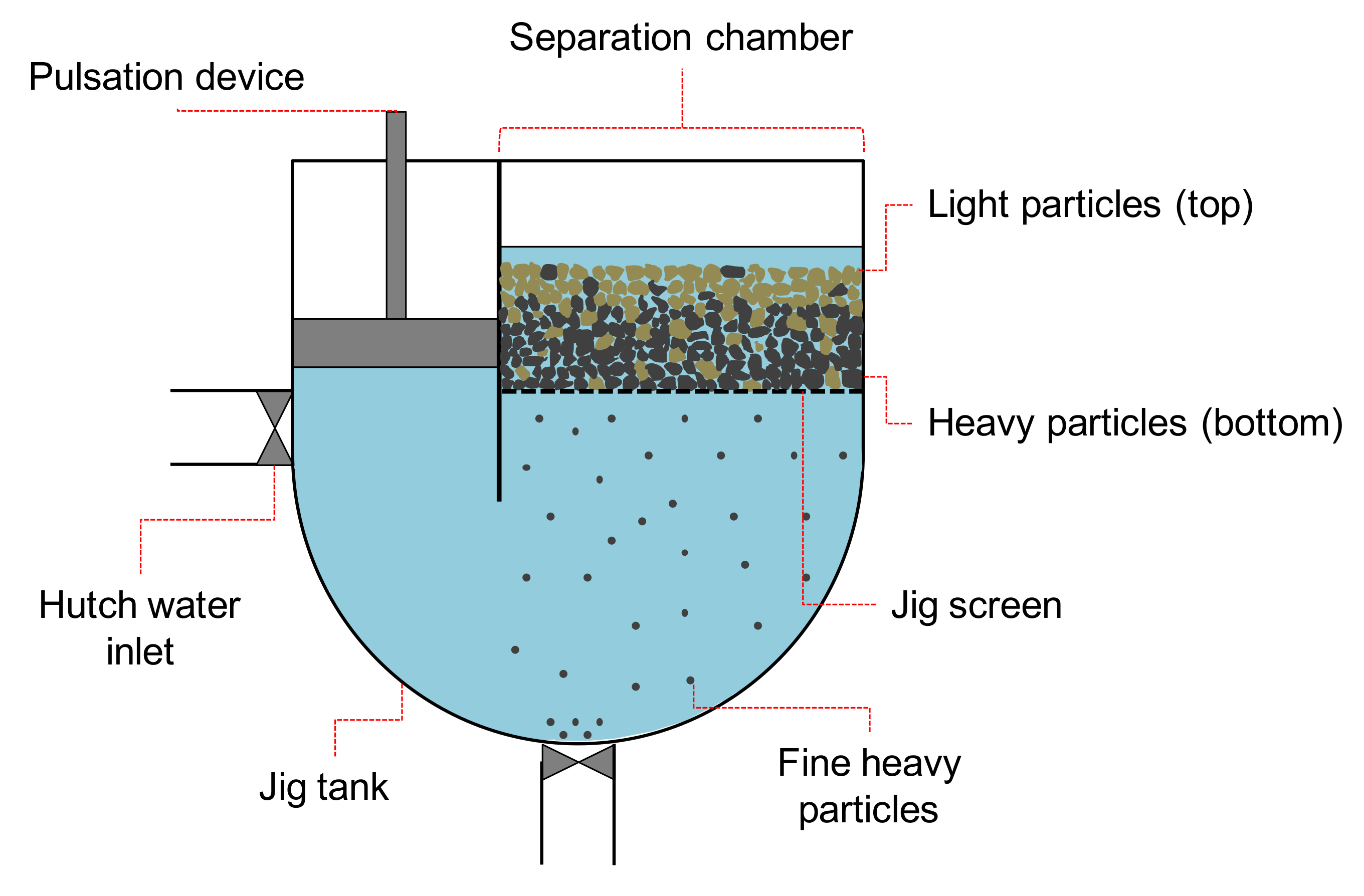
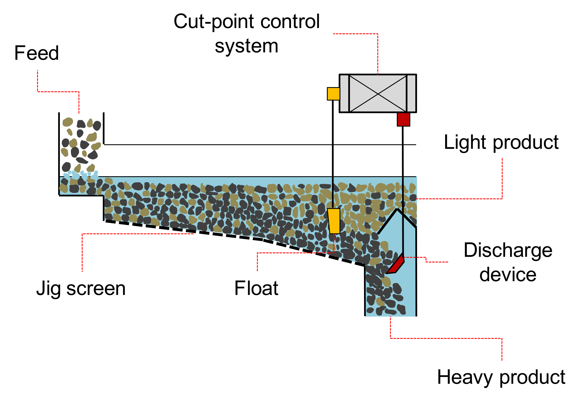
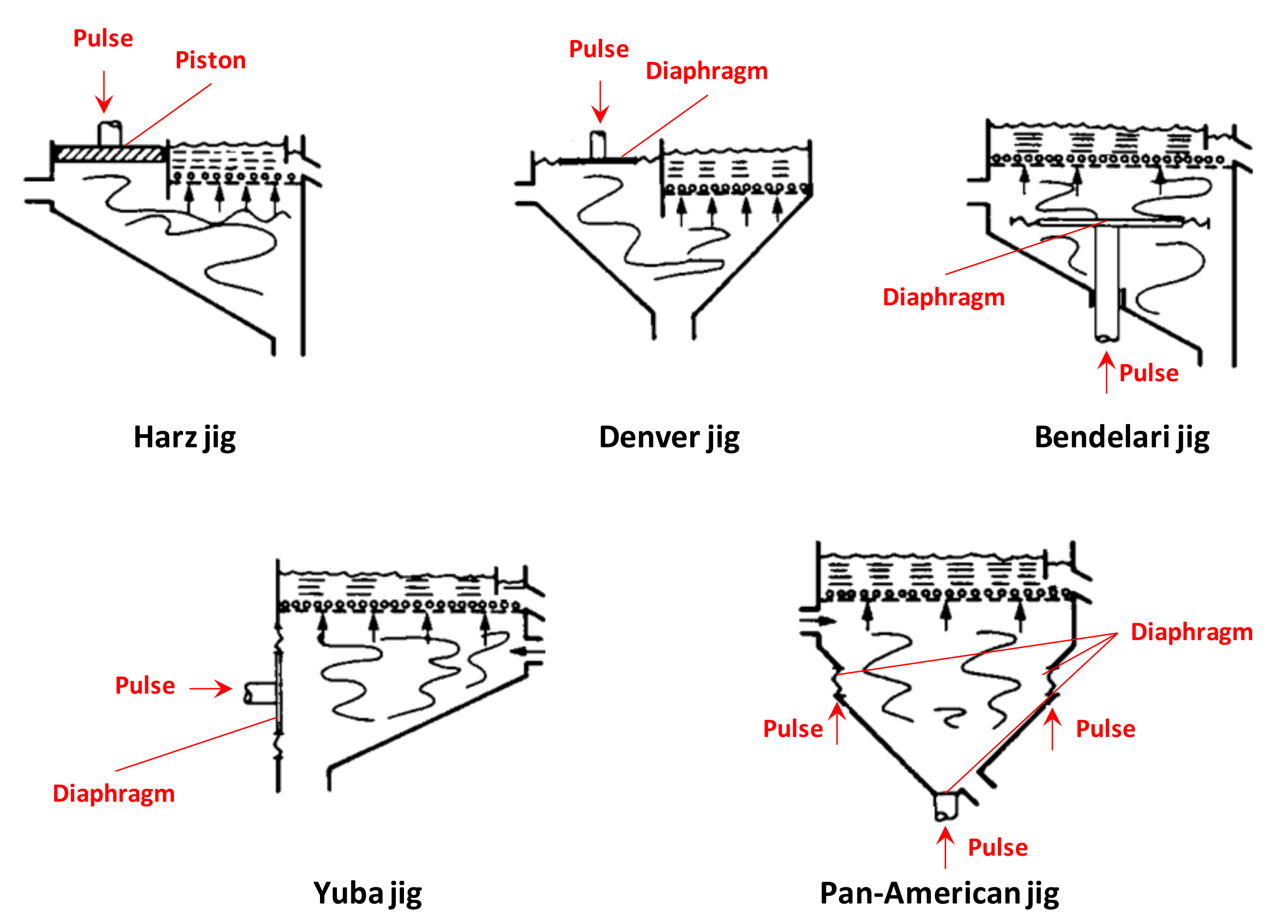
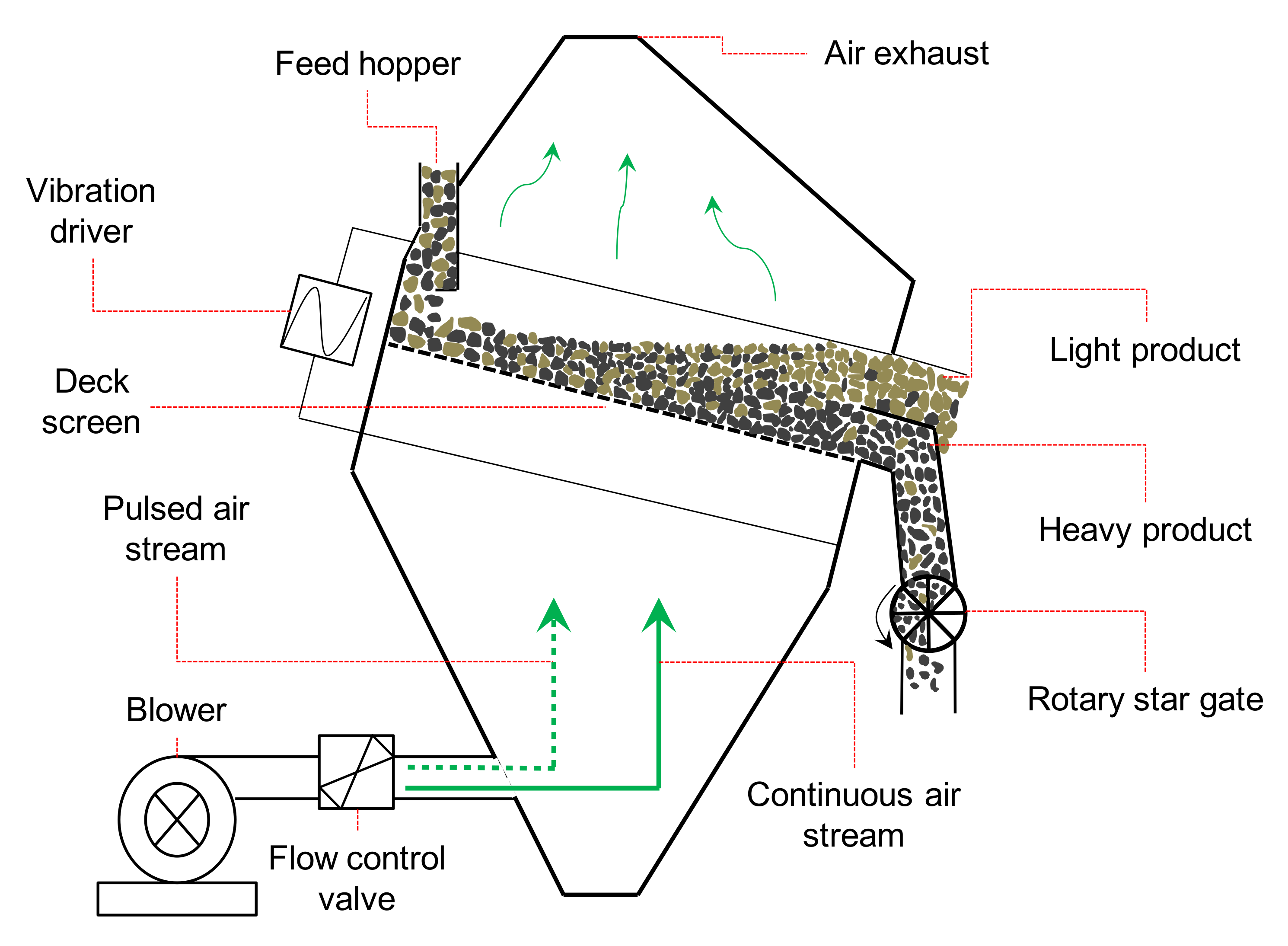
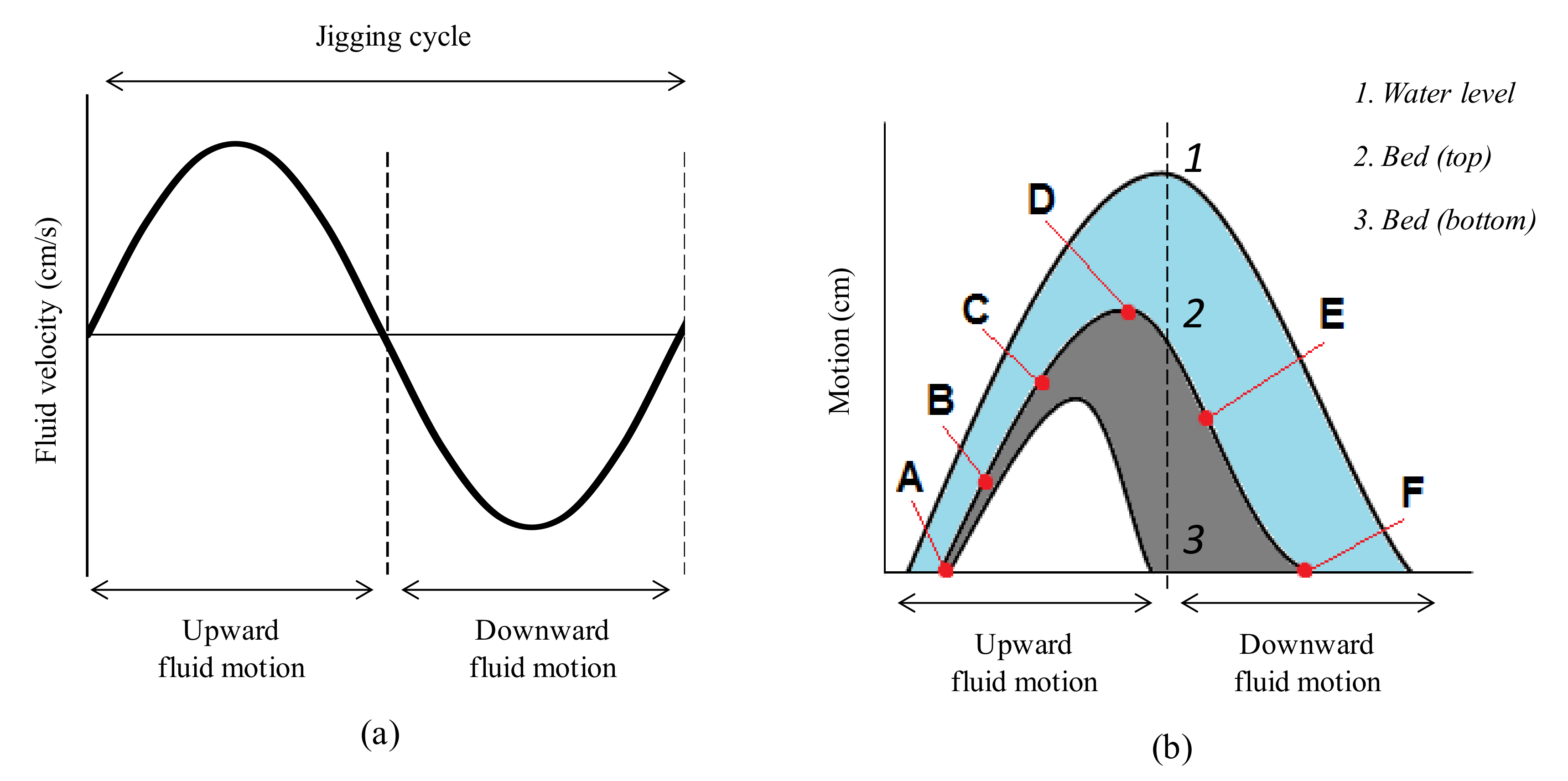
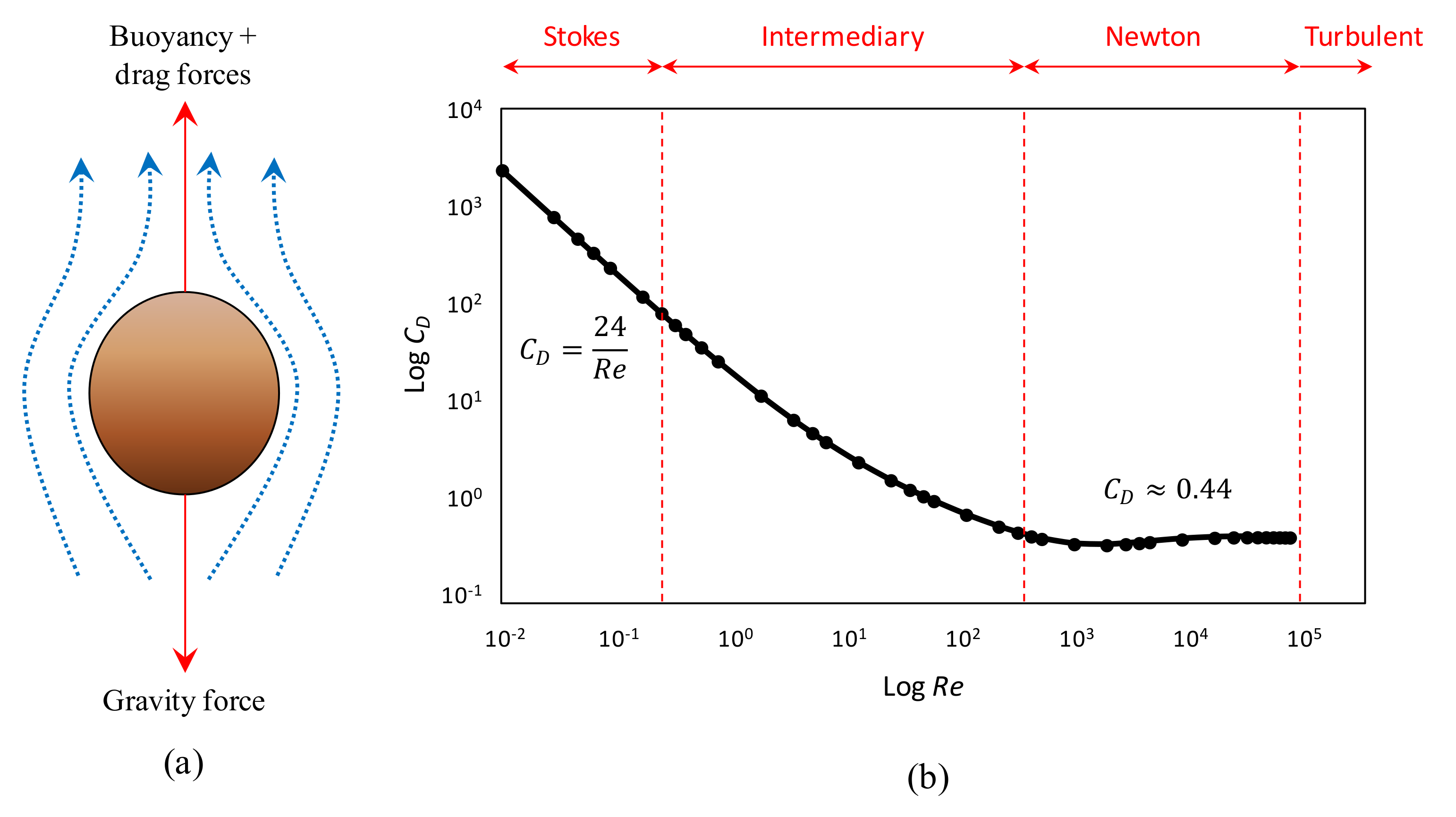
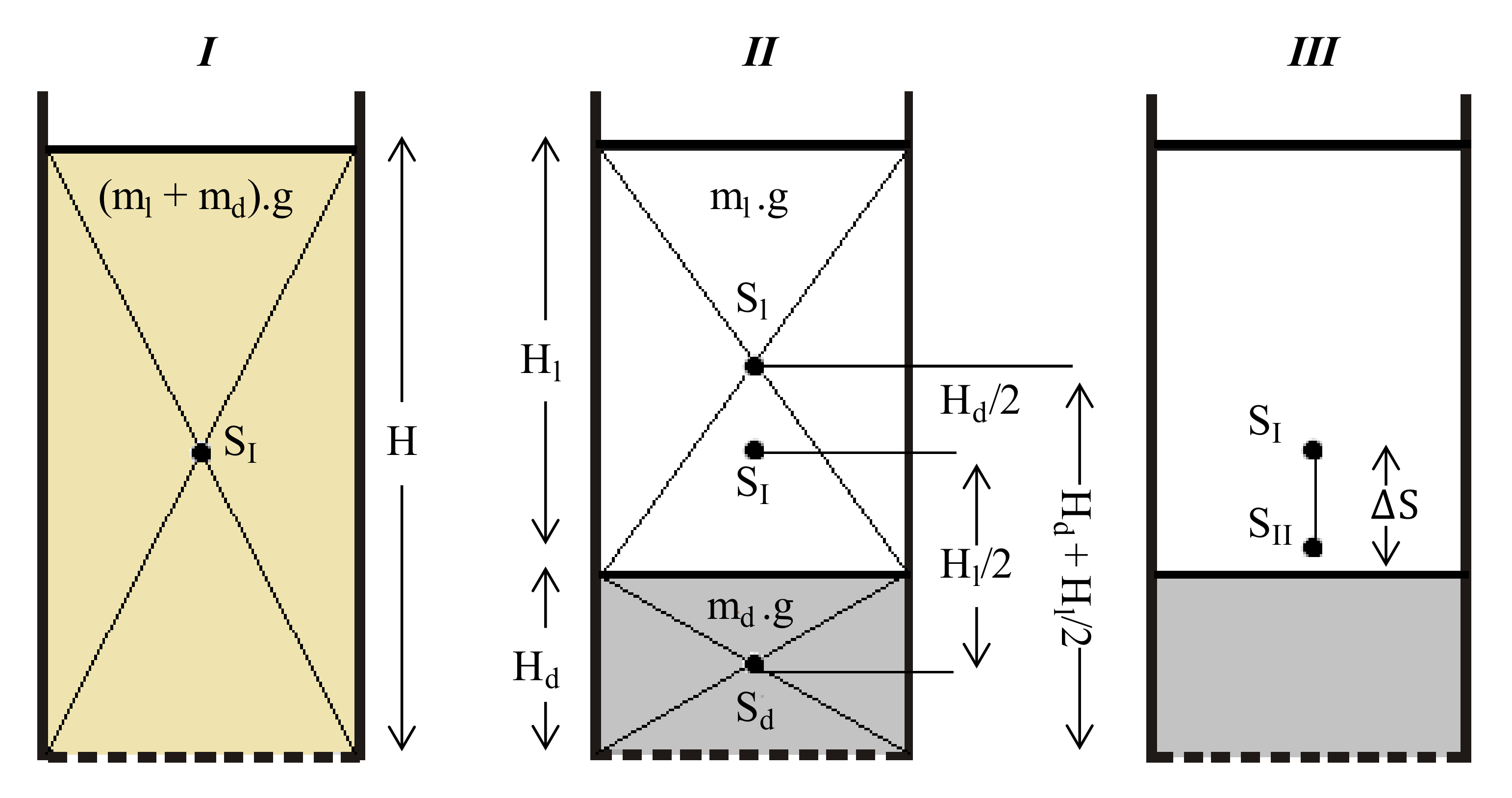
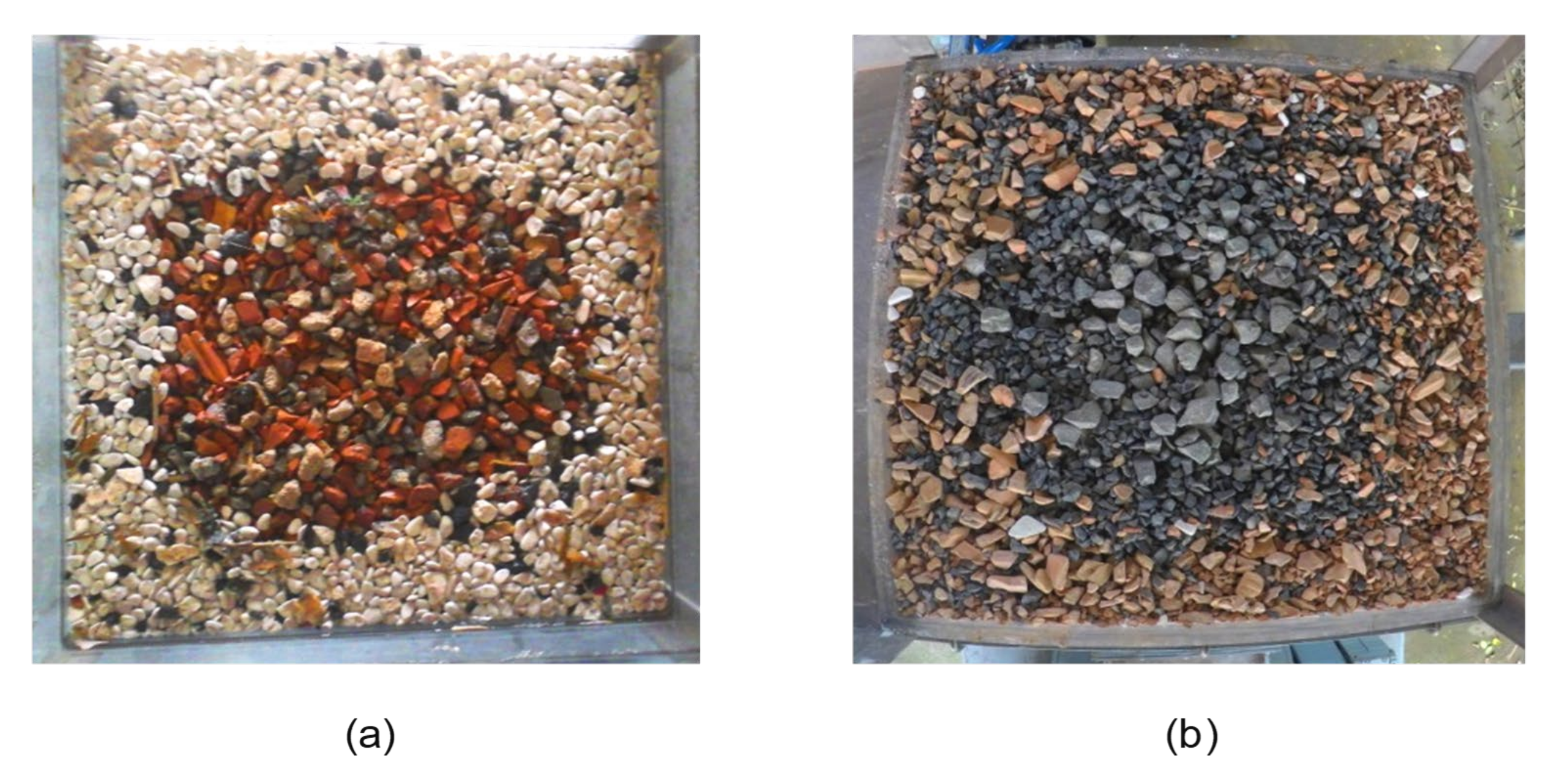
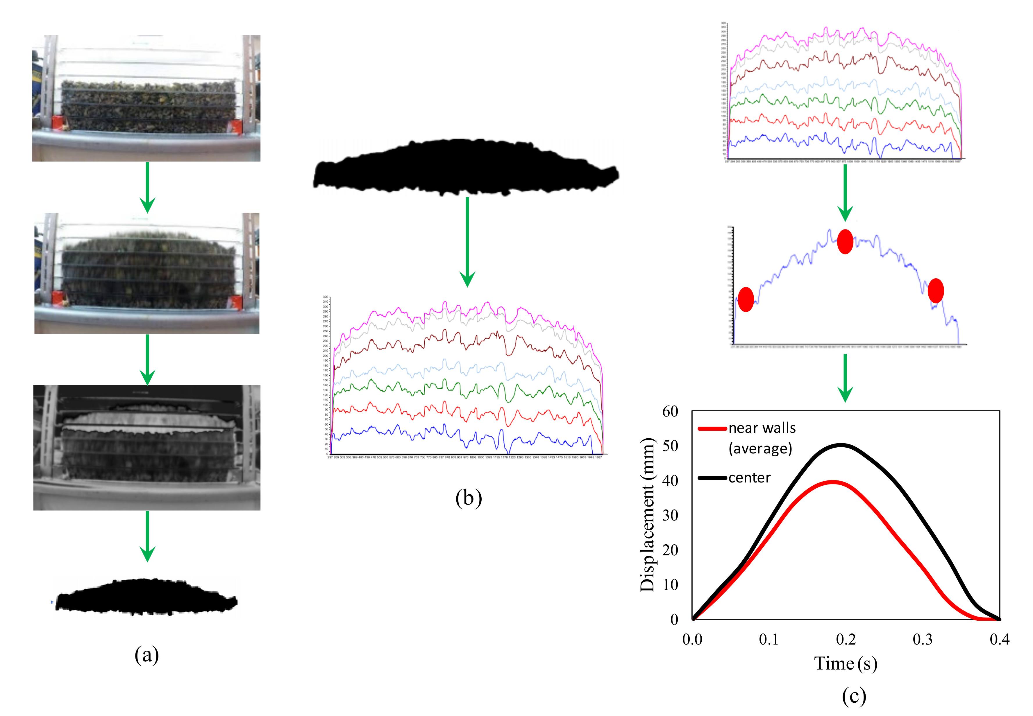
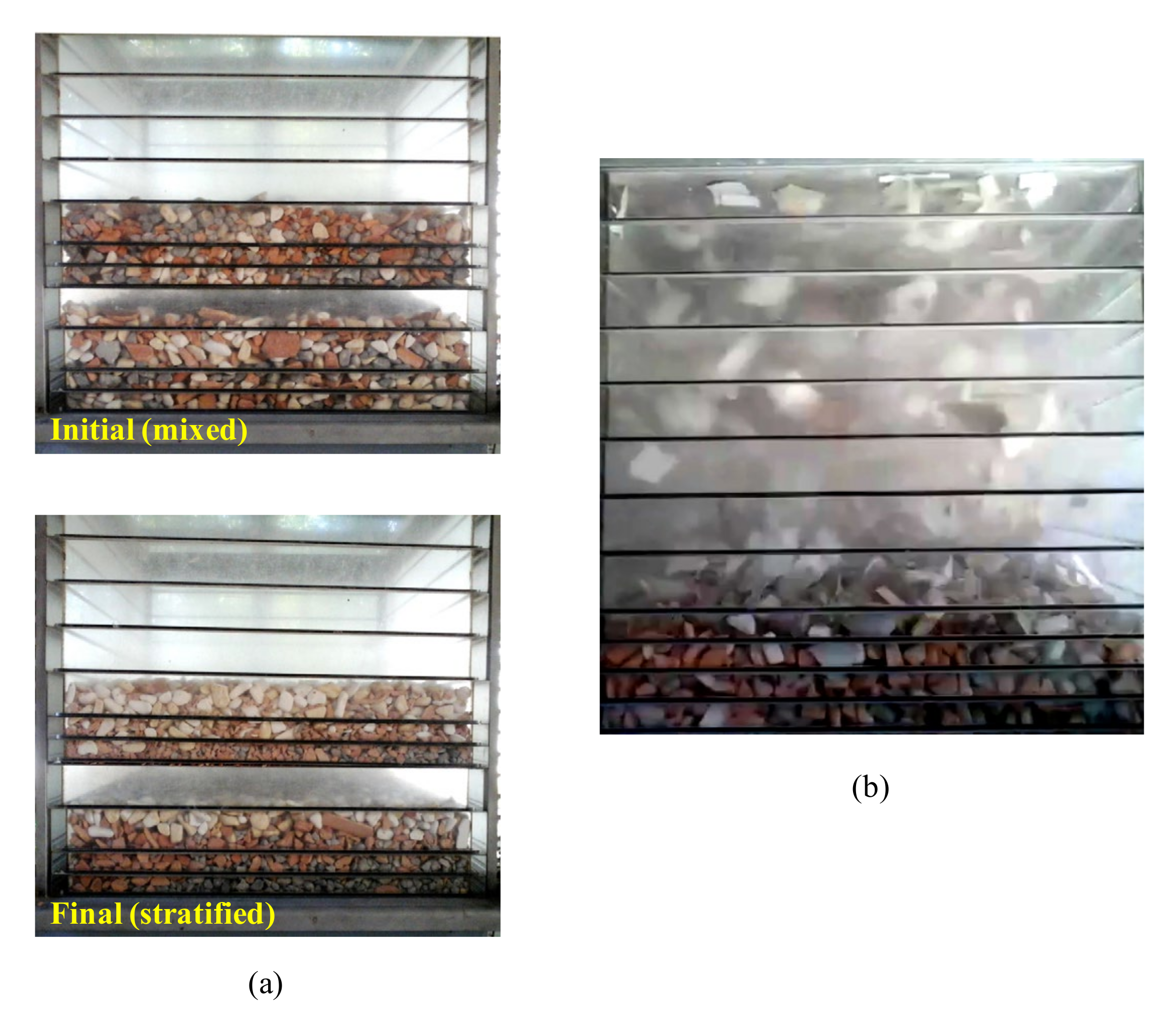
Table 1.
Types of jig according to the classification proposed by Sampaio and Tavares [8].
Table 1.
Types of jig according to the classification proposed by Sampaio and Tavares [8].
| Screen Type | Heavy Product Discharge | Pulsation Mechanism | Jig Equipment | Common Applications |
|---|---|---|---|---|
| Fixed screen | Over the screen | Piston | Harz | Coal |
| Diaphragm | Jeffrey | Coal | ||
| Bendelari | Ores | |||
| Air-pulsated | Baum | Coal and ores | ||
| Batac/Tacub | Coal and ores | |||
| Through the screen | Diaphragm | Denver | Ores | |
| Wemco/Remer | Ores | |||
| Yuba | Ores | |||
| Pan-American | Ores | |||
| IHC radial jig | Ores | |||
| Air-pulsated | Baum/Batac | Coal and ores | ||
| Mobile screen | Over the screen | Mechanic | ROMJIG | Coal |
| Through the screen | Mechanic | InLine Pressure Jig | Ores |
Publisher’s Note: MDPI stays neutral with regard to jurisdictional claims in published maps and institutional affiliations. |
© 2020 by the author. Licensee MDPI, Basel, Switzerland. This article is an open access article distributed under the terms and conditions of the Creative Commons Attribution (CC BY) license (http://creativecommons.org/licenses/by/4.0/).
Share and Cite
MDPI and ACS Style
Ambrós, W.M. Jigging: A Review of Fundamentals and Future Directions. Minerals 2020, 10, 998. https://0-doi-org.brum.beds.ac.uk/10.3390/min10110998
AMA Style
Ambrós WM. Jigging: A Review of Fundamentals and Future Directions. Minerals. 2020; 10(11):998. https://0-doi-org.brum.beds.ac.uk/10.3390/min10110998
Chicago/Turabian StyleAmbrós, Weslei M. 2020. "Jigging: A Review of Fundamentals and Future Directions" Minerals 10, no. 11: 998. https://0-doi-org.brum.beds.ac.uk/10.3390/min10110998
Note that from the first issue of 2016, this journal uses article numbers instead of page numbers. See further details here.