
A Novel Open-System Method for Synthesizing Muscovite from a Biotite-Rich Coal Tailing
by
 , and
, and
Hamid Khoshdast
1,*, 
Vahideh Shojaei
1,
Ahmad Hassanzadeh
2 ,
,
Tomasz Niedoba
3,* and
Agnieszka Surowiak
3 1
Department of Mining Engineering, Higher Education Complex of Zarand, 7761156391 Zarand, Iran
2
Independent Scholar, Am Apostelhof 7A, 50226 Frechen, Germany
3
Department of Environmental Engineering, Faculty of Mining and Geoengineering, AGH University of Science and Technology, al. Mickiewicza 30, 30-059 Krakow, Poland
*
Authors to whom correspondence should be addressed.
Minerals 2021, 11(3), 269; https://0-doi-org.brum.beds.ac.uk/10.3390/min11030269
Submission received: 28 December 2020
/
Revised: 28 February 2021
/
Accepted: 2 March 2021
/
Published: 6 March 2021
(This article belongs to the Section Mineral Processing and Extractive Metallurgy)
Abstract
:According to the wide application of muscovite in various industries, many studies have focused on its fabrication. However, the process of its synthesis faces long-standing challenges mainly related to the elevated temperature and pressure ambient, together with time and cost-consuming processes. This research work aims at synthesizing muscovite through a straightforward and direct wet thermal oxidation of an ash sample produced from biotite-rich coal tailings. For this purpose, the lab ash powder was mixed with 35% H2O2 at the room temperature of 25 °C while stirring at 480 rpm. Then, the temperature was gradually raised to 80 °C, and the process ran for 180 min. The dried product and the raw lab ash were characterized by the X-ray diffraction (XRD), scanning electron microscopy (SEM) and Fourier-transform infrared spectroscopy (FTIR) methods. The XRD results indicated that the biotite was efficiently converted to the muscovite as the number of relevant peaks was significantly increased in the synthesized product’s pattern. The SEM and FTIR results showed some structural changes, from pseudo-hexagonal in the starting material to amorphous pseudo-crystals in the synthetic product, as well as the growth of the product’s crystals. The crystallographic study and lattice parameter calculations revealed that the starting material and product peaks matched to International Center for Diffraction Data (ICDD reference patterns of 01-080-1110 and 01-082-2450 for the biotite and the muscovite, respectively. Moreover, the calculation of the mean crystallite size of the starting material and treated samples were obtained as 55 nm and 87 nm, respectively. Finally, according to the characterization properties of synthesized muscovite, the presented method was introduced as an effective technique. Therefore, we highly suggest it for further consideration and its development in future investigations.
1. Introduction
Biotite and muscovite are two phyllosilicate minerals within the mica family that are commonly found in igneous and metamorphic rocks. Biotite has a small number of commercial uses, while muscovite has the greatest commercial value due to its special properties. Muscovite mineral is chemically inert, dielectric, elastic, flexible, hydrophilic, lightweight, reflective and refractive [1]. In addition, it is stable when exposed to electricity, light, moisture and extreme temperatures. Muscovite, either in the form of sheet or ground, is used in joint compound, paint, drilling mud, plastics, rubber, asphalt proofing and electronic devices [2].
The generalized chemical compositions for biotite and muscovite as a potassium-rich mica are K(Mg,Fe)3(AlSi3O10)(OH,F)2 and KAl2(AlSi3O10)(OH)2, respectively [2]. Biotite is not very resistant to weathering and transforms into clay minerals. In contrast, muscovite is more resistant to weathering than biotite. In addition to weathering, the reduction/oxidation (redox) process is a pronounced mechanism resulting in mineral alterations. In the electrochemical series, Al3+ has a smaller redox potential (E° = −1.66 V) than Fe2+ (E° = −0.44 V) [3]. Therefore, Fe can be reduced and constituted by Al during the redox reaction. In the presence of a powerful oxidant such as hydrogen peroxide (H2O2), suitable conditions can be provided for 3Fe2+ ⇄ Al3+ substitution. This equilibrium can be postulated as the main substitution scheme during the synthesis process of muscovite from biotite. Other substitutions are Mg2+Si4+ ⇄ 2AI3+, K+A13+ ⇄ Si4+ and H3O+ ⇄ K+ [4].
In recent years, significant advances have been addressed in the field of clay material processing, which have mainly focused on the processing of clay materials from primary sources and the production of nano-clays and related compounds. Among them, the optimization of flotation [5,6,7] and leaching [8,9,10] methods have been considered more than other processing methods. Nano-clays have also been used mainly in combination with other organic and inorganic compounds in the form of composites to provide more beneficial physical and chemical properties [11,12,13,14,15,16,17]. In the case of muscovite, several synthesis procedures are described in the literature. These techniques can be categorized into four groups, including (I) reactions of phases of appropriate compositions, (II) recrystallization of decomposed natural mica, (III) alteration of natural minerals and (IV) structural modification. In the first method, a gel close to the requisite composition of muscovite is processed at 200–750 °C and 25–2000 atm for several days. The preparation methodology is mainly based on the work of Hamilton and Henderson [18]. The starting materials are a K salt, Al2O3 or Al(OH)3 and SiO2 in the proper ratios [19,20,21,22,23,24,25,26]. Applying this method highly requires the appropriate and precise proportions of the primary components and excessive energy, temperature and pressure values. In this context, Jungo and Schreyer [27] reported a detailed description regarding the pressure–temperature stability of synthesizing boromuscovite (KAl2BSi3O10(OH)2). In terms of method II, muscovite is resynthesized from its decomposition products. These materials are treated in a KOH solution at 400–650 °C and 100–700 atm for 12–100 h [28]. Synthesis through the third technique by the alteration of other minerals containing some of the necessary components has also been found to be fruitful by several investigators [29,30,31,32]. This method includes heating a mica mineral with H2O at 200–600 °C and 250–350 atm for tens of days. H2O may be enriched by K2O to promote the synthesis procedure [33]. Although this is an effective approach and commonly used in the literature, its time-consuming process might be taken as one of its drawbacks. In structural modification method (IV), the composition of muscovite, is modified by an elemental substitution, e.g., fluorine–hydroxyl exchange in synthetic muscovite [34,35]. In addition to these techniques, Yuan and coauthors recently developed a sustainable and energy-saving approach for synthesizing nano-muscovite through a green chemical process by imitating the geochemical weathering process of k-feldspar [1]. This technique led to the production of muscovite with 20–45-nm thickness under hydrothermal conditions of 250 °C for 18–72 h by adjusting the ratio of n(H+)/n(k+) in the presence of acetic acid (CH3COOH > 99.5%). By developing modern technologies, the demands for muscovite with specific sizes and qualities increase. Therefore, several studies have been conducted on its characterizations and applications. However, in recent years, the access to rich primary mineral resources and advances in the processing methods of these materials, especially the froth flotation process, have reduced the tendency to develop muscovite synthesis methods from other sources (i.e., secondary sources or individual starting materials). Moreover, although the discussed methods have given acceptable synthesis efficiency, the requirements of an extremely high temperature, pressure and process duration made them cost-intensive.
Given the significant reduction in high-quality mineral reserves, the search for efficient methods to extract, synthesize or recycle materials needed by industries from secondary sources is the simplest way to respect the rights of future generations and maintain their share of the existing primary reserves. For example, annually, millions of tons of coal tailings are produced by coal beneficiation plants around the world and disposed in dumping sites. These coal residues can cause serious ecological and environmental problems due to potential contaminant transport issues. These problems can include the transportation of contaminants like heavy metals [36] and nano-minerals [37] from dumping sites, which leads to the contamination of groundwater and surface water sources. Additionally, other issues can be caused through the self-ignition of dry dumping sites and the pollution of surrounding environments with respect to the dispersion and emission of coal dust by wind. Regardless of their environmental impacts, these materials can be thought of as potential secondary resources, provided appropriate recycling methods are developed [38,39]. During the last decades, many attempts were made for the recycling and reusing of these materials. For example, the recovery of coal from coal waste and tailings has been considered by some small companies to produce low-energy briquette for domestic consumption, due to the high ash content [40]. The reuse of coal wastes in other fuel forms has also been considered by some researchers. For example, Opara et al. [41] investigated the production of biomethane from coal wastes and suggested that these materials can be used as a commercially viable source for the production of methane fuel. Zheng et al. [42] used a microbial consortium derived from sewage sludge for the production of methane from a coal waste sample and showed that coal waste can be partially digested into biomethane. Recently, Dmitrienko and Strizhak [43] showed that fine coal wastes in the form of coal–water slurry can yield better combustion properties. Vershinina and coworkers [44] evaluated the combustion characteristics of organic coal–water fuels produced by different oils and coal-processing wastes of different grades and reported that the development of coal–water fuel technology can be used as an efficient solution for coal waste recycling. Some researchers have investigated the potential applications of coal wastes in the manufacturing of construction products, such as cement [45], asphalt [46,47,48], brick [49,50] and concrete [51]. Despite the remarkable results of the above studies, their applicability has been limited due to large mineral–petrographic variations, fragmentations and low-energy characteristics. The noncombustible part of coal tailings, called ash, usually contains significant amounts of oxides of aluminum, iron and silicon and rare earth elements that can be used as raw materials in the synthesis of clay-type compounds. Referring to the literature indicates that the studies to date have mainly focused on the synthesis of zeolitic compounds from these materials [52,53,54,55,56,57,58,59], and to the authors’ best knowledge, no study has been yet reported on the synthesis of muscovite from these materials. Therefore, in this paper, a simple open system method is introduced to synthesize muscovite from a lab ash produced from biotite-rich coal tailings. The crystalline properties of the synthesized samples were investigated through the common characterization techniques.
2. Materials and Methods
2.1. Material and Its Preparation
A representative sample of coal tailings from Zarand Coal Washing Plant, Iran was used as the starting material for the synthesis process. Previous investigations showed that the noncombustible contents of these materials are rich in biotite [60]. Therefore, they can be considered as an abundant source for muscovite synthesis. Sampling was performed using a standard sampling scoop to prepare the representative sample for chemical analysis and synthesis experiments. The sampling program from the underflow stream of tailings thickener was scheduled for three days, with 2-h time steps at every work shift. Afterward, the samples were filtered, dried in an oven at 60 °C and mixed to obtain a 10-kg bulk sample.
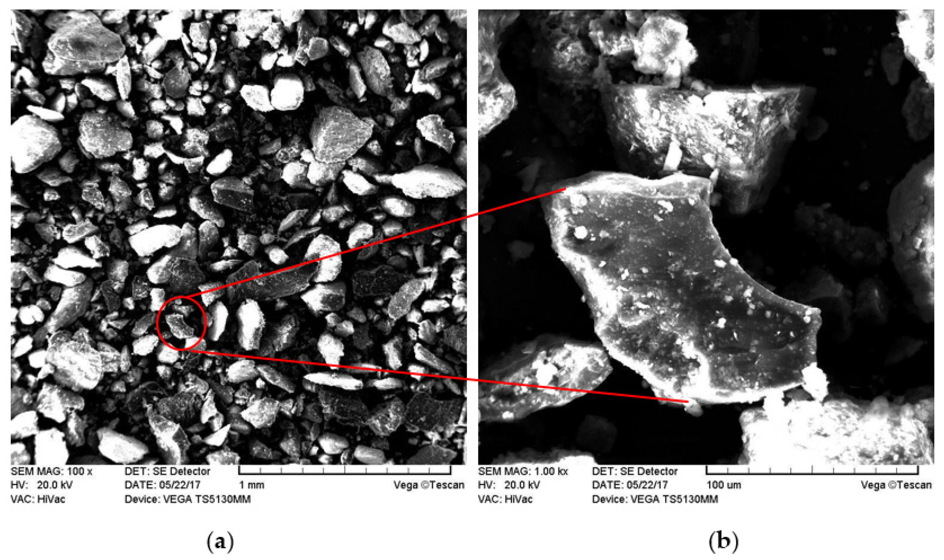
The SEM image of the coal tailings is shown in Figure 1. As seen, the sample includes angular particles with no unusual surface patterns and excessive void spaces. In addition, as shown in Figure 1a, the samples are expected to have a fairly limited particle size distribution. Figure 1a demonstrates a large scale of the starting sample, while Figure 1b exhibits the surface microstructures with a reasonable contrast and resolution. The noncombustible contents of each sample were measured using a typical ash analysis procedure according to the American standard test sieve (ASTM D 3174-73), showing that the sample had 68.12% ash content. To produce the ash sample from the tailings, 60 samples of 1 g of coal tailings were milled and then heated up in a porcelain crucible at 850 °C for 8 h. These ash residues were used as the starting materials for synthesis studies. The chemical composition of the ash material was characterized using X-ray fluorescence (XRF, PW1480, Philips) and given in Table 1. As seen, SiO2 and Al2O3 with respective magnitudes of 49.1% and 25.8% are the dominate components of the ash sample. In other words, alumina and silica oxide are present in major quantities; however, other minerals exist in trace amounts. This confirms the chemical analysis of the clay. It is worth mentioning that LOI is the loss on ignition in the head sample. Since the material studied here is taken from a coal tailing, it contains hydroxy compounds, which includes a high level of combined water as adsorbed and/or intracrystalline water. These components are shown later in the FTIR analysis.
2.2. Synthesizing Approach
Referring to the chemical composition of biotite and muscovite, it is possible to transform biotite to muscovite by harsh oxidation. This can be achieved by a strong oxidant like hydrogen peroxide at the appropriate heating level. The procedure presented in this paper is based on a feasibility study in which a set of preliminary experiments were conducted to obtain the optimum conditions for the synthesis process as follows [60]. Initially, 20 g of the prepared lab ash was placed in a 500-mL glass beaker, and 250 mL volume of 35% H2O2 (Sadrashimi Chemical Co., Isfahan, Iran) was added at room temperature (25 ± 1 °C) with continuous stirring at 480 rpm. Then, the temperature was gradually raised to 80 °C. The synthesis was performed in an open system using a stirrer–heater equipped with a thermostat to adjust the temperature to 80 ± 2 °C, with continuous stirring for 180 min. Finally, the slurry mixture was centrifuged at 10,000× g for 20 min (Sigma 1-14, Osterode am Harz, Germany), and the precipitate was placed into a porcelain-evaporating basin and aged in an oven for 20 h at 95 °C.
2.3. Characterization
The phase determination and phase analysis were carried out by the X-ray diffraction (XRD, PHILIPS, X’pert-MPD system, Amsterdam, The Netherlands). In order to prepare the sample for XRD analysis, the ash product of the coal tailing was first ground into a fine powder (<75 μm) and then mixed with a suitable binding aid (a cellulose wax mixture combined with the sample in a proportion of 20% binder-to-sample). Afterwards, the mixture was pressed in a dye at 20 T to produce a homogeneous sample pellet. IR spectra were recorded on a Fourier-transform infrared spectrometer (FTIR, Bruker tensor 27, Berlin, Germany) with a RT-DLATGS detector. The morphology of the samples was determined by scanning electron microscopy (SEM) (Tescan Vega-II, Brno, Czech Republic). Seven-point analyses were performed on both the starting material and product.
The crystallite sizes of the samples were calculated using the Scherrer equation [61,62,63]. The crystallization system of the starting material and product was determined based on the X-ray method. Then, the lattice parameters were calculated in terms of the strongest high-angle reflections, so that the peaks were divided into Kα1 and Kα2 components at each reflection. The lattice parameters of the samples were calculated from the interception of the ordinate in the Nelson–Riley plot, i.e., a plot of the lattice parameter determined from individual reflections vs. cos2θ/sinθ [63].
3. Results and Discussion
3.1. XRD and SEM Analyzes
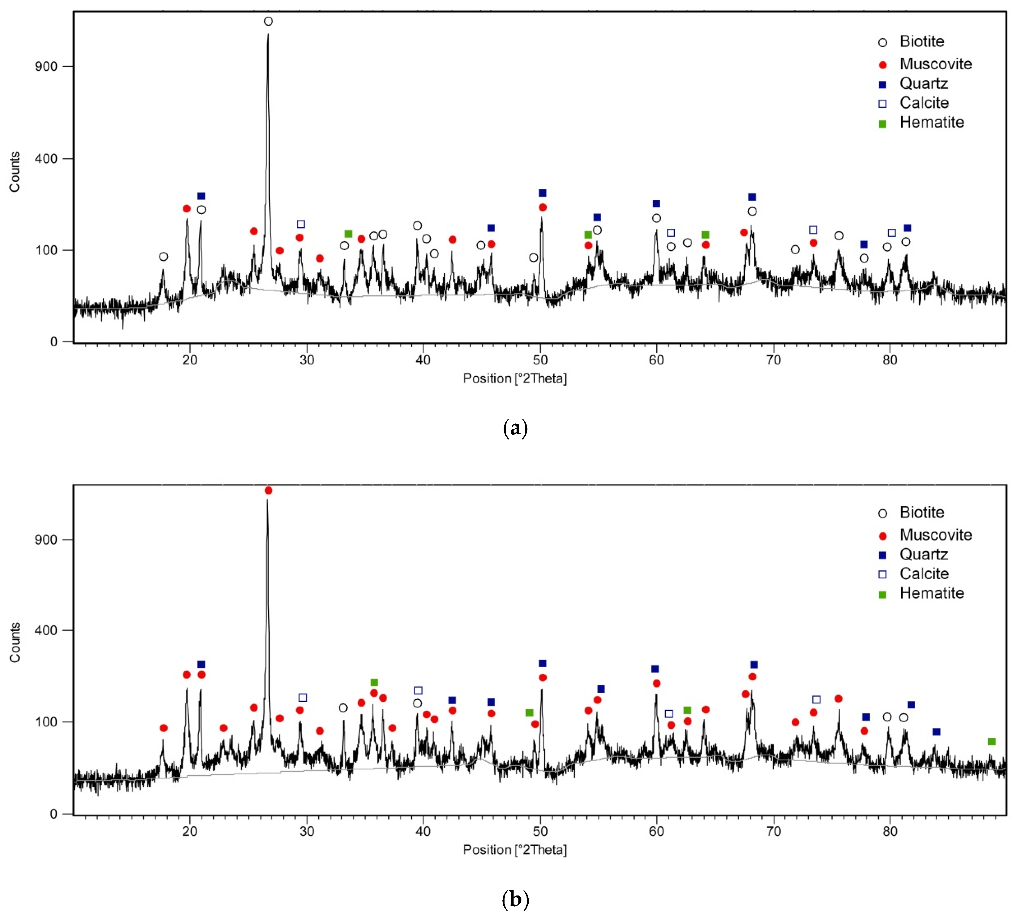
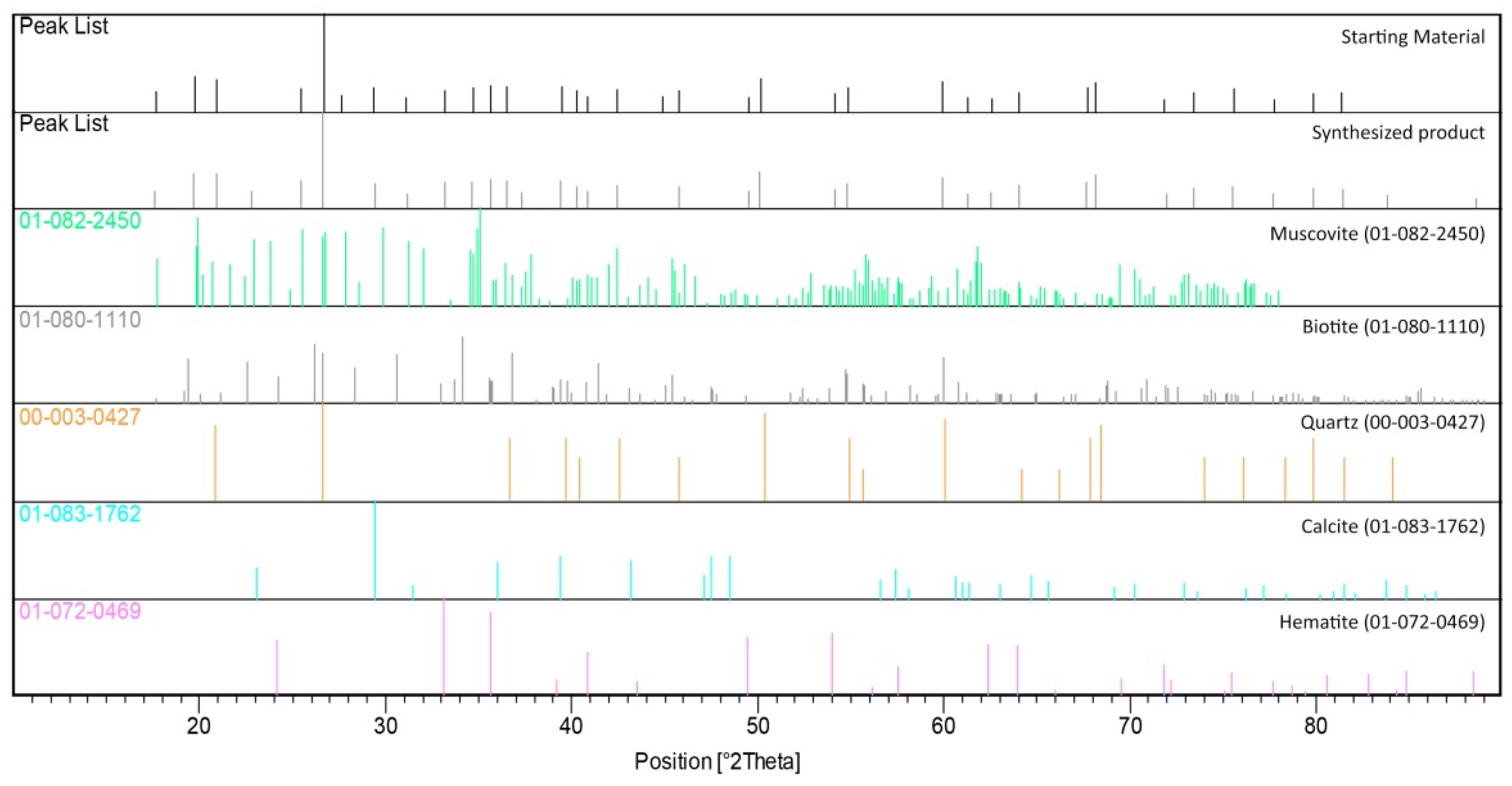
Figure 2a,b shows the XRD patterns of the starting material and synthesized product, respectively. The reference patterns are also shown in Figure A1 (Appendix A). By qualitatively comparing the results of both Figure 2 and Figure A1, it was clear that the ash sample was a mixture of biotite and muscovite. Figure 2b illustrated that most of the diffraction peaks related to the biotite were converted into muscovite. These transformed phases obviously confirmed that the suggested process for the synthesis of muscovite from the biotite-rich lab ash was successful. To evaluate the conversion efficiency, the XRD patterns were quantitatively analyzed, and the muscovite content of the starting material and synthesized product were found to be 28.7% and 67.7%, respectively.
It should be noted that, since the main purpose of this study was to investigate the conditions of the conversion of biotite to muscovite, the presence of other minerals was not studied. Additionally, XRD patterns were analyzed only for the dominant and target phases—namely, biotite and muscovite. However, for the sake of clarity, the XRD results were also quantitatively analyzed and are presented in Table A1.
Table 2 shows a comparison between the calculated and standard lattice and crystallographic parameters for biotite and muscovite. Cell axes in the monoclinic unit cell were of unequal lengths. Cell dimensions were a = 5.34, b =,9.24 and c = 10.21 Å for biotite and a = 5.19, b = 9.01 and c = 20.06 Å for muscovite. This manifested, because muscovite crystals faced in the direction of the c-axis larger than biotite. Therefore, it was expected that the synthesized product had larger crystals compared to the ash material.
Comparing the X-ray patterns of the starting material and treated product with the standard patterns showed that the starting material’s peaks matched the ICDD reference pattern 01-080-1110 for biotite, and the product peaks matched the ICDD reference pattern 01-082-2450 for muscovite (Appendix A, Table A2).
In addition to high-angle reflections, the low-angle reflections were used to determine the lattice parameters of the samples. The Ka1 and Ka2 peaks for biotite and muscovite are given in the Appendix A (Table A2 and Table A3). Then, for each reflection angle, parameter d was determined using the Bragg equation below (Appendix A, Table A4 and Table A5) [63]. These results were used for calculating the lattice parameters. After solving the equations, the lattice parameters were determined for the high reflections. Then, based on the Nelson–Riley equation and regression, the final lattice parameters were defined as shown in Table 3.
Referring to the standard amounts of the lattice parameters (Table 3), it revealed that the calculated lattice parameters for the starting material and product were significantly closed to the standard parameters. These results confirmed that the starting material was biotite, and the synthesized product was muscovite, with high crystallographic compliance. Table 3 also shows that the difference between the muscovite beta angle of the standard and product is one degree. In general, the process of analyzing and identifying the results of the XRD analysis is based on comparing the XRD pattern of the sample with the patterns that are available in the analysis software database. The result of this study is the selection of reference codes that are the most consistent with the sample pattern, and therefore, it is obvious that differences are observed in some crystallographic parameters.
The selected reference pattern may belong to a natural muscovite, whereas the muscovite sample in this study is a synthetic product with some defects in the crystallographic structure caused during the synthesis process. Therefore, the apparently significant difference in the beta angle of the reference and product muscovite can be attributed to the aforementioned reasons. The crystallographic information of some standard muscovite minerals available in the XRD Pattern Library is presented in Table 3. As can be seen, the beta angle difference in the standard samples can vary up to more than two units.
The mean crystallite sizes of the starting and treated samples were calculated to be 55 ± 0.09 nm and 87 ± 0.23 nm, respectively. These values verified the growth of the product’s crystals, as observed in the SEM images. Both the crystallite size and morphology shown in Figure 2b verify a potential application of the product as an additive material in different industries, such as the coating paint of automobile industries, mica-paper fabrication and mica-glass ceramic [1].
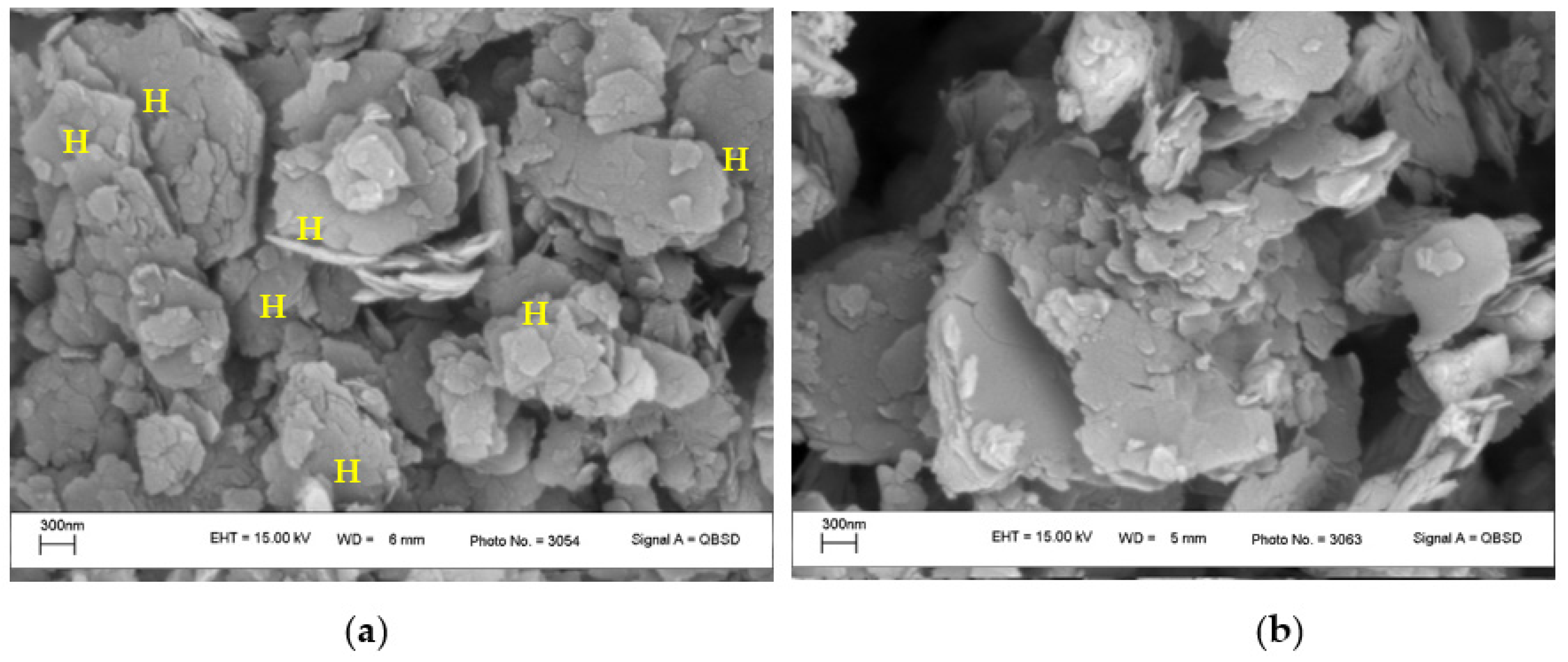
Figure 3a,b represents the SEM images of the starting material and synthesized product, respectively. The SEM photographs revealed the differences among the biotite and muscovite structures. Biotite was crystallized in a monoclinic system with tabular-to-prismatic crystals with an obvious pinacoid termination. It has four prism faces and two pinacoid faces to form a pseudo-hexagonal crystal (designated by “H”), which can be observed in Figure 3a. In contrast, muscovite was crystallized in a monoclinic system with amorphous pseudo-crystals. This conclusion is found to be in line with the results addressed in the literature [2,64]. A comparison between Figure 3a,b clearly shows that the pseudo-hexagonal crystals were disappeared after the synthesis to amorphous pseudo-crystals. This crystalline conversion can be considered as evidence of biotite-to-muscovite conversion.
3.2. Infrared Spectroscopy Results
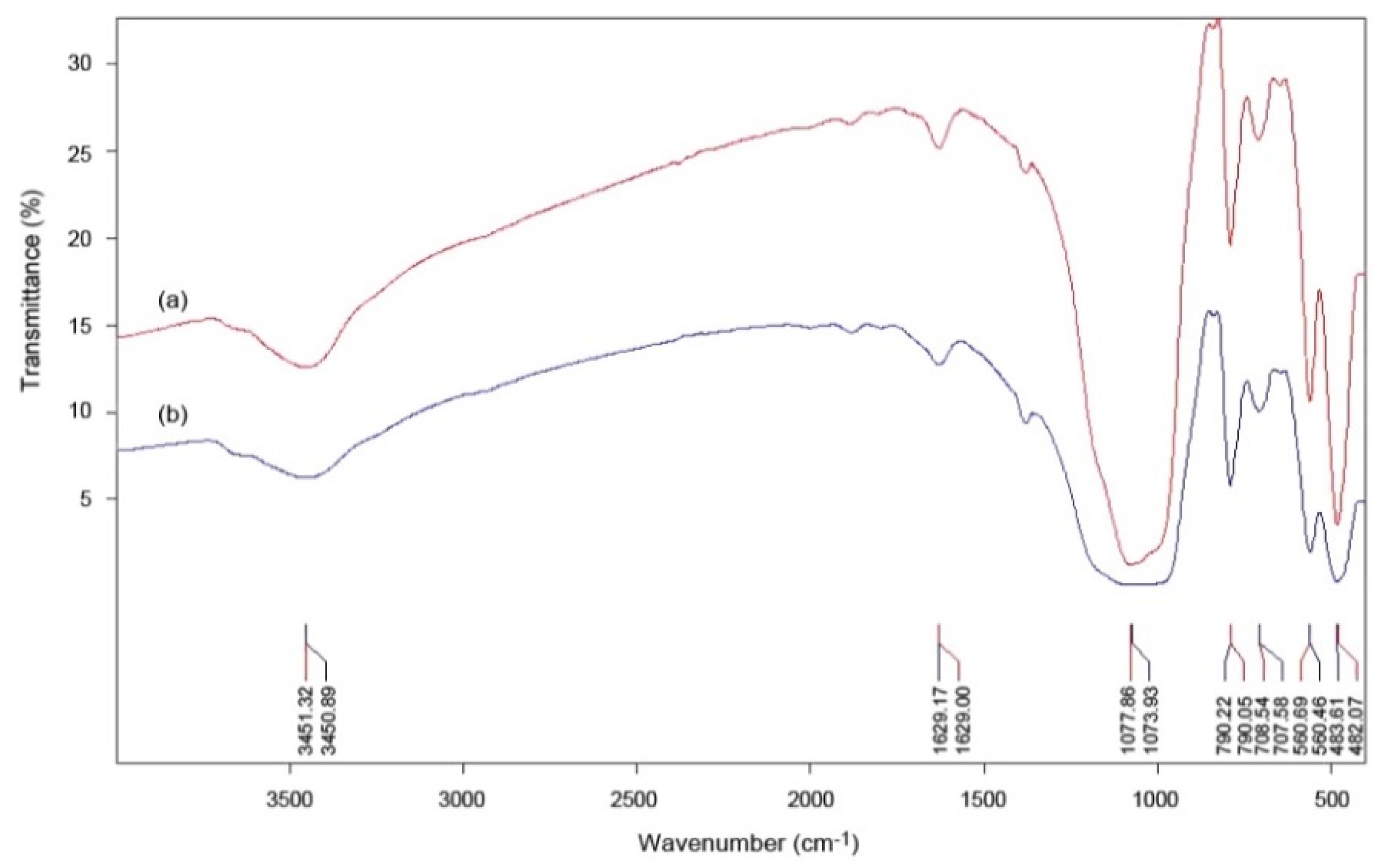
Figure 4a,b exhibits the FTIR spectrum of the starting material and treated product, respectively. Since both samples were mixtures of biotite and muscovite, it was difficult to distinguish the peaks corresponding to each mineral. However, these spectra were similar to those reported in the literature [26,65,66,67,68,69]. The band positions for the starting material and synthesized product are given in Table 4. The hydrous nature was confirmed by the FTIR analysis showing the presence of –O–H bonds at 3451.32 and 3450.89 cm−1 for the starting material and synthesis product, respectively. Further, the Si–O stretching vibrations were observed at 1073.93, 560.46 and 483.61 cm−1 for the product representing the presence of quartz, as can be confirmed by Table A1 and addressed by Marel and Bentelspacher [70] in the literature. Si‒O‒Al stretching vibrations at 707.58 and 560.46 cm−1 correspond to the possibility of the presence of calcite, as given in Table A1. In this context, Gadsen [71] identified a band at 693⋅4 cm−1 for calcite, which is in the range of our findings. At the wavelengths of 1077.86 and 1073.93 cm−1, the peak of the starting material was relatively sharper than that of the synthesized one, most likely due to its higher content of biotite and/or quartz [72]. As can be seen in Table 4, this peak is dedicated to the Si–O stretching vibrations that identify quartz and include 3.9 wt% and 2.7% of the starting and produced materials. In addition, the higher sharpness of the peaks in Figure 4 indicated that the crystals contained in the starting material were more regular than the crystals of the treated sample [73,74]. In this regard, the SEM photographs also showed a clear growth in the dimensions of the muscovite crystals.
4. Conclusions
The present study proposes a potential method for synthesizing muscovite from an ash sample produced from biotite-rich coal tailings using an easy and open system process. In contrary with the other techniques, this approach is a safer and, more importantly, shorter process. The synthesized muscovite properties and efficiency of the conversion process were evaluated by the XRD, SEM and FTIR analyses. The XRD pattern of the synthetic product proved that the conversion was successfully achieved. The conversion also appeared in the FTIR and SEM results through crystalline growth and change from biotite’s pseudo-hexagonal crystals to muscovite’s amorphous pseudo-crystals. Additionally, the crystallography study and lattice parameter calculations confirmed the analytical results. It was found that the mean crystallite size of the starting material grew from 55 ± 0.09 nm to 87 ± 0.23 nm in the case of the synthesized product. These results are in agreement with those observed in the SEM images. From the findings in this study, the proposed method seems to be a promising and potential bedrock process. For future investigations, we believe this process may need further optimization and detailed characterizations. Moreover, the descriptions of the reactions involved in the phase changes from the thermodynamic and kinetic point of views can be considered as future studies.
Author Contributions
Conceptualization: H.K. and V.S.; methodology: H.K. and V.S.; original draft preparation: H.K. and V.S.; writing—reviewing and editing: H.K., V.S., A.H., T.N. and A.S.; investigation: H.K. and V.S. and visualization and supervision: H.K. and V.S. All authors have read and agreed to the published version of the manuscript.
Funding
This research received no external funding.
Institutional Review Board Statement
Not applicable.
Informed Consent Statement
Not applicable.
Data Availability Statement
Not applicable.
Acknowledgments
The authors would like to acknowledge FOCUS® Minerals Engineering Research Center (Zarand, Iran) for its technical supports. Additionally, we thank the anonymous reviewers for their insightful remarks, constructive comments and fruitful criticisms.
Conflicts of Interest
The authors declare no conflict of interest.
Appendix A
Experimental and reference XRD patterns.
Figure A1.
Experimental XRD patterns vs. reference patterns of the starting material and synthesized product.
Figure A1.
Experimental XRD patterns vs. reference patterns of the starting material and synthesized product.


Table A1.
Major and minor phases in the starting material and synthesized product.
| Phase | Major Phases (wt%) | Minor Phases (wt%) | |||
|---|---|---|---|---|---|
| Sample | Biotite | Muscovite | Quartz | Calcite | Hematite |
| Starting material | 64.4 | 28.7 | 3.9 | 2.0 | 1.0 |
| Product | 27.6 | 67.7 | 2.7 | 1.0 | 1.0 |
Table A2.
Ka1 and Ka2 peaks for the reflections of the starting material.
| 2θ (Degree) | d (Å) | hkl | Kα1 (Degree) | Kα2 (Degree) |
|---|---|---|---|---|
| 39.4824 | 2.282 | 220 | 39.448 | 39.55 |
| 44.8831 | 2.01953 | 005 | 44.844 | 44.961 |
| 71.8665 | 1.31372 | 064 | 71.797 | 72.003 |
| 75.5809 | 1.25811 | 262 | 75.507 | 75.728 |
| 77.7888 | 1.22783 | 172 | 77.712 | 77.942 |
| 79.8642 | 1.20106 | −405 | 79.785 | 80.023 |
| 81.4022 | 1.18124 | −228 | 81.402 | 81.647 |
Table A3.
Ka1 and Ka2 peaks for the reflections of the product.
| 2θ (Degree) | d (Å) | hkl | Kα1 (Degree) | Kα2 (Degree) |
|---|---|---|---|---|
| 34.6530 | 2.58863 | 200 | 34.623 | 34.712 |
| 40.2683 | 2.23967 | 220 | 40.233 | 40.338 |
| 50.1131 | 1.82034 | 0210 | 50.069 | 50.202 |
| 63.9994 | 1.45483 | 0213 | 63.940 | 64.118 |
| 68.1187 | 1.37655 | −337 | 68.054 | 68.247 |
| 71.9970 | 1.31164 | −1115 | 71.928 | 72.135 |
| 73.4356 | 1.28946 | 068 | 73.365 | 73.577 |
Table A4.
Calculations of the d-spacing based on the Braggs equation for the starting material.
| 2θ | θ (Radian) | Λ | Sinθ | Sin2θ | λ α12/λ α22 | Sin2θ | h | k | l | 4(Sin2θ)/λ2 |
|---|---|---|---|---|---|---|---|---|---|---|
| 39.448 | 0.344249 | kα1 | 0.33749 | 0.1138992 | 0.995048962 | 0.1138992 | 2 | 2 | 0 | 0.191965649 |
| 39.55 | 0.345139 | kα2 | 0.338327 | 0.1144654 | 0.995048962 | 0.1138987 | 2 | 2 | 0 | 0.191964722 |
| 44.844 | 0.391338 | kα1 | 0.381425 | 0.1454853 | 0.995048962 | 0.1454853 | 0 | 0 | 5 | 0.245200787 |
| 44.961 | 0.392359 | kα2 | 0.382369 | 0.146206 | 0.995048962 | 0.1454822 | 0 | 0 | 5 | 0.245195507 |
| 71.797 | 0.626547 | kα1 | 0.586351 | 0.3438077 | 0.995048962 | 0.3438077 | 0 | 6 | 4 | 0.579453137 |
| 72.003 | 0.628345 | kα2 | 0.587806 | 0.3455164 | 0.995048962 | 0.3438057 | 0 | 6 | 4 | 0.579449878 |
| 75.507 | 0.658923 | kα1 | 0.612266 | 0.3748691 | 0.995048962 | 0.3748691 | 2 | 6 | 2 | 0.631804109 |
| 75.728 | 0.660851 | kα2 | 0.613789 | 0.3767373 | 0.995048962 | 0.374872 | 2 | 6 | 2 | 0.631809002 |
| 77.712 | 0.678165 | kα1 | 0.627365 | 0.3935871 | 0.995048962 | 0.3935871 | 1 | 7 | 2 | 0.663351385 |
| 77.942 | 0.680172 | kα2 | 0.628927 | 0.3955491 | 0.995048962 | 0.3935907 | 1 | 7 | 2 | 0.663357484 |
| 79.785 | 0.696255 | kα1 | 0.641349 | 0.4113288 | 0.995048962 | 0.4113288 | −4 | 0 | 5 | 0.693253191 |
| 80.023 | 0.698332 | kα2 | 0.642941 | 0.4133736 | 0.995048962 | 0.411327 | −4 | 0 | 5 | 0.693250075 |
| 81.402 | 0.710366 | kα1 | 0.652112 | 0.4252496 | 0.995048962 | 0.4252496 | −2 | 2 | 8 | 0.716715267 |
| 81.647 | 0.712504 | kα2 | 0.653731 | 0.4273643 | 0.995048962 | 0.4252484 | −2 | 2 | 8 | 0.716713211 |
Table A5.
Calculations of the d-spacing based on the Braggs equation for the product.
| 2θ | θ (Radian) | λ | Sinθ | Sin2θ | λ α12/λ α22 | Sin2θ | h | k | l | 4(Sin2θ)/λ2 |
|---|---|---|---|---|---|---|---|---|---|---|
| 34.623 | 0.302143 | kα1 | 0.297566501 | 0.0885458 | 0.995048962 | 0.0885458 | 2 | 2 | 0 | 0.149227687 |
| 34.712 | 0.302919 | kα2 | 0.2983079 | 0.0889876 | 0.995048962 | 0.088547 | 2 | 2 | 0 | 0.149229709 |
| 40.233 | 0.351099 | kα1 | 0.34393012 | 0.1182879 | 0.995048962 | 0.1182879 | 0 | 0 | 5 | 0.199352531 |
| 40.338 | 0.352015 | kα2 | 0.344790375 | 0.1188804 | 0.995048962 | 0.1182918 | 0 | 0 | 5 | 0.199359093 |
| 50.069 | 0.436934 | kα1 | 0.423163908 | 0.1790677 | 0.995048962 | 0.1790677 | 0 | 2 | 10 | 0.30178564 |
| 50.202 | 0.438095 | kα2 | 0.424215228 | 0.1799586 | 0.995048962 | 0.1790676 | 0 | 2 | 10 | 0.301785446 |
| 63.940 | 0.557982 | kα1 | 0.529475155 | 0.2803439 | 0.995048962 | 0.2803439 | 0 | 2 | 13 | 0.472468114 |
| 64.118 | 0.559567 | kα2 | 0.530792256 | 0.2817404 | 0.995048962 | 0.2803455 | 0 | 2 | 13 | 0.472470763 |
| 68.054 | 0.593883 | kα1 | 0.559583516 | 0.3131337 | 0.995048962 | 0.3131337 | −3 | 3 | 7 | 0.527772924 |
| 68.247 | 0.595567 | kα2 | 0.560978578 | 0.314697 | 0.995048962 | 0.3131389 | −3 | 3 | 7 | 0.5277337965 |
| 71.928 | 0.62769 | kα1 | 0.587276816 | 0.3448941 | 0.995048962 | 0.3448941 | −1 | 1 | 15 | 0.581255459 |
| 72.135 | 0.629497 | kα2 | 0.588737945 | 0.3466124 | 0.995048962 | 0.3448963 | −1 | 1 | 15 | 0.581259197 |
| 73.365 | 0.64023 | kα1 | 0.597380231 | 0.35686367 | 0.995048962 | 0.3568631 | 0 | 6 | 8 | 0.601427143 |
| 73.577 | 0.64208 | kα2 | 0.598862869 | 0.3586367 | 0.995048962 | 0.3568611 | 0 | 6 | 8 | 0.601423725 |
| 77.633 | 0.677476 | kα1 | 0.626828219 | 0.3929136 | 0.995048962 | 0.3929136 | −1 | 1 | 16 | 0.662183585 |
| 77.862 | 0.679474 | kα2 | 0.628384036 | 0.3948665 | 0.995048962 | 0.3929115 | −1 | 1 | 16 | 0.662180015 |
References
- Yuan, J.; Yang, J.; Ma, H.; Su, S.; Chang, Q.; Komarneni, S. Green synthesis of nano-muscovite and niter from feldspar through accelerated geomimicking process. Appl. Clay Sci. 2018, 165, 71–76. [Google Scholar] [CrossRef]
- Hosseini, E. Crystals and Minerals, 1st ed.; Ruykard-e Novin Publishing Cooperation: Tehran, Iran, 2000. [Google Scholar]
- Habashi, F. A Textbook of Hydrometallurgy, 2nd ed.; Métallurgie Extractive Québec: Québec, QC, Canada, 1999. [Google Scholar]
- Yoder, H.S. Experimental studies on micas: A synthesis. In Proceedings of the 6th National Conference on Clays and Clay Minerals, Berkley, CA, USA, 19–23 August 1957. [Google Scholar]
- Zhang, H.; Tangparitkul, S.; Hendry, B.; Harper, J.; Kim, Y.K.; Hunter, T.N.; Lee, J.W.; Harbottle, D. Selective separation of cesium contaminated clays from pristine clays by flotation. Chem. Eng. J. 2019, 355, 797–804. [Google Scholar] [CrossRef]
- Ben Said, A.; Frances, F.; Grandjean, A.; Latrille, C.; Faure, S. Study of a foam flotation process assisted by cationic surfactant for the separation of soil clay particles: Processing parameters and scaling-up sensitivity. Chem. Eng. Process. Process Intensif. 2019, 142, 107547. [Google Scholar] [CrossRef] [Green Version]
- Gong, X.; Jiang, W.; Hu, S.; Yang, Z.; Liu, X.; Fan, Z. Comprehensive utilization of foundry dust: Coal powder and clay minerals separation by ultrasonic-assisted flotation. J. Hazard. Mater. 2021, 402, 124124. [Google Scholar] [CrossRef] [PubMed]
- Lu, Y.; Wang, W.; Xu, J.; Ding, J.; Wang, Q.; Wang, A. Solid-phase oxalic acid leaching of natural red palygorskite-rich clay: A solvent-free way to change color and properties. Appl. Clay Sci. 2020, 198, 105848. [Google Scholar] [CrossRef]
- Wang, L.; Xin, J.; Nai, H.; Zheng, T.; Tian, F.; Zheng, X. Sorption of DONs onto clay minerals in single-solute and multi-solute systems: Implications for DONs mobility in the vadose zone and leachability into groundwater. Sci. Total Environ. 2020, 712, 135502. [Google Scholar] [CrossRef] [PubMed]
- Phan, T.T.; Fulton, L.; Ulkem, J.; Aiken, S.; Blackwell, A.; Walsh, J.; Walker, P.; Rezanezhad, F. Lepidolite extraction solid by-product: Mitigation of thallium leaching and utilization of radiogenic strontium isotopes as a tracer. Environ. Adv. 2021, 3, 100035. [Google Scholar] [CrossRef]
- Bagheri, K.; Razavi, S.M.; Ahmadi, S.J.; Kosari, M.; Abolghasemi, H. Thermal resistance, tensile properties, and gamma radiation shielding performance of unsaturated polyester/nanoclay/PbO composites. Radiat. Phys. Chem. 2018, 146, 5–10. [Google Scholar] [CrossRef]
- Dutta, S.; Sengupta, S.; Chanda, J.; Das, A.; Wiessner, S.; Sinha Ray, S.; Bandyopadhyay, A. Distribution of nanoclay in a new TPV/nanoclay composite prepared through dynamic vulcanization. Polym. Test. 2020, 83, 106374. [Google Scholar] [CrossRef]
- Sen, B.; Fulmali, A.O.; Ganesh Gupta, K.B.N.V.S.; Kumar Prusty, R.; Chandra Ray, B. A study of the effect of carbon nanotube/nanoclay binary nanoparticle reinforcement on glass fibre/epoxy composites. Mater. Today 2020, 26, 2026–2031. [Google Scholar] [CrossRef]
- Shettar, M.; Kowshik, C.S.S.; Manjunath, M.; Hiremath, P. Experimental investigation on mechanical and wear properties of nanoclay–epoxy composites. J. Mater. Res. Technol. 2020, 9, 9108–9116. [Google Scholar] [CrossRef]
- Tullio, S.C.M.C.; Chalcraft, D.R. Converting natural nanoclay into modified nanoclay augments the toxic effect of natural nanoclay on aquatic invertebrates. Ecotox. Environ. Safe. 2020, 197, 110602. [Google Scholar] [CrossRef] [PubMed]
- Chen, Z.; Yu, T.; Kim, Y.-H.; Yang, Z.; Li, Y.; Yu, T. Different-structured nanoclays incorporated composites: Computational and experimental analysis on mechanical properties. Compos. Sci. Technol. 2021, 203, 108612. [Google Scholar] [CrossRef]
- Kundu, K.; Afshar, A.; Katti, D.R.; Edirisinghe, M.; Katti, K.S. Composite nanoclay-hydroxyapatite-polymer fiber scaffolds for bone tissue engineering manufactured using pressurized gyration. Compos. Sci. Technol. 2021, 202, 108598. [Google Scholar] [CrossRef]
- Hamilton, D.L.; Henderson, C.M.B. The preparation of silicate compositions by a gelling method. Mineral. Mag. J. Mineral. Soc. 1968, 36, 832–838. [Google Scholar] [CrossRef]
- Chatterjee, N.D. Synthesis and upper thermal stability limit of 2M margatite, CaAl2[Al2Si2O10(OH)2]. Schweiz. Miner. Petrog. 1974, 54, 753–767. [Google Scholar]
- Gruner, J.W. Formation and stability of muscovite in acid solution at elevated temperatures. Am. Mineral. 1939, 24, 624–628. [Google Scholar]
- Gruner, J.W. Conditions for the formation of paragonite. Am. Mineral. 1942, 27, 131–144. [Google Scholar]
- Gruner, J.W. The hydrothermal alteration of feldspars in acid solutions between 300 and 400°. Econ. Geol. 1944, 39, 578–589. [Google Scholar] [CrossRef]
- Kiyoura, R.; Ito, Y. Hydrothermal reactions of silicates: III. Hydrothermal reactions and synthesis of sericite. J. Ceram. Assoc. Jpn. 1953, 61, 415–419. [Google Scholar] [CrossRef] [Green Version]
- Yoder, H.S.; Eugster, H.P. Synthetic and natural muscovites. Geochim. Cosmochim. Ac. 1955, 8, 225–280. [Google Scholar] [CrossRef]
- Velde, B. Experimental determination of muscovite polymorph stabilities. Am. Mineral. 1965, 50, 436–449. [Google Scholar]
- Voncken, J.H.L.; Eerden, A.M.J.; Jansen, J.B.H. Synthesis of a Rb analogue of 2M1 muscovite. Am. Mineral. 1987, 72, 551–554. [Google Scholar]
- Jung, I.; Schreyer, W. Synthesis, properties and stability of end member boromuscovite, KAl2[BSi3O10] (OH)2. Contrib. Mineral. Petr. 2003, 144, 507. [Google Scholar] [CrossRef]
- Roy, R. Decomposition and synthesis of the micas. J. Am. Ceram. Soc. 1949, 32, 204–209. [Google Scholar]
- Caillere, S.; Henin, S. Transformation of minerals of the montmorillonite family into 10 Å micas. Mineral. Mag. 1949, 28, 606–611. [Google Scholar] [CrossRef]
- Gillingham, T.E. The solubility and transfer of silica and other non-volatile in steam. Econ. Geol. 1948, 43, 241–272. [Google Scholar] [CrossRef]
- Norton, F.H. Hydrothermal formation of clay minerals in the laboratory. Am. Mineral. 1939, 24, 1–17. [Google Scholar]
- O’Neill, T.F. The hydrothermal alteration of feldspars at 250° to 400°. Econ. Geol. 1948, 43, 167–180. [Google Scholar] [CrossRef]
- Haselton, H.T.; Cygan, G.L.; Jenkins, D.M. Experimental study of muscovite stability in pure H2O and 1 molal KCI-HCl solutions. Geochim. Cosmochim. Acta 1995, 59, 429–442. [Google Scholar] [CrossRef]
- Hoisch, T.D. A muscovite-biotite geothermometer. Am. Mineral. 1989, 74, 565–572. [Google Scholar]
- Munoz, J.L.; Ludington, S. Flourine-hydroxyl exchange in synthetic muscovite and its application to muscovite-biotite assemblages. Am. Mineral. 1977, 62, 304–308. [Google Scholar]
- Lin, H.; Li, G.; Dong, Y.; Li, J. Effect of pH on the release of heavy metals from stone coal waste rocks. Int. J. Miner. Process. 2017, 165, 1–7. [Google Scholar] [CrossRef]
- Civeira, M.S.; Pinheiro, R.N.; Gredilla, A.; Vallejuelo, S.F.O.; Oliveira, M.L.S.; Ramos, C.G.; Taffarel, S.R.; Kautzmann, R.M.; Madariaga, J.M.; Silva, L.F.O. The properties of the nano-minerals and hazardous elements: Potential environmental impacts of Brazilian coal waste fire. Sci. Total Environ. 2016, 544, 892–900. [Google Scholar] [CrossRef] [PubMed]
- Mazumder, B. Coal Science and Engineering, 1st ed.; Woodhead Publishing India: New Delhi, India, 2012. [Google Scholar]
- Chudy, K.; Marszałek, H.; Kierczak, J. Impact of hard-coal waste dump on water quality—A case study of LudwikowiceKłodzkie (NowaRuda Coalfield, SW Poland). J. Geochem. Explor. 2014, 146, 127–135. [Google Scholar] [CrossRef]
- Sen, T.K.; Afroze, S.; Ang, H. Equilibrium, kinetics and mechanism of removal of methylene blue from aqueous solution by adsorption onto pine cone biomass of Pinusradiata. Water Air Soil Poll. 2011, 218, 499–515. [Google Scholar] [CrossRef]
- Opara, A.; Adams, D.J.; Free, M.L.; McLennan, J.; Hamilton, J. Microbial production of methane and carbon dioxide from lignite, bituminous coal, and coal waste materials. Int. J. Coal Geol. 2012, 96, 1–8. [Google Scholar] [CrossRef]
- Zheng, H.; Chen, T.; Rudolph, V.; Golding, S.D. Biogenic methane production from Bowen Basin coal waste materials. Int. J. Coal Geol. 2017, 169, 22–27. [Google Scholar] [CrossRef] [Green Version]
- Dmitrienko, M.A.; Strizhak, P.A. Environmentally and economically efficient utilization of coal processing waste. Sci. Total Environ. 2017, 598, 21–27. [Google Scholar] [CrossRef]
- Vershinina, K.Y.; Lapin, D.A.; Lyrschikov, S.Y.; Shevyrev, S.A. Ignition of coal–water fuels made of coal processing wastes and different oils. Appl. Therm. Eng. 2018, 128, 235–243. [Google Scholar] [CrossRef]
- Frías, M.; Sanchez de Rojas, M.I.; García, R.; Juan Valdés, A.; Medina, C. Effect of activated coal mining wastes on the properties of blended cement. Cem. Concr. Compos. 2012, 34, 678–683. [Google Scholar] [CrossRef]
- Modarres, A.; Ayar, P. Coal waste application in recycled asphalt mixtures with bitumen emulsion. J. Clean. Prod. 2014, 83, 263–272. [Google Scholar] [CrossRef]
- Modarres, A.; Rahmanzadeh, A. Application of coal waste powder as filler in hot mix asphalt. Constr. Build. Mater. 2014, 66, 476–483. [Google Scholar] [CrossRef]
- Modarres, A.; Rahmanzadeh, A.; Ayar, P. Effect of coal waste powder in hot mix asphalt compared to conventional fillers: Mix mechanical properties and environmental impacts. J. Clean. Prod. 2015, 91, 262–268. [Google Scholar] [CrossRef]
- Stolboushkin, A.Y.; Ivanov, A.I.; Fomina, O.A. Use of coal-mining and processing wastes in production of bricks and fuel for their burning. Procedia Eng. 2016, 150, 1496–1502. [Google Scholar] [CrossRef] [Green Version]
- Taha, Y.; Benzaazoua, M.; Hakkou, R.; Mansori, M. Coal mine wastes recycling for coal recovery and eco-friendly bricks production. Miner. Eng. 2017, 107, 123–138. [Google Scholar] [CrossRef]
- Wang, J.; Qin, Q.; Hu, S.; Wu, K. A concrete material with waste coal gangue and fly ash used for farmland drainage in high groundwater level areas. J. Clean. Prod. 2016, 112, 631–638. [Google Scholar] [CrossRef]
- Bandura, L.; Panek, R.; Madej, J.; Franus, W. Synthesis of zeolite-carbon composites using high-carbon fly ash and their adsorption abilities towards petroleum substances. Fuel 2021, 283, 119173. [Google Scholar] [CrossRef]
- Ochedi, F.O.; Liu, Y.; Hussain, A. A review on coal fly ash-based adsorbents for mercury and arsenic removal. J. Clean. Prod. 2020, 267, 122143. [Google Scholar] [CrossRef]
- Khaleque, A.; Alam, M.M.; Hoque, M.; Mondal, S.; Bin Haider, J.; Xu, B.; Johir Aneek, M.A.H.; Karmakar, K.; Zhou, J.L.; Boshir Ahmed, M.; et al. Zeolite synthesis from low-cost materials and environmental applications: A review. Environ. Adv. 2020, 2, 100019. [Google Scholar] [CrossRef]
- Collins, F.; Rozhkovskaya, A.; Outram, J.G.; Millar, G.J. A critical review of waste resources, synthesis, and applications for Zeolite LTA. Microporous Mesoporous Mater. 2020, 291, 109667. [Google Scholar] [CrossRef]
- He, X.; Yao, B.; Xia, Y.; Huang, H.; Gan, Y.; Zhang, W. Coal fly ash derived zeolite for highly efficient removal of Ni2+ in waste water. Powder Technol. 2020, 367, 40–46. [Google Scholar] [CrossRef]
- Czuma, N.; Zarębska, K.; Motak, M.; Gálvez, M.E.; Da Costa, P. Ni/zeolite X derived from fly ash as catalysts for CO2 methanation. Fuel 2020, 267, 117139. [Google Scholar] [CrossRef]
- Kobayashi, Y.; Ogata, F.; Nakamura, T.; Kawasaki, N. Synthesis of novel zeolites produced from fly ash by hydrothermal treatment in alkaline solution and its evaluation as an adsorbent for heavy metal removal. J. Environ. Chem. Eng. 2020, 8, 103687. [Google Scholar] [CrossRef]
- DeAquino, T.F.; Estevam, S.T.; Viola, V.O.; Marques, C.R.M.; Zancan, F.L.; Vasconcelos, L.B.; Riella, H.G.; Pires, M.J.R.; Morales-Ospino, R.; Torres, A.E.B.; et al. CO2 adsorption capacity of zeolites synthesized from coal fly ashes. Fuel 2020, 276, 118143. [Google Scholar]
- Khoshdast, H. Alternative Methods for Recycling of Zarand Coal Washing Plant’s Fine and Coarse Tailings. Technical Report; Ministry of Industry, Mine and Trade: Kerman, Iran, 2010. [Google Scholar]
- Darezereshki, E. Synthesis of maghemite (γ-Fe2O3) nanoparticles by wet chemical method at room temperature. Mater. Let. 2010, 64, 1471–1472. [Google Scholar] [CrossRef]
- Moore, D.M.; Reynolds, R.C. X-Ray Diffraction and the Identification and Analysis of Clay Minerals, 2nd ed.; Oxford University Press: Oxford, UK, 1997. [Google Scholar]
- Warren, B.E. X-ray Diffraction; Dover Publications: New York, NY, USA, 1990. [Google Scholar]
- Rickwood, P.C. The largest crystals. Am. Mineral. 1981, 66, 885–907. [Google Scholar]
- Busigny, V.; Cartigny, P.; Philippot, P.; Javoy, M. Quantitative analysis of ammonium in biotite using infrared spectroscopy. Am. Mineral. 2004, 89, 1625–1630. [Google Scholar] [CrossRef]
- Chaussidon, J. The IR spectrum of structural hydroxyls of K-depleted biotites. Clays Clay Miner. 1972, 20, 59–67. [Google Scholar] [CrossRef]
- Liese, H.C. Tetrahedrally coordinated aluminum in some natural biotites: An infrared absorption analysis. Am. Mineral. 1963, 48, 980–990. [Google Scholar]
- Nayak, P.S.; Singh, B.K. Instrumental characterization of clay by XRF, XRD and FTIR. Bull. Mater. Sci. 2007, 30, 235–238. [Google Scholar] [CrossRef] [Green Version]
- Shih, Y.J.; Shen, Y.H. Swelling of sericite by LiNO3-hydrothermal treatment. Appl. Clay Sci. 2009, 43, 282–288. [Google Scholar] [CrossRef]
- Van der Marel, H.M.; Bentelspacher, H. Atlas of Infrared Spectroscopy of Clay Minerals and Their Admixtures; Elsevier Science Publishers: New York, NY, USA, 1976. [Google Scholar]
- Gadsen, J.A. Infrared Spectra of Minerals and Related Inorganic Compounds; Butterworths: London, UK, 1975. [Google Scholar]
- Matteson, A.; Herron, M.M. Quantitative Mineral Analysis by Fourier Transform Infrared Spectroscopy. In Proceedings of the Society of Core Analysts Conference: Advances in Core Technology, Houston, TX, USA, 3–6 October 1993. [Google Scholar]
- Hofmeister, A.M.; Keppel, E.; Speck, A.K. Absorption and reflection infrared spectra of MgO and other diatomic compounds. Mon. Not. R. Astron. Soc. 2003, 345, 16–38. [Google Scholar] [CrossRef] [Green Version]
- Hosseini-Zori, M. Synthesis and characterization of red pearlescent pigments based on muscovite and zirconia-nanoencapsulated hematite. Prog. Color Colorants Coat. J. 2012, 5, 7–13. [Google Scholar]
Figure 1.
SEM image of the coal waste sample at (a) 100× and (b) 1000× magnification.

Figure 2.
X-ray diffraction patterns of (a) the starting material and (b) synthesized muscovite.

Figure 3.
SEM images of (a) the starting material and (b) treated product (synthesized muscovite). H designates pseudo-hexagonal crystals. EHT = Electron High Tension; WD = Working Distance; QBSD = Back-Scattered Detector (Quadranten Rückstreu-Elektronen Detektor).
Figure 3.
SEM images of (a) the starting material and (b) treated product (synthesized muscovite). H designates pseudo-hexagonal crystals. EHT = Electron High Tension; WD = Working Distance; QBSD = Back-Scattered Detector (Quadranten Rückstreu-Elektronen Detektor).

Figure 4.
A comparative demonstration of the Fourier-transform (FT) infrared spectra of (a) the starting material and (b) treated product (synthesized muscovite).
Figure 4.
A comparative demonstration of the Fourier-transform (FT) infrared spectra of (a) the starting material and (b) treated product (synthesized muscovite).

Table 1.
Chemical composition of the noncombustible portion of the studied coal tailings.
| Component | SiO2 | Al2O3 | Fe2O3 | CaO | MgO | SO3 | K2O | Na2O | L.O.I * |
|---|---|---|---|---|---|---|---|---|---|
| Content (wt%) | 49.1 | 25.8 | 5.9 | 5.5 | 4.7 | 2.0 | 4.6 | 1.9 | 0.5 |
* LOI is the Loss on Ignition at 850 °C.
Table 2.
Calculated and standard lattice parameters for biotite and muscovite.
| Chemical Name | Lattice Parameters | |||
|---|---|---|---|---|
| a (Å) | b (Å) | c (Å) | β (Degree) | |
| Biotite (standard) | 5.3370 | 9.2420 | 10.2110 | 100.1500 |
| Biotite (starting material) | 5.3343 | 9.2267 | 10.2560 | 100.0800 |
| Muscovite (standard) | 5.1940 | 9.0130 | 20.0640 | 95.8000 |
| Muscovite (synthesized) | 5.1767 | 8.9327 | 20.0786 | 96.8771 |
Table 3.
Crystallographic parameters of some muscovite samples available in the X-ray diffraction (XRD) database.
Table 3.
Crystallographic parameters of some muscovite samples available in the X-ray diffraction (XRD) database.
| Reference Code | Lattice Parameters | |||
|---|---|---|---|---|
| a (Å) | b (Å) | c (Å) | β (Degree) | |
| 01-082-2450 | 5.1940 | 9.0130 | 20.0640 | 95.8000 |
| 01-082-2451 | 5.1510 | 8.9310 | 19.3990 | 95.8000 |
| 00-025-0649 | 9.1120 | 5.2600 | 20.0330 | 97.8700 |
| 01-085-2147 | 5.1740 | 8.9750 | 19.7700 | 95.2000 |
Table 4.
The infrared (IR) absorption bands for the starting material and synthesized product.
| Band (cm−1) | Assignment(s) | |
|---|---|---|
| Starting Material | Synthesized Product | |
| 3451.32 | 3450.89 | ‒O‒H |
| 1629.00 | 1629.17 | H‒O‒H |
| 1077.86 | 1073.93 | Si‒O |
| 790.05 | 790.22 | Al‒O‒Al |
| 708.54 | 707.58 | Si‒O‒Al |
| 560.69 | 560.46 | Si‒O; Si‒O‒Al |
| 482.07 | 483.61 | Si‒O; Si‒O‒Fe |
Publisher’s Note: MDPI stays neutral with regard to jurisdictional claims in published maps and institutional affiliations. |
© 2021 by the authors. Licensee MDPI, Basel, Switzerland. This article is an open access article distributed under the terms and conditions of the Creative Commons Attribution (CC BY) license (http://creativecommons.org/licenses/by/4.0/).
Share and Cite
MDPI and ACS Style
Khoshdast, H.; Shojaei, V.; Hassanzadeh, A.; Niedoba, T.; Surowiak, A. A Novel Open-System Method for Synthesizing Muscovite from a Biotite-Rich Coal Tailing. Minerals 2021, 11, 269. https://0-doi-org.brum.beds.ac.uk/10.3390/min11030269
AMA Style
Khoshdast H, Shojaei V, Hassanzadeh A, Niedoba T, Surowiak A. A Novel Open-System Method for Synthesizing Muscovite from a Biotite-Rich Coal Tailing. Minerals. 2021; 11(3):269. https://0-doi-org.brum.beds.ac.uk/10.3390/min11030269
Chicago/Turabian StyleKhoshdast, Hamid, Vahideh Shojaei, Ahmad Hassanzadeh, Tomasz Niedoba, and Agnieszka Surowiak. 2021. "A Novel Open-System Method for Synthesizing Muscovite from a Biotite-Rich Coal Tailing" Minerals 11, no. 3: 269. https://0-doi-org.brum.beds.ac.uk/10.3390/min11030269
Note that from the first issue of 2016, this journal uses article numbers instead of page numbers. See further details here.