Article

Investigation on Dynamical Mechanics, Energy Dissipation, and Microstructural Characteristics of Cemented Tailings Backfill under SHPB Tests

1
School of Civil and Resources Engineering, University of Science and Technology Beijing, Beijing 100083, China
2
State Key Laboratory of High-Efficient Mining and Safety of Metal Mines of Ministry of Education, University of Science and Technology Beijing, Beijing 100083, China
3
State Key Laboratory for Nonlinear Mechanics (LNM) Institute of Mechanics, Chinese Academy of Sciences, Beijing 100190, China
*
Author to whom correspondence should be addressed.
Submission received: 24 April 2021 / Revised: 13 May 2021 / Accepted: 14 May 2021 / Published: 19 May 2021
(This article belongs to the Special Issue Backfilling Materials for Underground Mining, Volume II)

Abstract

:
As mining depth increases, the backfill mining method is more and more widely used in underground mines. The dynamic load generated by the blasting can affect the stability of the cemented tailings backfill (CTB). The CTB samples were prepared to conduct a test of the split Hopkinson pressure bar (SHPB) to investigate the dynamic disturbance of CTB. The present paper discusses dynamical mechanics, energy dissipation, and microstructure analysis of CTB. Micro-computer tomography (micro-CT) scanning of CTB samples after the SHPB test was performed to analyze the evolution of internal cracks. The experimental results showed that when the average strain rate (ASR) increased from 30 to 98 s−1, the dynamic uniaxial compression strength (DUCS) of the CTB showed a trend of first increasing and decreasing with the increase in ASR. The dynamic stress–strain pre-peak curve of CTB directly enters the linear elastic stage. As ASR increases, the absorbed energy of the CTB shows a trend of first increasing and then decreasing. Moreover, according to the micro-CT scanning results, the crack area of CTB accounts for about 16% of the sample near the incident bar and about 1% near the transmitted bar. The crack area ratio is exponentially related to the specimen height. These findings can provide reasonable dynamical CTB strength data selection for underground pillar mining.

1. Introduction

Underground metal mines have made a steady transition to deep mining as time goes on. Many metal mining methods are available such as caving, open stoping, and filling methods for excavating ore reserves from underground. Among the many methods employed, the filling mining method has been widely used because of its advantages, such as a small stripping ratio, low loss rate, reduced solid waste accumulation, and prevention of surface settlement. Therefore, the mechanical properties of the cemented backfill are very important in ensuring the safety of mining [1,2]. In recent years, the instability accidents of backfills have been mostly caused by blasting vibrations in nearby mining areas. Jiang et al. [3] studied dynamic mechanisms of layered cemented backfill pillars under the far-field blasting and found that the peak values of the velocity and the displacement response of the backfilling body are affected by the frequency of stress waves. In this scenario, the cemented tailings backfill (CTB) or cemented paste backfill (CPB) in goaf is disturbed by the impact load generated during the blasting of the mining adjacent stope, which affects the stability of the CTB.
The CTB is an artificial composite material composed of tailing, cemented agent, and water [4]. Mine backfill has become a safe and environmentally tailings disposal method. The strength and consistency of CPB are of key concerns in the stope stability and cost control for underground mines [5]. Tang et al. [6] investigated the effect of β-hemihydrate gypsum dosages cemented paste backfill produced from sulfide-rich mine tailings using NaOH-activated slag (NAS) as the major binder. Wang et al. [7] prepared CTB specimens using fly ash as a binder to study the solid content of the filling body, the ratio of sizing material, the type and content of fly ash on the viscosity and the uniaxial compressive strength of the filling body impact. Xu et al. [8] concluded that the binder proportion promotes the strength acquisition of CTB samples. Wu et al. [9] found the peak strength of CPB is positively linear with confining pressure.
Thus, such factors as the lime–sand ratio and slurry concentration greatly influence its dynamic performance [10,11]. Zhu et al. [12] proposed that the dynamic uniaxial compression strength (DUCS) of the CTB increases correspondingly with the increase in the slurry concentration and ratio within a certain range. Tan et al. [13,14,15] found that the greater the cement–tailings ratio of the CTB, the more obvious the strain response would be. In comparison, Yang et al. [16,17] believed that the higher the cement–tailings ratio of the backfill, the greater the ultimate dynamic compressive strength of the specimen. By comparing the mechanical properties of the dynamic and static loads of the high-concentration cemented backfill, it has been found that the average strain rate (ASR) of the critical failure of cemented backfill specimen is 103 s−1. Wang et al. [18] found that the deformability of the backfill decreased with the increase in the slurry concentration and the lime–sand ratio. Furthermore, the stability of cemented backfill is also closely related to the strain rate. Within a certain range, the strain rate has a gain effect on the dynamic compressive strength of the cemented backfill. Yang et al. [19] proposed that cemented backfills are similar to rock materials and have strain rate effects. Cao et al. [20] performed the split Hopkinson compression bar test and reported an ASR of 10–100 s−1; furthermore, the DUCS of the CTB increased exponentially with the increase in the ASR. Zhang et al. [21] obtained the law of dynamic mechanical properties under the strain rate of 10–80 s−l. The dynamic compressive strength of the layered cemented backfill is positively correlated with the strain rate. Similarly, the strength increase factor has also been reported to be positively correlated with the strain rate. Zhang et al. [22] found that under the impact load, the maximum strain rate of cemented backfill specimen of high-density unclassified tailings can reach 305 s−1.
However, as a kind of artificial composite material, cemented backfill has different initial defects in its internal structure, such as pores and micro-cracks. The macroscopic deformation caused by the external load is realized through the adjustment of the internal microstructure parameters. The wide application of CT makes it possible to visualize the internal structure of composite materials, such as the CTB [23]. Sun et al. [24,25] generated scanning images of cemented backfill under different stress through medical CT and obtained the pore values of cemented backfill under different strain conditions. Through micro-CT, Wang et al. [26] found numerous pores in the layered cemented backfill due to the changes during curing age. They reported that the internal pore structure of cemented backfill greatly influenced its failure mode and working performance. Cao et al. [27] and Xue et al. [28] prepared fiber fillers and scanned its internal structure through industrial CT and found the failures of backfill samples (i.e., tensile, shear, and tensile–shear mixed failures). They also found that the internal structure of the CTB has an improved effect on strength at a fiber output of 0.2 wt.%. Yi et al. [29] visually characterized the waste cemented backfill of metal mine tailing through uniaxial compression real-time CT scanning mechanical tests and reported that the crack shape of the damaged backfill is affected by the shape, size, and distribution of the waste stone.
Generally, the room and pillar should be divided during the whole backfilling mining process. The mined-out area was backfilled when the room finished mining. Thus, the CTB or CPB was easily disturbed by the blasting shockwave in the process of pillar mining. As for the backfill mining method, the same size of the mining chamber and prop are used in mines. Therefore, in this paper, the size of the specimen used in the SHPB test is 50 mm in diameter × 50 mm in height, closer to the typical mine site. The paper introduces new ideas to study the strengthening effect of the strain rate of cemented backfill under SHPB and analyze the stress–strain curve. The micro-CT reveals the internal micro-crack law of CTB under SHPB, thus providing a useful reference for improving the stability of CTB in the pillar mine.

2. Materials and Methods

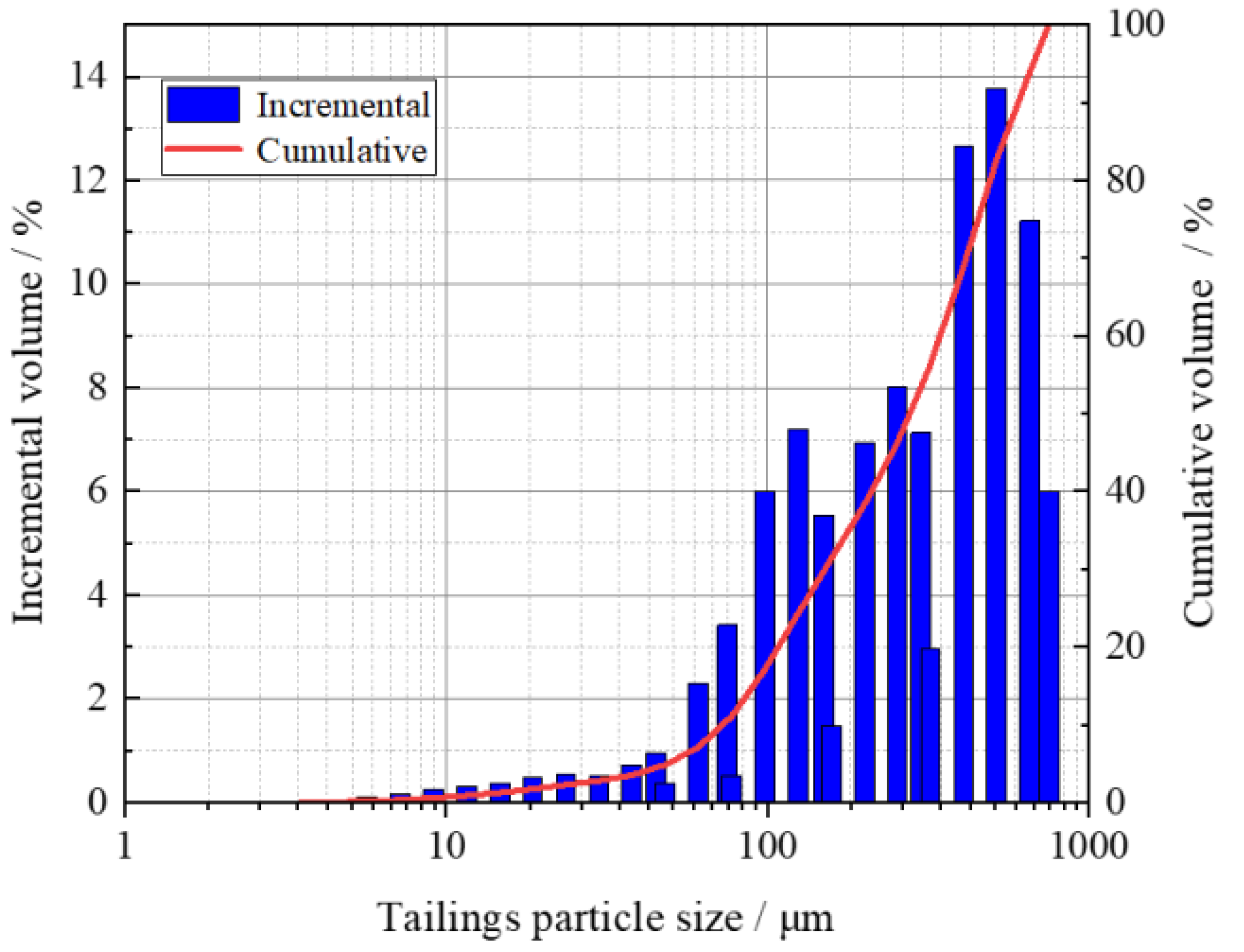
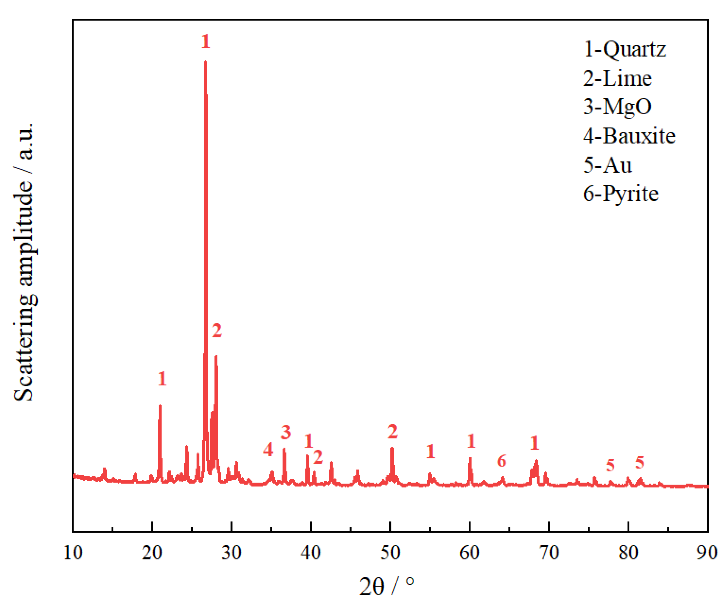
2.1. Material Characterization

The tested unclassified gold tailings used in the study were from a gold mine in the Shandong Gold Group Co., Ltd. The density of the tested tailings was 2.34 g/cm3, and the specific surface area was 39.595 m3/kg. After drying, the tailings were analyzed by a laser particle size analyzer. Figure 1 shows the particle size distribution curve of unclassified tailing. The d50 of unclassified tailing is 321.295 μm, which belongs to larger-sized tailings according to Landriault’s mine tailings classification [30,31]. A sequential X-ray fluorescence spectrometer is used to test the chemical composition of tested tailings and cement. Table 1 shows the chemical composition of the tested tailings. The main component is SiO2, accounting for 58.4 wt.%. Figure 2 shows the X-ray diffraction (XRD) patterns of tested tailings, which agrees well with their chemical components [32]. The tailings mainly consist of crystalline minerals (i.e., quartz and lime).
The ordinary Portland cement 42.5R was used to be the cementing material. The chemical composition is shown in Table 2. Among them, the effective ingredient CaO accounts for 35.4 wt.%.
The water used is tap water.

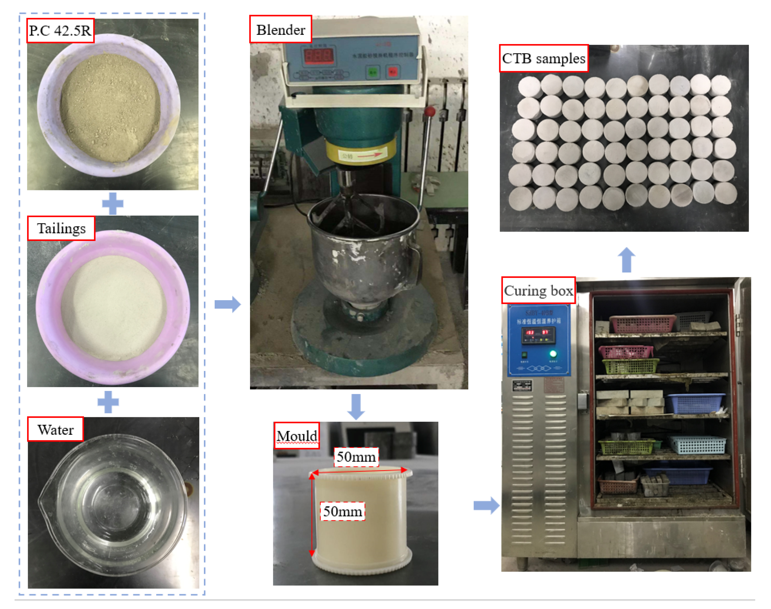
2.2. Specimen Preparation

In this study, the value of solid content and the cement–tailings ratio of the manufactured CTB samples was constantly set to 75 wt.% and 0.25. The experiment personnel used a standard electronic scale to weigh the tailings, cement, and tap water and fully stirred the materials in the mixer for 180 s [33]. The content of each component is 34.5 g of cement, 138 g of tailings, and 57.5 g of water. The slump value of the tested CTB slurry was about 24.5 cm. Then, the stirred slurry was poured into the mold (the mold with a height of 50 mm and a diameter of 50 mm) with the requirements of ASTM C192/C192M [34]. The CTB samples were placed inside the standard curing box at 20 ℃ ± 1 ℃ in temperature, 90% ± 1% in humidity. After 48 h, the samples were demolished from the mold and then returned to the curing box until 28 d [35]. After 28 d, the specimen was gently polished at both ends to meet the flatness requirements of the dynamic load test [36]. The preparation process of CTB specimens is shown in Figure 3.

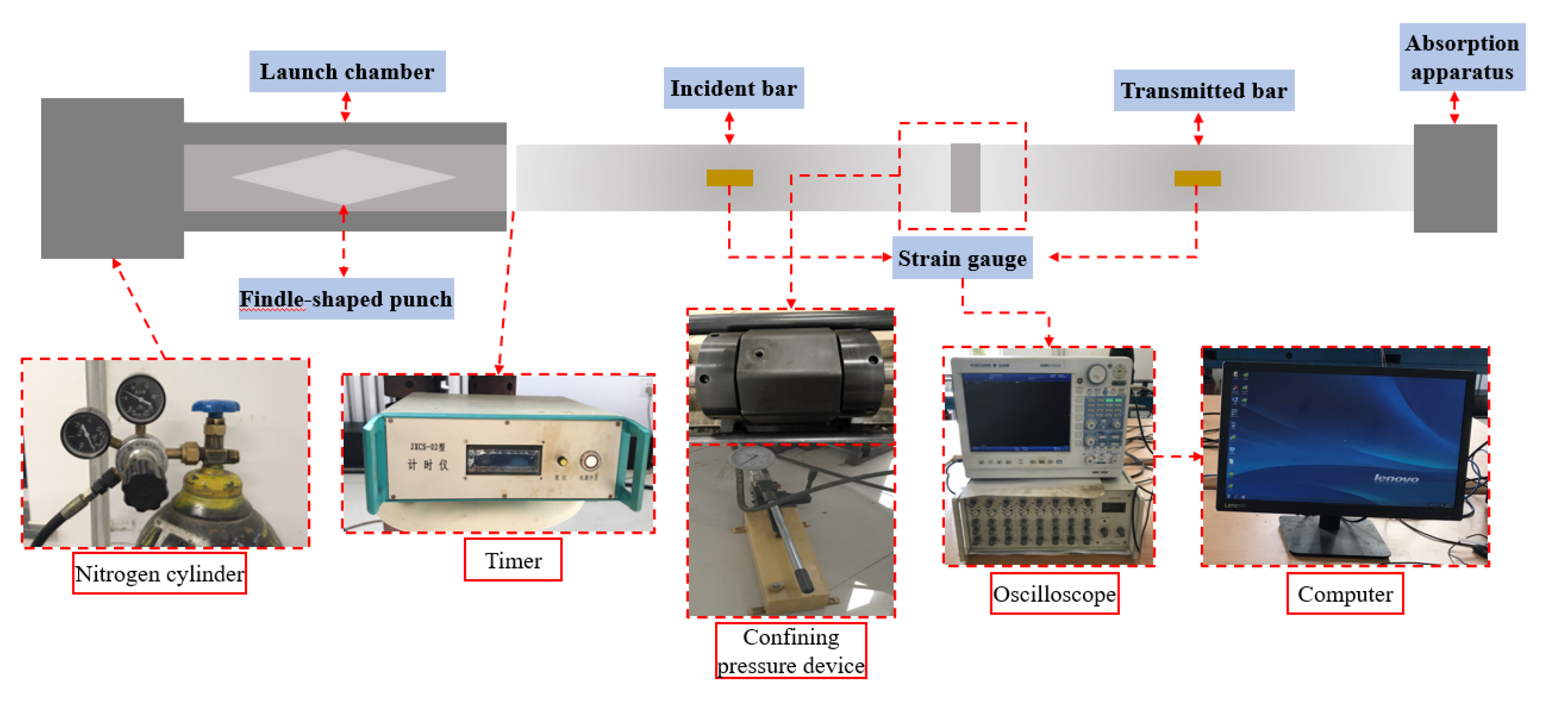
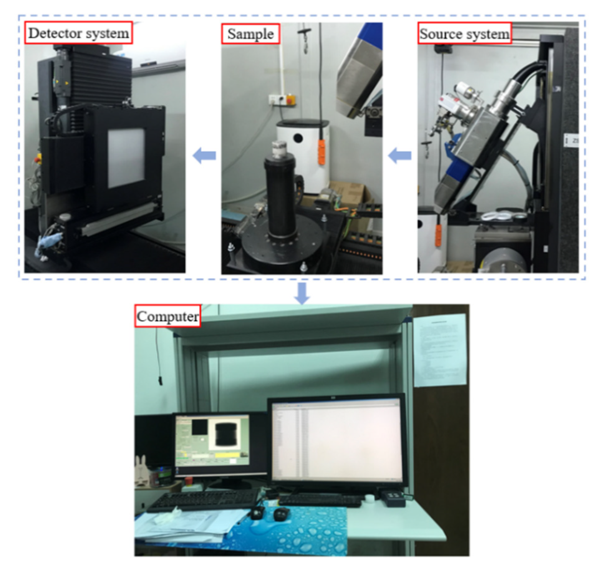
2.3. Experimental Devices

The SHPB test platform consisted of a nitrogen cylinder, Hopkinson pressure bar test bench, launch chamber, elastic pressure bar, confining pressure device, super dynamic strain gauge, oscilloscope, computer, timer, and other parts. The diameter of the pressure bar in the SHPB test device was 50 mm, the material was 40 Cr alloy steel, the density was 7800 kg/m3, and the wave velocity was 5200 m/s. In this study, the maximum average strain rate was 98 s−1. Besides, the sensitivity of the hyper dynamic strain gauge was more than 0.2 V/100 με, and the strain coefficient was 2.0 [37]. Figure 4 is a schematic diagram of the SHPB test device system. Before the beginning of SHPB, a thin layer of Vaseline should be coated on the end surfaces of the specimen to eliminate possible stress that is uneven due to contact between the specimen and bars.
The micro-CT test system used in this study was a dual-source, dual-detector system. The two sources are the 225 kV microfocus and 450 kV light source, whereas the two detectors were a flat panel and line array detector. In this experiment, a 225 kV micro-focus micro-CT light source was used for a continuous rotating scan at a spatial distribution rate of 23 Lp/mm. The exact resolution of the backfill specimen prepared in the experiment was 68 μm. Figure 5 presents a diagram of the CT test system device.

3. Results and Discussion

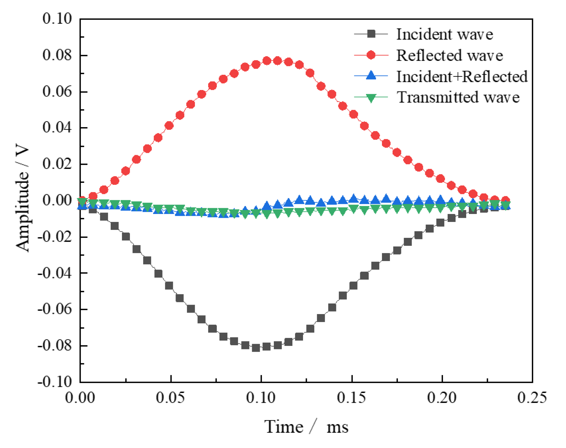
3.1. Dynamic Stress Equilibrium

The assumption condition for establishing the SHPB test system is that it conforms to the one-dimensional stress wave propagation theory and that the two ends of the specimen reach stress equilibrium [38]. Therefore, it is necessary to check the stress equilibrium at both ends of the specimen. When the incident wave plus the reflected wave is approximately equal to the transmitted wave, the two ends of the specimen are said to reach a stressed equilibrium. Figure 6 is a superposition of the waveform relationship of the CTB specimen. The stress at the incident end of the specimen is counted by the incident wave plus the reflected wave, and the stress at the transmitted end is the transmitted wave. The relationship between the stress and time in the pressure bars at both ends of the specimen can be obtained by superposition. As shown in Figure 6, the amplitudes of superimposed wave and transmitted wave are almost equal. The waveforms overlap, indicating that the two ends of the backfill specimen in this experiment have reached a stressed equilibrium.

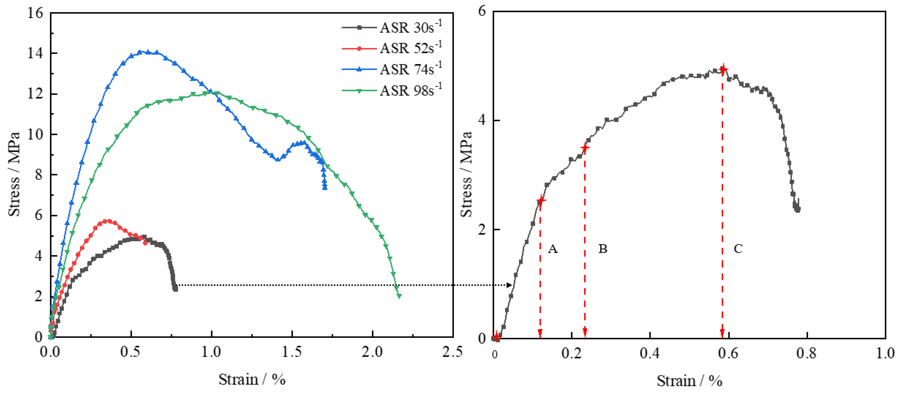
3.2. Relation between Dynamic Stress and Strain

Actually, the dynamical strength enhancement factor obtained in this manuscript could provide a data basis for the engineering application of the strength design of the backfill. As we know, the design of the CTB must consider the safety factor in the actual mining process. CTB samples were performed ASR by SHPB of ASR in the range from 30 to 98 s−1. Figure 6 shows the relationship between the ASR of CTB and DUCS and the dynamic strength enhancement factor. As shown in Figure 6, when the ASR was between 30 and 98 s−1, the DUCS of CTB shows a trend of first increasing and then decreasing with ASR. When the strain rate is 74 s−1, the peak DUCS of CTB is 14.1 MPa. According to the uniaxial compression test, the static uniaxial compressive strength of CTB is 4.47 MPa. In rock dynamics, dynamic strength enhancement factors are often used further to express the strain rate effect [39].
K = σ d σ S
In the equation, K is the dynamic strength enhancement factor, σ d is the peak compressive strength under dynamic load, and σ S is the peak compressive strength under static load. The calculation results are shown in Figure 7.
Figure 8 shows that the relationship between the stress and strain curves of the CTB under different ASR. As shown in Figure 7 and Figure 8, CTB also exhibits a strengthening effect of ASR, consistent with the findings of other scholars [13,16]. However, the difference is that when the ASR is 74 s−1, the strengthening effect of the strain rate decreases. The large wave impedance of CTB may cause this. The height to diameter ratio of the specimen used here is 1, and the height to diameter ratio of the backfill specimen studied by most scholars is 0.5. Hence, when the strain rate is greater than 74 s−1, the strengthening effect of the strain rate decreases.
In this study, the pre-peak mechanical properties of CTB were significantly investigated. The paper also analyzes the pre-peak stress–strain curve of CTB with the ASR of 74 s−1. The stress–strain curve at the OB section is nearly straight. Due to the immediate impact speed, the pore compaction stage of the specimen does not appear, and the stress–strain curve directly enters the elastic deformation stage. When the BC section is at the stage in which the micro-fracture development is stable, the specimen presents micro-fracture and develops steadily, although the stress–strain curve is still almost linear at this point. When the BC section is at the progressive rupture stage, the micro-rupture continues to accumulate and develop until the specimen is completely damaged and reaches the compressive strength of the cemented backfill at the dynamic peak, that is, point C.

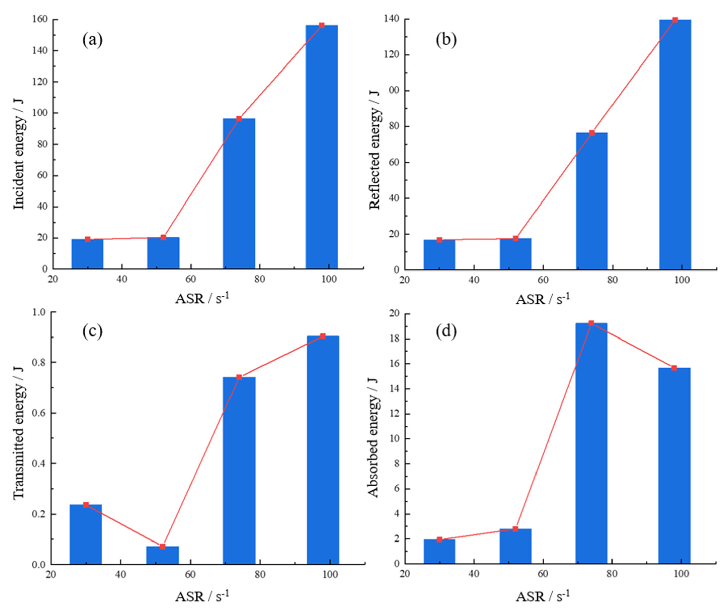
3.3. Energy Dissipation Analysis

The SHPB test was conducted along with the energy dissipation, and the absorbed energy was used for evaluation. The relationships among incident energy W I , reflected energy W R , transmitted energy W T , and absorbed energy W S are given by [39],
W S ( t ) = W I ( t ) W R ( t ) W T ( t )
W I ( t ) = E A C 0 0 T ε I 2 ( t ) d t
W R ( t ) = E A C 0 0 T ε R 2 ( t ) d t
W T ( t ) = E A C 0 0 T ε T 2 ( t ) d t
where E is the elastic modulus of the compression bar, A is the cross-sectional area of the incident bar, C 0 is the velocity of elastic stress wave, ε I is the incident strain, ε R is the reflected strain, and ε T is the transmitted strain. According to the test results. The CTB energy is obtained as shown in Table 3.
Next, the relationship diagram among strain rate and incident energy reflected energy, transmitted energy, and absorbed energy is drawn according to Table 3. It can be seen from Figure 9 that the incident energy of the cemented backfill and the reflected energy both increase as the strain rate increases. As the strain rate increases, the transmitted energy first decreases and then increases. However, transmitted energy is less than 1 J due to the large difference between the density of the cemented backfill and the density of the impact bar and the large difference in wave impedance [16]. This lessens the transmitted wave received in the transmitted bar, making the transmitted energy so little and, thus, negligible. At the same time, the absorbed energy of the cemented backfill shows a trend first increasing and then decreasing with the increase in strain rate. This indicates that the cemented backfill has a better energy absorbed performance, although it may be limited as the energy cannot be absorbed after reaching the peak. The energy-absorbing performance is consistent with its dynamic peak intensity.

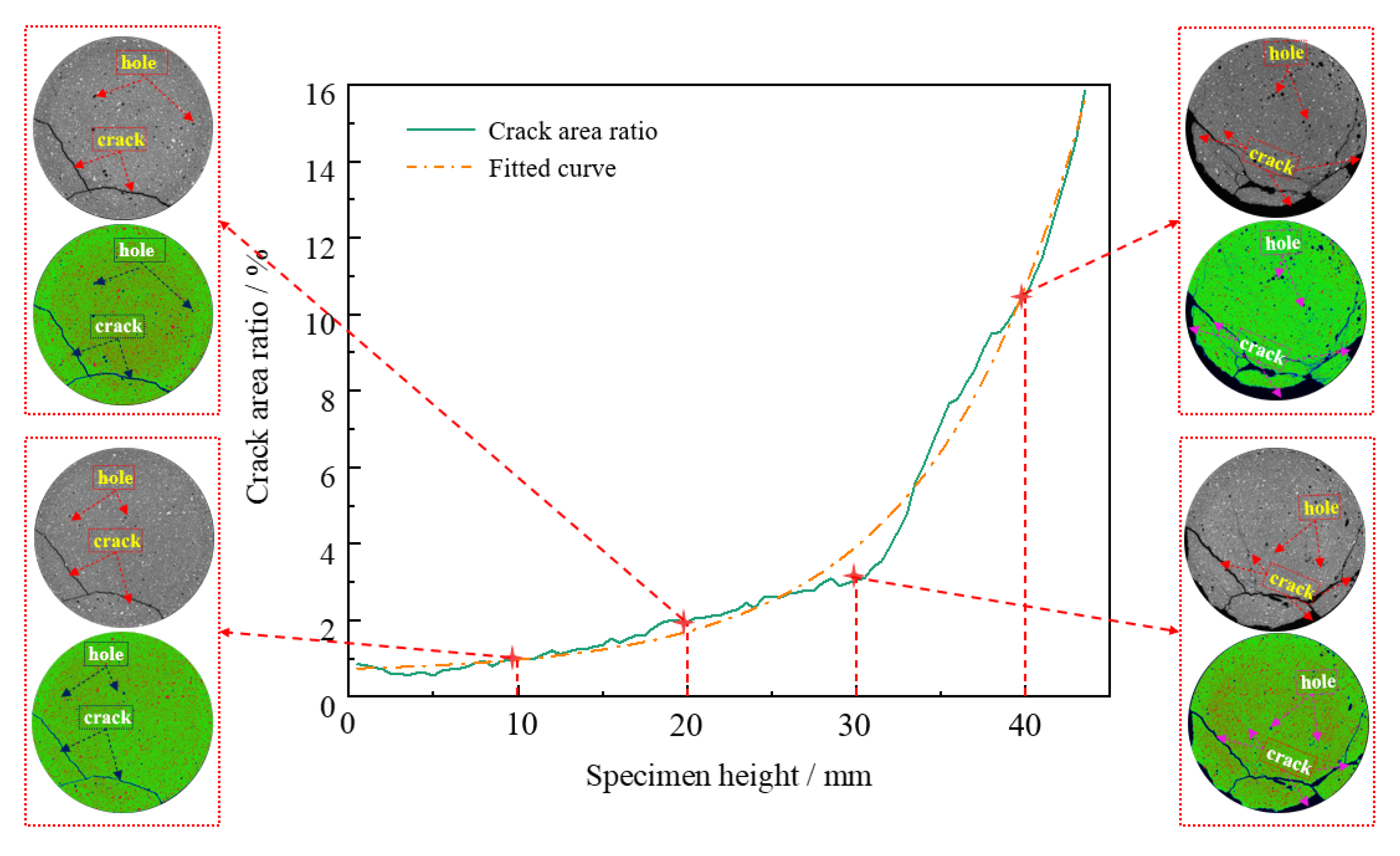
3.4. Two-Dimensional Micros-Crack Distribution of CTB Specimens

The distribution of cracks and pores in the CTB was obtained by micro-CT scanning. When the ASR is 30 s−1, the CTB after dynamic load was generally intact and scanned by micro-CT. The 2D images of the CTB samples were obtained by the slicing function of micro-CT with 0.5 mm spacing along the Z-direction of samples. ImageJ software (V1.8.0, National Institutes of Health, MD, USA) was used to binarize the CT slice images to make the cracks more clearly displayed and then used the analyze particles function to calculate the area ratio of the cracks to the entire slice. Finally, the results are shown in Figure 10. As the specimen’s height increases and the specimen comes closer to the incident bar, the failure area of the specimen increases. Near the incident bar, the failure area of the CTB accounts for about 16% of the total area, whereas the failure area only accounts for about 1% near the transmitted bar. The crack area ratio is exponentially related to the specimen height. The correlation coefficient R2 = 0.989 indicates that the exponential function has a high correlation, and the exponential equation relation is y = a e x b + y 0 , where a , b , and y 0 are constants ( a = 0.12, b = −17.89, y 0 = 0.62).
A slice image was taken every 10 mm for further analysis, as shown in Figure 10. It can be seen that there are initial holes in CTB. A pseudo color-enhancing algorithm was used to process the micro-CT slice images to facilitate image analysis [40,41]. Figure 10 shows that the part of CTB wherein the stress wave acts first (Z = 40 mm) had partly been spalled and had some cracks and micro-cracks. Furthermore (Z = 30 mm), the main cracks and micro-cracks increased when the spalling area of CTB reduced. When Z = 20 mm, the structure of CTB is intact without spalling, and there are two main cracks and one micro-crack. When Z = 10 mm, the structure of CTB is also intact without spalling; although there are two main cracks, no micro-cracks are observed. According to the test results, when the CTB undergoes a different strain rate by Hopkinson dynamic load tests, only 30 s−1 remains basically intact, and the others are impacted into fragments. Overall, it can be seen that when the strain rate is 30 s−1, CTB can maintain a complete shape with residual strength.

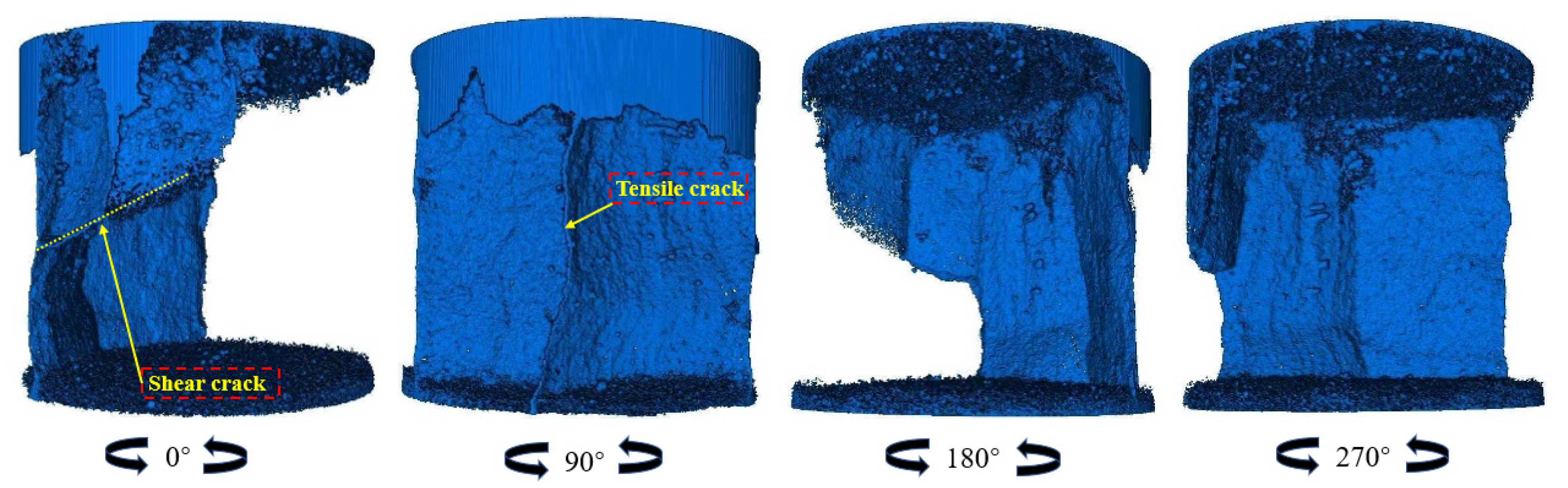
3.5. Failure Modes of CTB Specimens Analysis

The specimen or specimen pieces of the impacted cemented backfill are collected and summarized. The CTB specimen with a strain rate of 30 s−1 remains relatively intact after the impact. Thus, this specimen was selected for micro-CT scanning, and other specimen pieces were flattened and photographed into pictures. The pictures underwent grey-scale binarization processing. Table 4 shows the diagrams of each cemented backfill that is damaged under different strain rates. In this section, the maximum block size of CTB was used to assess the failure degree. With the increase in the ASR from 54 to 98, the maximum block size of the CTB specimen decreased from 25 to 17 mm.
A slice picture was obtained every 0.5 mm using CT scan, and slice image data reconstructed the damaged cemented backfill. The results are shown in Table 4. Distinctly, at an ASR of 30 s−1, CTB can still maintain a relatively intact shape. The entire surface of the specimen shows tensile cracks. With the increase in ASR, it is obvious that the rate of large blocks decreases, and the rate of small blocks increases after the cemented backfill is damaged.
The specimen under dynamic load with the ASR of 30 s−1 was used for three-dimensional reconstruction of the crack. Figure 11 shows the different angles of the three-dimensional reconstruction of the crack of the specimen. Obviously, when the ASR is 30 s−1, the transfixion crack of CTB is a tensile crack accompanied by a shear crack on the surface. Actually, the phenomenon of CTB or CPB failure was prone to occurring in pillar mining, such as the fragmentation and collapse of artificial CTB pillars. In addition, the deformation of the CTB or CPB in the downhand cut and fill mining method was also a typical type of tensile failure.

4. Conclusions

In this paper, a series of laboratory tests, including the SHPB test, energy dissipation, and micro-CT scan, was conducted on CTB specimens to explore their dynamical mechanics and microstructural characteristics. The conclusions are as follows:
(1)
In the SHPB test, the superimposed wave of the incident wave and reflected wave was almost equal to the amplitude of the transmitted wave, and the waveforms overlapped. The two ends of the CTB specimen in this experiment reached a stressed equilibrium.
(2)
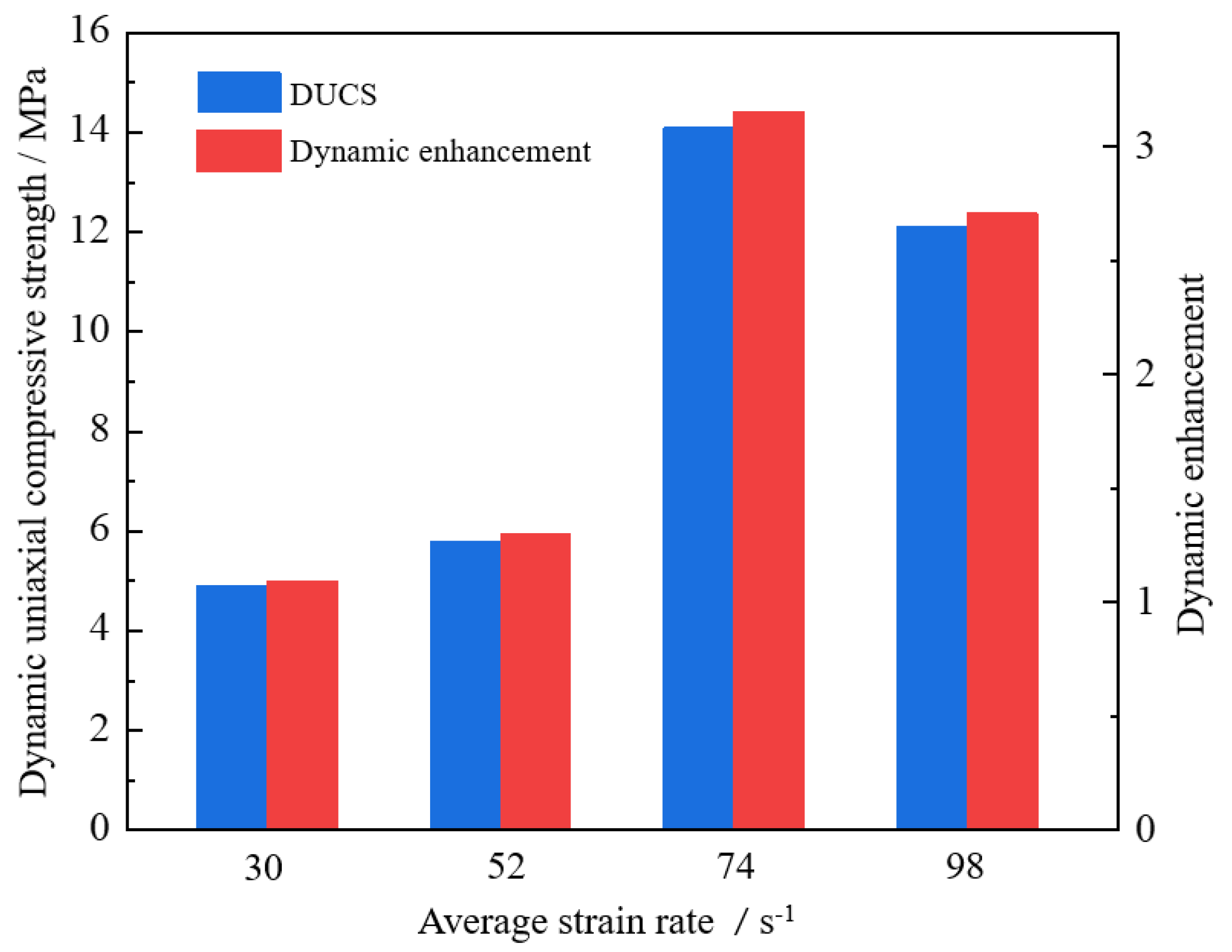
When the ASR is 30–98 s−1, with the increase in the ASR, the DUCS of the CTB shows a trend of first increasing and then decreasing.
(3)
The CTB also exhibits a strengthening effect of strain rate, and when the ASR is greater than 74 s−1, the strengthening effect decreases.
(4)
As the ASR increases, the incident energy of the CTB increases, and the reflected energy also increases. The transmitted energy can be negligible, and the absorbed energy shows a trend of first increasing and then decreasing, which is consistent with its dynamic peak intensity.
(5)
The pseudo-color enhancement was carried out for the original CT slice image with micro-CT. Results show that the closer the specimen near the incident bar, the larger the crack area of the specimen. The crack area ratio is exponentially related to the specimen height.
In this study, the research finding has revealed the dynamical mechanics and microstructural characteristics of CTB. In future work, the further dynamic energy dissipation analysis of CTB will be considered. Additionally, the SHPB experiments with 3D-DIC techniques will be considered to observe the real progress of the crack development of CTB.

Author Contributions

Conceptualization, W.S. and S.C.; methodology, D.Z.; writing—original draft preparation, D.Z.; writing—review and editing and supervision, D.Z., J.L. and S.C.; funding acquisition, W.S., L.S. and S.C. All authors have read and agreed to the published version of the manuscript.

Funding

This research was funded by the National Natural Science Foundation of China (grant numbers 51804017 and 51974012), the Opening Fund of State Key Laboratory of Nonlinear Mechanics (grant number LNM202009), and the Fundamental Research Funds for Central Universities (grant number FRF-TP-20-001A2).

Data Availability Statement

No applicable.

Acknowledgments

The authors thank Shandong Gold Group Co. for the test tailings. Thanks to the School of Mining Engineering, North China University of Science and Technology for providing the SHPB test equipment, and special thanks to Liu and Tian for their guidance and help in the test.

Conflicts of Interest

The authors declare no conflict of interest.

References

  1. Qin, J.; Zheng, J.; Li, L. Experimental study of the shrinkage behavior of cemented paste backfill. J. Rock Mech. Geotech. Eng. 2021. [Google Scholar] [CrossRef]
  2. Keita, A.M.T.; Jahanbakhshzadeh, A.; Li, L. Numerical analysis of the stability of arched sill mats made of cemented backfill. Int. J. Rock Mech. Min. 2021, 140, 104667. [Google Scholar] [CrossRef]
  3. Jiang, L.; Su, Y.; Dai, Q. Dynamic response mechanisms of layered cemented backfill pillars under horizontal stress wave disturbance of far-field blasting. Chin. J. Rock Mech. Eng. 2020, 39. [Google Scholar] [CrossRef]
  4. Wu, D.; Zhao, R.; Xie, C.; Liu, S. Effect of curing humidity on performance of cemented paste backfill. Int. J. Miner. Metall. Mater. 2020, 27, 1046–1053. [Google Scholar] [CrossRef]
  5. Zhang, J.; Deng, H.; Taheri, A.; Deng, J.; Ke, B. Effects of Superplasticizer on the Hydration, Consistency, and Strength Development of Cemented Paste Backfill. Minerals 2018, 8, 381. [Google Scholar] [CrossRef] [Green Version]
  6. Tang, Y.; Zheng, J.; Guo, L.; Zhao, Y. Effect of Gypsum Addition on the Mechanical and Microstructural Performance of Sulphide-Rich Cemented Paste Backfill. Minerals 2021, 11, 283. [Google Scholar] [CrossRef]
  7. Wang, J.; Fu, J.; Song, W.; Zhang, Y. Viscosity and Strength Properties of Cemented Tailings Backfill with Fly Ash and Its Strength Predicted. Minerals 2021, 11, 78. [Google Scholar] [CrossRef]
  8. Xu, W.; Cao, P.; Tian, M. Strength Development and Microstructure Evolution of Cemented Tailings Backfill Containing Different Binder Types and Contents. Minerals 2018, 8, 167. [Google Scholar] [CrossRef] [Green Version]
  9. Wu, J.; Feng, M.; Chen, Z.; Mao, X.; Han, G.; Wang, Y. Particle Size Distribution Effects on the Strength Characteristic of Cemented Paste Backfill. Minerals 2018, 8, 322. [Google Scholar] [CrossRef] [Green Version]
  10. Cao, S.; Yilmaz, E.; Song, W. Dynamic response of cement-tailings matrix composites under SHPB compression load. Constr. Build. Mater. 2018, 186, 892–903. [Google Scholar] [CrossRef]
  11. Cao, S.; Yilmaz, E.; Song, W. Evaluation of Viscosity, Strength and Microstructural Properties of Cemented Tailings Backfill. Minerals 2018, 8, 352. [Google Scholar] [CrossRef] [Green Version]
  12. Zhu, P.; Song, W.; Xu, L.; Wang, J.; Wan, F. A study on mechanical properties of cemented backfills under impact compressive loading. J. Vib. Shock. 2018, 37, 131–137. [Google Scholar]
  13. Tan, Y.; Wang, J.; Song, W.; Xu, L.; Cao, S. Experimental study on mechanical properties of cemented tailings backfill under cycle dynamic loading test. J. Min. Saf. Eng. 2019, 36, 184–190. [Google Scholar]
  14. Tan, Y.; Yu, X.; Elmo, D.; Xu, L.; Song, W. Experimental study on dynamic mechanical property of cemented tailings backfill under SHPB impact loading. Int. J. Miner. Metall. Mater. 2019, 26, 404–416. [Google Scholar] [CrossRef]
  15. Tan, Y.; Davide, E.; Zhou, Y.; Song, W.; Meng, X. Long-term mechanical behavior and characteristics of cemented tailings backfill through impact loading. Int. J. Miner. Metall. Mater. 2020, 27, 140–151. [Google Scholar] [CrossRef]
  16. Yang, W.; Tao, M.; Li, X.; Li, G. Mechanical Properties of the Total Tailing Cemented Backfilling Impacted by Cement-Sand Ratio Under High Strain Rate. J. Northeast. Univ. Nat. Sci. 2017, 38, 1659–1663. [Google Scholar]
  17. Yang, W.; Zhang, Q.; Yang, S.; Wang, X. Mechanical property of high concentration total tailing cemented backfilling under dynamic loading. J. Cent. South Univ. Sci. Technol. 2017, 48, 156–161. [Google Scholar]
  18. Wang, J.; Fu, Y.; Hou, Y.; Yang, M.; Zhang, J. Research on the Dynamic Load Impact Damage of Tailings Filling Bodies with Different Mixture Ratios. Min. Res. Dev. 2017, 37, 8–13. [Google Scholar]
  19. Yang, Q. Experimental Study on Mechanical Properties of Cemented Backfill under Impact. Mod. Min. 2019, 35, 84–86. [Google Scholar]
  20. Cao, S.; Yilmaz, E.; Song, W.; Yilmaz, E.; Xue, G. Loading rate effect on uniaxial compressive strength behavior and acoustic emission properties of cemented tailings backfill. Constr. Build. Mater. 2019, 213, 313–324. [Google Scholar] [CrossRef]
  21. Zhang, Y.; Wang, X.; Wei, C.; Zhang, Q. Dynamic mechanical properties and instability behavior of layered backfill under intermediate strain rates. T. Nonferr. Metal. Soc. 2017, 27, 1608–1617. [Google Scholar] [CrossRef]
  22. Zhang, Q.; Yang, W.; Yang, S.; Wang, X. Test research on the stability of high-density total tailing cemented backfilling under dynamic loading. China Saf. Sci. J. 2015, 25, 78–82. [Google Scholar]
  23. Yin, S.; Chen, X.; Yan, R.; Wang, L. Pore Structure Characterization of Undisturbed Weathered Crust Elution-Deposited Rare Earth Ore Based on X-ray Micro-CT Scanning. Minerals 2021, 11, 236. [Google Scholar] [CrossRef]
  24. Sun, W.; Wu, A.; Hou, K.; Yang, Y.; Liu, L.; Wen, Y. Real-time observation of meso-fracture process in backfill body during mine subsidence using X-ray CT under uniaxial compressive conditions. Constr. Build. Mater. 2016, 113, 153–162. [Google Scholar] [CrossRef]
  25. Sun, W.; Hou, K.; Yang, Z.; Wen, Y. X-ray CT three-dimensional reconstruction and discrete element analysis of the cement paste backfill pore structure under uniaxial compression. Constr. Build. Mater. 2017, 138, 69–78. [Google Scholar] [CrossRef]
  26. Wang, J.; Fu, J.; Song, W. Mechanical properties and microstructure of layered cemented paste backfill under triaxial cyclic loading and unloading. Constr. Build. Mater. 2020, 257, 119540. [Google Scholar] [CrossRef]
  27. Cao, S.; Yilmaz, E.; Yin, Z.; Xue, G.; Song, W.; Sun, L. CT scanning of internal crack mechanism and strength behavior of cement-fiber tailings matrix composites. Cem. Concr. Compos. 2020. [Google Scholar] [CrossRef]
  28. Xue, G.; Yilmaz, E.; Song, W.; Cao, S. Analysis of internal structure behavior of fiber reinforced cement-tailings matrix composites through X-ray computed tomography. Compos. Part B 2019, 175, 107091. [Google Scholar] [CrossRef]
  29. Yi, X.; Liu, C.; Wang, Y. Experimental study on the fracture evolution of cemented waste rock-tailings backfill (CWRB) of metal ore using in-situ CT scanning. Rock Soil Mech. 2020, 41, 3365–3373. [Google Scholar]
  30. Yang, L.; Xu, W.; Yilmaz, E.; Wang, Q.; Qiu, J. A combined experimental and numerical study on the triaxial and dynamic compression behavior of cemented tailings backfill. Eng. Struct. 2020, 219, 110957. [Google Scholar] [CrossRef]
  31. Hao, Y.; Hao, H. Numerical Investigation of the Dynamic Compressive Behaviour of Rock Materials at High Strain Rate. Rock Mech. Rock Eng. 2013, 46, 373–388. [Google Scholar] [CrossRef]
  32. Zhang, S.; Yang, L.; Ren, F.; Qiu, J.; Ding, H. Rheological and mechanical properties of cemented foam backfill: Effect of mineral admixture type and dosage. Cem. Concr. Compos. 2020, 112, 103689. [Google Scholar] [CrossRef]
  33. Huang, Z.; Yilmaz, E.; Cao, S. Analysis of Strength and Microstructural Characteristics of Mine Backfills Containing Fly Ash and Desulfurized Gypsum. Minerals 2021, 11, 409. [Google Scholar] [CrossRef]
  34. Gerges, N.N.; Issa, C.A.; Fawaz, S. Effect of construction joints on the splitting tensile strength of concrete. Case Stud. Constr. Mater. 2015, 3, 83–91. [Google Scholar] [CrossRef] [Green Version]
  35. Xue, G.; Yilmaz, E.; Song, W.; Cao, S. Compressive Strength Characteristics of Cemented Tailings Backfill with Alkali-Activated Slag. Appl. Sci. 2018, 8, 1537. [Google Scholar] [CrossRef] [Green Version]
  36. Xue, G.; Yilmaz, E.; Feng, G.; Cao, S.; Sun, L. Reinforcement effect of polypropylene fiber on dynamic properties of cemented tailings backfill under SHPB impact loading. Constr. Build. Mater. 2021, 279, 122417. [Google Scholar] [CrossRef]
  37. Liu, Z.; Gan, D.; Gan, Z. Dynamic regimes of cemented backfill at early-age. J. Cent. South Univ. 2021, 1–13. Available online: http://kns.cnki.net/kcms/detail/43.1516.TB.20210308.1618.016.html (accessed on 24 April 2021).
  38. Qiu, J.; Li, D.; Li, X. Dynamic failure of a phyllite with a low degree of metamorphism under impact Brazilian test. Int. J. Rock Mech. Min. 2017, 94, 10–17. [Google Scholar] [CrossRef]
  39. Gong, F.; Wang, J.; Li, X. The rate effect of compression characteristics and a unified model of the dynamic increasing factor for rock materials. Chin. J. Rock mech. Eng. 2018, 37, 1586–1595. [Google Scholar]
  40. Chen, X.; Shi, X.; Zhou, J.; Li, E.; Qiu, P.; Gou, Y. High strain rate compressive strength behavior of cemented paste backfill using split Hopkinson pressure bar. Int. J. Min. Sci. Technol. 2021. [Google Scholar] [CrossRef]
  41. Cao, S.; Zheng, D.; Yilmaz, E.; Yin, Z.; Xue, G.; Yang, F. Strength development and microstructure characteristic of artificial concrete pillar considering fiber type and content effects. Constr. Build. Mater. 2020, 256, 119408. [Google Scholar] [CrossRef]
Figure 1. Characteristics of particle size distribution of tested tailings.
Minerals 11 00542 g001
Figure 2. XRD patterns of tested tailings.
Minerals 11 00542 g002
Figure 3. Preparation process of CTB specimens.
Minerals 11 00542 g003
Figure 4. Schematic diagram of the SHPB device.
Minerals 11 00542 g004
Figure 5. Diagram of micro-CT test system device.
Minerals 11 00542 g005
Figure 6. Stress equilibrium.
Minerals 11 00542 g006
Figure 7. Relationship between ASR of CTB and DUCS and the dynamic strength enhancement factor.
Minerals 11 00542 g007
Figure 8. Dynamic stress–strain curve of CTB under different ASR.
Minerals 11 00542 g008
Figure 9. Diagram of energy change in the cemented backfill under different strain rates.
Minerals 11 00542 g009
Figure 10. Crack area distribution along Z-axis.
Minerals 11 00542 g010
Figure 11. Three-dimensional reconstruction of the crack of CTB with ASR of 30 s−1.
Minerals 11 00542 g011
Table 1. Chemical composition of the unclassified tailings.
Chemical CompositionSiO2Al2O3K2OCaOFe2O3SO3MnO
Content (wt.%)58.47.034.022.081.290.70.041
Table 2. Chemical composition of ordinary Portland cement 42.5R.
Chemical CompositionCaOSiO2SO3Al2O3Fe2O3TiO2K2OMnO
Content (wt.%)35.417.13.212.392.190.560.440.1
Table 3. Summary of the energy of CTB.
Specimen No.ASR W I W R W T W S
13018.9916.820.241.93
25220.3417.470.072.79
37496.4676.490.7419.23
498156.22139.640.9015.68
Table 4. Fracture modes of CTB specimens under SHPB impact loading.
ASR/s−130527498
Minerals 11 00542 i001 Minerals 11 00542 i002 Minerals 11 00542 i003 Minerals 11 00542 i004
Minerals 11 00542 i005 Minerals 11 00542 i006 Minerals 11 00542 i007 Minerals 11 00542 i008
Publisher’s Note: MDPI stays neutral with regard to jurisdictional claims in published maps and institutional affiliations.

