Article

Unusual Perforations in Phlogopite Crystals from Caldara di Manziana (Italy) Caused by Sulphuric Acid Generated by Microbial Oxidation of H2S Emanations

1
Department of Life Sciences, Natural History Museum, Cromwell Road, London SW7 5BD, UK
2
Institute for Biological Systems, Council of National Research of Italy (CNR), Area della Ricerca di Roma 1, via Salaria Km 29,300, Monterotondo, 00015 Rome, Italy
3
Department of Earth Sciences, Natural History Museum, Cromwell Road, London SW7 5BD, UK
*
Author to whom correspondence should be addressed.
Submission received: 19 April 2021 / Revised: 15 May 2021 / Accepted: 18 May 2021 / Published: 20 May 2021
(This article belongs to the Special Issue Clay Minerals–Life Interplay)

Abstract

:
Phlogopite flakes strewn on the soil of Caldara di Manziana (Italy) display multiple minute perforations. The site is a caldera linked to recent volcanism (90 ka to 0.8 Ma) with present emanations of CO2 (~150 t d−1) and H2S (~2.55 t d−1). Stereomicroscopy and SEM–EDX observation of the phlogopite crystals shows holes and depressions <200 µm to 2 mm across. They are circular, pseudo-hexagonal, or irregular. Within the depressions, there are deposits of phlogopite alteration products consistent with a sulphuric acid attack, showing loss of Mg and K. Some are thin and homogeneous; others are thick, irregular, and chemically heterogeneous, including plates, flakes, tubes of Fe-beidellite or Fe-bearing halloysite, silica, Fe oxides, and gypsum. Areas of phlogopite surface are also altered. Sulphuric acid is produced from the H2S gas by the mediation of sulphur-oxidizing bacteria. Pseudo-hexagonal perforations are interpreted to result from slow acid attack with dissolution controlled by phlogopite crystal symmetry. Some depressions developed surrounding films of pseudo-hexagonal shape, interpreted as jarosite crystallizing radially outwards from the depressions. This style of acid attack is possibly promoted by local high humidity and precipitation that generate long-lived water droplets and films on mineral surfaces where sulphuric acid is active for prolonged times.

1. Introduction

Manziana (near Rome, Italy) is a volcanic area that features “Caldara di Manziana”, a protected natural area (coded as a SIC, IT6030009, in 2006/613/CE). The park is named after the Caldara di Manziana (42°05′11.8″ N 12°06′05.5″ E; Figure S1: location and geological maps), a subcircular structure of 0.25 km2, possibly generated by a hydrothermal explosion [1] during the alkali-potassic volcanism affecting central Italy from 0.8–0.6 Ma to 90 ka [2]. The rocks correspond to the Volcanic Sabatini District, and they are mainly explosive, pyroclastic deposits, and some lava flows. The rocks consist mainly of undersaturated ultrapotassic rocks ranging from tephrite to phonolite, with some trachytes and latites erupted locally. The rock texture is porphyritic with 5–40% volume of phenocrysts. Abundant phenocryst phases are clinopyroxene, olivine, plagioclase and Fe-Ti oxides. Phlogopite phenocrysts are rare. The groundmass contains leucite, clinopyroxene, K-feldspar, plagioclase, glass, sporadic phlogopite, and amphibole. Apatite is also found in the groundmass [2].
The rocks of the Volcanic Sabatini District overlay acid volcanics of the Tolfa-Manziana-Cerite complex of the Tuscany province, which correspond to older volcanic episodes 3.7 to 1.8 Ma old [3]. Although the older complex includes the name of Manziana, it is the younger volcanics (Volcanic Sabatini District, 0.8–0.6 Ma to 90 ka old) that are of interest here.
The caldera floor sustains a constant, focused, and diffuse CO2 flow that does not allow the growth of vegetation [1,4]. The CO2 flux in the unvegetated area was 160 t d−1 in July 1996 [5]. The CO2 originates from a deep (~2000 m) geothermal reservoir within Mesozoic carbonates with an estimated temperature of ~200 °C, and interacts with superficial aquifers before reaching the surface, where fluids are at 9–15 °C [6]. In the approximate centre of the area of diffuse CO2 venting there is a permanent pool of water (~10 m diameter, ~0.5 m deep) caused by the focused rising and expulsion of CO2 [4]. The focused venting of CO2 generates a permanent geyser ~1 m wide and ~75 cm high. The water from this pool and from several other smaller sources within the caldera form little streams that join together and run in the south-west direction. Again, all of these water sources have temperatures in the range of 9–15 °C. In the winter, the centre of the caldera becomes flooded and water is seen to bubble [4]. Moreover, the caldera floor is an H2S source with a diffuse, spatially variable flux (from 0.037 to > 132 g m−2 d−1) with a total output of 2.55 t d−1, as measured in 2007 [6]. When the caldera is flooded in the winter, much of the H2S venting occurs through the sheet of water and part of the gas dissolves in the water. The pH in water sources, pools, and streams ranges between slightly and strongly acidic (just below 7 to 1). Other gasses detected, in minor or trace concentrations, are N2, Ar, CH4, H2, He, and CO [6]. The H2S emissions have caused the precipitation of sulphur as well as the acidic alteration of the local volcanics with the generation of halloysite and amorphous silica in the caldera itself and in the Solfatara di Manziana, another area of H2S exhalation ~3.6 km northeast of the Caldara di Manziana [7]. Solfatara di Manziana (42°07′03.7″ N 12°07′22.2″ E) is an abandoned sulphur mine. Both sulphur precipitation and extensive acid alteration (the action of sulphuric acid) require the oxidation of S in the H2S gas dissolved in water. The fastest route for these oxidation reactions is by the action of sulphur-oxidizing bacteria, to the point that purely inorganic routes contribute insignificantly to this process in moist and S-rich soils, such as those in Caldara di Manziana [8].
Phlogopite chips were collected close to Caldara di Manziana with the purpose to use well developed, macroscopic crystals for the in vitro investigation of the interaction of microbial fungi with minerals [9]. A few hornblende crystals were also found and collected.
Many of the collected phlogopite crystals had an interesting feature. The crystals had numerous holes (10–20 could be discerned in individual crystals examined carefully) of variable shapes and sizes (Figure 1). This phenomenon has not yet been described. Here, we present an investigation of these structures and a model of their formation and related mineral and chemical processes.

2. Methods

2.1. Stereomicroscopy

The minerals were observed with a stereoscopic microscope (Leica MZ16, Leica Microsystems GmbH, Wetzlar, Germany) fitted with low temperature fibre optic lighting and a digital camera connected to software that allowed composition of multifocal images (Leica Application Suite, LAS, Leica Microsystems GmbH, Wetzlar, Germany).

2.2. Electron Microscopy with Micro-Analysis

The flakes of phlogopite were first examined uncoated using an EVO50 variable pressure SEM (Carl Zeiss AG, Jena, Germany) equipped with detectors for backscattered electrons (BSE) and secondary electrons (SE). The crystals were reversibly glued to double-side sulphur-free adhesive carbon tape (Spectrotabs AGG3358, Agar Scientific Ltd., Stansted, Essex, UK) and attached onto an Al stub (1.25 cm diameter, Agar Scientific). Both sides of the crystals were examined. A second series of analysis were conducted in high vacuum mode with a Zeiss Ultra Plus Field Emission SEM (Carl Zeiss AG, Jena, Germany) for high-resolution imaging of samples after carbon coating (Cressington Sputter Coater, 208 HR, Cressington Scientific Instruments, Watford, UK). Chemical analysis was performed by means of an INCA EDX 250 detector (Oxford Instruments NanoAnalysis & Asylum Research, High Wycombe, UK) fitted on the EVO50 SEM, and of an Oxford X-Max EDX detector working with the Zeiss Ultra Plus Field Emission microscope.
The EVO50 SEM was fitted with a tungsten filament and operated at 20 keV, with an average working distance of 12.5 mm, with a chamber pressure of about 30 Pa. The electron beam current was adjusted (~400 Pa) to generate sufficient X-rays to allow reliable identification of EDX peaks, minimize spectral artefacts, and achieve detector dead times <20%. The EDX data acquisition with the Zeiss Ultra Plus microscope was carried out at high vacuum (~10−5 Pa). Analyses were performed at 20 kV and 40 s of EDX acquisition time with <12% dead time. Most measurements consisted of point analyses. In some areas of apparently clean and uniform phlogopite, area analyses (a few μm across) were performed. Conventional ZAF correction (for atomic number Z, absorption and fluorescence) was applied, integrated into the microanalysis software [10]. Because analyses were not corrected using results from mineral standards, they cannot be considered fully quantitative.
The EDX data were used to investigate the nature of the processes that had produced the holes in phlogopite. Such processes should have controlled the chemical composition of any debris deposited on phlogopite as a result of their action. Chemical compositions could identify the nature of some mineral phases, while atomic ratios and correlations would establish whether or not they were related to phlogopite and, if so, the chemical path that produced them.

3. Results

3.1. Phlogopite Crystals with Holes and Depressions on the Surface

The phlogopite crystals are up to 2 cm in lateral size, from brown to black as their thickness increases, which may reach up to 2 mm. Many crystals are fairly clean but others have adherences that may have originated from the alteration of phlogopite itself or from other minerals in the soil. Some of the crystals have holes with shapes that range from near circular to elongated, with curved and straight sides, to approximately hexagonal (Figure 1). The size of the holes is also variable, from nearly 1 mm of diameter to <200 µm. Some of these holes do not perforate the entire crystal, but terminate on a flat surface (Figure 1b,c and Figure 2a–c). When this is the case, there are descending steps from the external surface of the crystal towards the bottom of the cavity (Figure 1c and Figure 2c). Such steps also exist in cavities penetrating the entire crystal, in which case they are typically narrower (Figure 1b and Figure 2d). For the sake of simplicity we will refer to the structures not piercing the entire phlogopite crystal as “depressions”. The structures that pierce the entire crystal will be called “holes”.
All depressions contain some sort of sediment within them. In some cases, this sediment is thin and confined to the depression or hole so that the surrounding phlogopite surface is clean (Figure 1c and Figure 2a–c,e). The same material is also present in the steps of holes (Figure 2d). In many other cases, the material filling depressions and on the steps of holes is very abundant and can also be found on the phlogopite surface surrounding the depression or hole (Figure 1d–f). In these cases, it is not obvious whether the material was formed within the structures and then spilled outside them, or it formed elsewhere, and came to fill or coat the walls of depressions or holes.
The SEM–EDX investigation of the thin sediment coating steps in depressions and holes indicated that it was fine-grained, with a particle size typically <2 µm and few larger particles (Figure 2c–f). This material formed a thin layer that draped the topography below (Figure 2c–f). In some cases, the coating layer disappeared and the underlying phlogopite was revealed (Figure 2d,e). At the very edge of some depressions, it was possible to observe a rim in the coating that appeared to be produced by a different orientation of the particles, parallel to the vertical wall of the step (Figure 2e). This rim was not observed at the edges of steps within depressions, supposedly because this structure was covered with coating material developing horizontally.
The chemical analyses of clean areas surrounding holes and depressions showed a fresh phlogopite composition (Figure 3d1), as did phlogopite surfaces in steps within holes and depressions that lost the coating (Figure 3d3). The chemical composition of the coating was relatively homogeneous and corresponded to the alteration of the phlogopite towards a dioctahedral phyllosilicate with lower Mg and K contents (Figure 3d2,e1,e3). Given the thinness of the coating, it could be possible that their EDX analyses were contaminated by the phlogopite below. A rough assessment of this possibility was carried out considering the thickness of the coating rim at the edge of the depression in Figure 2e, which was ~3 µm. Assuming that this thickness is representative of the coating elsewhere in this depression and in other structures, the EDX analyses of the coating were probably free from contamination of the phlogopite underneath.
In some places within the coating, there were elongated particles with light contrast (Figure 2g) that resolved into bundles of needles when observed at higher magnification (Figure 2h). The light contrast indicated a different composition from the coating. No EDX analysis could be performed on these needles exclusively, and all the corresponding EDX results included the composition of the coating in the background. However, it is obvious that the needles were composed of P, Ca, La, Ce, and Nd (Figure 3h1,h2). This suggests phosphates of the apatite and monazite groups, perhaps with substitutions (Ce and Nd in apatite, Ca in monazite) [11,12].
Besides the clear-cut holes and depressions described above, with thin coatings of altered phlogopite, there were other structures that contained large amounts of alteration products and these alteration products were most commonly also found outside these structures. The shapes of the perforation structures varied, from irregular (Figure 4a,g), round with steps (Figure 4c,e), slightly elongated (depression on the left in Figure 4g), and a trough ending in an elongated depression with steps (Figure 4i,j; the image in i does not show the entire structure). Several of these structures suggest the advance of a corroding fluid (Figure 4a,g,j). Detailed images show the morphology and composition of the alteration products. There were plates (Figure 4b) with a composition indicating altered phlogopite (Figure 5b1), mixed with a mesh of tubular structures with a composition suggesting Fe,K-beidellite (Figure 5b2). The morphology and composition of plates and tubes suggest two progressing stages of alteration of phlogopite towards a Si-Al phase. A different morphology was found in other depressions consisting of an abundant, uneven precipitate forming bubble-like structures in which layers of different contrasts appeared (Figure 4c,d, which is the same depression shown in Figure 1f, with an orange precipitate; Figure 4g: uneven sediment appears on the right and within the elongated depression on the left). Frequently, such areas were especially rich in Fe (Figure 5d1). The bubble-shaped precipitate presented layers of different contrast (arrows in Figure 4d), probably representing layers with different silicate/Fe-oxide ratios. On other occasions, however, the bubble-shaped precipitate consisted mainly of Si, and in these cases, sections of the precipitate showed small or no layer contrast (not shown). In some areas of the precipitate there were small grains of gypsum (Figure 4d and Figure 5d2).
A more frequent type of abundant precipitate consisted largely of a silicate sediment in deep depressions (Figure 4e,f). This sediment appeared to break up into small irregular curved flakes and had an Si-Al-Fe composition (Figure 5f2). Small depressions could be seen in steps and the bottom within the large depressions (Figure 4e,f). The composition of the surface at the sediment-free bottom of large and small depressions was similar to fresh phlogopite (Figure 4f and Figure 5f1). Abundant gypsum microcrystals were present (Figure 4f and Figure 5f4). Small Si-rich spheres or bubbles were deposited or embedded in the sediment flakes (Figure 4f and Figure 5f3). These small Si-rich spheres or bubbles (<100 μm across) were interpreted to represent silica-rich precipitates, together with the larger bubble-shaped precipitates (>100 μm) consisting mainly of Si, which were similar to those in Figure 4d (arrows) except with low to no layer contrast. In areas around depression structures with large precipitates the “fresh” phlogopite surface typically displayed P and S (Figure 4h and Figure 5h1). Inspection of these surfaces at higher magnification showed the presence of a thin coating or marks of surface corrosion, as well as small mineral grains (Figure 4h). The lack of Ca in these S-bearing thin coatings rules out gypsum. Manganese was a common element on these phlogopite surfaces (Figure 5h1), with and without obvious organic coatings.
Two examples were found of a feature of interest. Scale-like elements of phlogopite were found in depressions, forming steps towards the bottom (Figure 4i,j). Both examples were found in depressions at the end of channels, both with a substantial precipitate. In one case, part of the bottom of the depression was missing and, thus, the structure was partially a depression and partially a hole (Figure 4i; the left, bottom corner of the image shows the beginning of the bottom-less area). In both cases, the steps were fresh phlogopite (Figure 5i1,j1). The steps were joined to the vertical wall of the depression, at different heights, and some sediment was observed between the steps in one of the two cases (Figure 4i).

3.2. Cleaved Phlogopite Crystal with Depressions on the Internal Surfaces

One of the phlogopite crystals had a different feature. When handled, it showed to be cleaved and opened easily in two (Figure 6a). The internal surfaces revealed alteration, concentrated mainly in specific points where there were depressions as those observed in other crystals. Most depressions were deep and had large precipitates inside of different shades of orange (Figure 6a,b). The most remarkable of them was a large and deep depression of ~2 mm of diameter, with approximately half of the volume of the depression on each side of the cleaved crystal (Figure 6a). The depression was full of the orange precipitate that, when the cleaved crystal was separated, remained mostly on one of the halves of the exposed depression and left the other half mainly empty. The cleaved surfaces showed signs of alteration such as dislodged sheets and orange precipitate, some of which were mm-sized (Figure 6a,b). The depressions were similar to the ones described above, mostly of the deep type with large precipitates. Coatings on the phlogopite surface, like those described above near depressions with large precipitates (top-right corner of Figure 4g, shown in detail in Figure 4h), were also found in the cleaved crystal (e.g., surface of darker contrast on the right-hand side of Figure 6e), with chemical composition suggesting loss of K and Mg in an altered phlogopite (ranging from spectrum in Figure 5h1 to that in Figure 3d2).
Allochthonous minerals were found in two of the depressions filled with precipitates. In one depression there were two crystals of K-feldspar (Figure 6c and Figure 7c1) and in another one or two grains of a Si-Ca-Al-Fe silicate with multiple pits and shape indicating extensive dissolution (Figure 6d and Figure 7d1). The composition of this mineral suggests hornblende, matching the existence of amphibole in the volcanic groundmass in the area [2]. The spectrum in Figure 7d1 is undoubtedly modified by the precipitate on the grain (Figure 6d).
Two new features appeared in the cleaved crystal. One was flat fillings within depressions (Figure 6e,f). The composition of these fillings was similar to other features described above and found among large precipitates or sediments (Figure 7f1; compared with Figure 5f2) except that the flat fillings always contained P (whereas other large precipitates did or did not contain P). No obvious phosphate grains with light contrast were present on the surface of the flat fillings (Figure 6f). The other new feature consisted of pseudo-hexagonal films surrounding depressions (Figure 6e,f). The chemical composition of these films was not obvious because the analyses were contaminated by the altered phlogopite below. However, the existence of S, the lack of Ca, and the hexagonal morphology suggest jarosite. This mineral is compatible with the combination of S, K, and Fe (Figure 7f2, although part of the K and Fe are from the altered phlogopite below). Platy hexagons are one of the morphologies in which jarosite crystallizes [13,14].

3.3. Hornblende Crystals

The visual inspection of the hornblende crystals showed relatively fresh surfaces (black, with a lustre, faceted) and clearly altered areas (white, rough). SEM images showed signs of attack on the apparently fresh surfaces, as there were ubiquitous parallel pits and thin mineral coatings, many of the latter difficult to see (Figure 8). EDX analyses confirmed the slight signs of alteration indicating partial loss of Mg and Ca, as well as Al gain (Figure 8, spectrum 2) with respect to more pristine areas (Figure 8, spectrum 1). The obviously altered areas had lost almost all Mg, Ca, and Fe, and consisted mainly of Si and Al (Figure 8, spectrum 3). The altered material on hornblende had a different appearance from that on phlogopite. In hornblende, the alteration products developed in the three dimensions, lacking the sediment-like appearance of the alteration products from phlogopite. There were also small desiccation cracks on the surface of strongly altered hornblende (not shown), which were not observed in the alteration products of phlogopite.

3.4. Nature of the P-Rich Needles

The needles with a very light contrast composed of P, Ca, La, Ce, and Nd represented only a detail in the mineralogy of the alteration products, but it is useful to establish their mineralogy and composition. It is important to note that there were no detectable REE in the fresh phlogopite and no or very little Ca. Many data points from the needles and some from the thin sediment in holes and depressions displayed a perfect correlation of Ca, La, Ce, and Nd with P (Figure 9). Moreover, three data points from large precipitates were within the same correlation for La (Figure 9b), while several others generated a linear trend for P and Ce, which was parallel to and below that found for the other types of mineral grains (Figure 9c). All analysed needles were on thin coatings. One P-rich grain (not with needle morphology) was found in altered hornblende and two data points from it are also shown (analyses at different magnification). The data points with a good correlation between Ca, La, Ce, Nd, and P are interpreted to represent minerals in the series apatite-monazite. Data points from coatings and large precipitates (coating and large precipitate categories in Figure 9) corresponded to areas where phosphate grains were present, but not observable (not resolved or covered with silicate grains). Most data points from the large precipitates and some from the coating had Ca that did not correlate with P, and they may correspond to areas with gypsum (Figure 5d2,f4) or hornblende grains (Figure 7d1).

3.5. Element Budgets of the Alteration Process

To understand the alteration process taking place, the element budgets in the several types of mineral grains analysed were investigated (Figure 10). Assuming that Ti is the most immobile of all analysed elements, the ratio Element/Ti was used to investigate whether elements had been depleted or concentrated with respect to the fresh phlogopite. Because this investigation was focused on the alteration process of phlogopite, no chemical data were used from hornblende. As the analyses of needles were conducted on thin sediment (coating) (thus analysing also the coating below), all Element/Ti ratios from needles were within the values obtained for the coatings, except for P, of course, where values measured on needles were above all but one of the data points from the coatings. Magnesium was the only element that experienced consistent loss with respect to phlogopite (Figure 10). Silicon, Fe, and Al were most frequently enriched in the alteration products. For Si, the two highest data points (Si/Ti ≈ 200) included silica spheres. For Fe, the highest values indicated the presence of Fe oxides. Aluminium and Si were high in the beidellite-like particles (Figure 4b and Figure 5b2). Potassium displayed both increase and depletion with respect to phlogopite, although most frequently depletion. In principle, there should be no EDX-detectable Ca, P, and S in phlogopite. Indeed, there were many zero values for Ca and P in phlogopite and some for S (not displayed in Figure 10). The non-zero values suggested that the phlogopite surface was contaminated with very small particles or coatings of minerals containing Ca, P, and S, such as gypsum, apatite, and jarosite, and perhaps other minerals not detected, such as alunite, or with thin organic coatings (Figure 4h and Figure 5h1). Overall, thin mineral coatings (in holes and depressions) and large precipitates on the phlogopite contained much more Ca, P, and S than the fresh phlogopite (Figure 10). The very high Ca/Ti and S/Ti ratios (>40) corresponded to areas with large gypsum grains (Figure 4d and Figure 5d2). Lower ratios of Ca/Ti, P/Ti and S/Ti (1–10) probably indicated the presence of smaller and/or dispersed gypsum and phosphate grains, and possibly jarosite films (such as the jarosite films in Figure 6e,f, which displayed spectra like that in Figure 7f2).

3.6. Composition of the Alteration Products

The composition of the several types of mineral phases was investigated using element ratios that offered different complementary perspectives and a comprehensive view of the composition of the alteration products (Figure 11). Data from fresh hornblende were not used because the focus was on understanding the alteration of phlogopite. However, three analyses of alteration products attached to hornblende grains, considered to correspond to altered hornblende, were included, to test whether the alteration of this mineral followed a chemical path similar to that of phlogopite. The ratios chosen for the x-values were Element/Si and Element/Al. The first represents a ratio with respect to the most abundant element in the original phlogopite. The second is the ratio with respect to a major, conservative element. Although Ti is a conservative element, the ratio Element/Ti was not used, because Ti concentrations were low and small Ti variations caused large modifications of element ratios. These plots were thus complementary to that of the element budget (Figure 10). The ratios used as y-values were of several elements over the sum of cations in the octahedral sheet of the original phlogopite. In the Mg and Fe plots, Mg and Fe were excluded from the denominator to enhance the compositional differences.
The ratios of Ca over other elements in the large precipitates displayed a very wide range, where the group with the top values indicated the presence of gypsum (Figure 11a,b). Calcium ratios in thin coatings, needles (analysed on thin coatings), phlogopite, and most data points of large precipitates share a similar range of ratios from 0 to 0.3 (zero values are not displayed in Figure 11a,b). Data are concentrated along a straight line (however, notice that both axes are in a logarithmic scale, which tends to concentrate the data). The K ratios of phlogopite, coatings, and some large precipitates define a curve of phlogopite alteration in which K is continually decreasing from phlogopite values towards zero (Figure 11c,d). This curve is well defined in K/Al vs. K/(Fe + Mg + Al). Values below the curve correspond to areas with Fe oxides (K/[Fe + Mg + Al] ratios are displaced below the diagonal of silicate composition). Values above the curve appear to be caused by rare grains with high Fe + Mg loss and no K loss (high K/[Fe + Mg + Al]). One such identifiable spot is the jarosite film on altered phlogopite in Figure 6f with EDX spectrum in Figure 7f2.
The Mg ratios produced a more clear picture than those of K (Figure 11e,f). The diagonal line of phlogopite alteration is well defined for Mg/Al vs. Mg/(Fe + Al), and the outliers correspond to areas with Fe oxides (Mg ratios below the diagonal line; Figure 11f). The Mg ratios show how Mg is depleted with respect to Fe, Al, and Si in the phlogopite alteration products. There is a wide range of alteration extent, from some few cases of slight alteration in the large precipitates to the more abundant beidellite-like precipitates (containing mainly Si and Al). In the Fe-ratio plots, the phlogopite data align parallel to and below data from the thin coatings and large precipitates (Figure 11g,h). This is, perhaps, mainly due to the presence of Fe oxides in the altered material, but it is also possible that the beidellite-like material, which is a product of advanced alteration, contains Fe in the silicate structure (e.g., Figure 4b and Figure 5b2). Because both Fe and Al are concentrated in the alteration products, Fe/Al or Fe/(Mg + Al) ratios do not obviously indicate the alteration stage corresponding to the data points.
Globally, the chemical plots in Figure 11 confirm the results from Figure 10. Silicon, Al and Fe are enriched in the alteration products with respect to the fresh phlogopite, whereas Mg and K are depleted. Calcium is also enriched, although it is not present in a silicate phase, but in the gypsum and apatite inferred from the chemical data.
The three analyses of altered hornblende always plotted within the main trend of chemical changes observed in the progressive alteration of phlogopite (full circles in Figure 11). In the alteration products of phlogopite, Ca was an addition from external sources, whereas in altered hornblende, Ca was residual from the mineral itself.

4. Discussion

4.1. Similar Structures in Previous Work

Moro et al. [
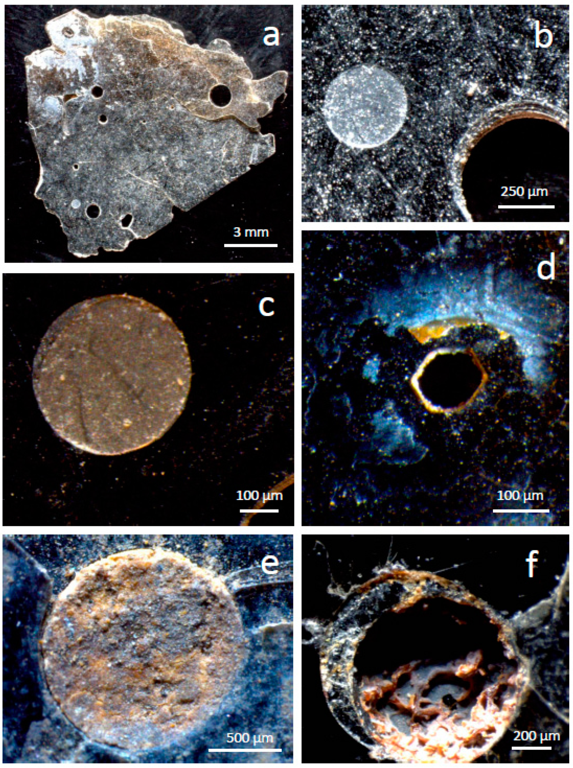
15] reported structures in a phlogopite from Uganda with similarities to the shallow depressions in our study (e.g., Figure 2c), consisting of depressions with internal steps. Shapes varied from near circular to very elongated and their size was smaller (a few nm to several μm) than the shallow depressions in the present study (hundreds of μm). The edges and steps of the depressions were entirely flat, with no sediment on them. From the evidence of bubbles of similar size and shapes containing hydrocarbons, Moro et al. [15] concluded that the depressions were the interior of gas inclusions (bubbles) that had been exposed by crystal exfoliation.
Ghabru et al. [16] described deep holes in altered biotite that they interpreted as due to mineral inclusions where the inclusions had disappeared. In their case, alteration took place within soils (A to C horizons of Gray Luvisols) formed on glacial tills in Saskatchewan. The alteration produced vermiculite and interstratified biotite-vermiculite, where the only chemical change was K loss. Thus, alteration conditions were much milder than in Caldara di Manziana. Although the holes were not considered the product of alteration, Ghabru et al. [16] observed enhanced alteration at the edges of these holes and surrounding areas. One of such structures displayed in Ghabru et al. [16] has a polygonal contour, is ~80 μm wide and is much deeper than is wide. There are signs of alteration within the hole and some debris of unknown composition.
Kurganskaya and Luttge [17] showed depressions on muscovite produced during dissolution experiments conducted at pH 9.4 and 155 °C. The depressions have terraces and their shapes are from elongated and ellipsoidal to pseudo-hexagonal. Their size, however, is below <1 μm, much smaller than those in phlogopite from Caldara di Manziana. Kurganskaya and Luttge [17] showed minute and dispersed particles within and around the depressions, but because their study was performed using AFM, it is not possible to know whether these particles were part of a precipitate deposited by dissolution.
None of the three cases is a good match for the structures and environmental conditions of the samples investigated here. The acidic alteration environment and the alteration products found within the structures in phlogopite from Caldara di Manziana are absent in the Ugandan and Canadian cases. The muscovite investigated by Kurganskaya and Luttge [17] was not in an acidic medium, but it is possible that very thin precipitates were present.

4.2. Acidic Chemical Alteration

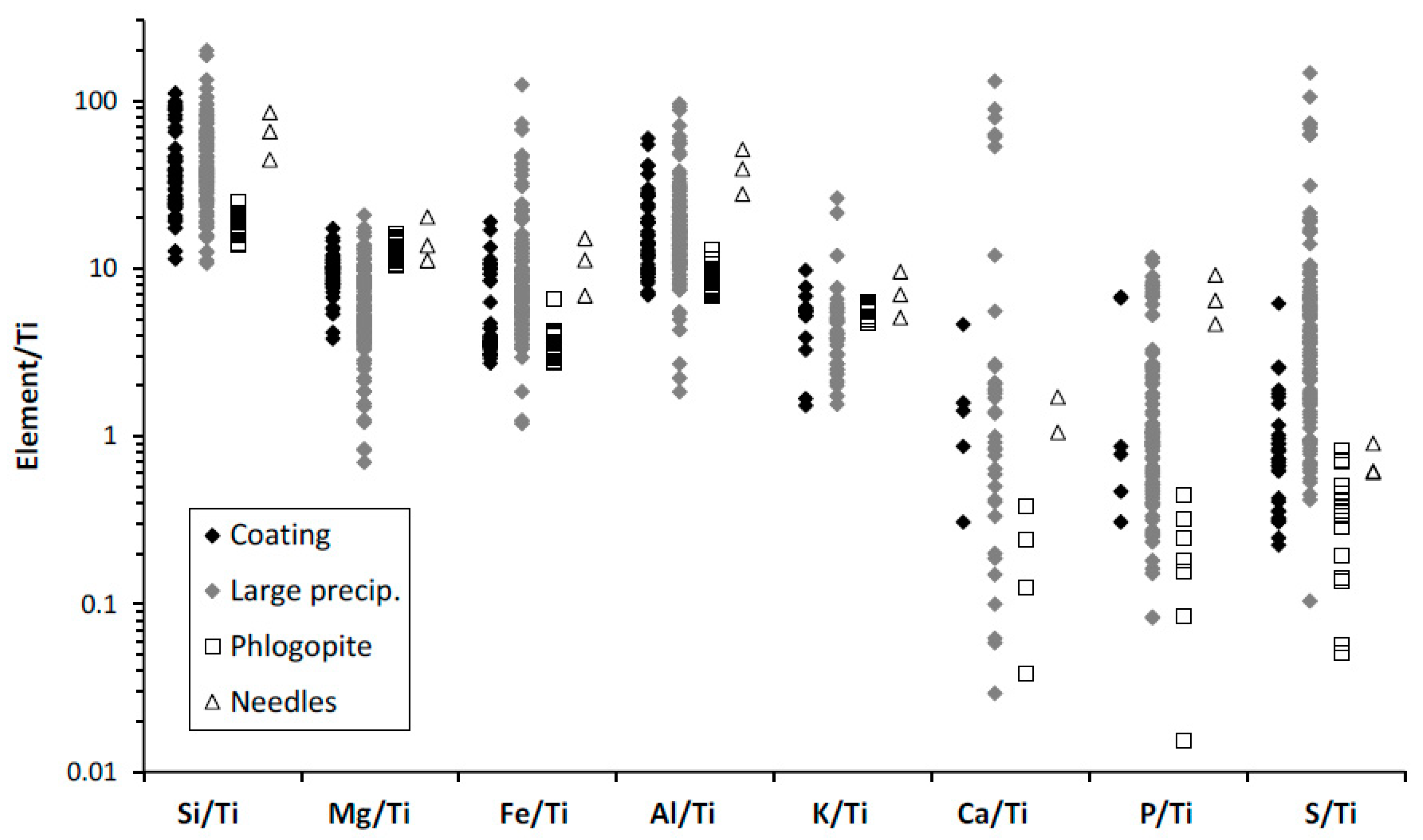
The overall chemical trends are congruent with the alteration of phlogopite taking place by acid attack. There is loss of K and Mg, two highly soluble cations, whereas there is concentration of Si, Al, and Fe (Figure 10 and Figure 11). Iron is less enriched than Si and Al in many cases (Figure 11g,h). These are typical trends of acidic alteration. Kuwahara and Aoki [18] dissolved phlogopite experimentally in 0.01 N HCl. Experiments longer than 6 days, where precipitation products first appeared, reproduced the pattern of cation loss in phlogopite from Caldara di Manziana. Iron- and Mg-rich silicates evolve towards Al silicates when subjected to acid alteration, although not exclusively in such conditions. Kaolinite and halloysite are produced from the alteration of more Mg- and Fe-rich silicates in acidic environments [19,20,
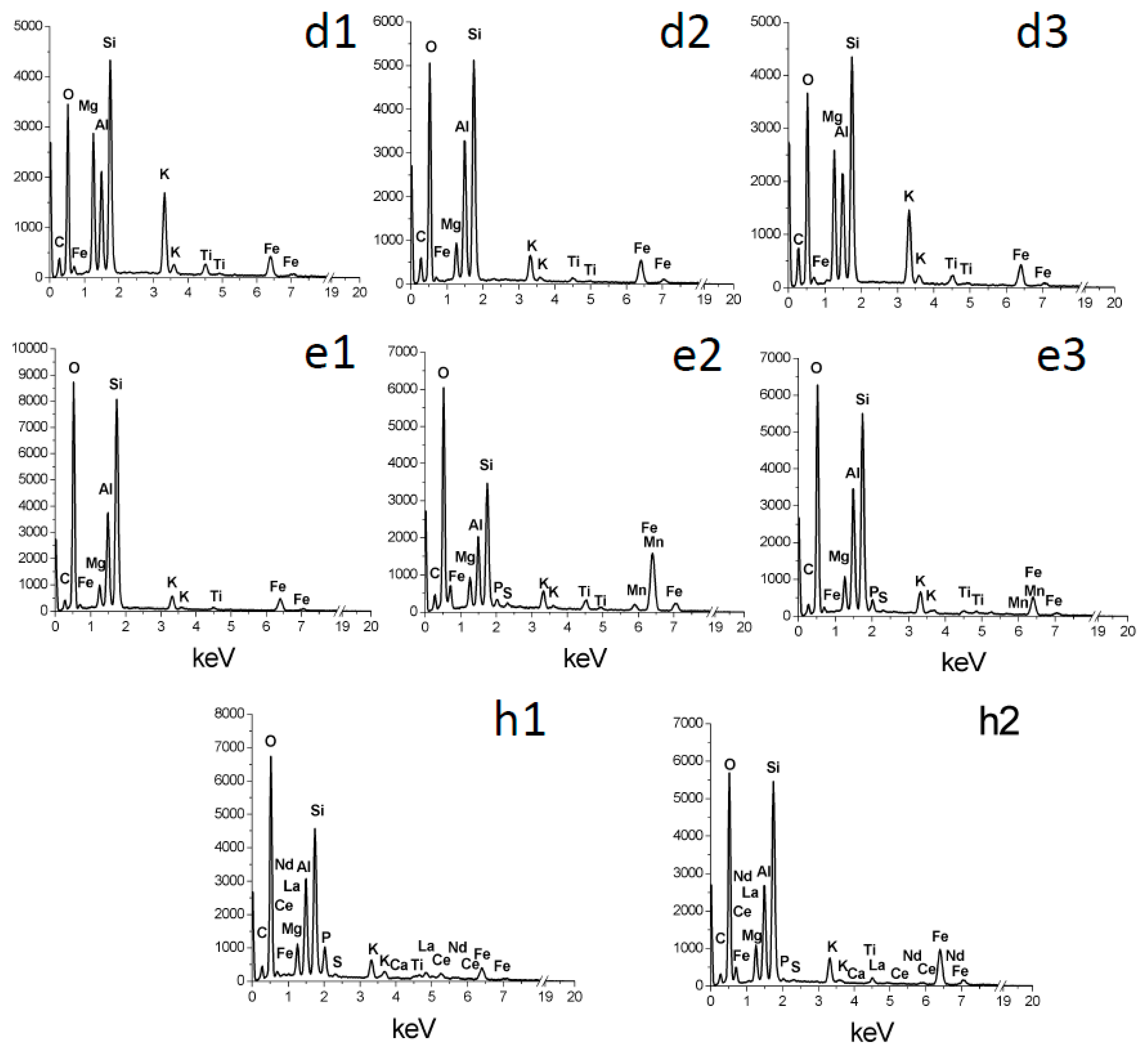
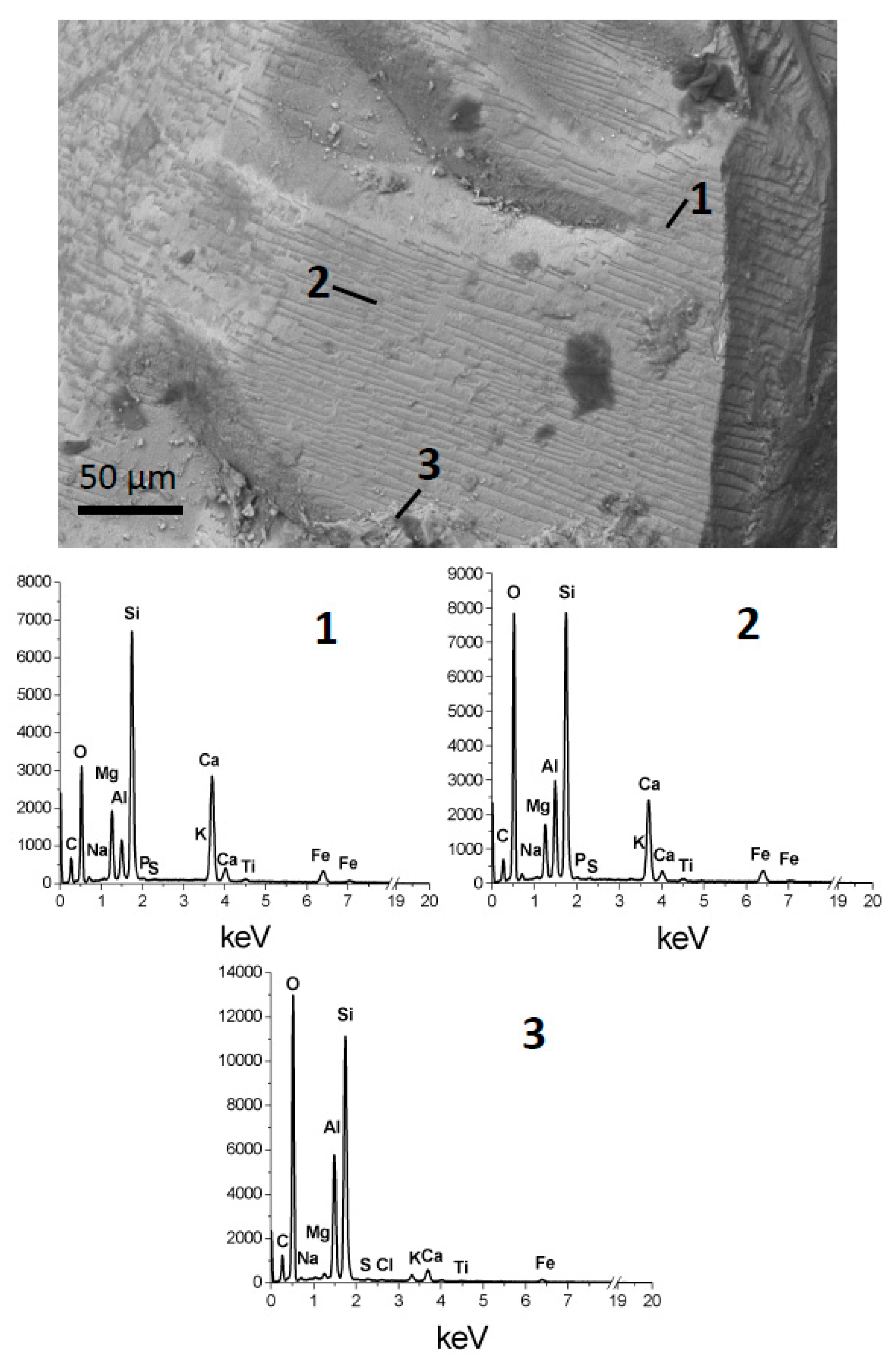
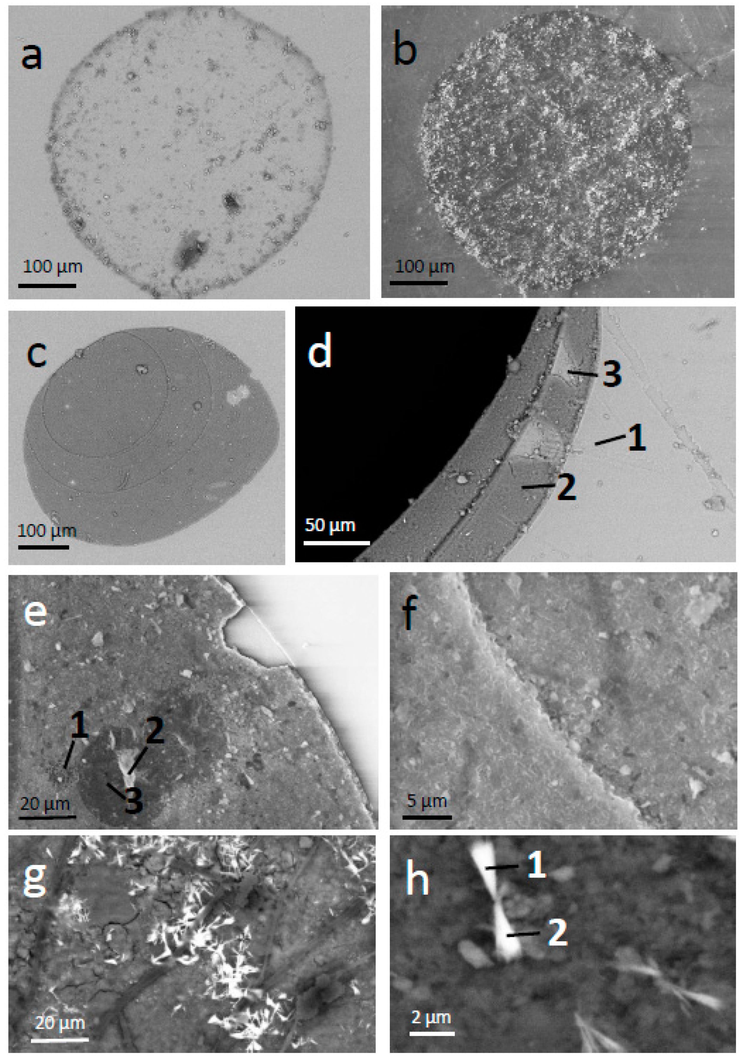
21] while beidellite is possibly a transient product in similar conditions. The thin deposits within depressions and steps in holes have a darker contrast in back-scattered electron images than that of the fresh phlogopite, coherent with a more hydrated composition (Figure 2c,d,e), perhaps containing smectite and/or poorly crystallized, hydrated products. These sediments contain substantial residual Mg (Figure 3d2,e1,e2,e3), indicating incomplete alteration. 
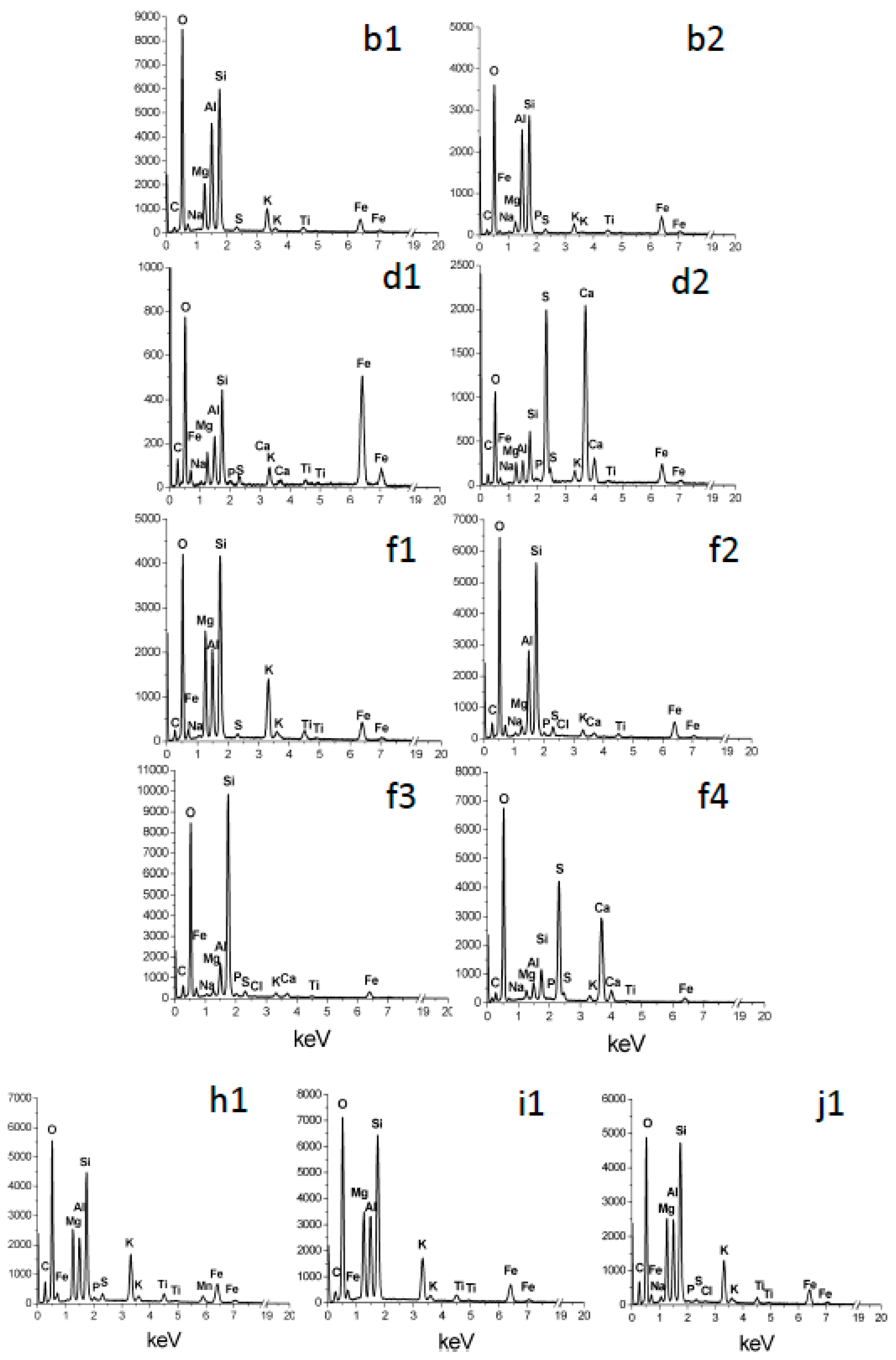
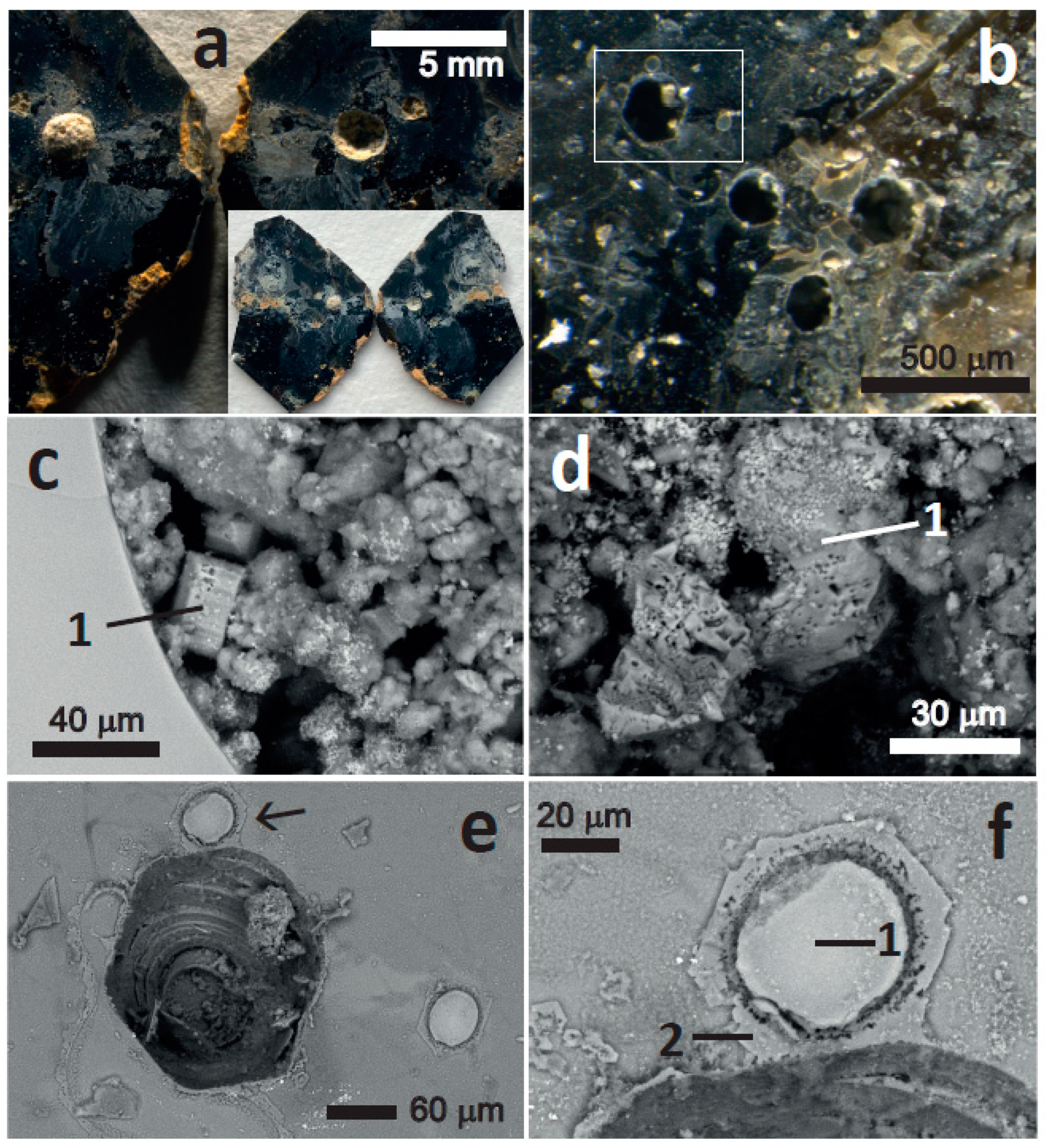
Figure 4b displays two very interesting morphologies, one platy, which can be interpreted as broken-up and partially altered phlogopite plates, still containing much Mg (Figure 5b1), and a mesh of tubular structures with high Al content (Figure 5b2). The latter structure can be interpreted as a silicate containing mainly Si and Al and some K, Fe, and Mg, which could be defined as beidellite. However, the tubular structures are suggestive of halloysite [22], and it can be interpreted that the Mg, K, and Fe are not part of this mineral phase, but contamination of adjacent minerals (e.g., the plates, Fe oxides). It is, however, also possible that Mg, K, and Fe are in halloysite because halloysite and kaolinite are known to incorporate Fe, Mg, and interlayer cations, either within them or as interstratified smectite layers [22,23,24,25]. In any case, the tubes can be safely interpreted as an advanced alteration stage of the original phlogopite.
The coexistence of fresh phlogopite and intensely altered products (Figure 4 and Figure 5) supports an aggressive, intense and localized process, which is more coherent with acid attack than with advanced weathering at near neutral pH. Together with halloysite or beidellite, Fe oxides are also a product of acid attack of Fe-bearing silicates. Particularly, in phlogopite and biotite early disruption of the silicate crystal lattice causes Fe2+ oxidization and release of Fe3+ [26]. Silica is a typical product of intense acid alteration [27]. Gypsum is indicative of sulphate abundance, a natural residuum of sulphuric acid attack [28]. The pseudo-hexagonal films suggestive of jarosite (Figure 6e,f and Figure 7f2) are also compatible with a localized acidic environment.
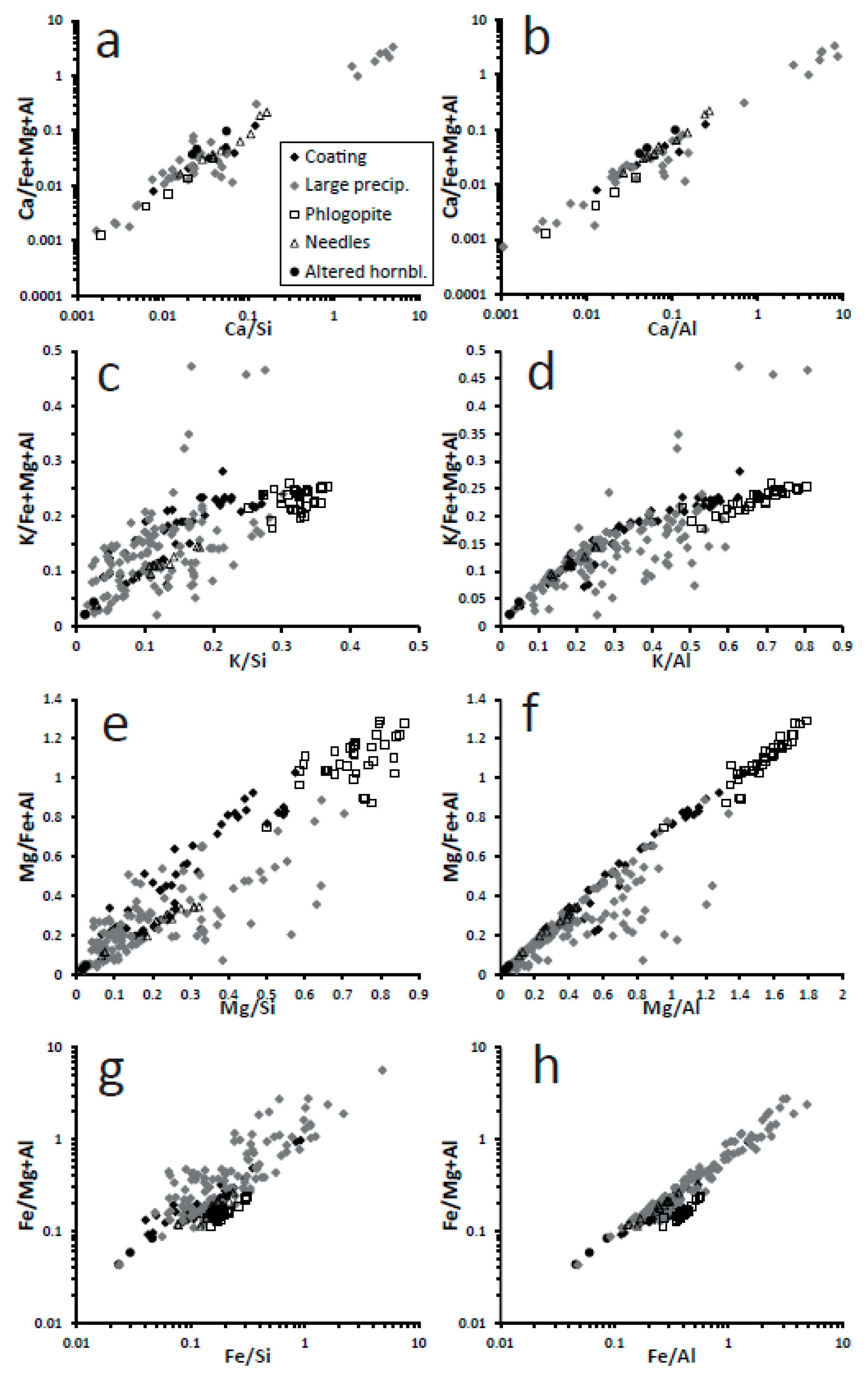
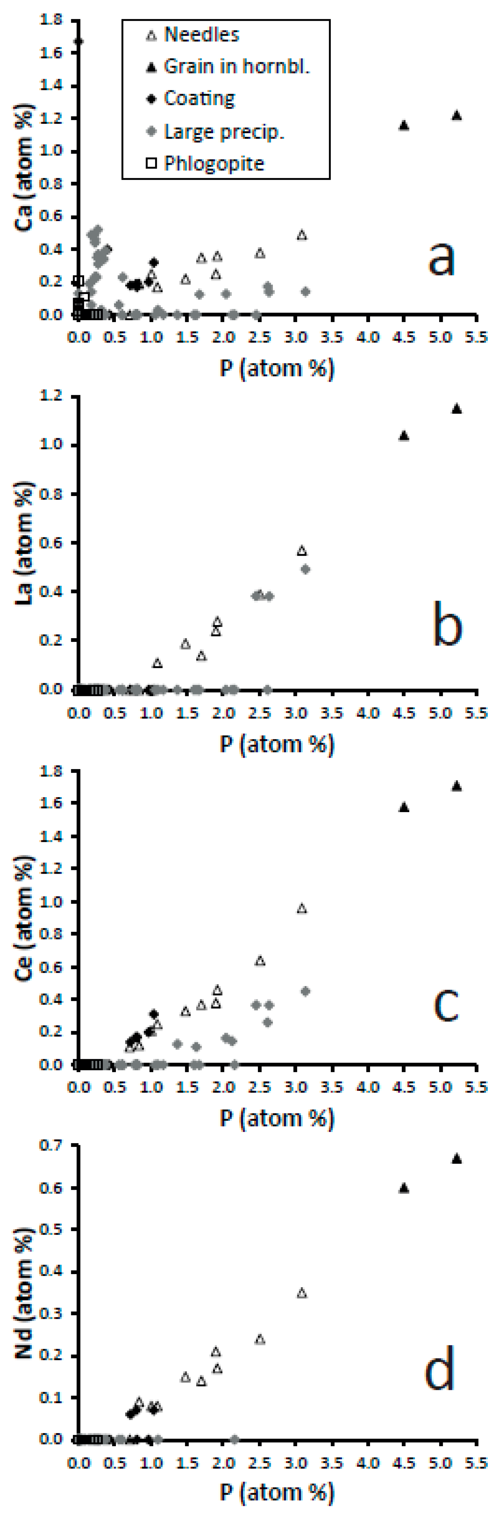
The three data points corresponding to altered hornblende follow almost the same chemical patterns (loss of Mg, Ca, and Fe; concentration of Si and Al) and indicate also acidic alteration (Figure 11). Thus, the global chemical evolution of the alteration products, the composition of each specific alteration product and their morphologies all indicate acidic alteration.

4.3. Generation of Sulphuric Acid

The two major acidic gases emanated at Caldara di Manziana are, in the order of emanation rate, CO2 and H2S [1,6]. Both are mild acids when dissolved in water and unlikely to produce the focused and intense alteration features detected in the present investigation. The existence of elemental sulphur in Caldara di Manziana [7] and the detection of sulphate within alteration cavities in phlogopite (gypsum: Figure 4d,f and Figure 5d2,f4) indicate that sulphur-oxidizing bacteria are causing oxidation of S2− to S0 and SO42−. Sulphur-oxidizing bacteria are at the base of the microbial dissimilatory S cycle. They obtain metabolic energy from oxidizing reduced forms of S in a variety of compounds [29]. Sulphuric acid is then the likely agent that caused the alteration. Shallow depressions with thin coatings were probably produced by diluted or small quantities of acid, whereas deep depressions and holes were produced by larger volumes of concentrated acid. This is consistent with gypsum being observed only in areas of intense alteration and large deposits of sediment, because gypsum would not precipitate from dilute solutions of sulphuric acid (gypsum solubility is ~2 g L−1 at 25 °C [30]).
The phenomenon of bacterial production of H2SO4 from H2S followed by corrosion of steel and concrete elements is well documented in sewages and wastewater treatment facilities, where H2S is the previous result of bacterial activity on the waste (e.g., [31]). The process of biogenic sulphuric acid corrosion is driven by a succession of different bacterial species requiring different environmental pH [32]. Pipes and exposed elements are first colonized by neutrophilic sulphur-oxidizing bacteria, such as Thiobacillus spp. and Thiomonas spp., which generate sulphuric acid and polythionic acids, lowering the pH to 3.5–5.0. As the pH decreases, other bacteria take over, in successive steps, which are capable of living at progressively lower pH, such as Acidithiobacillus thiooxidans, and continue the process of sulphur oxidation and sulphuric acid production from pH 5 to as low as 1–2 [31,33].
It is of particular interest that the genus Acidithiobacillus includes chemolithoautotrophic obligate acidophiles bacteria that can live with elemental sulphur as the only nutrient, producing high amounts of sulphuric acid [34]. After other sulphur-oxidizing bacteria have generated S0, Acidithiobacillus spp. can generate sulphuric acid from this solid S source, meaning that a continuous acid attack of the mineral substrate can take place around the precipitated S0 until it is consumed. An example of species that can accumulate solid S0 that may be especially relevant to this study is that of chemolithotrophic sulphide- and sulphur-oxidizing bacteria (both types oxidize S, although following different biochemical paths). Their optimal habitats are narrow crevices, 0.1–1 mm wide, with low concentrations of dissolved H2S and O2 [35], as it may be the case between the sheets of partially dislodged phlogopite crystals buried in the soil.
All the above-mentioned bacteria live in natural environments with abundant sources of sulphur, including soils [8]. It can be reasonably concluded that the soils of Caldara di Manziana are the source of sulphuric acid by effect of the H2S emanations and sulphur-oxidizing bacteria, and that the sulphuric acid corrodes and alters mineral grains in the soil.

4.4. Model of Phlogopite Acidic Alteration

Water is an essential element of the acidic alteration taking place in Caldara di Manziana because the sulphuric acid is required to be dissolved in water. Caldara di Manziana has a monthly average precipitation ranging from 40 mm, in July, to 171 mm, in November. The minimum and maximum average relative humidity occur in the same months and are 66 and 80%. Annual average precipitation and relative humidity are 99 mm and 74% [36]. Thus, the climate in the area is rather humid. In addition, precipitation in the wettest season causes flooding of the centre of the caldera and water streams appear, while the focused CO2 expulsion from the permanent water pool generates a continuous geyser and spray, all of which contribute to a still higher local relative humidity. As a consequence, minerals in the soil are expected to be frequently wet from rain or atmospheric condensation, and water droplets or films to remain long times on the mineral surfaces before evaporation. These are appropriate conditions for (1) H2S to dissolve in the water and be available to sulphur-oxidizing bacteria and (2) biogenic sulphuric acid to dissolve in the water and attack surfaces in contact with it. Both steps of the process can take place frequently and for extended periods of time in Caldara di Manziana.
The altered material within depressions in the phlogopite crystals may have been produced in situ on the mineral grains or transported from surrounding altered grains in the soil. For example, hornblende phenocrysts in the soil have signs of acidic alteration (Figure 8), indicating that acid attack does not take place exclusively on phlogopite and that translocation of alteration products was possible. Nonetheless, based on the following arguments, the alteration products found on phlogopite are interpreted to correspond to phlogopite alteration. First, shallow depressions had thin precipitates of clay-size flakes (Figure 2) of a silicate composition (Figure 3d2,e1,e2,e3), whereas deep depressions had thick precipitates (Figure 4) covering a wide range of composition and morphology, including Fe oxides and silica (Figure 5b1,b2,d1,d2,f2,f3,f4). Therefore, the intensity of the alteration is correlated with both the amount of material dissolved/altered/precipitated and its alteration stage, which is consistent with the precipitates forming largely in situ. Second, the altered material in phlogopite and hornblende crystals have a distinctive chemical character. Although both fall within the same chemical-ratio trends (
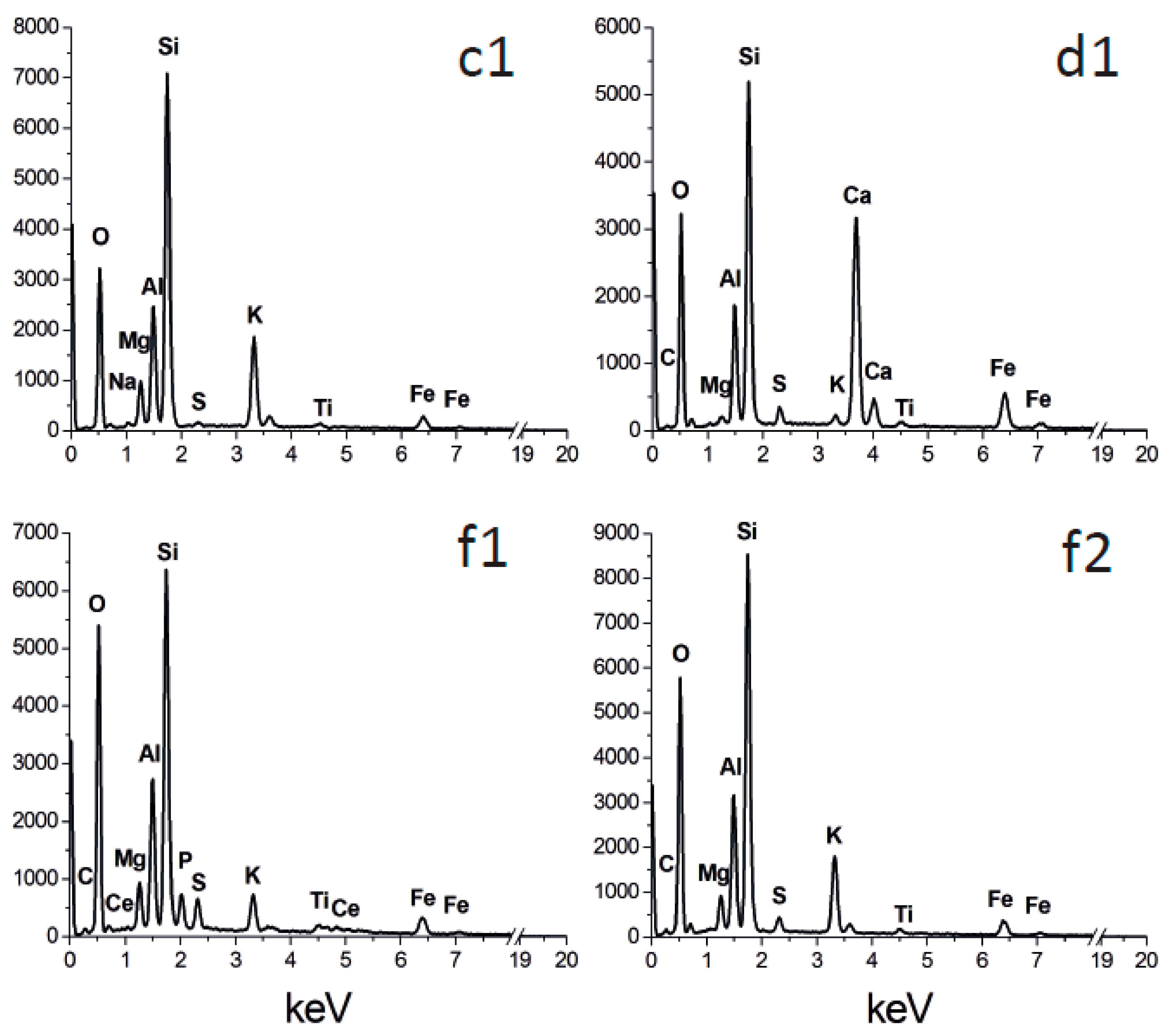
Figure 11), altered hornblende contains Ca (Figure 8), which is not the case of altered phlogopite. This suggests that the altered material found on each mineral originated from the particular mineral. Calcium was found sometimes on altered phlogopite as gypsum (Figure 5d2,f4) and in much smaller concentration as Ca phosphate (Figure 9a). The existence of gypsum is indicative of Ca ions diffusing from the surrounding soil and precipitating with sulphate in areas where strong acid attack was taking place. There is also evidence of the transport and deposition of some foreign particles within deep depressions in phlogopite (K feldspar and hornblende in Figure 6c,d). Thus, some solids and solutes were transported from surrounding soil to the altered phlogopite surfaces, but the evidence indicates them to be a minor component of the sediments on the mica.
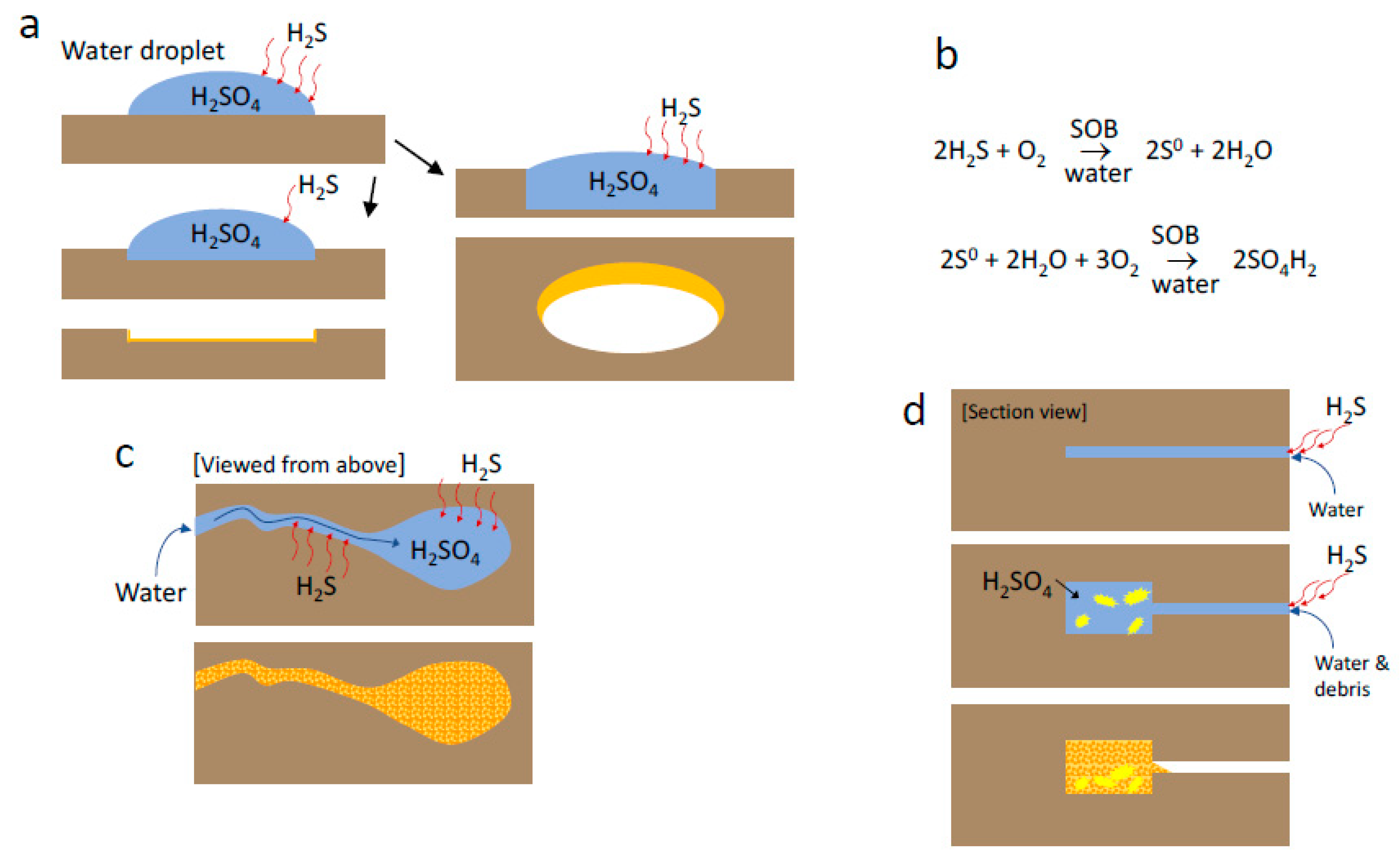
The model of phlogopite alteration is interpreted to be the following. Emanating H2S is dissolved in water on the surface or within partially cleaved crystals of phlogopite, where sulphur-oxidation bacteria oxidize sulphur to H2SO4 (Figure 12) progressively and in stages. At some point, the sulphuric acid is sufficiently concentrated in droplets or water films to corrode the mineral. Shallow depressions (Figure 1b,c and Figure 2a–c,e) and some holes (Figure 2d) produced by either attack on very thin flakes or exfoliation of flakes with shallow depressions are the result of acid attack of droplets with diluted sulphuric acid (left path in Figure 12a). These droplets dissolve small volumes of phlogopite (shallow depressions) and leave a precipitate consisting of a fine-sized silicate and/or amorphous material with low-mobility cations. Proof that the acid concentration is low is that no sulphates or soluble substances precipitate in such depressions. Although phlogopite has low resistance to acid attack [37] effective corrosion by dilute acid solutions requires a sustained period of attack, where water droplets are supposedly maintained by condensation of surrounding moisture. Moreover, consumed acid may need to be replaced, perhaps by diffusion from surrounding areas. Alternatively, micro-grains of S0 precipitated by sulphur-oxidizing bacteria may be further oxidized to H2SO4 in the presence of water by mediation of other sulphur-oxidizing bacteria. The acid would then corrode the phlogopite surface in situ as new acid continues to be generated. This possibility provides the necessary replacement of acid to sustain the attack. The depth of the depression is controlled by the length of the attack, while the length of the attack is controlled by the availability of sulphuric acid. Acid availability can depend on a number of factors: proximity to a source of H2S, concentration of sulphur-oxidation bacteria, concentration of S0 grains, and length of the life of droplets or films where the acid is active. All of these factors are represented generically by H2S availability in Figure 12, where low availability results in a shallow depression (left path of Figure 12a), and high availability (but always resulting in dilute acid concentration), producing deeper depressions and eventually a hole (right path in Figure 12a).
High concentration of sulphuric acid in water droplets and films generates deep depressions and holes, where there are abundant precipitates with a wide range of compositions (partially altered phlogopite, beidellite or Fe,K-halloysite, silica, Fe oxides, and gypsum; Figure 12c,d). Some debris from the surrounding soil may also be deposited in depressions and the phlogopite surface (Figure 12d). The shapes of these cavities are variable and indicate different amount of acidic water as well as different interaction acid-phlogopite surface due to variables such as fluid-solid contact angle, phlogopite topography or angle of inclination of the mineral flakes. Some of such depressions are created by drops (Figure 1, Figure 2a–e, Figure 4c,e and Figure 6a–c,e,f), some by drops with a trail (Figure 4j), some by advancing water corroding walls in different fashions perhaps following areas of weaker structure (Figure 4a,g). High acid concentration and large volume of acid (i.e., large droplets and extended films) both promote longer attack. Conversely, these three factors, i.e., more aggressive acid, larger amount of acidic fluid, and longer life of the attack, cause greater irregularity of the corroded areas.
It is interesting that the shape of depressions or holes produced by droplets ranges from rounded to pseudo-hexagonal (Figure 1 and Figure 6). It is interpreted that rounded structures reflect the shape of the droplet on the phlogopite surface and indicate that the acidic attack took place similarly in every direction. Pseudo-hexagonal structures were created where the line of attack was controlled by the crystal symmetry of the mica. The condition for such a control is that the acid is not overly aggressive. In the same way as slow crystallization of phyllosilicates produces pseudo-hexagonal plates, slow dissolution produces pseudo-hexagonal cavities. Kurganskaya and Luttge [17] show hexagonal to pseudo-hexagonal dissolution pits on the basal planes of muscovite. Slow growth and slow dissolution of minerals are controlled by the same principle: the crystallographic faces manifested are those containing the strongest bonds, according to the theory of periodic bond chains [17]. The conditions within a depression may have changed over time, because the acid became more concentrated with time, as it dissolved the crystal deeper down, or because the dissolution of the phlogopite surface was a different event from the dissolution deep below the surface (e.g., a different cycle of water deposition and production or accumulation of sulphuric acid). This may be the reason why some depressions modified their shape with depth from pseudo-hexagonal to rounded (Figure 6e).
The formation of approximately concentric terraces is a common dissolution phenomenon of phyllosilicates that form large crystals because they have a marked crystal anisotropy between the c* axis and the plane containing the a and b axes (they are structures of piled sheets) and the dissolution is faster within the ab plane than in the c* direction [17,18,38,39]. Dissolution starts at weak points, such as dislocations, on the phlogopite surface. As dissolution proceeds faster laterally (ab plane) than vertically (c* direction) the formation of terraces is a natural phenomenon. The actual size and shape of the terraces is dependent on the intensity of the attack (in the present case, acid concentration), concentration of crystal defects, composition of the phyllosilicate, and protecting coating formed by precipitation, all of which modify the relative velocity of mica dissolution in one and the other direction. Generally, it would be expected that dilute acid generates wide terraces because the dissolution rate in the ab plane is faster than in the c* direction and the acid within the water droplet is consumed relatively quickly, so that the initial dissolution structure is preserved. Concentrated acid, however, will probably generate a chaotic morphology where terraces are absent in some places or have very different shapes, as controlled by changing conditions due to the fast dissolution and precipitation reactions [39] and to modification of sulphuric acid concentration. This is coherent with the well-defined and relatively wide terraces observed in depressions and holes generated with diluted acid (Figure 2) and with the more chaotic structures found where concentrated acid corroded phlogopite (Figure 4 and Figure 6).
It is possible that the type of alteration represented in Figure 12d is the most common in phlogopite, i.e., that the conditions for the formation of depressions are most frequently met on the surfaces of partly cleaved crystals, but that the large majority of such crystals break up completely into two or more exfoliated flakes with depressions and holes of different character. Water within these partly cleaved crystals would evaporate slowly and allow for a sustained presence of sulphuric acid. There is, however, evidence that acidic alteration takes place on external mineral surfaces, as shown by altered hornblende, where attack on the outer surface is the only possibility. In these cases, contact with other mineral grains from the soil (in the surface of the soil or below it) may be also a mechanism to generate stable water droplets where acidic alteration may be sustained.

4.5. Unusual Dissolution and Precipitation Features

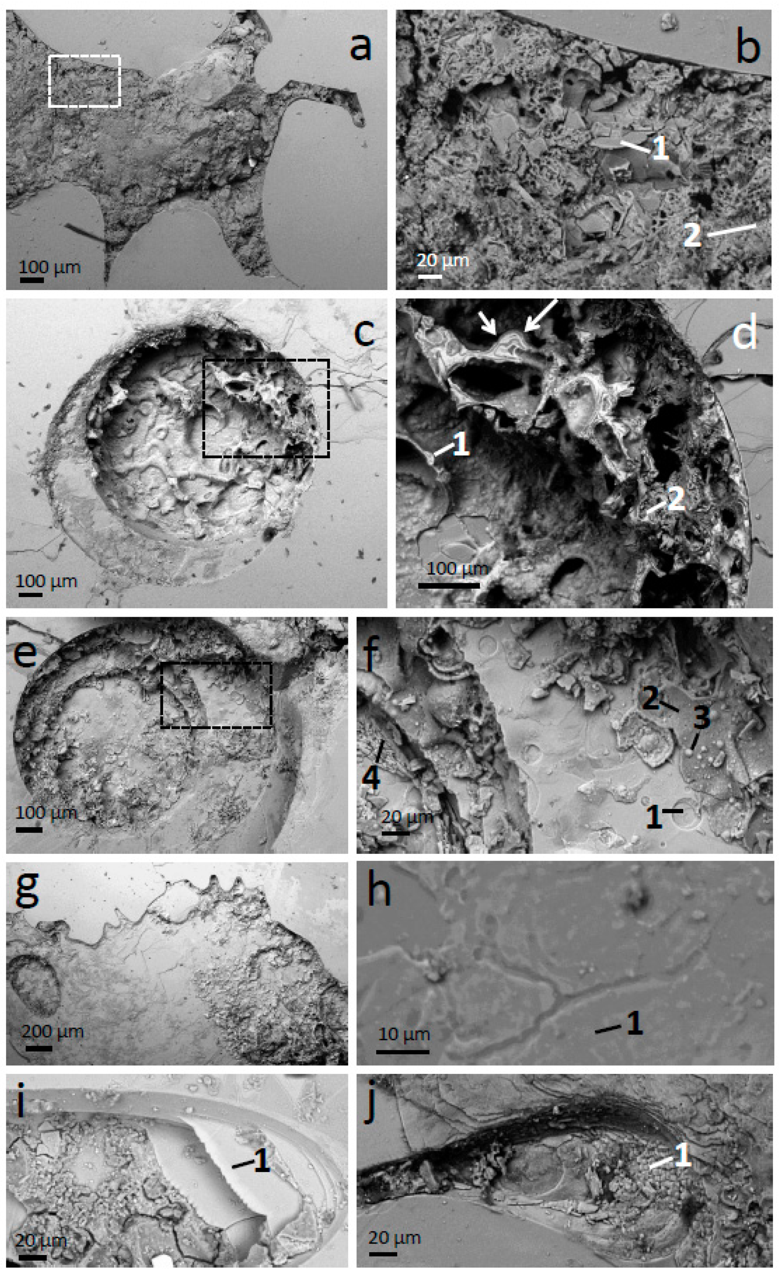
The SEM images of altered phlogopite display a group of unusual features. Figure 4i shows a strongly altered area which is partly a depression and partly a hole. The depression is filled with a thick layer of alteration products with micro-cracks. Interestingly, some layers of phlogopite did not dissolve completely even if other layers between them did. The result is the building up of terraces of fairly pristine phlogopite (Figure 5i1) separated by alteration products or with nothing in between them. It is surprising that the acid attacked and consumed phlogopite layers above and below and did not attack these portions that form the terraces. A related structure is present in Figure 4j, where scales of fairly pristine phlogopite exist (Figure 5j1). The scale structures appear to be at several heights (going higher up from left to right) and connected, creating a system of terraces with the appearance of scales. The scale appearance is generated by the fact that the terraces terminate in angles suggestive of a pseudo-hexagonal shape (two to four angles of ~120° are observed in many of the scales; there are several scales in each terrace). This structure must have been created by the partial dissolution of phlogopite layers, where the edges dissolved following the 120° angles of the planar symmetry of phlogopite (angles between two 110 crystallographic faces and between 110 and 010 faces). The scales are then another example of acid dissolution controlled by the phlogopite internal symmetry. The terrace and scale-like structures are indicative of very inhomogeneous acid alteration within the affected areas, because in the same depression there is, on the one hand, complete dissolution of phlogopite and large precipitates and, on the other, remains of phlogopite layers of almost pristine composition and showing slow dissolution controlled by crystal symmetry.
Perhaps a related path of strong (but always localized) alteration of phlogopite may be that represented in Figure 4a,b, where phlogopite plates in advanced state of alteration (Figure 5b1) coexist with tubes of halloysite or beidellite (Figure 5b2). The plates appear to be broken up into pieces, as if one or several large plate-like structures had collapsed. There seems to be physical continuity between some plates and tubes, as if further alteration of the plates generates the tubes. This suggests the existence of large platy structures within the depression that have been subsequently altered into the mass of plates and tubes observed in Figure 4a,b. It is interesting also that the top, right branch of the depression in Figure 4a has an upper outline of three straight lines with angles of ~120°, and a more rounded outline at the bottom. This channel structure manifests heterogeneous dissolution conditions at distances < 100 μm, across the corresponding channel and between the channel and the rest of the depression.
Another unusual feature, now corresponding to a precipitation process, is the generation of hexagonal films around deep depressions. Such large structures (~50 μm across) are in Figure 6e,f, but much smaller pseudo-hexagonal films are also observed in the left, bottom area of Figure 6f. These films are interpreted to consist of jarosite, based on the combined presence of S, K and Fe (Figure 7f2) and the pseudo-hexagonal shape of the films. These films seem to have developed from the depression and grown radially outwards. They may have precipitated as sulphate, Fe3+, and K ions diffused out of the depression during the acid dissolution. The crystal where these structures were found was partially cleaved, but both sides across the cleavage surface remained in contact. This may explain the existence of a water film between both sides where the ions could diffuse radially and precipitate generating a mineral film. If the mineral film consists of jarosite, then the water film around the depression must have had a pH < 3, at which jarosite is stable [40]. Moreover, the diffusion and precipitation must have taken place slowly to allow the growth of a single, extended film with a crystallographically controlled shape. The existence of a low-pH water film within the cleavage is consistent with the signs of chemical alteration of the phlogopite under the jarosite film (Figure 7f2). However, the proximity of the EDX analysis point to the material within the depression may have contaminated it (Figure 6f).

Supplementary Materials

The following are available online at https://0-www-mdpi-com.brum.beds.ac.uk/article/10.3390/min11050547/s1, Figure S1 and collection of SEM–EDS results that appear in EDX spectra and chemical results in the article.

Author Contributions

Conceptualization, F.P. and J.C.; methodology, F.P. and J.C.; validation, F.P.; formal analysis, F.P. and J.C.; investigation, F.P.; resources, F.P.; data curation, F.P. and J.C.; writing—original draft preparation, J.C.; writing—review and editing, F.P. and J.C.; visualization, J.C.; project administration, F.P. and J.C. All authors have read and agreed to the published version of the manuscript.

Funding

This research received no external funding.

Institutional Review Board Statement

Not applicable.

Informed Consent Statement

Not applicable.

Data Availability Statement

All data supporting the interpretations in this article are contained in the article and its Supplementary Material.

Acknowledgments

We thank Emma Humphreys-Williams for the discussions and help with the acid attack experiments on phlogopite, Benita Schmidt for help with the same acid attack experiments, Martin Zilli for invaluable support with sample collection, and the administrative staff of the Regional Natural Site in the persons of Daniele Badaloni (Director) and Guido Baldi (Ranger). The four anonymous reviewers are thanked for their comments, which improved the manuscript.

Conflicts of Interest

The authors declare no conflict of interest.

References

  1. Costa, A.; Chiodini, G.; Granieri, D.; Folch, A.; Caliro, S.; Avino, R.; Cardellini, C. A shallow-layer model for heavy gas dispersion from natural sources: Application and hazard assessment at Caldara di Manziana, Italy. Geochem. Geophys. 2008, 9, Q03002. [Google Scholar] [CrossRef]
  2. Peccerillo, A. Cenozoic Volcanism in the Tyrrhenian Sea Region, 2nd ed.; Springer: Cham, Switzerland, 2017; p. 398. [Google Scholar]
  3. Alagna, K.E.; Peccerillo, A.; Martin, S.; Donati, C. Tertiary to present evolution of Orogenic magmatism in Italy. J. Virtual Explor. 2010, 36, 18. [Google Scholar] [CrossRef]
  4. Rogie, J.D.; Kerrick, D.M.; Chiodini, G.; Frondini, F. Flux measurements of nonvolcanic CO2 emissions from some vents in central Italy. J. Geophys. Res. 2000, 105, 8435–8445. [Google Scholar] [CrossRef]
  5. Chiodini, G.; Frondini, F.; Kerrick, D.M.; Rogie, J.D.; Parello, F.; Peruzzi, L.; Zanzari, A.R. Quantification of deep CO2 fluxes from central Italy: Examples of carbon balance for regional aquifers and of soil diffuse degassing. Chem. Geol. 1999, 159, 205–222. [Google Scholar] [CrossRef]
  6. Ranaldi, M. Studio Delle Emissioni di Gas in Aree Vulcaniche e Geotermiche: Implicazioni Struturali, Geotermiche e di Pericolosità. Ph.D. Thesis, Università degli Studi Roma Tre, Rome, Italy, 2008. [Google Scholar]
  7. Lombardi, G.; Mattias, P. Petrology and mineralogy of the kaolin and alunite mineralizations of Latium (Italy). Geol. Romana 1979, 18, 157–214. [Google Scholar]
  8. Richards, B.N. The Microbiology of Terrestrial Ecosystems; Longman Scientific and Technical: Harlow, UK, 1987. [Google Scholar]
  9. Pinzari, F.; Cuadros, J.; Napoli, R.; Canfora, L.; Baussà Bardají, D. Routes of phlogopite weathering by three fungal strains. Fungal Biol. 2016, 120, 1582–1599. [Google Scholar] [CrossRef] [Green Version]
  10. Goldstein, J.; Newbury, D.; Joy, D.; Lyman, C.; Echlin, P.; Lifshin, E.; Sawyer, L.; Michael, J. Scanning Electron Microscopy and X-ray Microanalysis, 3rd ed.; Springer Science, Business Media Inc.: New York, NY, USA, 2003. [Google Scholar]
  11. Pan, Y.; Fleet, M.E. Compositions of the apatite-group minerals: Substitution mechanisms and controlling factors. In Phosphates-Geochemical, Geobiological, and Materials Importance; Reviews in Mineralogy and Geochemistry; Kohn, M.J., Rakovan, J., Hughes, J.M., Eds.; Mineralogical Society of America: Washington, DC, USA, 2002; Volume 48, pp. 13–50. [Google Scholar]
  12. Boatner, L.A. Synthesis, structure and properties of monazite, pretulite and xenotime. In Phosphates-Geochemical, Geobiological, and Materials Importance; Reviews in Mineralogy and Geochemistry; Kohn, M.J., Rakovan, J., Hughes, J.M., Eds.; Mineralogical Society of America: Washington, DC, USA, 2002; Volume 48, pp. 87–122. [Google Scholar]
  13. Long, D.T.; Fegan, N.E.; McKee, J.D.; Lyons, W.B.; Hines, M.E.; Macumber, P.G. Formation of alunite, jarosite and hydrous iron oxides in a hypersaline system: Lake Tyrrell, Victoria, Australia. Chem. Geol. 1992, 96, 183–202. [Google Scholar] [CrossRef]
  14. Mindat.org. Jarosite from Monterniers Mines, Lantignié, Villefranche-sur-Saône, Rhône, Auvergne-Rhône-Alpes, France. Available online: https://www.mindat.org/photo-674216.html (accessed on 23 March 2021).
  15. Moro, D.; Valdrè, G.; Mesto, E.; Scordari, F.; Lacalamita, M.; Della Ventura, G.; Bellatreccia, F.; Scirè, S.; Schingaro, E. Hydrocarbons in phlogopite from Kasenyi kamafugitic rocks (SW Uganda): Cross-correlated AFM, confocal microscopy and Raman imaging. Sci. Rep. 2017, 7, 40663. [Google Scholar] [CrossRef] [PubMed] [Green Version]
  16. Ghabru, S.K.; Mermut, A.R.; St. Arnaud, S.J. The nature of weathered biotite in sand-sized fractions of Gray Luvisols (Boralfs) in Saskatchewan, Canada. Geoderma 1987, 40, 65–82. [Google Scholar] [CrossRef]
  17. Kurganskaya, I.; Luttge, A. A comprehensive stochastic model of phyllosilicate dissolution: Structure and kinematics of etch pits formed on muscovite basal face. Geochim. Cosmochim. Acta 2013, 120, 545–560. [Google Scholar] [CrossRef]
  18. Kuwahara, Y.; Aoki, Y. Dissolution process of phlogopite in acid solutions. Clays Clay Miner. 1995, 43, 39–50. [Google Scholar] [CrossRef]
  19. Schultz, L.G.; Shepard, A.O.; Blackmon, P.D.; Starkey, H.C. Mixed-layer kaolinite-montmorillonite from the Yucatan Peninsula. Mexico. Clays Clay Miner. 1971, 19, 137–150. [Google Scholar] [CrossRef]
  20. Straub, J.R.; Cohen, A.D. Kaolinite-enrichment beneath coals; a modern analog, Snuggedy Swamp, South Carolina. J. Sedim. Petrol. 1978, 48, 203–210. [Google Scholar]
  21. Watanabe, T.; Sawada, Y.; Russell, J.D.; McHardy, W.J.; Wilson, M.J. The conversion of montmorillonite to interstratified halloysite-smectite by weathering in the Omni acid clay deposit, Japan. Clay Miner. 1992, 27, 159–173. [Google Scholar] [CrossRef]
  22. Papoulis, D.; Tsolis-Katagas, P.; Katagas, C. Progressive stages in the formation of kaolin minerals of different morphologies in the weathering of plagioclase. Clays Clay Miner. 2004, 52, 275–286. [Google Scholar] [CrossRef]
  23. Dudek, T.; Cuadros, J.; Fiore, S. Interstratified kaolinite-smectite: Nature of the layers and mechanism of smectite kaolinization. Am. Miner. 2006, 91, 159–170. [Google Scholar] [CrossRef]
  24. Ryan, P.C.; Huertas, F.J. The temporal evolution of pedogenic Fe–smectite to Fe–kaolin via interstratified kaolin–smectite in a moist tropical soil chronosequence. Geoderma 2009, 151, 1–15. [Google Scholar] [CrossRef]
  25. Van Ranst, E.; Kips, P.; Mbogoni, J.; Mees, F.; Dumon, M.; Delvaux, B. Halloysite-smectite mixed-layered clay in fluvio-volcanic soils at the southern foot of Mount Kilimanjaro, Tanzania. Geoderma 2020, 375, 114527. [Google Scholar] [CrossRef]
  26. Wilson, M.J. Weathering of the primary rock-forming minerals: Processes, products and rates. Clay Miner. 2004, 39, 233–266. [Google Scholar] [CrossRef] [Green Version]
  27. Rodgers, K.; Cook, K.L.; Browne, P.; Campbell, K. The mineralogy, texture and significance of silica derived from alteration by steam condensate in three New Zealand geothermal fields. Clay Miner. 2002, 37, 299–322. [Google Scholar] [CrossRef]
  28. Zimbelman, D.R.; Rye, R.O.; Breit, G.N. Origin of secondary sulfate minerals on active andesitic stratovolcanoes. Chem. Geol. 2005, 215, 37–60. [Google Scholar] [CrossRef] [Green Version]
  29. Fike, D.A.; Bradley, A.S.; Leavitt, W.D. Geomicrobiology of sulfur. In Erlich’s Geomicrobiology, 6th ed.; Erlich, H.L., Newman, D.K., Kappler, A., Eds.; CRC Press: Boca Raton, FL, USA, 2016; pp. 479–515. [Google Scholar]
  30. Bock, E. On the solubility of anhydrous calcium sulphate and of gypsum in concentrated solutions of sodium chloride at 25 °C, 30 °C, 40 °C, and 50 °C. Can. J. Chem. 1961, 39, 1746–1751. [Google Scholar] [CrossRef]
  31. Stanaszek-Tomala, E.; Fiertak, M. Biological corrosion in the sewage system and the sewage treatment plant. Procedia Eng. 2016, 161, 116–120. [Google Scholar] [CrossRef] [Green Version]
  32. Okabe, S.; Odagiri, M.; Ito, T.; Satoh, H. Succession of sulfur-oxidizing bacteria in the microbial community on corroding concrete in sewer systems. Appl. Environ. Microbiol. 2007, 73, 971–980. [Google Scholar] [CrossRef] [PubMed] [Green Version]
  33. Huber, B.; Herzog, B.; Drewes, J.E.; Koch, K.; Müller, E. Characterization of sulfur oxidizing bacteria related to biogenic sulfuric acid corrosion in sludge digesters. BMC Microbiol. 2016, 16, 153. [Google Scholar] [CrossRef] [Green Version]
  34. Robertson, L.A.; Kuenen, J.G. The genus Thiobacillus. Prokaryotes 2006, 5, 812–827. [Google Scholar] [CrossRef]
  35. Fenchel, T.; King, G.M.; Blackburn, T.H. Aquatic Sediments. In Bacterial Biogeochemistry, 3rd ed.; Fenchel, T., King, G.M., Blackburn, T.H., Eds.; Academic Press: Cambridge, MA, USA, 2012; pp. 121–142. [Google Scholar] [CrossRef]
  36. Climatedata.org. Available online: https://en.climate-data.org/europe/italy/lazio/manziana-655548/#climate-graph (accessed on 3 March 2021).
  37. Kalinowski, B.E.; Schweda, P. Kinetics of muscovite phlogopite and biotite dissolution and alteration at pH 1–4, room temperature. Geochim. Cosmochim. Acta 1996, 60, 367–385. [Google Scholar] [CrossRef]
  38. Rufe, E.; Hochella, M. Quantitative assessment of reactive surface area of phlogopite during acid dissolution. Science 1999, 285, 874–876. [Google Scholar] [CrossRef]
  39. Pachana, K.; Zuddas, P.; Censi, P. Influence of pH and temperature on the early stage of mica alteration. Appl. Geochem. 2012, 27, 1738–1744. [Google Scholar] [CrossRef]
  40. Das, G.K.; Acharya, S.; Anand, S.; Das, R.P. Jarosites: A review. Miner. Process. Extr. Metall. Rev. 1996, 17, 185–210. [Google Scholar] [CrossRef]
Figure 1. Stereomicroscopy pictures of a phlogopite flake with multiple holes. (a) General view. (b) Detail of two holes. One penetrates across the flake (right) and shows steps as if the hole had a slightly different diameter or shape across the flake thickness. The other hole (left) does not penetrate the entire flake (these structures are referred to as depressions). (c) Detail of the depression in (b). The interior of the depression has a precipitate that is not present outside. On the upper-left part of the depression there is a step half way between the surface of the flake and the bottom of the depression. (d) Hole with a sub-hexagonal symmetry. (e) Depression that has been filled with a precipitate; there is a similar precipitate outside the depression. (f) Depression with a step and a large precipitate of orange colour; a similar material was visible outside the depression.
Minerals 11 00547 g001
Figure 2. SEM micrographs of different features of the holes in phlogopite. The numbers and lines indicate the location of EDX analyses in Figure 3. (a) Back-scattered electrons (BSE) image of a depression. The bottom of the depression is coated with particles that do not exist in areas outside it. (b) The same area in (a) observed with secondary electrons (SE), showing a great concentration of particles within the depression. (c) BSE image of a depression, with descending steps of ellipsoidal shape. The coating on the depression is apparent by the darker contrast compared to the surface outside it. (d) BSE image of a hole, with two steps. The dark contrast in the steps is produced by the coating. The coating is missing in two spots of the higher step within the hole, where the surface of the phlogopite appears with the same contrast as outside the hole. To the right of the steps there is a straight, shallow trough that suggests erosion by fungal hyphae. (e) SE detailed image of the edge of a depression, with a thin coating of particles. Part of the coating is missing, where the clean phlogopite surface is visible. At the very edge of the depression the coating displays a different structure, apparently corresponding to orientation parallel to the vertical part of the step. (f) SE image of the detail of the coating at one of the steps, showing that the coating consists of multiple flaky particles ≤2 µm in diameter. (g) BSE image of the coating within a depression showing elongate particles of light contrast rich in P. Long branching structures that look like fungal hyphae are also observable. (h) Detail (BSE) of the elongated, P-rich particles, showing that they consist of groups of needles. The very small flake-like particles making up the coating on the depression are also observable.
Minerals 11 00547 g002
Figure 3. EDX spectra of the areas indicated in Figure 2. Spectra (d1d3) are from Figure 2d: (d1) phlogopite outside the hole; (d2) coating on the steps within the hole and (d3) phlogopite in the step of the hole, where the coating is missing. Spectra (e1e3) are from Figure 2e, all of them corresponding to the coating within a depression. Spectra (h1,h2) are from Figure 2h, corresponding to two stacks of needles with light contrast.
Minerals 11 00547 g003
Figure 4. SEM BSE images of the phlogopite surface with depressions of different types containing large amounts of precipitates. The numbers and lines indicate the location of EDX analyses in Figure 5. (a) Irregular depression completely filled with precipitates. The particle with white contrast at the right of the depression is barite. (b) Detail of (a) showing fractured plate structures and a mesh of tubular structures. (c) Circular depression with one step, containing abundant sediment (the same depression in Figure 1f). There is some sediment outside the depression. (d) Detail of (c) showing the intricate structure of the sediment, with bubble-like shapes, and layers of different contrast forming the walls of the bubbles (arrows). The sediment has been lost in one area at the bottom and the phlogopite is exposed. (e) Complex circular depression with multiple steps. Many areas at the edge of the of the depression show signs of corrosion and there are precipitates within and outside the depression. (f) Detail of (e) showing flakes of sediments on depression steps, smaller depressions on the phlogopite surface, numerous gypsum crystals (spectrum f4 in Figure 5), and small spheres rich in Si (spectrum f3 in Figure 5). (g) Large depression on the phlogopite surface with an irregular border, containing abundant precipitates and an elongate depression (left). (h) Detail of the apparently pristine phlogopite surface, with marks indicating coating or dissolution features. (i) Depression (partly bottomless) filled with abundant precipitates. Three sheets of phlogopite (spectrum i1 in Figure 5) protrude stepwise into the interior of the depression. This depression is connected to a channel (not shown), as in (j), located opposite the three sheet steps, on the left. (j) Depression consisting of a channel terminating in an ellipsoidal perforation. There are signs of corrosion around the depression. There are scale-like structures forming terraces with certain similarity to those in (i) and, also like them, consisting of unaltered phlogopite.
Minerals 11 00547 g004
Figure 5. EDX spectra of analysed spots in Figure 4. Spectra of a plate (b1) and tubular mesh (b2) in Figure 4b. Spectra of sediment with a foam-like structure (d1) and of small gypsum crystals (d2) from Figure 4d. Spectra from Figure 4f: (f1) bottom of a small depression indicating a phlogopite composition; (f2) sediment of alteration products; (f3) small Si-rich sphere; (f4) gypsum crystals. (h1) Spectrum of phlogopite surface in Figure 4h. This surface was part of a large flat area on a crystal with depressions containing large precipitates. Spectra (i1) and (j1) are from terrace structures of phlogopite in depressions, from Figure 4i,j.
Minerals 11 00547 g005
Figure 6. Stereomicroscopy and SEM BSE images of a particle that was partially cleaved. Numbers and lines in the SEM images indicate the location of EDX analyses. While handling this particle, it cleaved completely and revealed alteration within. (a) The two internal sides of the particle (complete in the inset) showing signs of alteration within, especially a large round depression filled with alteration products. (b) Depressions with shapes ranging from approximately circular to pseudo-hexagonal. The white and yellow colours indicate alteration products or altered phlogopite. The framed area is that in (e) below. (c) Edge of a depression filled with alteration products. There are two prismatic crystals of K-feldspar next to each other. (d) Detail of another depression filled with alteration products in which there is a corroded and pitted grain of hornblende. (e) A large pseudo-hexagonal depression and two small ones, approximately elliptic, with an in-fill of flat surface. The areas on the phlogopite surface with a darker contrast are partially altered. The arrow marks the depression shown in (f), where a thin film of pseudo-hexagonal shape surrounds the depression. Smaller films, also with pseudo-hexagonal shape, are observable at the bottom, left part of the image.
Minerals 11 00547 g006
Figure 7. EDX spectra of the points indicated in Figure 6. (c1) Spectrum of the prismatic crystal in Figure 6c. (d1) Spectrum of the marked particle in Figure 6d. Spectra from Figure 6f correspond to the filling of the depression (f1) and the thin film surrounding the depression (f2).
Minerals 11 00547 g007
Figure 8. SEM BSE image of the surface of a hornblende phenocryst and several EDX spectra. The image shows a relatively fresh area although covered with parallel dissolution pits. Mineral coatings, although hardly discernible, are also present in the “fresh” surface, as well as small particles and biological coatings (dark-contrast areas). (1) EDX spectrum of an area with a composition estimated as the closest to the pristine hornblende. (2) EDX spectrum of a spot indicating possible partial alteration (higher Al/Mg ratio than in spectrum 1). (3) EDX spectrum of an obviously altered part of the surface.
Minerals 11 00547 g008
Figure 9. Correlation of several elements versus P, from SEM–EDX data. “Coating” corresponds to thin sediments in holes and depressions in phlogopite, where this thin sediment was circumscribed to the holes or depressions. “Large precipitates” indicate abundant precipitates that were found both within the depressions and outside them in the phlogopite crystals. “Phlogopite” are areas of apparently fresh phlogopite within or outside depressions. “Needles” are the light-contrast P-rich needles grouped in bundles. Needles were analysed on coatings. “Grain in hornblende” is a P-rich grain found in a hornblende phenocryst.
Minerals 11 00547 g009
Figure 10. Element/Ti ratios, from SEM–EDX data, in the several categories of analysed mineral grains (described in Figure 9), plotted to investigate element loss and gain with respect to the original phlogopite. Coatings, large precipitates, and phlogopite surfaces contain small gypsum and phosphate grains, for which reason the small grains and the surfaces where they appeared influenced each other’s composition. There are analyses with Ca/Ti = 0 in all categories (not shown due to the log scale); there are P/Ti = 0 values in coatings, large precipitates, and phlogopite; there are S/Ti = 0 values in coatings and phlogopite.
Minerals 11 00547 g010
Figure 11. Plots of cation ratios from SEM–EDX data from the several mineral grain categories found in the phlogopite crystals (as described in Figure 9). The plots illustrate changes in the chemical composition relative to phlogopite. Key to data in (a). There are three analyses of the alteration products of a hornblende phenocryst for comparison.
Minerals 11 00547 g011
Figure 12. Model of the processes of acidic alteration of phlogopite. (a,c,d) Water from rain or condensation dissolves emanating H2S. (b) Sulphur-oxidizing bacteria (SOB) mediate the oxidation reactions that produce sulphuric acid in the water in contact with phlogopite. Several cases are represented. (a) Water droplets with diluted sulphuric acid that are active for a short time generate shallow depressions. Diluted acidic droplets that are active for longer time generate deeper depressions and, eventually, holes. The length of the activity of acidic droplets may be controlled by available H2S, the level of activity of SOB or the length of the life of the acidic water droplet. (c) Large water drops with concentrated acid generate deep, irregular depressions and channels that contain large amounts of sediment, mainly the in situ products of alteration. (d) Some partially cleaved crystals have water films within and, eventually, acidic films that generate cavities at both sides of the cleavage. These cavities eventually fill with alteration products. Some debris from the soil (yellow particles) may penetrate with the water and become a minor component of the sediment within depressions.
Minerals 11 00547 g012
Publisher’s Note: MDPI stays neutral with regard to jurisdictional claims in published maps and institutional affiliations.

