Article

Dynamic Response Mechanism of Impact Instability Induced by Dynamic Load Disturbance to Surrounding Rock in High Static Loading Roadway

1
School of Mining Engineering, Anhui University of Science and Technology, Huainan 232001, China
2
Institute of Energy, Hefei Comprehensive National Science Center, Hefei 230031, China
3
School of Mining Engineering, China University of Mining and Technology, Xuzhou 221116, China
4
Shandong Energy Zikuang Group, Zibo 250014, China
*
Authors to whom correspondence should be addressed.
Submission received: 18 July 2021 / Revised: 2 September 2021 / Accepted: 3 September 2021 / Published: 6 September 2021
(This article belongs to the Special Issue Minerals Impact on CO2 Geo-sequestration in Deep Reservoirs)

Abstract

:
Deep high static loading roadway is extremely prone to rock burst under dynamic load disturbance. The “force-energy criterion” for the failure of surrounding rock in such deep roadways and the “energy criterion” for the rock burst was established by considering the stress and energy evolution characteristics of rock burst under this circumstance. Under the engineering background of the main roadway in No.1 mining area of Gaojiapu Coal Mine in Binchang Mining Area, Shaanxi Province, China, the partial stress field and distortion energy field of surrounding rock in the main roadway and the spatial-temporal evolution laws under dynamic load disturbance were simulated and analyzed by using a built-in dynamic module of FLAC3D. Results show that after the dynamic load disturbance, the partial stress and distortion energy are concentrated in the shallow part at two walls of the roadway in the early phase. With the continuous propagation of dynamic load stress wave, the partial stress and distortion energy are transferred to the deep part. The sudden high-energy release occurred in the peak zone of partial stress, leading to the plastic failure of coal and rock mass. Subsequently, the distortion energy was fully accumulated in the original plastic zone and transferred from shallow surrounding rocks to the deep surrounding rocks in the roadway, where the partial stress and distortion energy of coal and rock mass reached the yield conditions. Thus, the original plastic zone was sharply expanded, thereby forming a new plastic zone. The coal and rock mass experienced an approximately static failure when no residual energy (ΔU) was found in it. When ΔU > 0, the rock mass experienced dynamic failure, and ΔU was mainly the volume transformation energy, which is approximately one-half of the total elastic strain energy. ΔU was transformed into the initial kinetic energy of broken coal and rock mass. Thus, the coal and rock mass are burst out. In severe cases, this condition was manifested by the rock burst in the main roadway. An optimization scheme of prevention and control measures for rock burst was proposed on the basis of the above conclusions. The microseismic activity laws before and after the unloading were compared, and a good effect was achieved. The research results can lay a theoretical foundation for predicting and preventing rock bursts in coal mines by actively regulating the disaster-pregnant environment and mitigating the disaster-inducing conditions.

1. Introduction

Since the 21st century, China’s coal mining has entered the space of the second depth (500–2000 m) [1]. With the increase in mining depth, the geological conditions become increasingly complicated, and the occurrence frequency of rock burst-induced dynamic disasters and death toll present a gradual rising trend. On 20 October 2018, a rock burst accident occurred on Longyun Coal Industry of Shandong Energy Group, leading to a death toll of 21. The rock burst accident in Longjiabao Coal Mine of Jilin Coal Industry Group resulted in nine deaths on 9 June 2019. The underground rock burst accident of Tangshan Mining Industry, a branch of Kailuan Limited Liability Corporation, resulted in seven deaths on 2 August 2019. On 22 February 2020, four people died from a rock burst accident in the Longgu Coal Mine of Shandong New Julong Energy Co., Ltd. (Heze, China), with a direct economic loss of RMB 18,530,000. Therefore, studying and preventing rock bursts are of great importance for ensuring the safe and efficient mining of deep coal resources.
In accordance with many field studies, the surrounding rocks in deep roadways are under a high-stress state. Dynamic and static loads are superposed because of the disturbance of stress waves generated by mining [2,3], natural microseism, mine earthquake [4,5], slippage of thrust fault [6,7,8], engineering blasting [9], and fracture of tight roof [10,11,12], which can easily induce the rock burst. Therefore, many scholars have explored the mechanism of dynamic load disturbance inducing the rock burst. Early-stage strength theory has gradually developed from a cognition that materials will experience a failure once their ultimate strength is reached into the viewpoint that the factor determining the failure of coal and rock mass is the ratio of coal strength to rock strength with “ore body-surrounding rock” taken as the study object [13,14] rather than the stress. In accordance with stiffness theory, the stiffness of the mine structure is greater than that of its loading system, which is a requirement for the rock burst [13,14,15]. However, energy theory states that the rock burst will occur when the energy released after the mechanical balance between the damaged ore body and surrounding rock system is greater than the energy consumed [16]. Burst liability theory claims that the inherent attribute of impact failure in coal (rock) medium is a requirement for the rock burst [17,18,19,20]. Li et al. [21] proposed a “three-criterion theory” on the basis of strength theory, energy theory, and burst liability theory. In accordance with this theory, the rock burst occurs only when the three criteria were simultaneously satisfied. In the proposed instability theory, Zhang et al. [22] pointed out that rock burst is an instability failure phenomenon of coal and rock mass, and a stress concentration zone is formed around the stope. The material became strain-softening material when its peak strength was exceeded and then experienced instability impact due to the external disturbance under unstable status. On the basis of the principle of dynamic and static load superposition-induced rock burst, Dou et al. [23] analyzed the influences of critical stress, static load, and dynamic load on the rock burst. Qi et al. [24] established a “three-factor” mechanism model and believed that the internal factors, force source, and structural factors are the primary factors leading to the rock burst. Pan et al. [25] presented the instability mechanism in response to the disturbance of rock burst and the judgment criteria by analyzing the stability problem of coal-rock deformation system under the influences of controlled quantity, disturbing quantity, and responsive quantity. Pan et al. [26] investigated the dynamic failure process of coal and rock mass under different bursting liabilities and discovered that dynamic load accelerates the failure of coal and rock mass. The greater the dynamic load, the more significant its accelerating effect. Ju et al. [27] stated that the force source facilitating the roof fracture to induce the rock burst is mainly the composite stress field superposed by the primary rock stress field and mining-induced stress field. Xiao et al. [28] built a mechanical impact instability model of roadway floor on the basis of the energy principle and mechanics theory of materials. They derived the energy criterion for the rock burst at the floor and obtained that the horizontal stress at the floor is the main cause for the burst at this part. Jiang et al. [29] analyzed the disturbing effect, inadequate damage, energy accumulation, and dissipation characteristics and revealed the dynamic response mechanism for the impact stability of unloading coal mass. Liu et al. [30] revealed the dominant static–dynamic stress relation of roadway-induced rock burst and proposed a judgment method for such rock burst in consideration of high-stress difference and burst liability of surrounding rock in the roadway.
Predecessors have obtained fruitful achievements over the formation mechanism of rock burst. The occurrence of rock burst is essentially a nonlinear dynamic process of unsteady-state energy release in the coal-rock system. The coal-rock system experiences a plastic failure when the stress reaches the yield limit, and the energy reaches the energy needed by the minimum failure. The residual energy in the broken coal and rock mass forms a burst of coal and rock mass. The stress of coal and rock mass presents a linear relation with the depth. The elastic strain energy stored in the coal and rock mass presents a quadratic relation with the depth. The greater the burial depth, the greater the stress borne by the coal and rock mass. The greater the elastic strain energy accumulated, the more the residual energy following the coal-rock failure, and the more violent the rock burst once it occurs. Thus, the energy, which is sensitive to the change in depth, is a key factor in the formation mechanism of rock bursts in km-level deep wells. However, the energy has been qualitatively investigated from the angle of macroscopic importance by many scholars, whereas the energy causing the coal-rock failure and that leading to burst of broken coal and rock mass have been rarely explored. In this research, the “force-energy criterion” for the failure of rock mass in a deep roadway and the “energy criterion” for the burst were theoretically analyzed. The spatial-temporal evolution laws of deviatoric stress field and distortion energy field of surrounding rock in the deep roadway under dynamic load disturbance were systematically displayed through numerical simulation. The energy in the impact failure of coal and rock mass was semiquantitatively investigated, and the impact failure mechanism of surrounding rock was revealed. The findings can provide a certain foundation for predicting and preventing the rock burst in coal mines by actively regulating the disaster-pregnant environment and mitigating the disaster-inducing conditions.

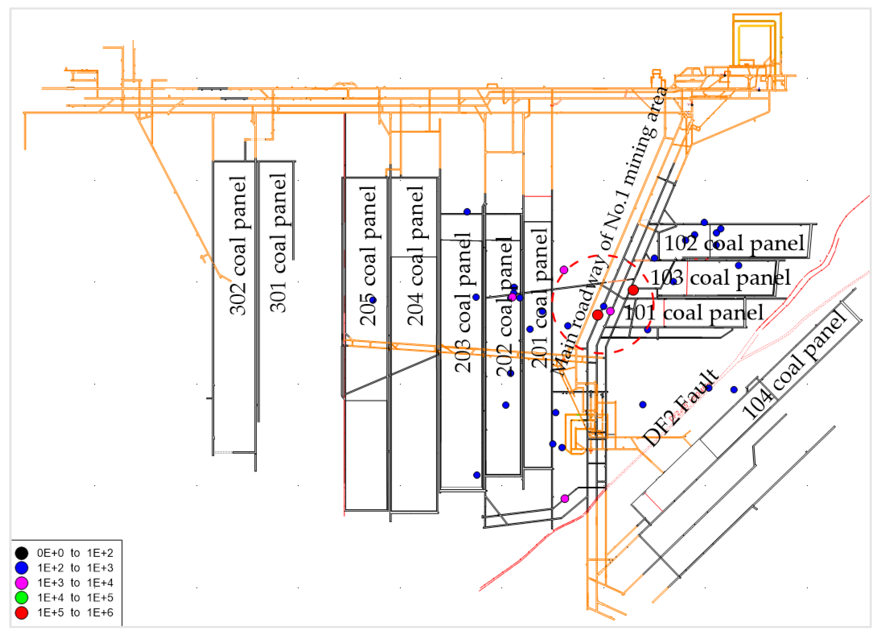
2. Engineering Geological Background

Located at the northwest of Binchang Mining Area in Shaanxi Province, China, Gaojiapu well field connects with Yangjiaping and Mengcun well fields in the south, extends to the Jinghe River in the north, adjoins Yadian mine in the east, and extends to the border between Shaanxi and Gansu in the west. The east-to-west length is approximately 25.7 km, and the south-to-north width is approximately 16.6 km. The field area is 219.1699 km2, and the average burial depth is 960 m. The administrative division of Gaojiapu well field is under the jurisdiction of Dizhang Village, Penggong Village, and Yuyuan Village of Wuxian County and Xianggong Town, Hongjia Village, and Liujiahe Village in Shaanxi Province. In this mine, 4# coal seam of Jurassic Yan’an formation is mainly exploited, with an average seam thickness of 10 m.
The main coal roadway in No.1 mining area of Gaojiapu Coal Mine is located at 4# coal seam, the roof coal is supported by 2 m, and the floor coal is retained by 2 m. The dynamic failure time (refers to the time from ultimate strength to complete failure of the coal specimen under uniaxial compression, expressed in “ms”, expressed in “DT”), impact energy index (refers to the ratio of the deformation energy accumulated before the peak value and the deformation energy loss after the peak value of the coal specimen under uniaxial compression, expressed in “KE”), elastic energy index (refers to the ratio of the elastic deformation energy to the plastic deformation energy of the coal specimen under uniaxial compression when the force reaches a certain value (before failure) and unloads, expressed in “WET”), and uniaxial compressive strength (RC) of coal mass at 4# coal seam in this coal mine were experimentally determined, calculated, analyzed, and compared with those specified in the PRC National Standard—Classification and Laboratory Test Method on Bursting Liability of Coal (GB/T25217.2-2010) [31], as shown in Table 1. The dynamic failure times of the higher slice of 4# coal seam and that of the lower slice were 278.4 and 303.4 ms, respectively, and the impact energy indexes were 3.20 and 2.98, respectively. The elastic energy indexes tested were 13.36 and 11.54, respectively, and the uniaxial compressive strengths were 20.47 and 18.18 MPa, respectively. In accordance with the single-index criterion, the dynamic failure time and impact energy index at the higher and lower slices of 4# coal seam showed a weak bursting liability. The elasticity energy index and uniaxial compressive strength manifested a strong bursting liability. The 4# coal seam had a strong bursting liability by combining these results. The test results of the bursting liability index at higher and lower slices of 4# coal seam are listed in Table 2.

3. Analysis Method and Numerical Simulation Scheme

3.1. Failure Mechanics Criteria for Surrounding Rock in Deep Roadway

The average value of three normal stresses is the average stress, which can be expressed by σ m as follows [32]:
σ m = 1 3 ( σ x + σ y + σ z ) = 1 3 ( σ 1 + σ 2 + σ 3 ) .
where σ x , σ y , and σ z are the principal stress components in the three directions of x, y and z, σ 1 , σ 2 , and σ 3 are the maximum principal stress, intermediate principal stress, and minimum principal stress.
The stress state at any point in the surrounding rock of the deep roadway can be decomposed into the sum of spherical stress and deviatoric stress. The tensor matrix of this model can be expressed as:
[ σ x τ x y τ x z τ y x σ y τ y z τ z x τ z y σ z ] = [ σ m 0 0 0 σ m 0 0 0 σ m ] + [ σ x σ m τ x y τ x z τ y x σ y σ m τ y z τ z x τ z y σ z σ m ] .
where τ i j is the shear stress and components in different directions.
S x = σ x σ m , S y = σ y σ m , S z = σ z σ m , S x = σ x σ m , S y = σ y σ m , and S z = σ z σ m … were set.
The deviatoric stress tensor can be denoted as:
[ σ x σ m τ x y τ x z τ y x σ y σ m τ y z τ z x τ z y σ z σ m ] = [ S x τ x y τ x z τ y x S y τ y z τ z x τ z y S z ] ,  
S i j = [ S x x S x y S x z S y x S y y S y z S z x S z y S z z ] .
where S x , S y , and S z are the deviator stress components in the three directions of x, y, and z, and S i j is the deviator stress tensor.
Under the corresponding coordinate system of the main axis, no shear stress is found on the main plane. Thus, the invariant of stress deviator can be expressed as principal stress.
J 1 = ( σ x σ m ) + ( σ y σ m ) + ( σ z σ m ) = 0 J 2 = 1 6 [ ( σ x σ y ) 2 + ( σ y σ z ) 2 + ( σ z σ x ) 2 ] J 3 = ( σ x σ m ) ( σ y σ m ) ( σ z σ m ) .
where J1, J2, and J3 are the first, second, and third invariants of deviatoric stress tensor, respectively.
The plastic failure will be generated to the surrounding rock of roadway when the maximum principal deviatoric stress, which plays a dominant role in the stress deviator, exceeds the ultimate strength of the coal and rock mass. The maximum principal deviatoric stress can be denoted as:
σ 1 = 2 3 σ 1 1 3 ( σ 2 + σ 3 ) .  
Pan et al. [33] pointed out that when the rock mass is hardened or softened under a complicated stress state, the deviatoric stress is sensitive to the change in the load-bearing properties of surrounding rock in the roadway by assuming that the volumetric strain of the rock mass is zero. The variation trend of deviatoric stress becomes a key parameter determining the plastic failure of surrounding rock in the roadway. Before the excavation, the surrounding rock is under a hydrostatic pressure state, and the deviatoric stress is zero. Excavation is an unloading process of rock mass, breaking the balance of stress field in primary rock. Thus, the stress field is redistributed in a certain zone, and deviatoric stress is generated in the surrounding rock. The stress field is redistributed in the surrounding rock of the roadway after the dynamic load disturbance. The plastic failure occurs when the maximum principal deviatoric stress σ 1 exceeds the strength limit of the rock mass.

3.2. Failure Energy Criteria for Surrounding Rock in Deep Roadway

The energy change runs through the whole rock deformation process, and energy is the prime power for material failure. In reality, the energy input affected by various defects inside the rock causes the valence bond rupture between some particles so as to cause the structural deformation failure. In the complicated and intense geostatic stress and tectonic stress fields, underground rock mass experiences simultaneous changes in volume and shape under external force. The elastic strain energy inside the rock mass is divided into distortion energy formed by the shape change and volumetric energy formed by the volume change. The elastic strain energy is calculated with the following formula:
U = U d + U v
where U is the elastic strain energy, Ud is the distortion energy, and Uv is the volumetric energy.
However, the main factor leading to the plastic deformation of a material is distortion energy but not the whole elastic strain energy. In accordance with Mises [34] yield condition (also called condition of distortion energy), the material at this point starts yielding when the distortion energy Ud corresponding to the stress state at one point within the object reaches an ultimate limit value Uk. Plastic mechanics theory states that the volumetric change is elastic. Thus, the volumetric strain of the object is zero, or the average normal strain is zero during the plastic deformation process [35]. Therefore, only the shape change is considered, and the volume change is ignored when the surrounding rock of roadway experiences a plastic failure. From the angle of force and deformation, the formula of distortion energy is as follows:
U d = J 2 2 G
where G is the shear modulus; J2 is the second invariant of deviatoric stress tensor.
As shown in Equation (9), the change in distortion energy is closely related to the deviatoric stress. Under the linear elastic circumstance, the distortion energy density of microunit body under spatial stress state can be expressed as:
U d = 1 + μ 6 E [ ( σ 1 σ 2 ) 2 + ( σ 2 σ 3 ) 2 + ( σ 3 σ 1 ) 2 ] .
where E   is the elasticity modulus;   σ 1 is maximum principal stress; σ 2   is the intermediate principal stress;   σ 3 is the minimum principal stress;   μ is the Poisson’s ratio.
The plastic failure of surrounding rock is actually the rock failure formed under the joint action of deviatoric stress and distortion energy. Dissipated energy leads to rock damage and the weakening and loss of material strength. The instantaneous release of distortion energy results in rock failure. The energy dissipation is one way and irreversible, whereas the energy release is two-way and is reversible only if one condition is met [36,37]. Plastic deformation absorbs the deformation energy, prevents crack propagation, and impedes the fracturing to some extent [38,39]. Hence, the total elastic strain energy U accumulated in the surrounding rock system is largely divided into three parts: (1) One part of elastic strain energy is consumed or absorbed by the relative slippage of the joint plane and generation and propagation of secondary cracks at the tip of original crack or dissipated in other forms, such as heat energy, recorded as Un; (2) one part of elastic strain energy facilitates the plastic failure of coal and rock mass and is dissipated in the form of plastic energy, recorded as Uk; (3) one part of elastic strain energy is the residual energy after the failure of coal and rock mass and serves as the initial kinetic energy for the burst of broken coal and rock mass, recorded as ΔU.
The energy criterion for the impact failure of surrounding rock in the roadway is obtained as below.
ΔU = UUnUk > 0
The distortion energy Ud is the energy needed to reach the minimum failure of coal and rock mass. When ΔU = 0, the coal and rock mass goes through slow and approximately static failure. When ΔU > 0, a dynamic failure is generated, and the broken coal and rock mass can fly out toward the unloading direction due to ΔU. Specifically, ΔU is transformed into the kinetic energy of rock mass, thereby forming the impact of coal and rock mass.

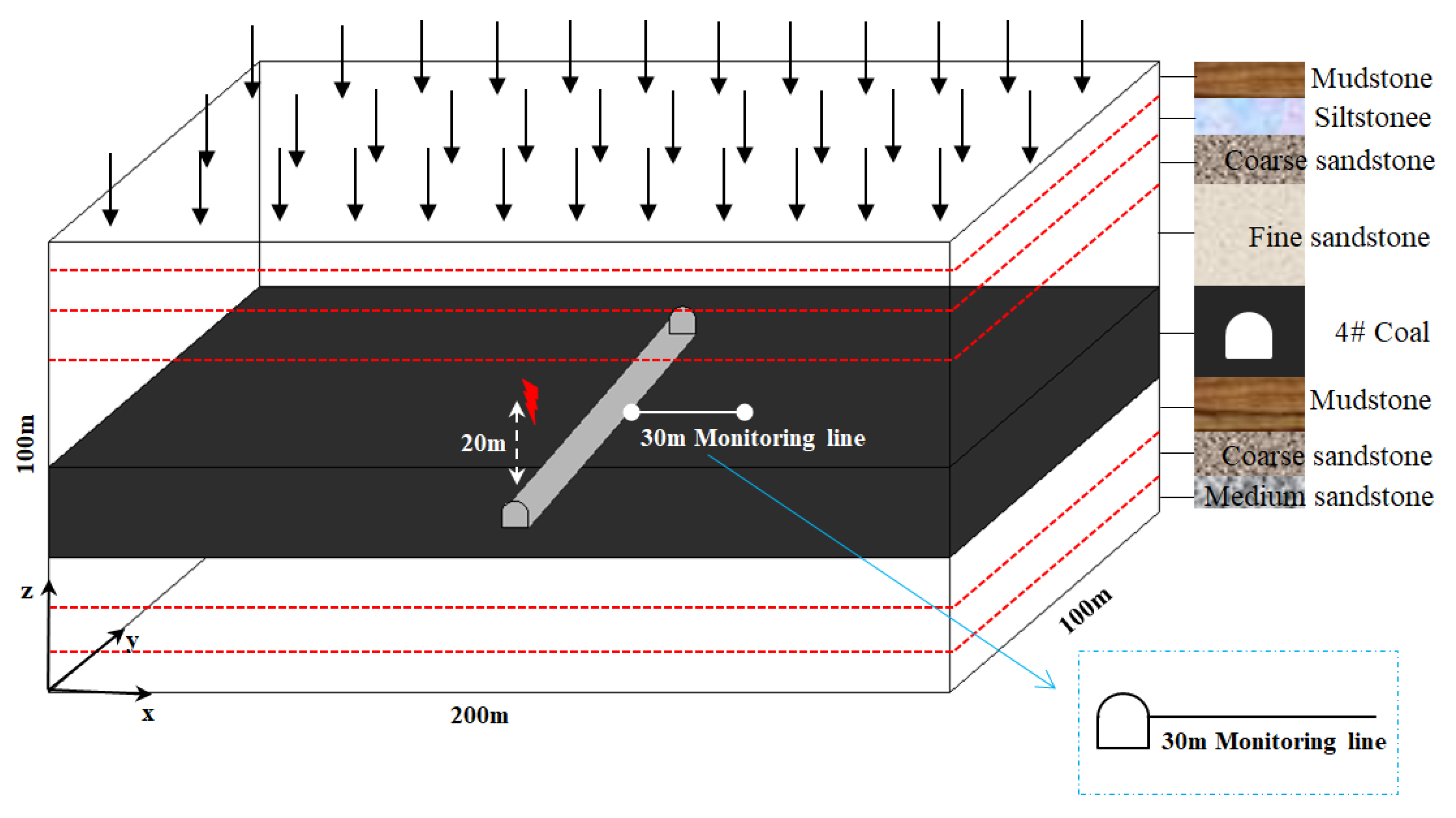
3.3. Establishment of Numerical Model

The main coal roadway in No.1 mining area of Gaojiapu Coal Mine was taken as the simulation object. A numerical model with dimensions of 200 m × 100 m × 100 m (Figure 1) was established via FLAC3D (FLAC3D 5.00, Itasca International Inc., Minneapolis, MN, USA). The roadway section was a vertical wall-like semi-arched shape, the roadway width was 5.8 m, the wall height was 3 m, and the arch height was 2 m. A total of 722,975 elements were divided. The values of physical and mechanical parameters of surrounding rock in the model are listed in Table 3. The Mohr–Coulomb failure criterion was adopted, and the boundary conditions were determined as follows:
(1) The displacement boundary constraint was applied to the model perimeter. The velocities in the x-direction at the left and right boundaries, in the y-direction at the front and rear boundaries, and those in the x, y, and z directions at the bottom boundary were zero.
(2) The upper boundary of this model was a free boundary, and a vertical uniformly distributed load was applied to simulate the self-weight load of overlying strata. Given the influence of self-weight of this model, the self-weight load of overlying strata applied was 22.5 MPa.
(3) The geostatic stress field was applied to this model, and the gravitational acceleration was taken as 9.81 m/s2.
Xu [40] the waveform features of roof rupture and fault activation events were acquired through microseismic monitoring. In accordance with elastic wave theory, any complicated stress wave can be obtained through Fourier transform of several simple harmonic waves; that is, a simple harmonic wave is the basic form of an underground complicated stress wave. Lu [41] pointed out that the vibration recorded by microseismic monitoring in the case of field rock burst only lasted for dozens of milliseconds, and the rock burst was not of multi-round impact effect. If the impact vibration source wave is simplified into a simple harmonic wave, the principal frequency of mine earthquake is 10–20 Hz or so with a period of 0.05–0.1 s. In this simulation, the dynamic load applied to cause the impact failure of coal mass lasted for approximately one period. The microseismic distribution on the day of burst is shown in Figure 2. In accordance with the spatial coordinates and energy of the microseismic event monitored on that day, the dynamic module in FLAC3D was used to apply a simple harmonic stress wave 20 m above the roadway to perform the equivalent simulation of a mine earthquake with an intensity of 106 J. The intensity and frequency of earthquake focus were set to 48 MPa and 20 Hz, respectively, and the dynamic load simulated lasted for one period (0.05 s). The action time of dynamic load was 0.2 s, and a horizontal monitoring line (Figure 1) was arranged at the roadway wall to monitor the changes in the stress and energy at the roadway wall. The energy gradually dissipated with the expansion of the stress-strain hysteretic loop, and a Rayleigh damping parameter was set for this model. This process was performed to make the simulation environment accord with the field environment to a great extent.

4. Results and Discussion

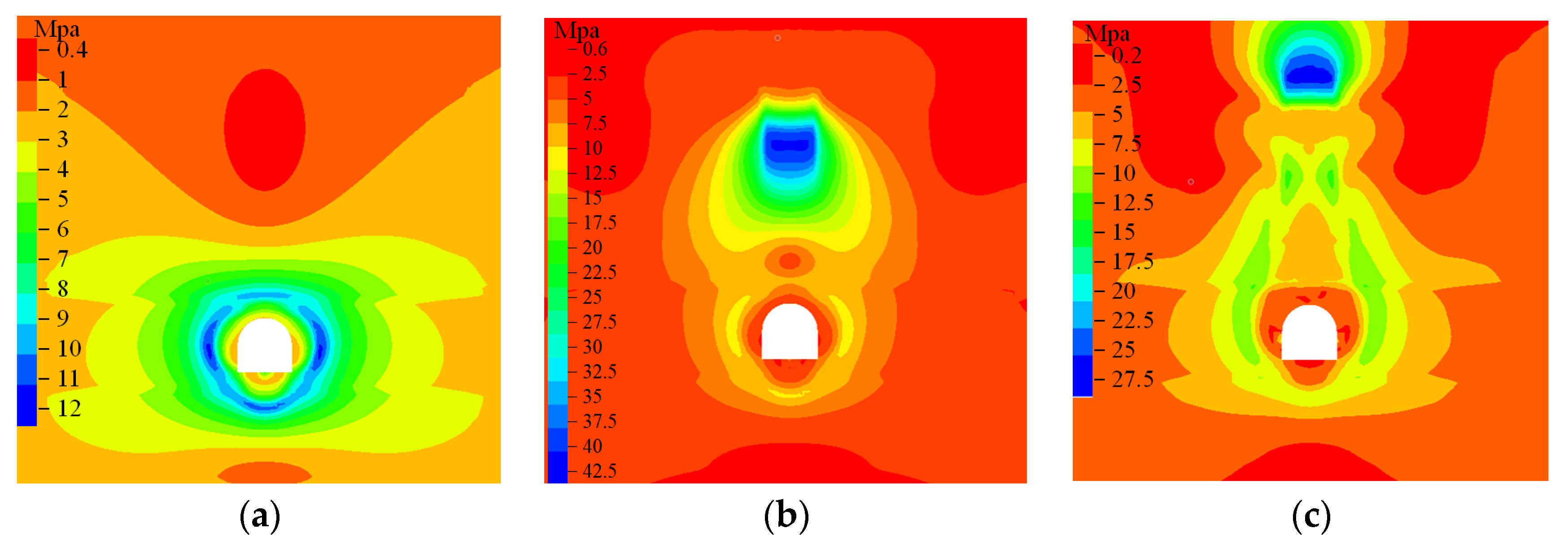
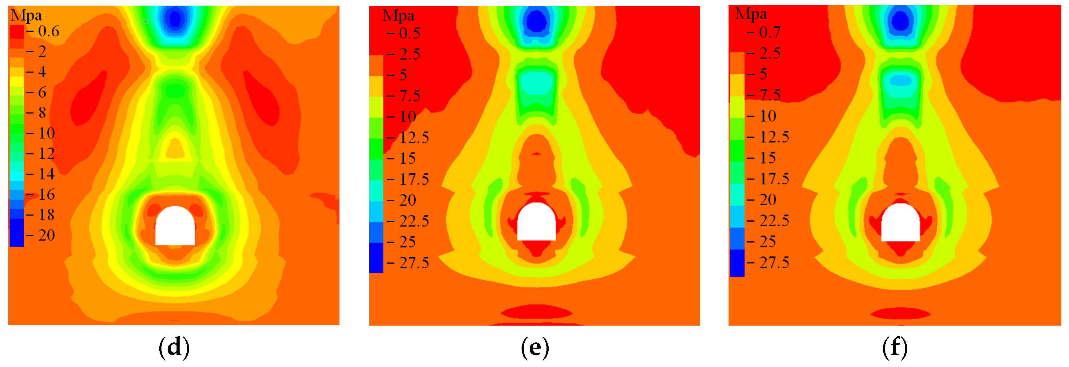
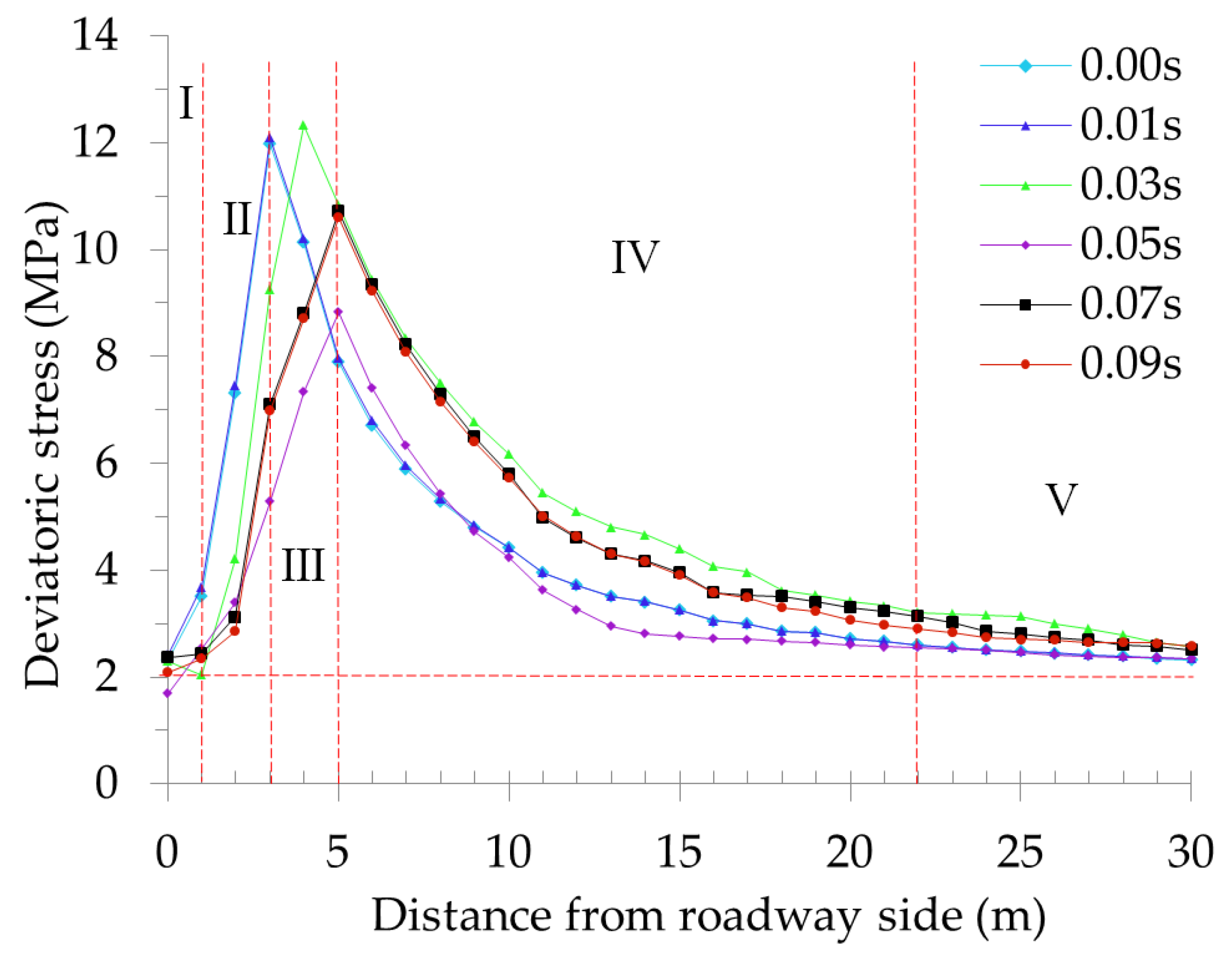
4.1. Spatial-Temporal Evolution Laws of Deviatoric Stress Field

The dynamic evolution of maximum principal deviatoric stress distribution around the roadway with the disturbance time of dynamic load is shown in Figure 3. The dynamic evolution curves of maximum principal deviatoric stress in the surrounding rock of the roadway are displayed in Figure 4.
As shown in Figure 4, an annular stress zone (Figure 3a) was formed at 3 m of the roadway perimeter after the excavation unloading. When the dynamic load disturbance was generated at the roof, a core stress zone was formed in the center of earthquake focus, where the maximum value deviatoric stress reached as high as 40 MPa. When the dynamic load acted for 0.01 s (Figure 3b), the dynamic load stress wave started propagating downward. However, the deviatoric stress value at two walls of the roadway was not obviously changed and mostly overlapped with the evolution curves of deviatoric stress in the surrounding rock of the roadway before the dynamic load disturbance. This condition indicated that the dynamic stress wave did not propagate to the roadway. The surrounding rock in zone I was close to the free space of the roadway, and the deviatoric stress aggravated the failure degree of the surrounding rock. The deviatoric stress first declined with the curve shifting down. At 0.03 s of dynamic load action (Figure 3c), the deviatoric stress at two walls of the roadway was transferred from shallow surrounding rock to the deep part, and the peak point shifted backward. The deviatoric stress reached as high as 12.5 MPa under the dual influences of roadway excavation and dynamic load stress wave. The cracks in the surrounding rock of zones II and III were incompletely developed with a great attenuation coefficient, which militated against the stress transmission, and the deviatoric stress acted on the surrounding rock, leading to its yield failure. Subsequently, the deviatoric stress presented a declining trend, and the decrease amplitude was larger than that in zone I. At 0.05 s (Figure 3d), the dynamic load stress wave acted on the surrounding rock in the whole roadway and formed a stress ring in which the deviatoric stress progressively increased from the inside to the outside. As shown in Figure 4, the deviatoric stress inside the surrounding rock beyond 30 m away from the roadway wall was gradually stabilized and approached a deviatoric stress value (2 MPa) before the dynamic load. From the macroscopic angle, the deviatoric stress in the surrounding rock of the roadway was redistributed within the 30 m range of two walls after the dynamic load disturbance was generated. However, the deviatoric stress sharply increased, reached its peak point, and then suddenly dropped within the 5 m range of the roadway wall. The surrounding rock in the roadway was extremely susceptible to instability failure due to the dynamic and static load superposition at the border between zones III and IV. Subsequently, the stress state of primary rock was approximated increasingly, followed by a relatively stable phase.

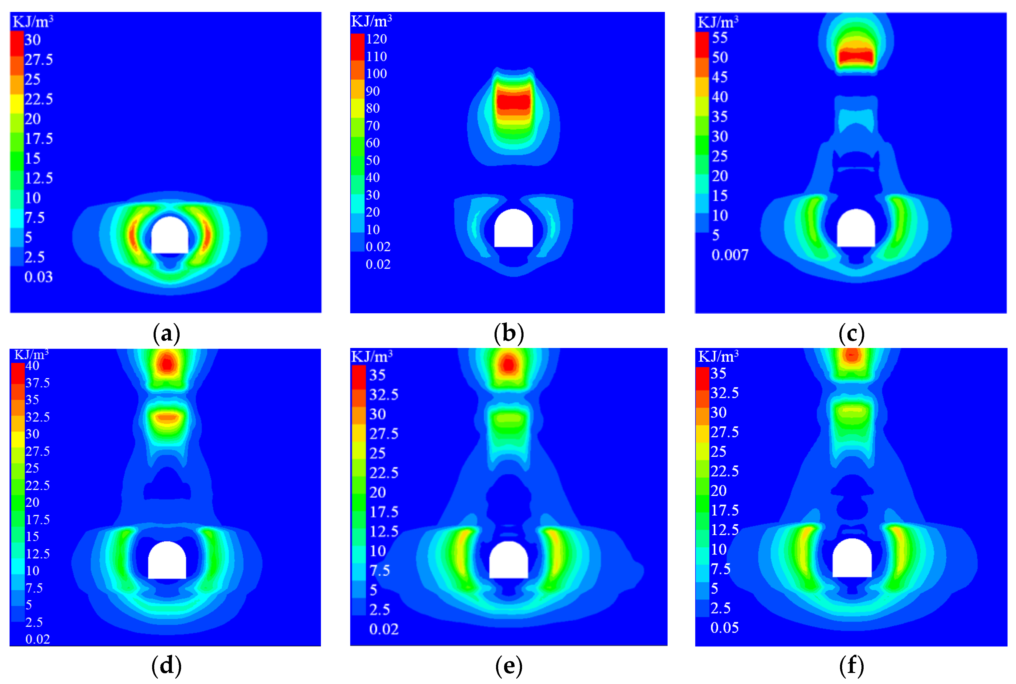
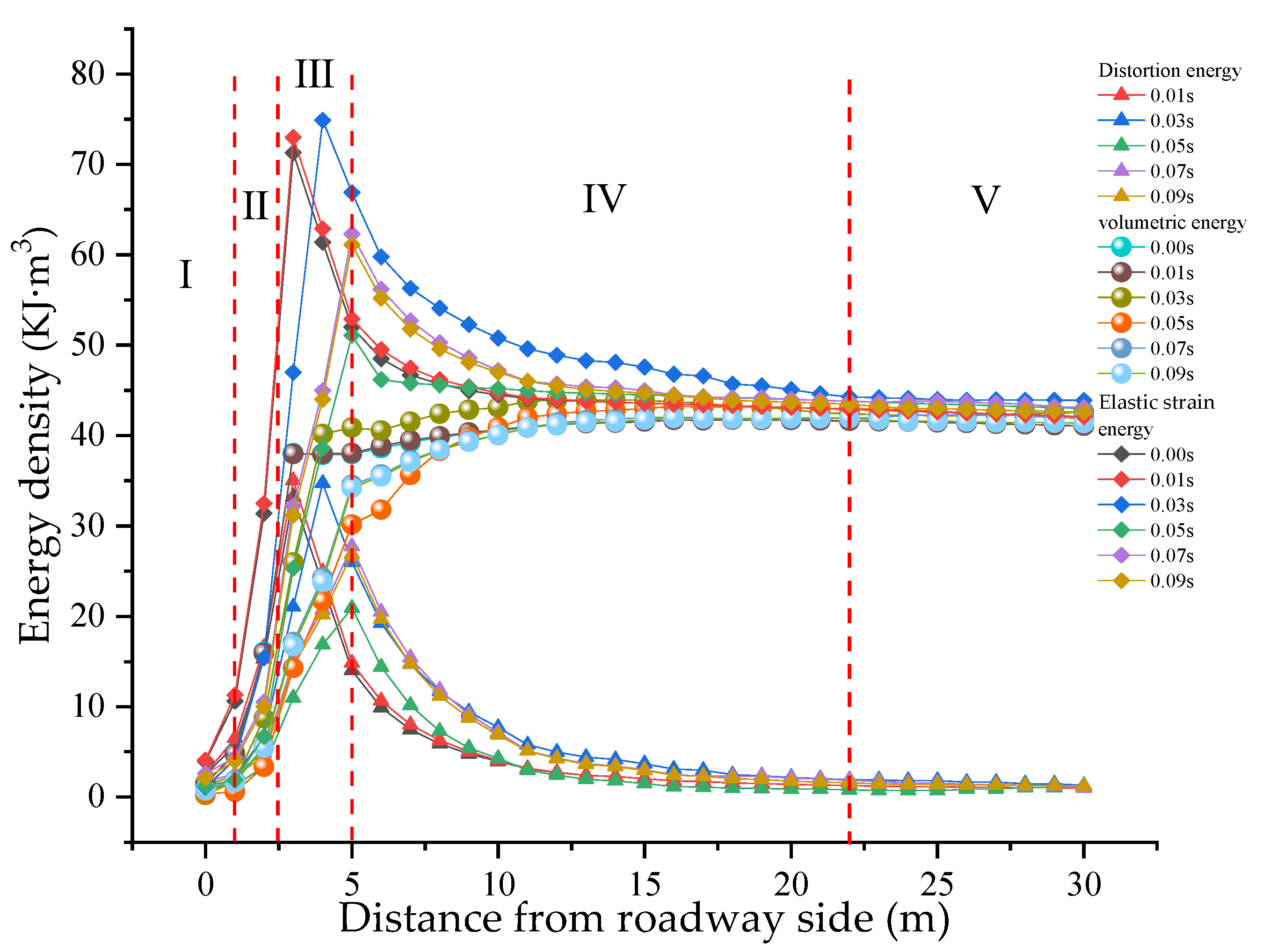
4.2. Spatial-Temporal Evolution Laws of Distortion Energy Field

Rock burst is an instantaneous energy release process of surrounding rock in the roadway. The distortion energy density, volumetric energy density, and elastic energy density of surrounding rock were extracted by programming on FISH language. The evolution nephogram of the distortion energy of surrounding rock under the dynamic load disturbance is shown in Figure 5. The dynamic evolution curves of the energy density of surrounding rock under the dynamic load disturbance are displayed in Figure 6.
As shown in Figure 5, the distortion energy around the roadway presented approximately annular distribution, and a circle of low-energy belts was formed on the roadway surface close to the free space before the dynamic load disturbance (Figure 5a). Impacted by the excavation, the floor failure was serious at the two walls of the roadway, and the distortion energy was released greatly. As manifested in the nephogram, the low-energy zone of 2 m floor coal was obviously larger than that at the two walls of the roadway, and an energy concentration zone was formed at 4–5 m of the surrounding rock at two walls. After the dynamic load disturbance was applied (Figure 5b), the main core energy zone was formed in the center of the earthquake’s focus. The distortion energy in surrounding rock was not obviously changed, which was largely identical with the energy evolution curves before the application of dynamic load. When the dynamic load acted for 0.03 s (Figure 5c), the energy concentration zone was enlarged at the two walls, and the stress wave generated by the dynamic load disturbance propagated to the two walls. As shown in Figure 6, the peak values of distortion energy and elastic energy reached 35 and 75 KJ/m3, respectively. Subsequently, the energy field was shifted toward the deep part, and the curve shifted backward. When the action time of dynamic load was lengthened to 0.05 s (Figure 5d), a secondary core energy zone was derived beneath the main core energy zone in the center of earthquake focus. The peak value of distortion energy was 37.5 KJ/m3, and the distortion energy at two walls shifted toward the floor, which was manifested by the downward shift of the peak point of the curve. With the increase in disturbance time of dynamic load (0.07–0.09 s), the distortion energy in the secondary core zone was reduced and propagated continuously downward, whereas the distortion energy at the two walls rose again, as shown in Figure 5e,f. The surrounding rock was seriously damaged in zone I, with low stress-value and small accumulated energy by analyzing the energy redistribution zones after the dynamic load disturbance. These conditions were manifested by the downward shift of the curve. Zones II and III were located in the high-stress region of surrounding rock in this roadway, and the attenuation amplitude was small in the energy propagation process. Thus, the energy in the two zones was increased more greatly than that in zone I. The distortion energy and elastic energy suddenly dropped at the border between zones III and IV, indicating that the energy release nearby the peak stress zone was the main energy source for the failure of surrounding rock in the roadway. However, the volumetric energy was increased rather than reduced, proving that the volumetric energy was unrelated to the plastic failure of coal and rock mass. Zone V entered the deep surrounding rock, where the distortion energy was approximately zero, and the elastic energy was mainly volumetric energy. Thus, the plastic failure did not occur.
In accordance with Equation (7), the volumetric energy was the difference value between elastic energy and distortion energy. When the energy loss was ignored, the volumetric energy in zones I, II, III, and IV was the residual energy ΔU of broken coal and rock mass. ΔU is approximately one-half of the total elastic strain energy and is the initial kinetic energy for its burst.

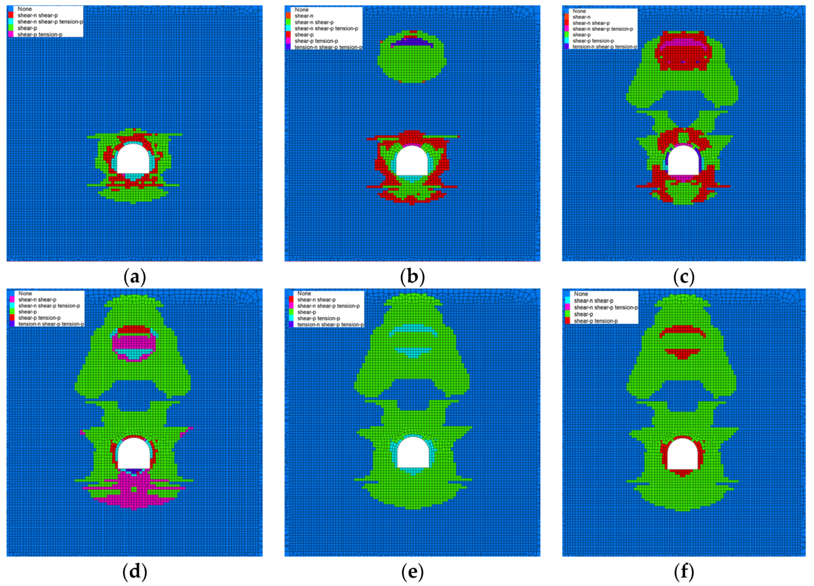
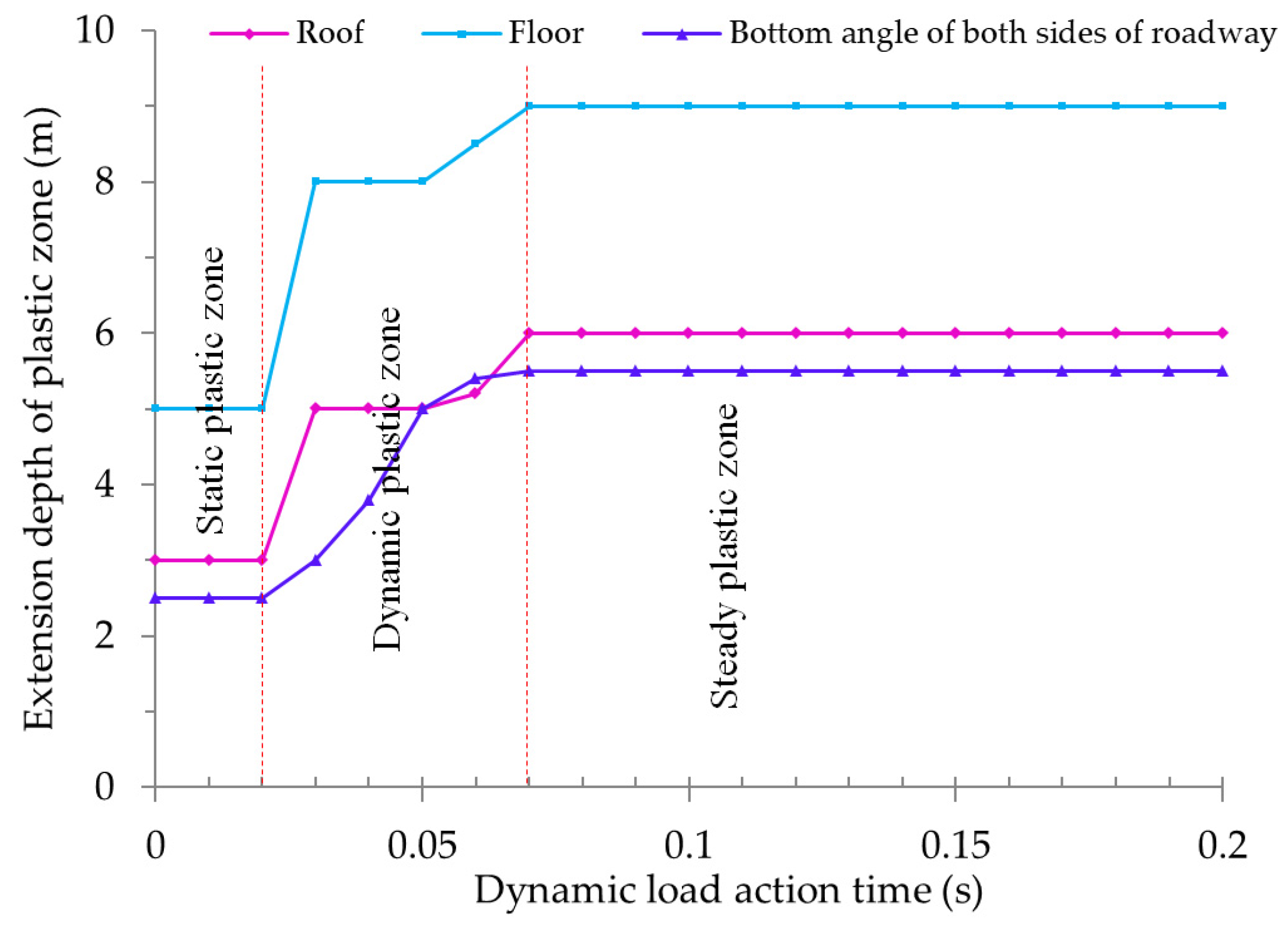
4.3. Spatial-Temporal Evolution Laws of Failure Field

The evolution nephogram of the plastic zone in surrounding rock with the dynamic load disturbance is shown in Figure 7. The variation tendency chart of the expansion depth of the plastic zone in the action of dynamic load disturbance is displayed in Figure 8.
As shown in Figure 7, following the roadway excavation, the unloading disturbance broke the stress field of primary rock, and the stress was redistributed. The deviatoric stress was generated, leading to a failure of surrounding rock within the 2–5 m range at the roadway perimeter. The load-bearing capacity was weak, and the floor failure was the most serious, with the largest failure depth because floor coal was retained in the roadway. The coal and rock mass close to the free space of the roadway experienced a shear failure. When the dynamic load disturbance acted for 0.01 s, the deviatoric stress and energy of surrounding rock around the roadway were mostly unchanged, the plastic zone was not expanded, and this phase was called static plastic zone (0.00–0.02 s). The dynamic stress wave first arrived at the upper corner position (0.03 s) of two walls, with a horizontal distance from the roadway wall of approximately 4 m. This zone was in the peak zone of deviatoric stress, and an obvious failure occurred at the upper corner position. The plastic zone was expanded to a depth of 6 m, and two “horn-like” plastic zones were formed, as shown in Figure 7c. With the sudden energy release, the rock mass experienced a failure in this phase, the plastic zone was expanded at high speed, and a dynamic plastic zone was formed. The deviatoric stress was small in the zone 3–10 m above the roadway. The distortion energy was approximately zero in this zone and was located in a “distortion energy vacuum zone.” The strength limit of rock mass was not reached. Thus, the rock mass did not experience any plastic deformation. With the continuous downward propagation of dynamic load stress wave to the roadway floor, the deviatoric stress and distortion energy at the floor sharply increased, reaching the yield condition of the rock mass. The floor surface experienced tensile shear failure, and the deep part of the floor went through the shear failure repeatedly. The plastic zones were continuously increased in the floor, and an “arc-shaped” outer contour (0.05 s) was formed. An approximately “spherical” shear failure (Figure 7d) was generated above the roof due to the formation of a secondary distortion energy core zone. Penetrating into the surrounding rock by 20 m, the distortion energy slowly tended to be zero, the plastic deformation was approximately zero, and the elastic deformation played a dominant role. During 0.07–0.09 s of dynamic load action, the local distortion energy and deviatoric stress concentration zones reached the yield limit of the rock mass. The rock mass experienced repeated shear and tensile failures, the overall dynamic plastic zone was no longer increased, and a steady-state plastic zone was formed. When the static plastic zones were instantaneously increased and evolved into dynamic plastic zones, the plastic zones in the roof and floor were arc-shaped. The maximum depth of plastic zone appeared close to the upper corner of the roof at the two walls and below the floor. The shear and tensile failures played a dominant role on the roadway surface; however, the shear failure dominated in the deep part.
The above analysis indicated that the energy could not be accumulated in zone I, indicating that many cracks were found in the coal and rock mass. The stress wave had a large attenuation coefficient when propagating in this zone. Thus, zone I was broken zone. Zone II was the original plastic zone in which the failure was caused by the roadway excavation unloading before the dynamic load disturbance. Zone III was expanded on the basis of the original plastic zone under the influence of dynamic load disturbance and was a newly added plastic zone. The stress-energy suddenly dropped at the border between zones IV and III. This position was determined as an elastic-plastic junction point, and zone IV was a elastic zone. The stress and energy tended to stable values in zone V, which was the stress zone of primary rock. The evolution process of impact failure in the surrounding rock of this roadway under the dynamic load disturbance was obtained as follows: stress wave generated under the dynamic load disturbance at the roof →energy consumed due to the damage of surrounding rock (Un) →energy consumed due to instantaneous expansion of plastic zone in surrounding rock (Uk) →instantaneous release of residual energy in the broken coal and rock mass (ΔU = Un) →burst of coal and rock mass.

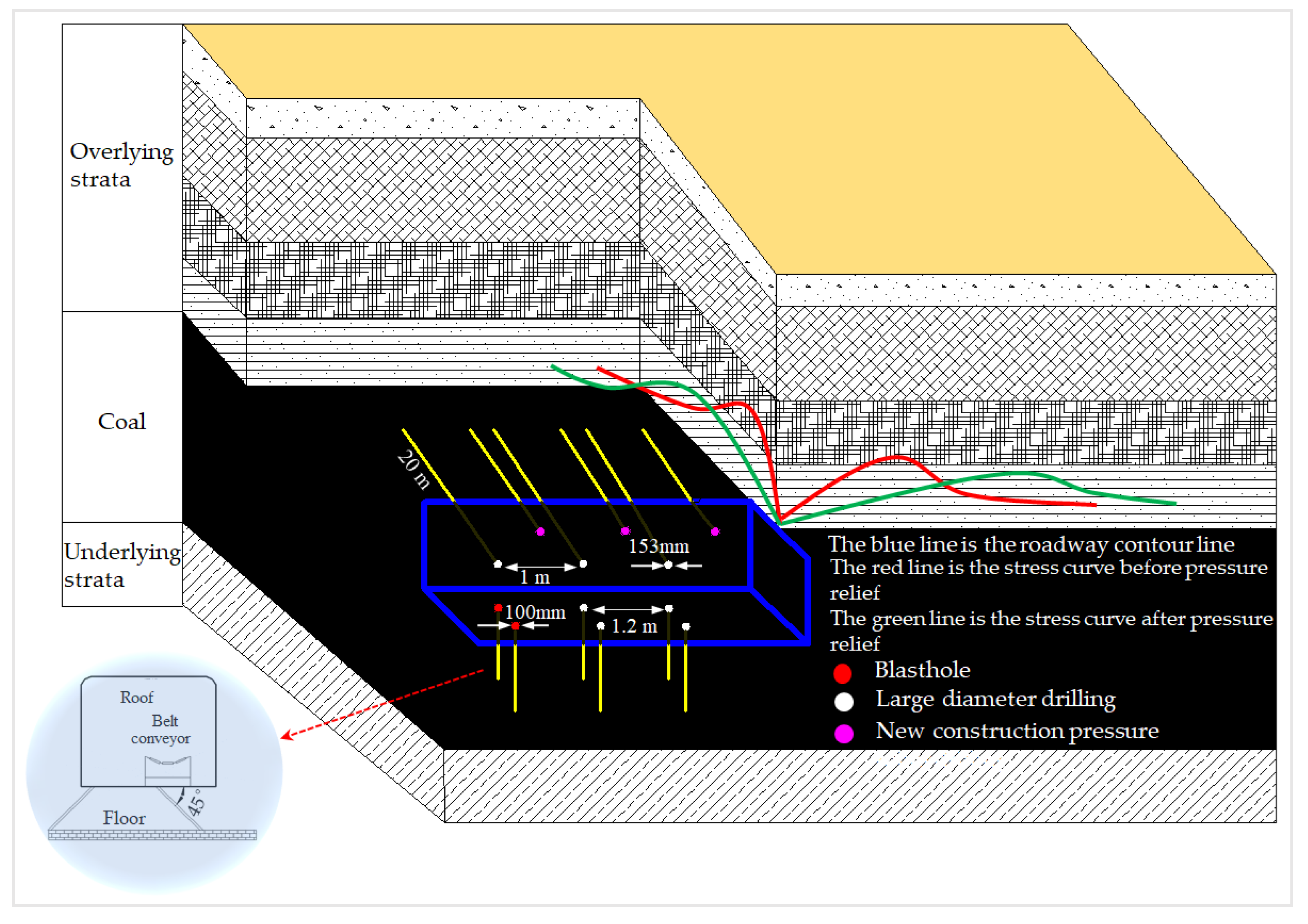
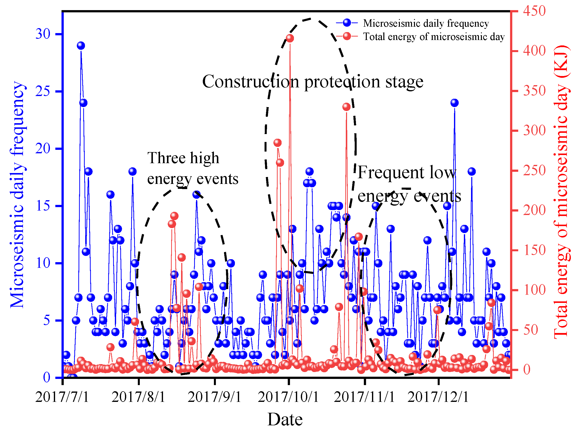
5. Optimization of Prevention and Control Measures for Rock Burst and Effect Evaluation

The stress change in the coal-rock system was synchronous with the energy accumulation and release; that is, the stress increase was accompanied by the energy accumulation and release. The high stress concentration was the basis, and the dynamic load stress wave was the inducement. For the surrounding rock that reached or was about to reach the critical conditions for the failure under the concentrated stress of high static load, slight dynamic load disturbance instantaneously increased the stress level in the coal and rock mass. The coal-rock system experienced a failure because its strength limit was reached, and the rock burst was due to the instantaneous energy release.
In accordance with the above analysis, the dynamic load stress wave generated at the rock strata of the roadway roof resulted in the early concentration of stress and energy at the two walls and development toward the floor. The early-stage analysis results were summarized by means of dynamic monitoring via the present microseismic SOS system in the coal mine. The optimization parameters of prevention and control measures for rock burst were proposed. The practical microseismic monitoring results and field situation were combined to evaluate their preventive and controlling effect.
The prevention and control of the main roadway in No.1 mining area are mainly aimed at the following two aspects.
(1) Reduce the strength and stress concentration degree of surrounding rock or transfer the peak stress zone to the deep part of rock mass for weakening the coal and rock mass nearby the main roadway;
(2) Mitigate the dynamic disturbance to the coal and rock mass under the high static load stress condition and reduce the occurrence degree of rock burst to reduce the dynamic load energy generated.
Major-diameter (153 mm) holes were drilled at the two walls of the roadway at the coal seam in No.1 mining area for the pressure relief of the coal mass at the walls. Their angle was perpendicular to the coal wall, and they were 1.2–1.6 m away from the floor. The length was 20 m, and the spacing was 1.0 m. Three drill holes were arranged at one row, and the hole sealing length was greater than 2 m. Major-diameter holes were drilled once again in the zone with rock burst risk for pressure relief, and the holes presented a three-petal-like arrangement with the original major-diameter drill holes. The depressurization holes were staggered with blast holes at the floor of the main roadway at the coal seam in No.1 mining area. One blast hole was first constructed, followed by two major-diameter drill holes. The subsequent construction was implemented similarly. The hole spacing was 1.2 m, and the diameter of the depressurization hole was 153 mm, and that of the blast hole was 100 mm. The dip angle of the drill hole was −45°, and the hole depth was ensured until the rock was naked by penetrating the coal seam at the floor. Two-row drill holes were totally constructed on the floor. The layout plan of major-diameter depressurization holes and blast holes in the main roadway is shown in Figure 9.
The microseismic activity can reflect the rupture status of coal and rock mass. Thus, the preventive and controlling effect on the rock burst of the working face can be largely determined on the basis of the time-dependent changes in large-energy microseismic events, where its significant reduction marks the decreasing quantity of dangerous mine earthquakes [42]. The main roadway in No.1 mining area was selected as the statistical zone. This roadway was protected in the construction during October 2017, and the data in August and September 2017 were chosen and compared with those in November and December 2017 to avoid the influence of construction on the statistical results. In August 2017, 173 effective mine earthquakes were monitored in the main roadway zone of No.1 mining area, where the maximum energy was 1.93 × 10⁵ J, and 137 effective mine earthquakes were monitored in September, where the maximum energy was 2.85 × 10⁵ J. In November 2017, 199 effective mine earthquakes were monitored, where the maximum energy was 9.81 × 10⁴ J, and 266 effective mine earthquakes were monitored in December, with the maximum energy of 7.49 × 10⁴ J.
As shown in Figure 10, the vibration with energy of 105–106 J occurred now and then before the depressurization measures were taken. However, the total quantity of microseismic events was larger, indicating that the used depressurization scheme reached a good effect. This condition was because the elastic energy of surrounding rock in the roadway was released in the form of small-energy microseismic (<104 J), thereby reducing the probability of large-energy mine earthquakes and further lowering the occurrence probability of rock burst.

6. Conclusions

The stress of coal and rock mass has a linear relationship with depth, and the stored elastic strain energy of coal and rock mass has a quadratic relationship with depth. The greater the burial depth, the greater the stress condition of the coal and rock mass, the greater the stored elastic strain energy, the more energy remaining after the coal rock is destroyed, and the more severe the rock burst occurs. Therefore, energy is more sensitive to the changes in depth and is a key factor in studying the formation mechanism of rock bursts in wells with a depth of one thousand meters. Many scholars have conducted qualitative research on energy in the macroscopic sense, but few studies have been reported on the energy that causes the destruction of coal and rock masses and the energy that causes the impact of broken coal and rock masses. On the basis of the achievements harvested by predecessors and under the engineering background of the main roadway in No.1 mining area of Gaojiapu Coal Mine in Binchang Mining Area, Shaanxi Province, China, the energy in the rock burst process of coal and rock mass was semiquantitatively studied. After the necessary theoretical analysis, the deviatoric stress field and distortion energy field in the surrounding rock of deep roadway and the spatial-temporal evolution laws of plastic zones under the dynamic load disturbance were simulated and analyzed via the built-in dynamic module of FLAC3D. The “force-energy criterion” for the failure of surrounding rock in such a deep roadway and the “energy criterion” for the rock burst were established. The impact failure mechanism of the surrounding rock was revealed.
The results show that after the dynamic load disturbance, the partial stress and distortion energy are concentrated in the shallow part at two walls of the roadway in the early phase. With the continuous propagation of dynamic load stress wave, the partial stress and distortion energy are transferred to the deep part. The sudden high-energy release occurred in the peak zone of partial stress, leading to the plastic failure of coal and rock mass. Subsequently, the distortion energy was fully accumulated in the original plastic zone and transferred from shallow surrounding rocks to the deep surrounding rocks in the roadway, where the partial stress and distortion energy of coal and rock mass satisfy the “force-energy criterion.” Thus, the original plastic zone was sharply expanded, thereby forming a new plastic zone. The coal and rock mass experienced an approximately static failure when no residual energy (ΔU) was found in it. When ΔU > 0, the rock mass went through dynamic failure, and ΔU was mainly the volume transformation energy, which is approximately one-half of the total elastic strain energy. ΔU was transformed into the initial kinetic energy of broken coal and rock mass. Thus, the coal and rock mass are burst out. In severe cases, this condition was manifested by the rock burst in the main roadway.
In accordance with the study results, the optimization scheme of preventive and control measures for rock burst was proposed, and the microseismic activity regularities before and after the depressurization were compared. The comparative results show that the prevention and control measures reach a good depressurization effect on the main roadway in No.1 mining area, thereby effectively reducing the high-stress and high-energy concentration degree in the roadway. The study results can lay a certain foundation for predicting and preventing the rock burst in coal mines by actively regulating the disaster-pregnant environment and mitigating the disaster-inducing conditions.

Author Contributions

Writing—Original draft, P.G. and J.L.; formal analysis, P.G. and J.L.; software, P.G. and J.C.; data curation, S.S., H.C., W.X., and W.Z.; Writing—Review & Editing, P.G. and J.L.; Source of funds, J.L. All authors have read and agreed to the published version of the manuscript.

Funding

This research was supported by the National Natural Science Foundation of China (52004004) and the China Postdoctoral Science Foundation of China (2019M661991).

Data Availability Statement

No new data were created or analyzed in this study. Data sharing is inapplicable to this article.

Conflicts of Interest

The authors declare no conflict of interest.

References

  1. Teng, J.; Qiao, Y.; Song, P. Analysis of exploration, potential reserves and high efficient utilization of coal in China. Acta Geophys. 2016, 59, 4633–4653. [Google Scholar]
  2. Wang, H.; Shao, M.; Wang, G.; Deng, D. Characteristics of stress evolution on the thrust fault plane during the mining. J. China Coal Soc. 2019, 44, 2318–2327. [Google Scholar]
  3. Li, J.; Guo, P.; Yuan, A.; Zhu, C.; Zhang, T.; Chen, D. Failure characteristics induced by unloading disturbance and corresponding mechanical mechanism of the coal-seam floor in deep mining. Arab. J. Geosci. 2021, 14, 1–14. [Google Scholar] [CrossRef]
  4. Miao, X.; Jiang, F.; Wang, C.; Deng, J. Study on Microseism-induced rock burst revealed by microseismic monitoring. Chin. J. Geotech. Eng. 2011, 33, 971–976. [Google Scholar]
  5. Zhao, T.-B.; Guo, W.-Y.; Tan, Y.-L.; Yin, Y.-C.; Cai, L.-S.; Pan, J.-F. Case Studies of Rock Bursts Under Complicated Geological Conditions During Multi-seam Mining at a Depth of 800 m. Rock Mech. Rock Eng. 2018, 51, 1539–1564. [Google Scholar] [CrossRef]
  6. Lv, J.G.; Wang, T.; Ding, W.B. Induction mechanisms of coal bumps caused by thrust faults during deep mining. J. China Coal Soc. 2018, 43, 405–416. [Google Scholar]
  7. Li, Z.-H.; Dou, L.-M.; Lu, C.-P.; Mu, Z.-L.; Cao, A.-Y. Study on fault induced rock bursts. J. China Univ. Min. Technol. 2008, 18, 321–326. [Google Scholar] [CrossRef]
  8. Wang, C.; Cao, A.; Zhu, G.; Jing, G.; Li, J.; Chen, T. Mechanism of rock burst induced by fault slip in an island coal panel and hazard assessment using seismic tomography: A case study from Xuzhuang colliery, Xuzhou, China. Geosci. J. 2017, 21, 469–481. [Google Scholar] [CrossRef]
  9. Gao, K.; Liu, Z.; Liu, J.; Zhu, F. Propagation law and failure characteristics of blasting stress wave in structural belt coal-rock. J. China Coal Soc. 2018, 43, 79–86. [Google Scholar]
  10. Wang, S.; Zhu, G.; Zhang, K.; Yang, L. Study on Characteristics of Mining Earthquake in Multicoal Seam Mining under Thick and Hard Strata in High Position. Shock. Vib. 2021, 2021, 6675089. [Google Scholar] [CrossRef]
  11. Qi, F.; Yang, D.; Zhang, Y.; Hao, Y. Analysis of Failure Mechanism of Roadway Surrounding Rock under Thick Coal Seam Strong Mining Disturbance. Shock. Vib. 2021, 2021, 9940667. [Google Scholar] [CrossRef]
  12. Wang, E.; Feng, J.; Kong, X.; Liu, X.; Shen, R. A hard roof fracture source model and its far-field seismic impact by stress wave. J. Min. Saf. Eng. 2018, 35, 787–794. [Google Scholar]
  13. Cook, N. The failure of rock. Int. J. Rock Mech. Min. Sci. Geomech. Abstr. 1965, 2, 389–403. [Google Scholar] [CrossRef]
  14. Cookn, G. A note on rock bursts considered as a problem of stability. J. S. Afr. Inst. Min. Metall. 1965, 65, 437–446. [Google Scholar]
  15. Petukovi, M.; Linkov, A. The theory of post-failure deformations and the problem of stability in rock mechanics. Int. J. Rock Mech. Min. Sci. Geomech. Abstr. 1979, 16, 57–76. [Google Scholar] [CrossRef]
  16. Calder, P.N.; Madsen, D. High frequency precursor analysis prior to a rock burst. Int. J. Rock Mech. Min. Sci. Geomech. Abstr. 1989, 26, 3–4. [Google Scholar]
  17. Bieniawski, Z. Mechanism of brittle fracture of rock: Part II—Experimental studies. Int. J. Rock Mech. Min. Sci. Géoméch. Abstr. 1967, 4, 407–423. [Google Scholar] [CrossRef]
  18. Bieniawski, Z.; Denkhaus, H.; Vogler, U. Failure of fractured rock. Int. J. Rock Mech. Min. Sci. Géoméch. Abstr. 1969, 6, 323–341. [Google Scholar] [CrossRef]
  19. Kidybiski, A. Bursting liability indices of coal. Int. J. Rock Mech. Min. Sci. 1981, 18, 295–304. [Google Scholar] [CrossRef]
  20. Singh, S.P. Burst energy release index. Rock Mech. Rock Eng. 1988, 21, 149–155. [Google Scholar] [CrossRef]
  21. Li, Y. Mechanism of rock burst and its preliminary application. J. China Univ. Min. Technol. 1985, 3, 42–48. [Google Scholar]
  22. Zhang, M.; Xu, Z.; Pan, Y.; Zhao, Y. Unified instability theory of rockburst and outburst. J. China Coal Soc. 1991, 16, 48–53. [Google Scholar]
  23. Dou, L.; Bai, J.; Li, X.; He, H. Study on prevention and control technology of rockburst disaster based on theory of dynamic and static combined load. Coal Sci. Technol. 2018, 46, 1–8. [Google Scholar]
  24. Qi, Q.; Liu, T. Preliminary studies on mechanism of coal rock structure failure and frictional sliding of rock-burst. In Proceedings of the Forth National Rock Dynamics Academic Conference, Chengdu, China, 17 October 1994; pp. 221–225. [Google Scholar]
  25. Pan, Y. Disturbance response instability theory of rockburst in coal mine. J. China Coal Soc. 2018, 43, 2091–2098. [Google Scholar]
  26. Pan, J.; Liu, S.; Yang, L.; Wang, S.; Zhang, C. Experimental study on dynamic characteristics of coal under static and dynamic loads. J. China Univ. Min. Technol. 2018, 47, 206–212. [Google Scholar]
  27. Jv, W.; Zheng, J.; Wei, D.; Sun, L.; Li, W. Study on the causes and control technology about the coal bump in multi-layered mining roadway in steep-thick coal seam. J. Min. Saf. Eng. 2019, 36, 280–289. [Google Scholar]
  28. Xiao, Z.; Liu, J.; Wang, H.; Sun, L.; Zhou, H. Study on Mechanism and Control of Rock Bust technology Instability of Roadway Floor Induced by Dynamic Load Disturbance. Chin. J. Undergr. Space Eng. 2019, 15, 1573–1581. [Google Scholar]
  29. Jiang, J.; Deng, Z.; Zhao, S.; Li, H.; Liu, Y. Discussion on dynamic response mechanism of dynamic load-induced unloading coal. Coal Sci. Technol. 2018, 46, 41–47, 92. [Google Scholar]
  30. Liu, Y.; Jiang, F.; Feng, Y. Study of occurrence mechanism and risk analysis of induced rockburst in roadway. Geotech. Mech. 2015, 36, 201–207, 220. [Google Scholar]
  31. GB/T 25217.2-2010, Methods for Test, Monitoring and Prevention of Rock Burst—Part 2: Classification and Laboratory Test Method on Bursting Liability of Coal, 26 September 2010.
  32. Li, J.; Xie, G.; Wang, L.; Li, Y. Mechanical mechanism of dynamic fracture evolution of coal floor unloading in deep mining. J. Min. Saf. Eng. 2017, 34, 876–883. [Google Scholar]
  33. Pan, Y.; Li, A.; Qi, Y. Analysis and illustration on deviatoric stress strain energy generation of surrounding rock in circuar tunnel excavation. Acta Geotech. Eng. 2007, 12, 1780. [Google Scholar]
  34. Li, T.; Yin, S.; Li, T. Elastoplastic Mechanics; China University of Geosciences Press: Wuhan, China, 2016. [Google Scholar]
  35. Zheng, Y.; Kong, L. Plastic Mechanics of Rock and Soil; China Construction Industry Press: Beijing, China, 2019. [Google Scholar]
  36. Xie, H.; Ju, Y.; Li, L. Criteria for strength and structural fallure of rocks based on energy dissipation and energy release principles. J. Rock Mech. Eng. 2005, 24, 3003–3010. [Google Scholar]
  37. Xie, H.; Ju, Y.; Li, L.; Peng, R. Energy mechanism of deformation and failure of rock masses. J. Rock Mech. Eng. 2008, 9, 1729–1740. [Google Scholar]
  38. Jiang, Y.; Wang, Q. Distortion energy criterion for mixed mode crack propagation. J. Sichuan Univ. (Eng. Sci. Ed.) 2004, 3, 20–23. [Google Scholar]
  39. Tang, A.; Zhang, R.; Wang, Z. The influence of the maximum principal stress and distortion energy density on fracture. J. Xian Univ. Technol. 1999, 3, 59–63. [Google Scholar]
  40. Xu, X. Research of Mechanism and Controlling Technology of Floor Burst in Coal Seam Roadway. Ph.D. Thesis, China University of Mining and Technology, Xuzhou, China, 2011. [Google Scholar]
  41. Lu, C. Intensity Weakening Theory for Rockburst of Compound Coal-Rock and Its Application. Ph.D. Thesis, China University of Mining and Technology, Xuzhou, China, 2008. [Google Scholar]
  42. Feng, G.-L.; Feng, X.-T.; Chen, B.-R.; Xiao, Y.-X.; Yu, Y. A Microseismic Method for Dynamic Warning of Rockburst Development Processes in Tunnels. Rock Mech. Rock Eng. 2015, 48, 2061–2076. [Google Scholar] [CrossRef]
Figure 1. Numerical Model of Coal Roadway Disturbed by Dynamic Load in No.1 mining area.
Minerals 11 00971 g001
Figure 2. Microseismic Distribution Diagram on 27 September when Rock Burst Occurred.
Minerals 11 00971 g002
Figure 3. Evolution Nephogram of Maximum Principal Deviatoric Stress in Surrounding Rock of Roadway under Dynamic Load Disturbance. (a) before dynamic load disturbance; (b) dynamic load disturbance of 0.01 s; (c) dynamic load disturbance of 0.03 s; (d) dynamic load disturbance of 0.05 s; (e) dynamic load disturbance of 0.07 s; (f) dynamic load disturbance of 0.09 s.
Minerals 11 00971 g003aMinerals 11 00971 g003b
Figure 4. Dynamic Evolution Curves of Maximum Principal Deviatoric Stress in Surrounding Rock of Roadway under Dynamic Load Disturbance. (I—broken zone; II—original plastic zone; III—newly added plastic zone; IV—elastic zone; V—stress zone of primary rock).
Minerals 11 00971 g004
Figure 5. Evolution Nephogram of the Distortion Energy of Surrounding Rock under Dynamic Load Disturbance. (a) before dynamic load disturbance; (b) dynamic load disturbance of 0.01 s; (c) dynamic load disturbance of 0.03 s; (d) dynamic load disturbance of 0.05 s; (e) dynamic load disturbance of 0.07 s; (f) dynamic load disturbance of 0.09 s.
Minerals 11 00971 g005
Figure 6. Dynamic Evolution Curves of the Energy Density of Surrounding Rock under Dynamic Load Disturbance. (I—broken zone; II—original plastic zone; III—newly added plastic zone; IV—elastic zone; V—stress zone of primary rock).
Minerals 11 00971 g006
Figure 7. Evolution Nephogram of Plastic Zone under Dynamic Load Disturbance. (a) before dynamic load disturbance; (b) dynamic load disturbance of 0.01 s; (c) dynamic load disturbance of 0.03 s; (d) dynamic load disturbance of 0.05 s; (e) dynamic load disturbance of 0.07 s; (f) dynamic load disturbance of 0.09 s.
Minerals 11 00971 g007
Figure 8. Variation Tendency Chart of the Expansion Depth of Plastic Zone in the Surrounding Rock of Roadway.
Minerals 11 00971 g008
Figure 9. Layout Plan of Drill Holes at the Two Walls and Floor of Main Roadway.
Minerals 11 00971 g009
Figure 10. Time-dependent Evolution Curves of Microseismic Events in the Main Roadway Zone.
Minerals 11 00971 g010
Table 1. Classification Method for Coal Seam Bursting Liability and Indexes.
Classification IndexClass I (No Bursting
Liability)
Class II (Weak Bursting Liability)Class III (Strong Bursting Liability)
Dynamic failure time DT (ms)DT > 50050 < DT ≤ 500DT ≤ 50
Impact energy index KEKE < 1.51.5 ≤ KE < 5KE ≥ 5
Elastic energy index WETWET < 22 ≤ WET < 5WET ≥ 2
Uniaxial compressive strength RC (MPa)RC < 77 ≤ RC < 14RC ≥ 14
Table 2. Evaluation Results of Bursting Liability at 4# Coal Seam.
Coal SeamDT (ms)KEWETRC (MPa)Comprehensive Identification Result
4# coal seam (higher slice)278.43.2013.3620.47Class III (strong bursting liability)
4# coal seam (lower slice)303.42.9811.5418.18Class III (strong bursting liability)
Table 3. Physical and Mechanical Parameters of Coal and Rock Mass.
LithologyBulk Modulus (GPa)Shear Modulus (GPa)Density (Kg/m−3)Cohesion (MPa)Internal Frictional Angle (°)Tensile Strength (MPa)
Coarse sandstone12.008.0027002.00450.20
Silty sandstone10.808.1324602.75382.67
Medium sandstone11.008.5028203.20421.29
Coal seam4.902.0113801.25320.15
Mudstone6.083.4724801.20300.61
Fine sandstone10.009.0029004.20392.30
Publisher’s Note: MDPI stays neutral with regard to jurisdictional claims in published maps and institutional affiliations.

