Article

Boron Impurity Deposition on a Si(100) Surface in a SiHCl3-BCl3-H2 System for Electronic-Grade Polysilicon Production

1
State Key Laboratory of Complex Nonferrous Metal Resources Clean Utilization, Kunming University of Science and Technology, Kunming 650093, China
2
Faculty of Metallurgical and Energy Engineering, Kunming University of Science and Technology, Kunming 650093, China
3
State Key Laboratory of Pressure Hydrometallurgical Technology of Associated Nonferrous Metal Resources, Yuantong North Road 86, Kunming 650031, China
4
China Copper Co., Ltd., Yuantong North Road 86, Kunming 650031, China
*
Authors to whom correspondence should be addressed.
These authors contributed equally to this work.
Submission received: 12 April 2022 / Revised: 26 April 2022 / Accepted: 12 May 2022 / Published: 21 May 2022

Abstract

:
A study of boron impurities deposited on a Si(100) surface in a SiHCl3-BCl3-H2 system is reported in this paper, using periodic density functional theory with generalized gradient approximation (GGA). The results show that the discrete distances of BCl3 and SiHCl3 from the surface of the Si(100) unit cell are 1.873 Å and 2.340 Å, respectively, and the separation energies are −35.2549 kcal/mol and −10.64 kcal/mol, respectively. BCl3 and SiHCl3 are mainly adsorbed on the surface of the Si(100) unit cell in particular molecular orientations: the positive position and the hydrogen bottom-two-front position from the analysis of the bond length change and adsorption energy. The adsorption of SiHCl3 and BCl3 is accompanied by a charge transfer from the molecule to the surface of the unit cell of 0.24 and 0.29 eV, respectively. BCl3 reacts more readily than SiHCl3 with the Si(100) surface, resulting in the deposition of boron impurities on the polysilicon surface.

1. Introduction

With the rapid development of the electronic information industry, silicon is a very important raw material for semiconductor manufacture, and electronic-grade polysilicon materials play a pivotal role [1,2]. Polysilicon has a high mobility in semiconductor circuits, and consequently it is widely used in such industries as semiconductors, integrated circuits and computer chips [3,4]. The polysilicon materials used in the semiconductor and electronic information industries are electronic-grade polysilicon, and are generally 99.9999% pure Si [5]. For a long time, the production technology for electronic-grade polysilicon has been monopolized by many countries. The demand for electronic-grade polysilicon in China is almost entirely dependent on imports, which are highly dependent on the international environment [6]. Because of my country’s insufficient research on semiconductor materials, the purity of polysilicon has never reached the international level, and the lack of sufficiently pure silicon has become a key factor that directly hinders the development of my country’s semiconductor industry.
The main processes for the production of polysilicon include chemical vapor methods and metallurgy [7]. The representative of the chemical vapor deposition methods are the modified Siemens method [8], and the fluidized-bed [9], silane [10] and gas-liquid-deposition methods [11]. The main metallurgical methods are the thermite reduction method and the regional hot-melt purification method, but the thermite reduction method is only suitable for use in a laboratory [12,13]. Since the development of the improved Siemens chemical vapor deposition method, no other method can produce the same purity in the product and the process [14], and hence this is currently the method mainly used in industry to produce polysilicon. However, there is an unavoidable problem in production by the improved Siemens method: distilled trichlorosilane (SiHCl3) and a small amount of boron trichloride (BCl3) enter the Siemens reduction furnace, causing a heterogeneous reaction on the surface of the silicon rod, which results in the doping of boron into the polysilicon [15]. However, research on boron impurities arising in the production of polysilicon by the improved Siemens method is still relatively weak, and research on this process is therefore of great significance.
The impurities in high-purity electronic-grade polysilicon come mainly from the boron impurity in the acceptor, and the content of this needs to be controlled below 0.33 ppb [15]. To control the B doping of polysilicon in chemical vapor deposition, it is important to reduce the content of impurity B in the product and improve its purity [16,17], and this requires in-depth and systematic research on B-doping in the polysilicon deposition process. To study the chemical vapor deposition rate, Jenkinson and Pollard experimented to explore the deposition rate of boron in a BCl3-H2 system in a parallel flow reactor [18]. However, under these conditions, the boron deposition rate was limited by the transfer process of BCl3. To describe the kinetics and reaction mechanism of the BCl3 hydrogenation process more accurately, Sezgi designed a collision-jet chemical vapor deposition reactor [19]. The role of the reactor was to minimize the impact of the transfer process on the boron deposition rate. On this basis, Sezgi further studied the kinetics of the process of boron chemical vapor deposition in the BCl3-H2 system and obtained a deposition rate of B in the range of 75–1350 °C [20]. The Key Laboratory of Ultra-High Temperature Structural Composites of Northwestern Polytechnical University studied the influence of temperature on the kinetics of chemical vapor deposition during the preparation of Si-B-C ceramics. The results showed that the process is controlled by chemical reaction kinetics with an activation energy of 271 kJ/mol, the initial step of the deposition kinetics being BCl3 (g) + H2 (g) → HBCl2 (g) + HCl (g) [21]. That study also proved that this step is one of the main reactions in the thermodynamic analysis of ZrB2 synthesized using the ZrCl4-BCl3-H2 system [22].
The doping mechanism of B in polysilicon chemical vapor deposition has been studied both domestically and abroad. To accurately and economically reflect the actual industrial situation, this study uses the method of simulation by quantum chemistry calculation to study the B-doping control mechanism in the process of polysilicon chemical gas deposition in a vacuum environment. The properties of different atomic positions of BCl3 and SiHCl3 on the Si(100) surface are calculated and analyzed using the first-principles method, and the most favorable state is determined by comparing the different adsorption energies. At the same time, the optimal adsorption density of states is calculated and the adsorption reaction mechanism is obtained.

2. Calculational Methods

On the basis of functional theory, the plane-wave method employing a supersoft pseudopotential was adopted, and a GGA-BLYP functional (a Becke–Lee–Yang–Parr functional incorporating the generalized gradient approximation) was used for the approximate calculation [23]. The DMol3 module [24] in the Material Studio software package (Version 8.0, Accelrys Company, San Diego, CA, America) was used for the calculation of the gas-phase reaction, which includes the optimization of the SiHCl3, BCl3 and H2 molecules and the calculation of the energy and frequency. The CASTEP (Cambridge Serial Total Energy Package) module [25] was used to calculate the gas–solid reaction, involving mainly the calculation of the relevant parameters of the adsorption reaction of the adsorbed molecules on the surface of the basic model and a search for the transition state of the entire adsorption reaction. For the Si(100) surface, a 7-layer structure was adopted, with the cutoff energy selected as 450 eV and the k-point grid set to 3 × 3 × 1 [26]. In the supersoft pseudopotential method, the convergence criteria of the pseudopotential have to be selected [27]. The convergence criteria for energy, force and maximum displacement are selected at the same time, with values chosen as energy (2 × 10⁻⁵ eV/atom), force (0.05 eV/Å) and maximum displacement (2 × 10⁻³ Å). The internal stress between atoms must be less than 0.1 GPa [28]. The path of the Brillouin zone was set to GFQZG, the complete LST/QST method was adopted for the transition state search, and a vacuum layer with a thickness of 12 Å was selected to eliminate interaction between the layers. The error in the surface energy was limited to 0.05 J/m2. The formula used to calculate the surface energy is shown in Equation (1) [29]:
σ = E s l a b n E b u l k 2 A
where Eslab is the total energy of the unit-cell of the model, Ebulk is the energy of a single atom in the unit cell, n is the number of atoms in the unit cell, and A is the total surface area of the unit cell.
The mechanism of SiHCl3 decomposition on the low index plane of the polycrystal silicon is performed the same as silicon [30]. Therefore, the adsorption energy (the change in the total energy before and after adsorption) of the SiHCl3 and BCl3 molecules on the surface of the Si(100) unit cell is calculated using Equation (2) [31]:
E a d s o r p t i o n = E s u r f a c e * E s u r f a c e E m o l e c u l e s
where Eadsorption represents the adsorption energy of BCl3 or SiHCl3 onto the surface of the Si(100) unit cell, Esurface* represents the energy of the adsorption base surface, Esurface is the energy of the surface without any interactions, and the total energy of the molecules before adsorption is represented by Emolecules.
Figure 1a shows the geometric structure of the model Si(100) unit cell. Its surface contains three types of Si atoms: top, bridge and acupoint Si atoms. To study the adsorption of related molecules on the polysilicon (100) surface, a complete unit cell surface must first be established. The thickness of the vacuum layer was set to 12 Å to avoid layer-to-layer interactions. In the process of establishing the model, in order to satisfy the stability of the model and the accuracy of the experiment at the same time, we did not impose any restrictions on the upper three layers of atoms but fixed the lower four layers of atoms. Simultaneously, to saturate the covalent bonds of each silicon atom in the bottom layer, two H atoms were added to each Si atom in the bottom layer, adding hydrogen atom at the bottom can increase the stability of the model, and the silica–hydrogen bond at the bottom is conducive to the stable convergence of the model, and the surface and near-surface layer atoms were fully relaxed. The supercell chemical formula for the entire unit cell is Si83H9. After surface optimization, the optimization curve finally reached a stable convergence state, as shown in Figure 1b, which proved that the surface structure met the experimental requirements.

3. Results and Discussion

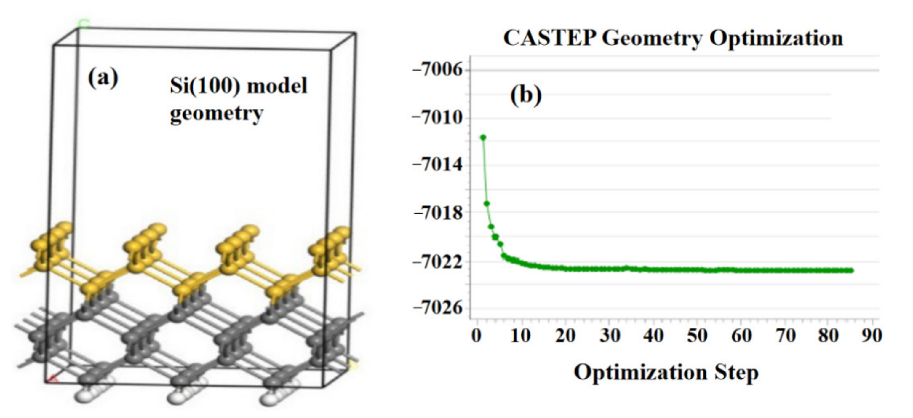
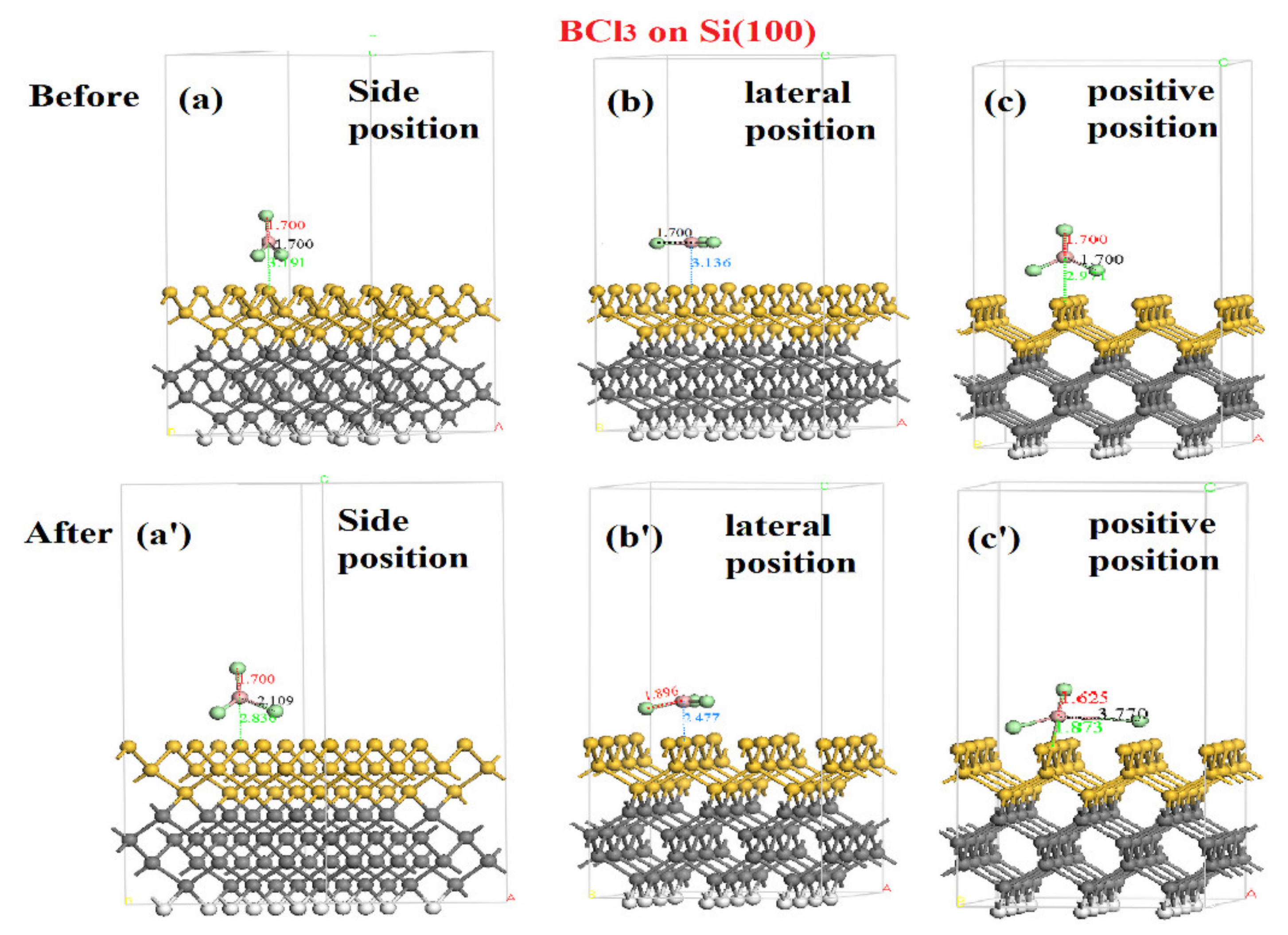
3.1. Adsorption of BCl3 on the Surface of Polysilicon Si(100)

The molecular structure of BCl3 is a plane regular triangle. The structure of BCl3 adsorbed on the Si(100) surface was obtained by placing BCl3 molecules on a super cell (3 × 3) surface and fully relaxing it. The surface optimization of BCl3 with different structures was performed as follows. A BCl3 molecule was used to establish stable adsorption models for three orientations: the side position, lateral position and positive position of the molecule. The changes in the distance before and after adsorption were compared and analyzed. The results are shown in Figure 2.
Changes in the distance between the molecules and the surface before and after the reaction for the three adsorption structures were observed. It was found that when BCl3 molecules are adsorbed on the Si(100) surface of the unit cell in the three possible structures, the distance before and after the adsorption has changed correspondingly, and the distance between the molecules and the surface of the unit cell in the three structural configurations is correspondingly shortened. This shows that an adsorption reaction between the BCl3 molecule and the Si(100) surface occurs readily. The distances of the ortho-adsorbed BCl3 molecule before and after optimization were markedly different, at 2.971 Å and 1.873 Å, respectively. The B atom in BCl3 forms a covalent bond with the Si(100) surface and one of the B–Cl bonds is elongated, indicating that the Si atom has an attractive effect on Cl. Table 1 shows the change in distance before and after adsorption in each of the three positions.
The adsorption energies of the three adsorption structures were then calculated. The smaller the adsorption energy, the easier it is to adsorb, and vice versa. The calculated results for the adsorption energy of the side, lateral and positive positions of the molecule are shown in Table 2.
According to the data in Table 2, the adsorption energies of the three adsorption modes on the Si(100) surface are all negative, indicating that BCl3 molecules are readily adsorbed by the Si(100) surface and that the adsorption reaction occurs easily on the surface. The relative adsorption energies of the three molecular orientations are as follows: E (lateral position) > E (side position) > E (positive position). It can be seen that the orientation in which BCl3 molecules are most easily adsorbed on the Si(100) surface is the positive position. Thus, the change in the molecular adsorption distance after adsorption was verified, and the most favorable orientation for adsorption was the positive position.
Differential electron density analysis (Figure 3a) and calculation of the charge distribution (Figure 3b) of BCl3 molecules adsorbed on the Si(100) surface were also carried out. The color of the Si atoms depicted at the bridge sites on the Si(100) surface is denser, indicating that a large amount of charge is transferred in this local area and that the charge has migrated after the adsorption reaction has occurred. The B–Cl bond on the right side is clearly elongated, and an electron cloud is formed between the Cl atom and the silicon atom at the adjacent bridge site on the right, indicating that the silicon atom at the adjacent bridge site on the right has an attractive effect on the Cl atom.

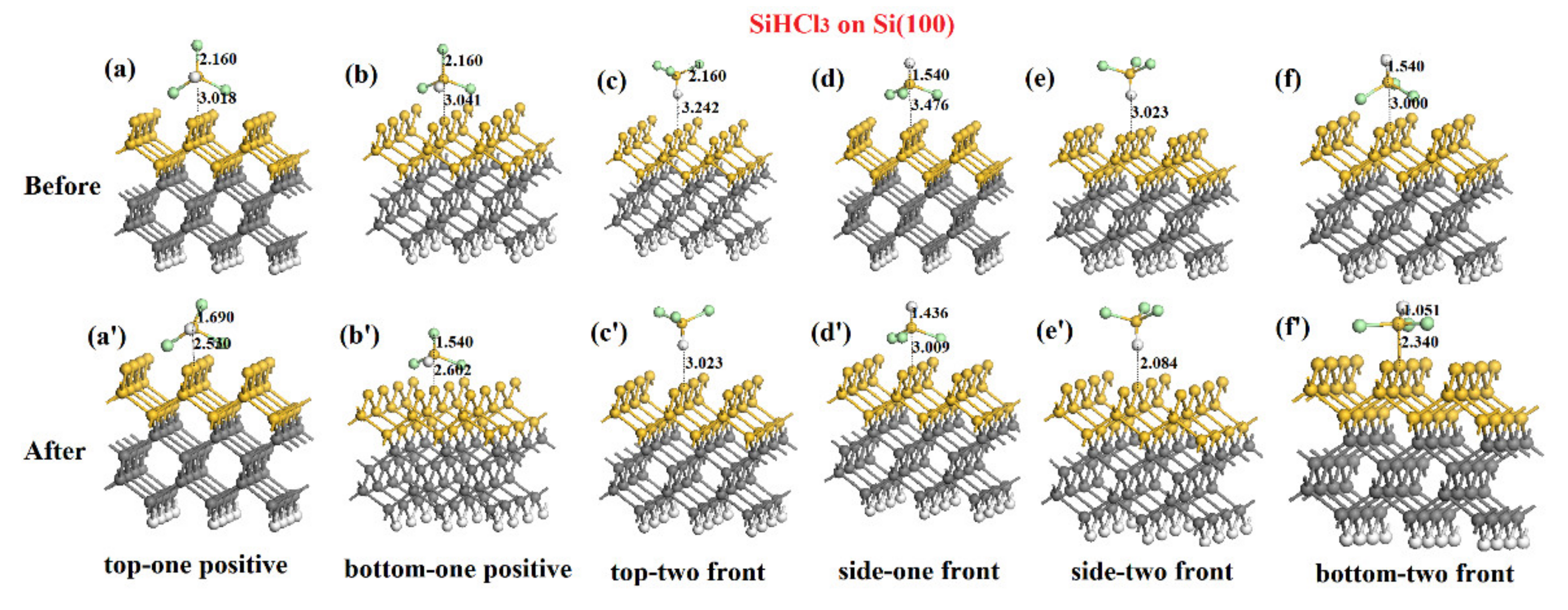
3.2. Adsorption of SiHCl3 Molecules on the Surface of Polysilicon Si(100)

The molecular structure of SiHCl3 is tetrahedral, and we discuss here the adsorption process of optimized SiHCl3 on the Si(100) surface. Figure 4 shows six possible adsorption positions on the surface, which can be described as the hydrogen top-one-positive position, hydrogen bottom-one-front position, hydrogen top-two-front position, hydrogen side-one-front position, hydrogen side-two-front position, and hydrogen bottom-two-front position. After the optimization calculation, the distance between the molecule and the surface was found to have been shortened, indicating that SiHCl3 is prone to react with the surface of the Si(100) unit cell. This conclusion can also be drawn from the changes in the distance before and after adsorption at the six adsorption sites listed in Table 3. When SiHCl3 is adsorbed at the second bottom-front position of the hydrogen, its distance changes from 3.000 Å to 2.340 Å. The Si atom of SiHCl3 forms a covalent bond with the Si atom at the bridging position, indicating that the SiHCl3 molecule has been adsorbed on the Si(100) unit cell. Simultaneously, it is observed that the Si–Cl bond of the SiHCl3 molecule is distinctly elongated, which indicates that the Cl atom is attracted by the Si atom adjacent to the bridge site.
Table 4 shows the calculated adsorption energy of SiHCl3 on the Si(100) surface. The adsorption energies obtained for the six adsorption structures are all negative, indicating that SiHCl3 reacts readily with the Si(100) surface. The order of the adsorption energies of the several positions is as follows: E(hydrogen side-two-front position) > E(hydrogen top-two-front position) > E(hydrogen top-one-positive position) > E(hydrogen bottom-one-front position) > E(hydrogen side-one-front position) > E(hydrogen bottom-two-front position). The adsorption energy (E) of SiHCl3 is greatest when the adsorption structure of the second hydrogen base is in the front position, indicating that adsorption is more likely to occur in this orientation, at the front position of the hydrogen base 2. From the calculated adsorption energies, it can be seen that the adsorption of SiHCl3 molecules in the hydrogen bottom-two-front position corresponds to the most favorable orientation, and the calculated adsorption distances confirm this conclusion.
To gain a deeper understanding of the charge distribution in the adsorption process of SiHCl3, we can use the electronic levels to characterize the reaction. The differential electron density and charge distribution of the SiHCl3 molecules adsorbed on the surface of the Si(100) unit cell from the face center downward were calculated. The calculated results are shown in Figure 5a,b. From the results shown in the figure, it can be seen that the color representing the charge concentrated in the bond between the Si atoms on the Si(100) surface and the Si atom in SiHCl3 is darker than that for other bonds. This not only shows that electrons have been transferred after adsorption, but also shows that a large amount of charge is transferred in this local area. Looking at the image of the adsorbed SiHCl3 molecule, it is seen that the three Cl atoms and the bonding angles between the H and Si atoms in the molecule have changed, and both the Cl and H atoms show an upward posture. In addition, it can be seen that the silicon atoms on the surface and the two Si atoms at the right and back of the bridge silicon atoms adjacent to the bonded Si atoms and the corresponding Cl atoms form an electron cloud. This proves that the two have an attractive effect.

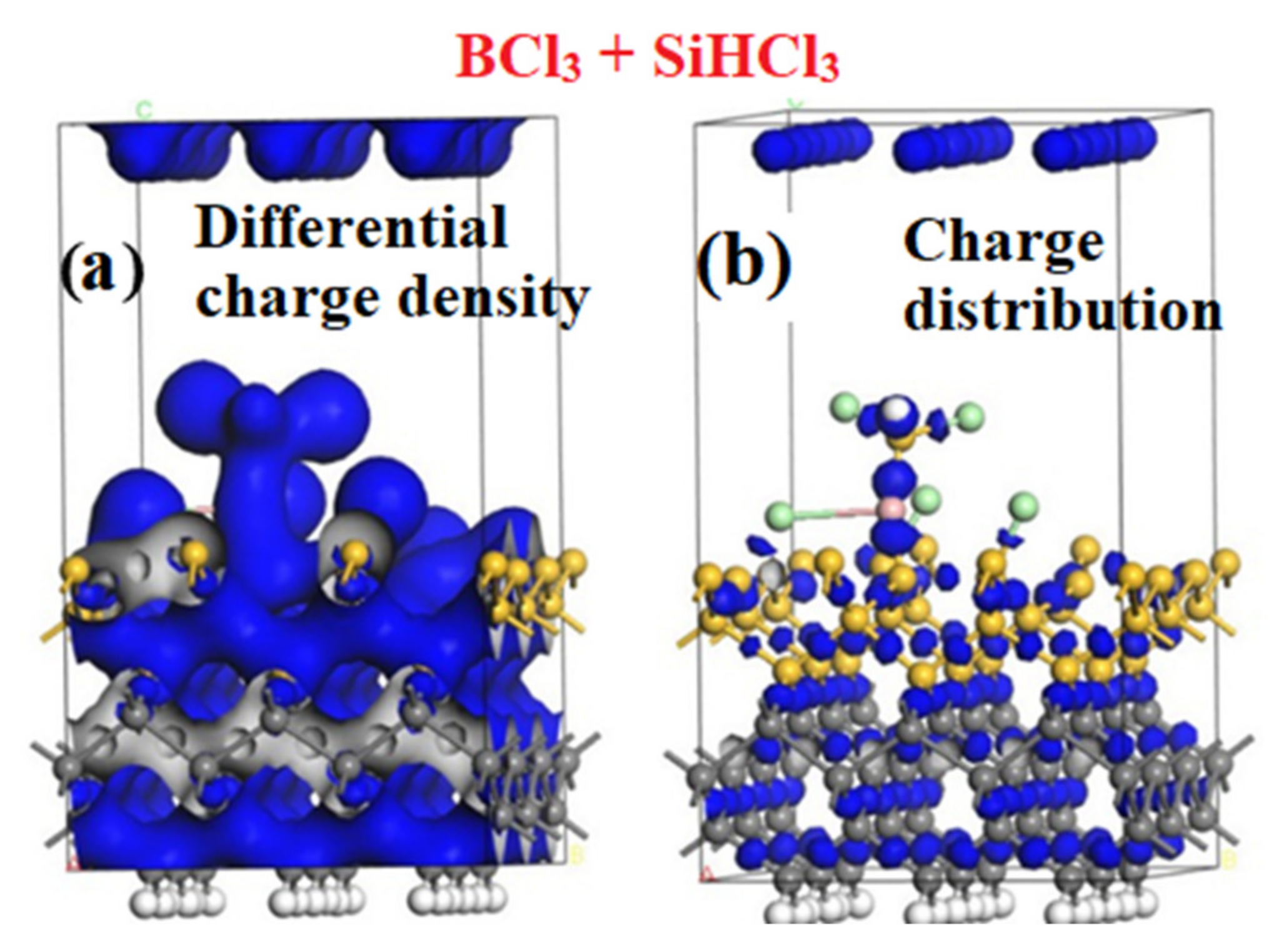
3.3. Co-Adsorption of BCl3 and SiHCl3 on the Surface of Polysilicon Si(100)

A BCl3 molecule and a SiHCl3 molecule were placed together on the surface of the Si(100) supercell to investigate the adsorption reaction. Figure 6 shows the structural changes before and after the co-adsorption of BCl3 and SiHCl3 on the Si(100) surface. Compared to the structure before adsorption in Figure 6a, it can be concluded from the structure after adsorption (Figure 6b) that the Si atom in the SiHCl3 molecule forms a covalent bond with the B atom in BCl3. A Cl atom in each of the BCl3 and SiHCl3 molecules undergoes a dissociation reaction and is adsorbed on the Si atom at the nearest bridge site on the Si(100) surface. The bond lengths of the other Cl–B bonds in the BCl3 molecule are significantly elongated, and the B atom is adsorbed on the Si(100) surface at the same time. These results indicate that BCl3 and SiHCl3 molecules are placed on the Si(100) surface simultaneously. After the adsorption reaction, it is evident that BCl3 is more easily adsorbed on the Si(100) surface than is SiHCl3. When BCl3 and SiHCl3 coexist on the Si(100) surface, they are more likely to have an effect than SiHCl3 alone on the surface. Moreover, their simultaneous presence there will be accompanied by a dissociation process; in which each dissociates a Cl atom, and the Cl atom in the BCl3 molecule is attracted by the Si(100) surface.
A microscopic electronic analysis was also performed of the charge distribution and differential electron density when BCl3 and SiHCl3 are present together on the surface of polysilicon. The darker blue color between BCl3 and SiHCl3 in Figure 7b indicates that there is a large amount of electron transfer, and it can be seen that the B–Cl bond in the BCl3 molecule is distinctly elongated, and a dissociated Cl atom is adsorbed on the Si(100) surface, indicating that it charge transfer has occurred during the adsorption process. From the charge density results in Figure 7a, indicating charge transfer between the surface and the molecules, we can also see where the electrons accumulate, which proves the occurrence of the adsorption reaction.

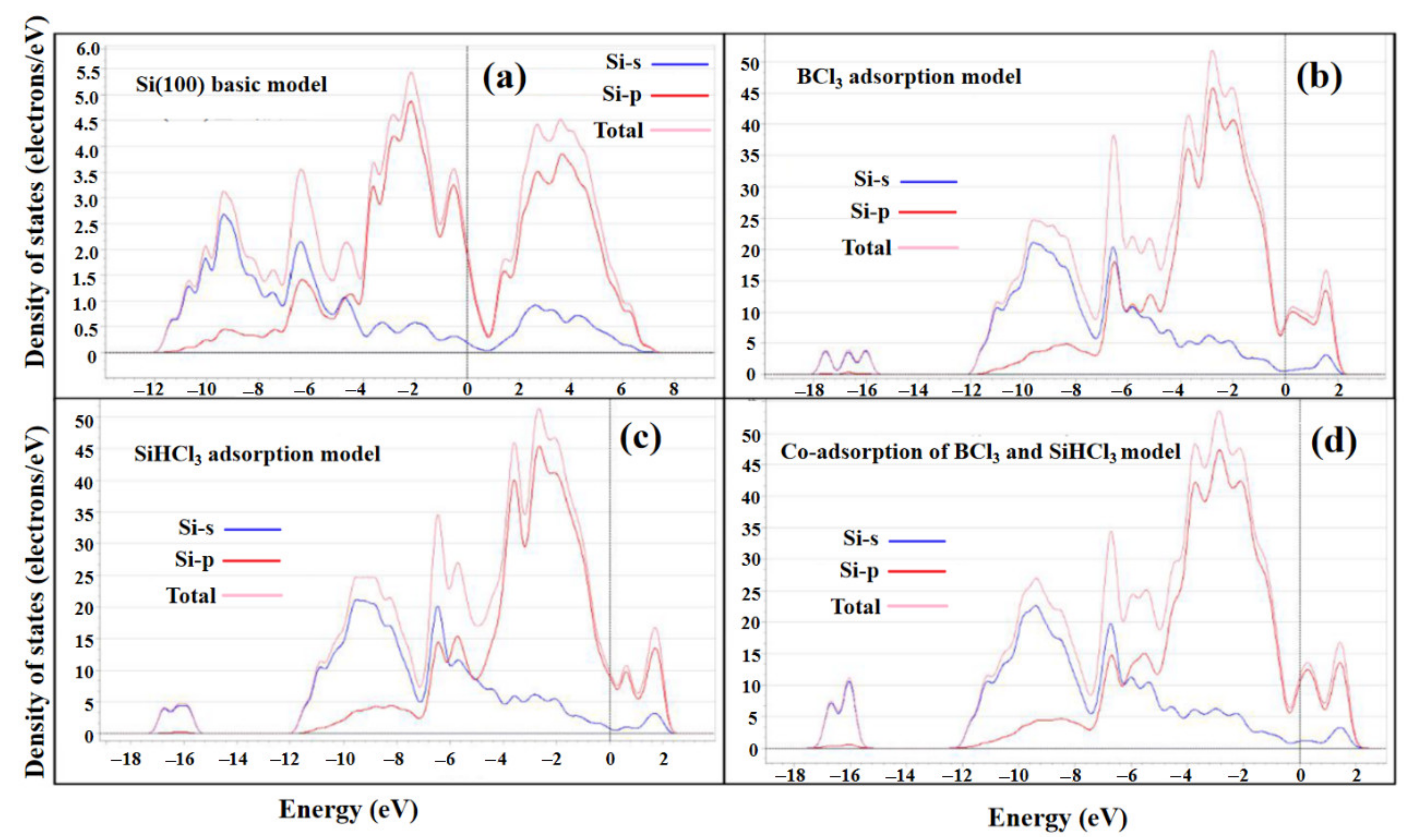
3.4. Electronic Structure Analysis

To further understand the bonding mechanism of the adsorption of BCl3 and SiHCl3 on the Si(100) surface, the adsorption density of states, partial density of states, and Mulliken charge distribution were calculated, and the results are shown in Figure 8 and Table 5. It can be observed that the Si3s orbital lies far away in energy from the Fermi level on the surface of the Si(100) unit cell. After the adsorption reaction, the electrons of the Si3s orbital are not easily transferred. The valence band where electron transfer occurs is Si3p, which constitutes the valence band on the left side of the Fermi level on the surface of the Si(100) unit cell. Although it is theoretically impossible for the Si3s orbital to transfer electrons, a very small amount of electron transfer does occur from the Si3s orbital after the reaction. The valence state on the right side of the Fermi level is composed of Si3d orbitals, and the bandgap between the top of the valence band and the bottom of the conduction band is 1.502 eV. After the reaction, the bandgap is reduced to 0.087 eV. The narrowing of the bandgap indicates that the Si is more likely to react, and its chemical properties become more active, which in turn indicates that it is more likely to interact with BCl3 and SiHCl3 molecules.
By analyzing the electronic density of states of BCl3 and SiHCl3 molecules adsorbed on the surface of the Si(100) unit cell in Figure 8, it is found that after the two molecules are adsorbed on the surface of the unit cell, their band gaps are narrowed and the electrons inside the molecules are transferred to the outermost electron layer and to the conduction band, which is more reactive. Based on molecular chemical structure theory, we know that the B atom in the BCl3 molecule has three coordination sites, and the electron configuration of B is 1s22s22p1, showing that B is an electron deficient atom. Six electrons are provided by three Cl atoms, and each of the three Cl atoms also provides a filled 2p orbital that is side-by-side with an empty p orbital of the B atom and is thus able to form a strong π bond. The formation of bonds by sp2 hybridization can explain the three B–Cl bonds in BCl3. Similarly, for the SiHCl3 molecule, electrons are transferred to the outermost electron layer. The Si atom in the SiHCl3 molecule has four coordination sites and the outermost electron configuration is 3s23p2, which is eventually completed by the four covalent bonds formed with Si. This can explain the origin of the four covalent bonds, and it can be concluded that the spatial configuration of SiHCl3 is a that of a regular tetrahedron.
From the Mulliken charge distribution of the two molecules shown in Table 5, it can be observed that when SiHCl3 is adsorbed on the surface of the Si(100) unit cell, charge transfer occurs, and there are two charge transfer paths. The first is the transfer of 1.30 eV of charge from the Si atom of the SiHCl3 molecule to the surface of the unit cell. The second is charge transfer from the surface of the unit cell to the three Cl atoms and the H atom of the SiHCl3 molecule, a charge transfer of 1.06 eV. After fitting and offsetting, it is found that during the entire adsorption reaction of SiHCl3 on the surface of the Si(100) unit cell, the Si atom in the SiHCl3 has transferred a net 0.24 eV of charge to the surface of the Si(100) unit cell. When BCl3 is adsorbed on the surface of the Si(100) unit cell, significant charge transfer also occurs, and there are two charge transfer paths. The first is a transfer of 1.52 eV from the B atom in BCl3 to the surface of the unit cell. The second is a transfer of 1.23 eV from the surface of the unit cell to the three Cl atoms and one H atom in the BCl3 molecule. After fitting and offsetting, during the entire adsorption reaction of BCl3 on the surface of the Si(100) unit cell, the B atom in BCl3 is seen to have transferred 0.29 eV of charge to the surface of the Si(100) unit cell.
According to the results for transfer of electrons between SiHCl3, BCl3, and the surface of polysilicon during the adsorption process, both molecules transfer charge to the surface of the unit cell during adsorption, with BCl3 transferring 0.05 eV more charge to the surface of the Si(100) unit cell than SiHCl3 does. It can be shown that the surface of the Si(100) unit cell has a definite adsorption effect on BCl3 and SiHCl3 molecules, and that the B atoms in BCl3 are more easily adsorbed on the Si(100) surface, which means that B and polysilicon will be deposited on the silicon rod together during the production process. The above results also explain the phenomenon that when BCl3 and SiHCl3 molecules are co-adsorbed on the surface of the Si(100) unit cell, the Si atoms in the SiHCl3 molecules first form a covalent bond with the B atoms in BCl3.
The B impurities may deposit on the surface of the silicon rod competing with polysilicon and the trace B-compound impurities may be enriched by the influence of transport phenomena. The above two phenomena are the main reasons causing the high-impurity B in the silicon production. It is obvious that the adsorption of BCl3 on silicon to cause the deposition of B on silicon surface. Therefore, transport phenomenon investigation may be effective method to reduce boron impurity inside poly-silicon, such as increasing mole fraction of H2 and temperature.

4. Conclusions

(1)
BCl3 and SiHCl3 are mainly adsorbed on the surface of the Si(100) unit cell in the positive position and the hydrogen bottom-two-front position of the molecule, respectively. The discrete distances of BCl3 and SiHCl3 from the surface of the Si(100) unit cell are 1.873 Å and 2.340 Å, respectively, and the separation energies are −35.2549 kcal/mol and −10.64 kcal/mol, respectively.
(2)
Compared with SiHCl3, BCl3 reacts more easily with the Si(100) surface, and when BCl3 and SiHCl3 coexist, BCl3 reacts more readily than SiHCl3 with the Si(100) surface. When BCl3 and SiHCl3 are present simultaneously, the gas phase reaction is accompanied by a dissociation process, in which each molecule dissociates a Cl atom that is adsorbed on the Si(100) surface. At the same time, a distinctly elongated B–Cl bond shows that the Si(100) surface also has an attractive effect on Cl atoms.
(3)
After the adsorption of SiHCl3 and BCl3, 0.24 and 0.29 eV of charge, respectively, are found to have been transferred from the molecule to the surface of the unit cell. Both BCl3 and SiHCl3 are readily adsorbed on the surface of the Si(100) unit cell, but BCl3 is more easily adsorbed. These results confirm that the B atom in BCl3 in the adsorption model forms a covalent bond with the Si atom on the Si(100) unit cell surface, and the Si atom in the SiHCl3 molecule forms a covalent bond with the B atom in BCl3.

Author Contributions

Conceptualization, L.H. and Y.H.; Data curation, F.C., Y.H. and N.Y.; Investigation, J.W., Y.H. and N.Y.; Methodology, N.Y. and G.X.; Software, L.T. and L.H.; Validation, Q.Y.; Writing—Original draft, Q.Y.; Writing—Review and editing, Q.Y., J.W. and Y.H. All authors have read and agreed to the published version of the manuscript.

Funding

This research was funded by the National Natural Science Foundation of China Project (No. 21566015 and No. 52074141).

Institutional Review Board Statement

Not applicable.

Informed Consent Statement

Informed consent was obtained from all subjects involved in the study.

Data Availability Statement

Data sharing not applicable. No new data were created or analyzed in this study. Data sharing is not applicable to this article.

Conflicts of Interest

The authors declare no conflict of interest.

References

  1. Chen, J.; Zhang, X. Prediction of thermal conductivity and phonon spectral of silicon material with pores for semiconductor device. Phys. B Condens. Matter 2021, 614, 413034. [Google Scholar] [CrossRef]
  2. Chen, P.; Zeng, Q.; Guo, W.; Chen, J. The source, enrichment and precipitation of ore-forming elements for porphyry Mo deposit: Evidences from melt inclusions, biotite and fluorite in Dasuji deposit, China. Ore Geol. Rev. 2021, 135, 104205. [Google Scholar] [CrossRef]
  3. Cheng, D.; Gao, Y.; Liu, R. Finite element analysis on processing stress of polysilicon cut by diamond multi-wire saw. Mater. Sci. Semicond. Process. 2021, 131, 105860. [Google Scholar] [CrossRef]
  4. Xiong, Q.M.; Chen, Z.; Huang, J.-T.; Zhang, M.; Song, H.; Hou, X.F.; Li, X.B.; Feng, Z.J. Preparation, structure and mechanical properties of Sialon ceramics by transition metal-catalyzed nitriding reaction. Rare Met. 2020, 39, 589–596. [Google Scholar] [CrossRef]
  5. Zhou, L.; Li, S.; Tang, Q.; Deng, X.; Wei, K.; Ma, W. Effects of solidification rate on the leaching behavior of metallic impurities in metallurgical grade silicon. J. Alloys Compd. 2021, 882, 160570. [Google Scholar] [CrossRef]
  6. Gao, M.; Liu, B.; Zhang, X.; Zhang, Y.; Li, X.; Han, G. Ultrathin MoS2 nanosheets anchored on carbon nanofibers as free-standing flexible anode with stable lithium storage performance. J. Alloys Compd. 2022, 894, 162550. [Google Scholar] [CrossRef]
  7. O’Mara, W.; Herring, R.B.; Hunt, L.P. Handbook of Semiconductor Silicon Technology; Crest Publishing House: Kettering, UK, 2007. [Google Scholar]
  8. Davis, K.O.; Brooker, R.P.; Seigneur, H.P.; Rodgers, M.; Rudack, A.C.; Schoenfeld, W.V. Pareto analysis of critical challenges for emerging manufacturing technologies in silicon photovoltaics. Sol. Energy 2014, 107, 681–691. [Google Scholar] [CrossRef] [Green Version]
  9. Chanlaor, P.; Limtrakul, S.; Vatanatham, T.; Ramachandran, P.A. Modeling of Chemical Vapor Deposition of Silane for Silicon Production in a Spouted Bed via Discrete Element Method Coupled with Eulerian Model. Ind. Eng. Chem. Res. 2018, 57, 12096–12112. [Google Scholar] [CrossRef]
  10. Filtvedt, W.O.; Holt, A.; Ramachandran, P.A.; Melaaen, M.C. Chemical vapor deposition of silicon from silane: Review of growth mechanisms and modeling/scaleup of fluidized bed reactors. Sol. Energy Mater. Sol. Cells 2012, 107, 188–200. [Google Scholar] [CrossRef]
  11. Shi, S.; Guo, X.; An, G.; Jiang, D.; Qin, S.; Meng, J.; Li, P.; Tan, Y.; Noor ul Huda Khan Asghar, H.M. Separation of boron from silicon by steam-added electron beam melting. Sep. Purif. Technol. 2019, 215, 242–248. [Google Scholar] [CrossRef]
  12. Wang, C.; Wang, T.; Li, P.; Wang, Z. Recycling of SiCl4 in the manufacture of granular polysilicon in a fluidized bed reactor. Chem. Eng. J. 2013, 220, 81–88. [Google Scholar] [CrossRef]
  13. Safarian, J. Thermochemical Aspects of Boron and Phosphorus Distribution Between Silicon and BaO-SiO2 and CaO-BaO-SiO2 lags. Silicon 2019, 11, 437–451. [Google Scholar] [CrossRef] [Green Version]
  14. Bye, G.; Ceccaroli, B. Solar grade silicon: Technology status and industrial trends. Sol. Energy Mater. Sol. Cells 2014, 130, 634–646. [Google Scholar] [CrossRef]
  15. Bullón, J.; Margaria, T.; Miranda, A.; Mıguez, J. Physical and chemical analysis of the upgraded metallurgical silicon for the solar industry. In Silicon Form the Chemical and Solar Industry IX; Norwegian University of Science and Technology: Oslo, Norway, 2008. [Google Scholar]
  16. Haupfear, E.A.; Schmidt, L.D. Kinetics of boron deposition from BBR3 + H2. Chem. Eng. Sci. 1994, 49, 2467–2481. [Google Scholar] [CrossRef]
  17. Liu, W.; Huang, F.; Liao, Y.; Zhang, J.; Ren, G.; Zhuang, Z.; Zhen, J.; Lin, Z.; Wang, C. Treatment of CrVI-Containing Mg(OH)2 Nanowaste. Angew. Chem. 2008, 120, 5701–5704. [Google Scholar] [CrossRef]
  18. Jenkinson, J.P.; Pollard, R. Thermal diffusion effects in chemical vapor deposition reactors. J. Electrochem. Soc. 1984, 131, 2911. [Google Scholar] [CrossRef]
  19. Sezgi, N.A.; Ersoy, A.; Dogu, T.; Özbelge, H.Ö. CVD of boron and dichloroborane formation in a hot-wire fiber growth reactor. Chem. Eng. Process. Process Intensif. 2001, 40, 525–530. [Google Scholar] [CrossRef]
  20. Asli Sezgi, N.; Dogu, T.; Onder Ozbelge, H. Mechanism of CVD of boron by hydrogen reduction of BCl3 in a dual impinging-jet reactor. Chem. Eng. Sci. 1999, 54, 3297–3304. [Google Scholar] [CrossRef]
  21. Liu, Y.; Zhang, L.; Cheng, L.; Zeng, Q.; Zhang, W.; Yang, W.; Feng, Z.; Li, S.; Zeng, B. Uniform design and regression analysis of LPCVD boron carbide from BCl3–CH4–H2 system. Appl. Surf. Sci. 2009, 255, 5729–5735. [Google Scholar] [CrossRef]
  22. Deng, J.; Cheng, L.; Zheng, G.; Su, K.; Zhang, L. Thermodynamic study on co-deposition of ZrB2–SiC from ZrCl4–BCl3–CH3SiCl3–H2–Ar system. Thin Solid Film. 2012, 520, 7030–7034. [Google Scholar] [CrossRef]
  23. Mahammedi, N.A.; Ferhat, M.; Belkada, R. Prediction of indirect to direct band gap transition under tensile biaxial strain in type-I guest-free silicon clathrate Si46: A first-principles approach. Superlattices Microstruct. 2016, 100, 296–305. [Google Scholar] [CrossRef]
  24. Delley, B. An all-electron numerical method for solving the local density functional for polyatomic molecules. J. Chem. Phys. 1990, 92, 508–517. [Google Scholar] [CrossRef]
  25. Clark, S.J.; Segall, M.D.; Pickard, C.J.; Hasnip, P.J.; Probert, M.I.; Refson, K.; Payne, M.C. First principles methods using CASTEP. Z. Für Krist. Cryst. Mater. 2005, 220, 567–570. [Google Scholar] [CrossRef] [Green Version]
  26. Zhang, Y.F.; Viñes, F.; Xu, Y.J.; Li, Y.; Li, J.Q.; Illas, F. Role of Kinetics in the Selective Surface Oxidations of Transition Metal Carbides. J. Phys. Chem. B 2006, 110, 15454–15458. [Google Scholar] [CrossRef] [PubMed]
  27. Vanderbilt, D. Soft self-consistent pseudopotentials in a generalized eigenvalue formalism. Phys. Rev. B 1990, 41, 7892. [Google Scholar] [CrossRef] [PubMed]
  28. Wang, Z.; Chen, X.; Cheng, Y.; Niu, C. Adsorption and Deposition of Li2O2 on the Pristine and Oxidized TiC Surface by First-principles Calculation. J. Phys. Chem. C 2015, 119, 25684–25695. [Google Scholar] [CrossRef]
  29. Sun, W.; Ceder, G. Efficient creation and convergence of surface slabs. Surf. Sci. 2013, 617, 53–59. [Google Scholar] [CrossRef]
  30. Peng, M.; Shi, B.; Han, Y.; Li, W.; Zhang, J. Crystal facet dependence of SiHCl3 reduction to Si mechanism on silicon rod. Appl. Surf. Sci. 2022, 580, 152366. [Google Scholar] [CrossRef]
  31. Galán, O.A.L.; Carbajal-Franco, G. Energy profiles by DFT methods for CO and NO catalytic adsorption over ZnO surfaces. Catal. Today 2021, 360, 38–45. [Google Scholar] [CrossRef]
Figure 1. Model geometry and optimization curve of Si(100) surface. (a) is the Si(100) model geometry; (b) is the model optimization convergence curve.
Minerals 12 00651 g001
Figure 2. Diagrams of the molecular structure and distance of BCl3 before and after adsorption on the Si(100) surface. Diagrams (ac) show the adsorption structure before reaction, (a’c’) the adsorption structure after the reaction, ((a,a’) show side position of the molecule, (b,b’), lateral position of the molecule, and (c,c’) positive position of the molecule).
Minerals 12 00651 g002
Figure 3. Differential charge density (a) and charge distribution (b) of BCl3 adsorbed on the Si(100) surface of the unit cell.
Minerals 12 00651 g003
Figure 4. Diagram of molecular structures and distances of SiHCl3 before and after adsorption on the Si(100) surface. Diagrams (af) show the adsorption structures before reaction, (a’f’) those after reaction ((af,a’f’) show hydrogen in the top-one-positive, bottom-one-front, top-two-front, side-one-front, side-two-front, and bottom-two-front positions, respectively).
Minerals 12 00651 g004
Figure 5. Differential charge density (a) and charge distribution (b) after SiHCl3 is adsorbed on the Si(100) surface.
Minerals 12 00651 g005
Figure 6. Structure changes before (a) and after (b) the co-adsorption of BCl3 and SiHCl3.
Minerals 12 00651 g006
Figure 7. Differential charge density (a) and charge distribution (b) before and after the co-adsorption of BCl3 and SiHCl3 on the surface.
Minerals 12 00651 g007
Figure 8. State density changes of BCl3 and SiHCl3 molecules after the adsorption on the Si(100) cell surface. (a) is the density of states of Si(100); (b) is the density of states for the BCl3 adsorption model; (c) is the density of states for the SiHCl3 adsorption model; (d) is the density of states for the co-adsorption of BCl3 and SiHCl3.
Minerals 12 00651 g008
Table 1. Distances before and after the adsorption of BCl3 on the Si(100) surface.
Adsorption ModeDistance before Optimization (Å)Optimized Distance (Å)
Side position of the molecule3.1912.836
Lateral position of the molecule3.1392.447
Positive position of the molecule2.9171.873
Table 2. Adsorption energy of BCl3 after adsorption on Si(100) surface.
Adsorption ModeEadsorption (kcal/mol)
Side position of the molecule−29.2613
Lateral position of the molecule−23.5846
Positive position of the molecule−35.3549
Table 3. Distances before and after the adsorption of SiHCl3 on the Si(100) surface.
Adsorption ModeDistance before Optimization (Å)Optimized Distance (Å)
Hydrogen top-one-positive position3.0182.530
Hydrogen bottom-one-front position3.0412.602
Hydrogen top-two-front position3.2423.023
Hydrogen side-one-front position3.4763.009
Hydrogen side-two-front position3.0232.804
Hydrogen bottom-two-front position3.0002.340
Table 4. Adsorption energy of SiHCl3 after adsorption on the Si(100) surface.
Adsorption ModeEadsorption (kcal/mol)
Hydrogen top-one-positive position−4.02
Hydrogen bottom-one-front position−6.07
Hydrogen top-two-front position−3.41
Hydrogen side-one-front position−8.92
Hydrogen side-two-front position−2.47
Hydrogen bottom-two-front position−10.64
Table 5. Mulliken charge co-adsorption of BCl3 and SiHCl3 molecules on the surface of Si(100) unit cell.
ProjectSpeciesSpdTotalCharge
(eV)
Change
(eV)
Ideal BCl3B06.262.4410.871.130
Cl11.965.3307.28−0.28
Cl21.965.3307.28−0.28
Cl31.965.3207.28−0.28
Ideal SiHCl3Si3.187.423.3613.961.130
Cl12.086.1208.20−0.32
Cl22.086.1208.20−0.33
Cl32.086.1208.20−0.35
H1.764.2806.04−0.30
Si(100) surface adsorption BCl3B06.232.1710.681.320.29
Cl11.955.3607.34−0.31
Cl21.955.3207.27−0.27
Cl31.955.3307.28−0.28
Si(100) surface adsorption SiHCl3Si2.216.142.1310.481.020.24
Cl11.955.3907.34−0.34
Cl21.955.3907.24−0.34
Cl31.955.3307.29−0.29
H1.955.3607.34−0.31
Publisher’s Note: MDPI stays neutral with regard to jurisdictional claims in published maps and institutional affiliations.

