
Evolution Characteristics of Overlying Strata Fractures in Paste Composite Filling Stope

1
School of Energy Engineering, Xi’an University of Science and Technology, Xi’an 710054, China
2
Henan Key Laboratory for Green and Efficient Mining & Comprehensive Utilization of Mineral Resources, Henan Polytechnic University, Jiaozuo 454000, China
3
Shaanxi Province Key Laboratory of Coal Mine Water Disaster Prevention and Control Technology, Xi’an 710077, China
4
Huaneng Equipment Manufacturing Co., Ltd., Shandong Mining Machinery, Weifang 261000, China
5
Shaanxi Xiaobaodang Mining Co., Ltd., Yulin 719300, China
*
Author to whom correspondence should be addressed.
Minerals 2022, 12(5), 654; https://0-doi-org.brum.beds.ac.uk/10.3390/min12050654
Submission received: 17 April 2022
/
Revised: 16 May 2022
/
Accepted: 19 May 2022
/
Published: 22 May 2022
(This article belongs to the Special Issue Backfilling Materials for Underground Mining, Volume III)
Abstract
:Paste composite filling mining (PCFM) is one of the effective ways to achieve water-preserved mining (preservation of the waterproof strata). To investigate the laws of fracture propagation of the overlying strata in the PCFM stope, a kinematic model of overlying strata in the PCFM was established, which identified the major determinants to the development of overlying strata fractures. Taking the 112,201 working face of the test mine as the research background, the physical similar simulation, numerical computation, and theoretical analysis were combined to analyze the development characteristics of overlying strata fractures in the PCFM under the reaction between many factors (mining height, filling ratio, burial depth). The results show that the larger the mining height of the working face, the larger the development degree of overlying strata fractures. When the mining height is smaller, fractures are mostly distributed on both sides of the coal wall; when the mining height is larger, overlying strata fractures are mostly distributed on both sides of the coal wall and the upper part of overlying strata. The larger the paste filling ratio of the working face, the smaller the development degree of overlying strata fractures. Overlying strata fractures are mostly distributed in overlying strata on both sides of the coal wall. When the filling ratio of the working face increases, it is possible to effectively control the development of overlying strata fractures. The shallower the burial depth of the working face is, the faster the fractures are developed. With the increase of the burial depth, the development of overlying strata fractures is reduced, and overlying strata fractures will finally tend to be a stable value. The research results provide an important theoretical foundation for the application of the localized paste filling mining technique in the water-preserved mining, and also complement the theories of filling mining.
1. Introduction
The edge of the Maowusu Desert in western China holds abundant coal reserves and the precious water-bearing strata (water-bearing strata in Salawusu Formation of coal series in Yushenfu Area Shaanxi Province) are severely polluted and lost by underground coal mining, resulting in increasing conflicts between coal mining and environment protection [1,2,3,4]. Over recent years, paste filling technique has been widely applied for all mines, which can not only effectively control the stability of overlying strata and reduce the development degree of fracture zone, but also migrate strata behaviors and improve the stability of the “support-surrounding rock” system. It is one of the effective ways to thoroughly solve water-preserved mining problems [5,6,7,8,9].
Scholars at home and abroad have conducted much research on the stability of overburden in filling mining and the properties of filling materials. A wide range of research works have reported the stability of overlying strata in the filling mining by domestic scholars. Xu J.L. et al. [10] analyzed the fundamental theories of filling mining for coal mine structures and the stability of the composite load bearing structure for the filling mine of column structures, and applied them in the field, achieving the purposes of partial filling mining and providing an important guarantee for green and efficient mining. To solve strata movement and deformation, as well as surface subsidence related problems in gangue filling mining, Zhang P.F. et al. [11] provided an analysis of movement and deformation of roof strata and characteristics of overlying strata fracture distribution in filling mining by using the combined method of physical simulation and numerical computation. Chen S.J. et al. [12] taking the 2351 working face of paste filling mining in Daizhuang Coal Mine as an example, studied the spatio-temporal structure model and movement laws of overlying strata in the paste filling mining of strip coal pillar. Guo G.L. et al. [13] investigated the laws of strata movement for depth solid filling mining. The results indicate that filling mining can effectively control the failure of its overlying strata and propose that improving the filling rate of coal wastes and initial density can effectively improve the movement control effects of filling strata. Li J. [14] built the mechanical calculation model of laminated composite beams on elastic foundations of overlying strata in the coal waste filling mining, and represented the compactness characteristics of solid filling materials by the coefficients of elastic foundations to deduce the bending moment and deflection equations of overlying strata and identify the critical conditions of bedrock failure, obtaining the number of strata and height of overlying strata failure under different filling rate conditions. Yang G. et al. [15] applied FLAC3D software to study the roles of filling mining in inhibiting the failure of overlying strata and reducing the surface subsidence. Lv W.Y. et al. [16] built the mechanical model of overlying strata movement and deformation in the local filling stope of steeply dipping coal seam and investigated the laws of overlying strata migration. Helinski M. et al. [17] applied the numerical method to build the cement characteristic model for sensitivity study, which revealed the complicated interaction mechanisms between all properties and analyzed the laws of strata behaviors. Russian scholars [18,19] studied the impact of a large amount of waste gangue produced in the mining process on the environment and human activities, and examined the cost and quality of these waste gangue as new backfilling materials. Poland scholars [20,21] investigated and studied various backfilling methods used by modern mining enterprises, and studied the influence of particle size, water content, and adhesion of waste gangue on backfilling quality through experiments. The development system applied in mineral extraction was analyzed, and a method of selecting deposit development technology and reasonable filling mixture composition under given filling parameters was proposed. Saudi Arabian scholars [22,23] studied the effects of cement and air-entraining doses on the strength, fresh density, and dry density of mine backfilling materials through a uniaxial compressive strength test. The research results showed that the air-entraining admixture can effectively improve the strength of the backfilling material and improve its filling fluidity. The experiment of other mine filling materials replacing cement in paste was studied, and the influence of different content on the strength of paste filling materials was analyzed. Canadian scholars [24,25] studied the effect of polycarboxylate ether-based superplasticizer (PES), time, and temperature on the strength of paste filling materials through experiments. The results showed that adding the PES can significantly improve the strength of paste filling materials and affect the microstructure and hydraulic properties of paste filling materials, and the yield stress and viscosity of cemented paste backfill (CPB) increased with the increase of time and temperature. Turkey scholars [26,27] studied the effect of the content of fine ground construction and demolition waste (CDW) on the filling material of sulfide tailings paste through experiments, and the influence of fine ground CDW as filling material on groundwater pollution is studied. The results showed that the strength of CPB increased with the increase of fine ground CDW.
As understanding the occurrence and propagation of cracks in the overlying strata is fundamental to preserving the water-protective stratum, the associated study appears very important for water-preserved mining. Remarkable research results have been achieved in the movement and migration of overlying strata in the complete filling mining, roadway filling mining, and strip filling mining. However, no deep research has been made on the development of overlying strata fractures in the paste fillings-caving roof composite filling mining, nor have its mechanisms been known. In this regard, the purpose of this work was to investigate the laws of fracture propagation of the overlying strata in the paste composite filling mining (PCFM) stope. To achieve the goal, it is necessary to solve the following tasks: (1) overlying strata stability criterion, (2) main influencing factors of overlying strata fracture development, and (3) development law of overlying strata fractures. In this paper, taking the 112,201 working face of test mine as the research background, the physical similar simulation, numerical computation, and theoretical analysis were applied to investigate the development characteristics and evolution laws of overlying strata fractures under the reaction between many factors (mining height, filling ratio, burial depth), based on the analysis of determinants to the evolution of overlying strata fractures in the PCFM stope. This study provides an important theoretical basis for determining the occurrence conditions of mine water inrush, predicting water inrush, and formulating mine water hazard prevention and control measures.
2. Methods
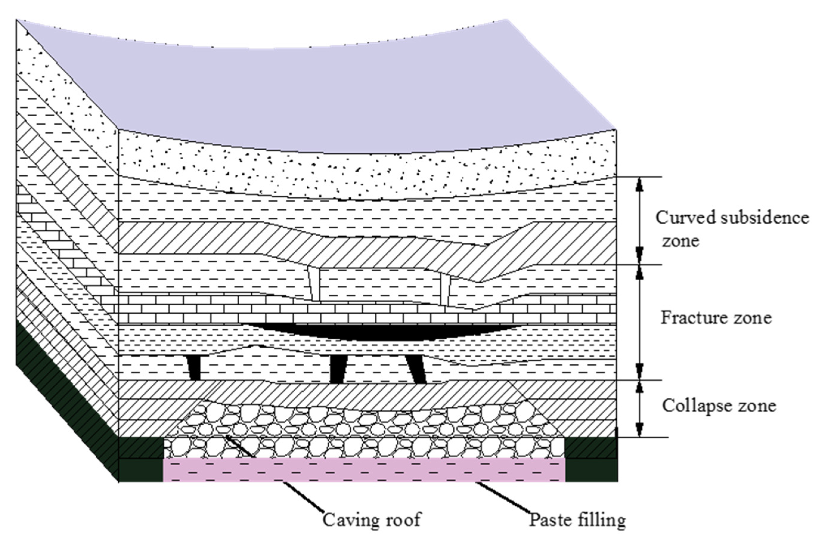
PCFM is to support the overlying strata by the composite filling body that is formed by paste filling body and caving roof and combined with the bulking force of loose rocks. The traditional mine paste filling technology is a process of processing coal gangue, construction waste, fly ash, cement, and a small amount of additives, then mixing them with water according to a certain proportion, and making filling slurry on the ground and transporting it to the underground goaf through ground grouting system and transportation pipeline. The layout of the working face of PCFM is the same as that of conventional paste filling mining. The laying and filling pipeline moves with the movement of the support. The support adopts the filling hydraulic support and drags the filling formwork under the tail beam of the support. The filling formwork and the overlying caving roof would achieve composite filling mining, as shown in Figure 1. Compared with other filling methods, this method can also effectively reduce filling costs, simplify the filling process, reduce the dosage of filling materials, improve the filling speed, and minimize the impacts on the production [28,29].
2.1. Engineering Background
The test mine is approximately 15.5 km in length from south to north and about 14.5 km in width from east to west. The well field covers an area of 219.8 km2. The mine well is divided into 2 levels. The average burial depth of 112,201 working face is 277.75~387.99 m, and the elevation of coal floor is 920~980 m. The thickness of coal seam is 3.58~8.06 m, and the average thickness is 6 m, with the thick coal seam prevailing. The length of the working face is 300 m, and the maximum and minimum dip angles of the coal seam are 3° and 1°, respectively, with an average dip angle of 2°. The coal seam contains 1 layer of dirt band with a thickness of 0.10~0.56 m. The main lithologies of the roof are siltstone and fine sandstone, followed by medium sandstone; the same of the floor is siltstone, followed by fine sandstone and sandy mudstone, locally distributed with medium sandstone. According to the results of rock mechanical experiment made in the laboratory, physical and mechanical parameters of coal seams and main strata were obtained, as shown in Table 1.
The filling paste material is mainly composed of coal gangue, fly ash, cement, and early strength agent. Coal gangue is used as aggregate, fly ash and cement as cementing agent and early strength agent as paste additive. Based on the experimental results, the maximum slump of the paste is 245 mm and the 28 days strength of the specimen is 9.99 MPa, when the cement, fly ash, sand ratio and early strength agent content are 8%, 13%, 50% and 1.3% respectively. The generated paste can be used for filling the goaf of the working face.
2.2. Theoretical Analysis
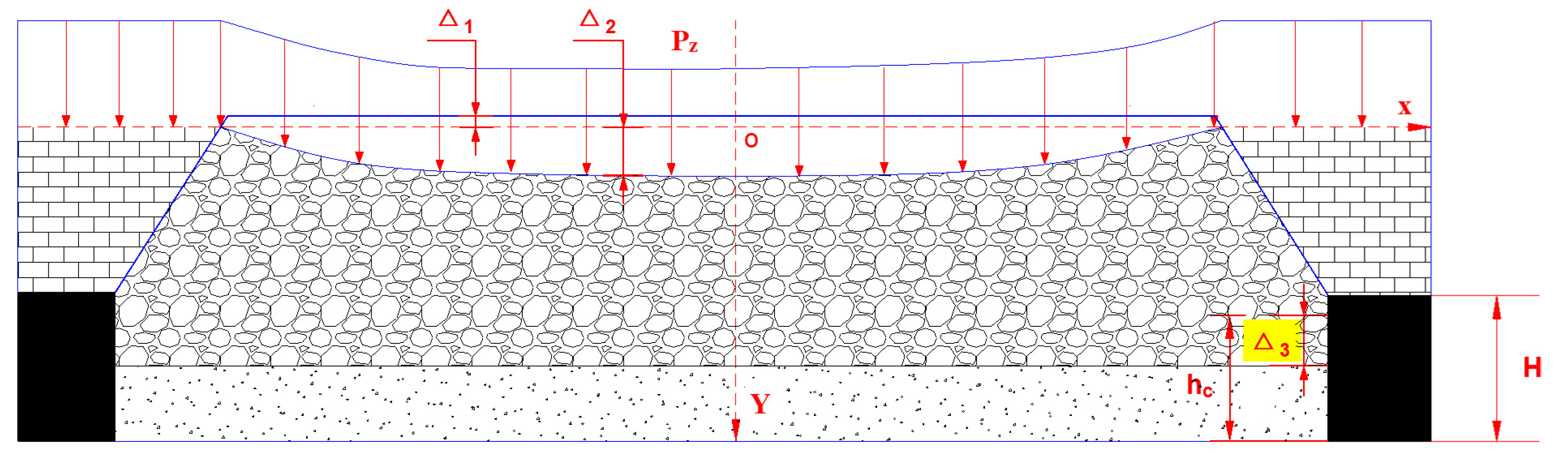
A mechanical model of overlying strata movement and migration in the PCFM was built, combined with the mechanics characteristic of the filling body in the localized paste filling mining and based on the basic hypothesis of elastic beams, as shown in Figure 2. As shown in Figure 2, O is the coordinate origin, X is for the inclination direction of working face, Y is for the vertical direction; is the load on main roof, (Pa); is the subsidence of main roof before the composite filling body reaches the strength, (m); is the compression amount of caving roof,(m); is the compression amount of paste filling body, (m); is the mining height, (m); is the filling height, (m).
According to E. Winkler’s hypothesis on foundation compaction and deformation: the subsidence at any point on the surface of the foundation is positively associated with the pressure per unit area at this point [30,31]:
Wherein: is the pressure per unit area, (Pa);
is the foundation settlement, (Pa);
is the foundation coefficient.
The analysis combined with the mechanical model diagram in Figure 3 finds that the subsidence value Z of main roof, load and counterforce of composite filling body meet the mechanics equation:
Wherein: E is the elastic modulus of main roof, (Pa);
is the moment of inertia of main roof (m4);
is the deflection curve of main roof;
is the foundation coefficient of composited filling body.
![Minerals 12 00654 g003]()
Figure 3.
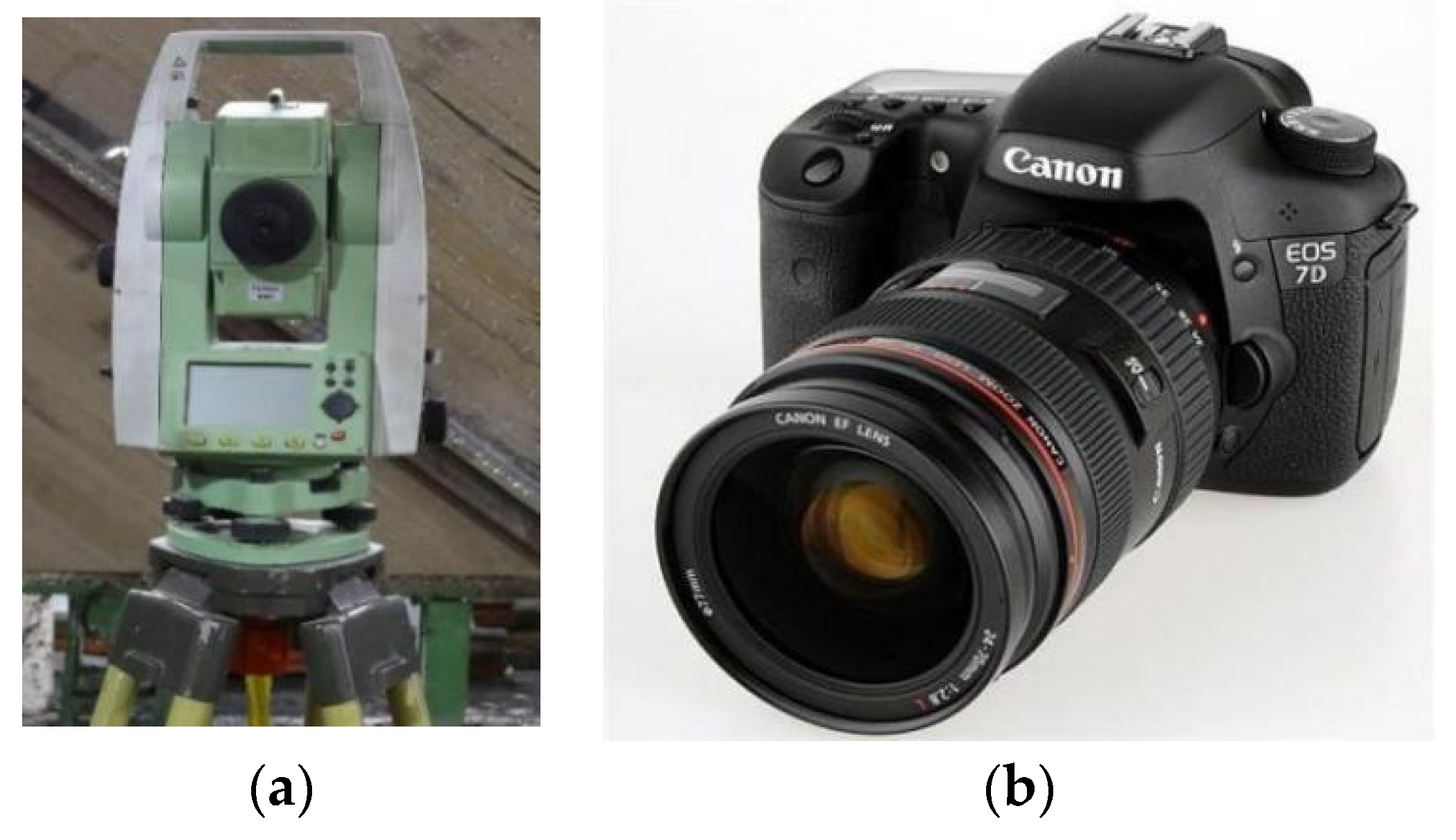
Monitoring equipment. (a) Optical total station, (b) high-speed camera.

Given , it can be deduced that main roof rock beams in the mined-out area under PCFM conditions apply to the subsidence curve equation:
Wherein: , , , are the constant.
As shown in Figure 3, the models on both sides of the coordinate axis were symmetric, and the part < 0 was analyzed. The model is the mechanical model of local elastic foundation beams, so x cannot be infinitely large. In other words, if x is infinitely large, . Thus, its analytical solution is obtained from:
According to the boundary conditions of the model: , , by substituting them into the Equation (4), we can get . The subsidence curve equation of main roof rock beams is as follows:
Through the analysis of the overlying strata stability in the paste filling mining, the major determinants to the overlying strata stability in the PCFM are: the subsidence of main roof , compression amount of caving roof , compression amount of paste filling body . The maximum subsidence of main roof applies to the constituent relation formula:
Due to the elasticity, the paste filling body will be compressed and deformed by dual actions of gravity of the caving immediate roof and subsequent roof pressure [9,32,33]. The amount of compression of paste filling body can be obtained by:
Wherein: ε is the compressive modulus of paste filling body.
The breakage of caving roof leads to volume expansion, so the piling height of caving coal wastes on the immediate roof is more than the original height of immediate roof. The falling mass is gradually compacted under the dead weight and the pressure of overlying strata and the bulking coefficient of rocks is reduced, so that failing rocks are compacted and deformed [34,35,36]. The amount of compression for the falling immediate roof can be expressed by:
Wherein: is the collapse height of immediate roof, m;
kp the residual dilatancy coefficient of caving immediate roof.
We get the expression of the maximum subsidence value for main roof:
The difference between the height after the remaining immediate roof bulking is broken and the thickness of complete strata before the immediate roof does not fall can be approximately equivalent to the amount of compression and deformation of caving strata height (). We can get the following relation formula:
Following the compression experiment made on broken immediate roof rocks, the compaction curve of broken immediate roof rocks is obtained. The research results show there are non-linear relations between the deformation amount and compacting force σ in the course of rock compaction.
Wherein: and
represent the proportionality coefficient of compaction curve of broken immediate roof rocks, representatively.
After the logarithm operation, we can get:
The compacting force can be seen as the load on the main roof overlying strata, that is:
Wherein: is the bulk density, N/m3.
We get the expression of the maximum subsidence value for main roof:
The solution is:
As such, after the analysis and computation of the model on the part , we can get:
Only when the mined-out area is fully compacted with composite filling body, the main roof strata can be stabilized and not be destroyed. For the main roof of different lithologies, the allowable maximum subsidence is different. The defined maximum subsidence corresponds to the only allowable maximum subsidence value. It is assumed that the allowable maximum subsidence value corresponding to the main roof is , the following formula can be used to judge the stability of overlying strata:
The solution is:
As shown in the Equation (17), because . and are constants, the major determinants causing the instability of overlying strata in the PCFM include the mining height, burial depth and filling ratio.
2.3. Physical Similarity Simulation Experiment
2.3.1. Model Establishment
This experiment took the geological conditions of the 112,208 working face of test coal mine as the research background, and used the two-dimensional similar simulation experimental frame to simulate the distribution characteristics of advance bearing pressure of coal wall, movement and deformation of roof rock stratum and the development law of overburden fractures in the process of advancing the working face. The length was selected according to the purpose of the experiment × wide × high = 3000 mm × 200 mm × 1800 mm. According to the size of the physical similarity simulation experiment frame, the geometric similarity constant was determined to be C = 150, and other similarity constants were selected according to the three similarity theorems and similarity criteria (see Table 2).
By analyzing the geological data of the working face 112,208 and the occurrence characteristics of coal strata, combined with the characteristics of similar materials, coal ash is selected as the main simulation material of coal seams, river sand, gypsum, and white powder are selected as the main aggregates of rock strata, and mica powder is used as the layered material to simulate the primary fractures between different rock strata. The proportion of similar materials is determined through calculation. Table 3 shows the proportion of similar materials.
According to Table 3, the corresponding quality of experimental materials was weighed, and the materials were fully mixed by manual mixing. After mixing, ingredients were filled immediately before conducting joint prefabrication for the simulated rock stratum after manual leveling and compaction, and finally, mica powder was sprinkled on the rock stratum surface to realize the stratification between the rock strata, directly top to the sub key layer, the filling thickness of the rock stratum was 1 cm each time, and the paving thickness of the remaining rock stratum was 1.5 cm each time. After the model was laid, it was placed for one week, then the channel steel outside the model was removed and the model was placed for 14 days to facilitate the rapid increase of model strength.
2.3.2. Experimental Monitoring Scheme and Equipment
The simulated stratum thickness was 253 m in total. The soil layer near the surface was replaced by an equivalent load. Twelve displacement measuring lines were arranged on the front of the model. The displacement value of the top measuring line during coal seam excavation was recorded by pentaxr-400nx total station, and the distribution characteristics and forms of transverse and longitudinal fractures of overburden during the whole experiment were recorded by high-speed camera. The experimental monitoring equipment is shown in Figure 3.
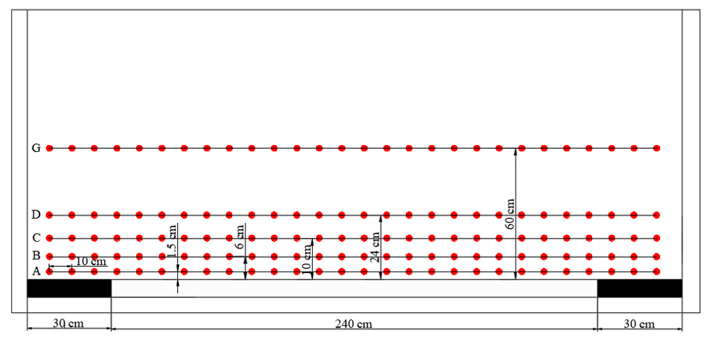
The specific survey line layout position is: 12 survey lines were arranged above the roof of 2-2 coal seam, and survey line A was arranged 1.5 cm above the roof of coal seam; 6 cm layout of survey line B; 10 cm survey line C; 24 cm layout survey line D; 45 cm layout survey line E; 50 cm layout survey line F; 60 cm layout survey line G; 72 cm survey line H; 80 cm layout survey line I; 90 cm layout survey line J. Among them, survey lines A and B were arranged at the lower and upper part of the basic top, survey lines C and D were arranged at the lower and upper part of the sub key layer respectively, and survey line G was arranged at the main key layer, as shown in Figure 4.
A total of 29 measuring points were arranged for each measuring line, corresponding to A1~A29 to L1~L29, and the horizontal spacing of measuring points was 10 cm. The total station was used to observe the displacement of measuring points during excavation.
2.4. Computer Numerical Simulation Experiment
UDEC6.0 numerical simulation software was used to establish the numerical model under different mining height, filling ratio and burial depth conditions to analyze the development process of overlying strata fractures during the advance of the working face. Origin software was used to fit the maximum development height of fractures under different mining conditions to obtain the function with respect to the development height of fractures under different mining heights, filling ratio, and burial depth conditions.
2.4.1. Model Establishment
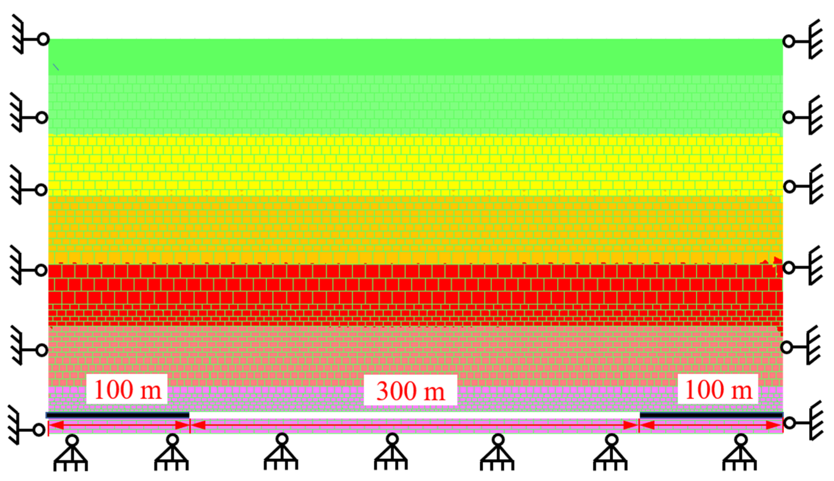
In order to analyze the development characteristics of overlying strata fractures in the localized PCFM under different mining heights, filling ratio, and burial depth conditions, the geological conditions of 112,201 working face of the test mine was taken and based on the mechanical parameters of coal and rock mass in the working face, the control variate method was used to build the numerical computation model as shown in Figure 5. The development laws of overlying strata fractures were investigated by using mining height, filling ratio, and burial depth as the determinants.
2.4.2. Boundary Conditions and Model Excavation
The bottom, left and right boundaries of the model were fixed to limit the boundary movement. In the research of the PCFM, vertical and downward stress at 1.25 MPa, 2.5 MPa and 3.75 MPa were applied on the surface of the model to stimulate the burial depth of 300 m, 350 m and 400 m, respectively. The constitutive model of coal and rock mass selected the Mohr–Coulomb model, and the corresponding joint fracture model was also the Mohr–Coulomb model [37]. A 100 m coal pillar was left on either side of the model separately to reduce the boundary effects caused by the excavation of the model. The working face was filled while it was being mined, and the overall excavation distance of the model was 300 m, with an excavation of 5 m per time.
3. Results and Discussion
3.1. Physical Similarity Simulation Experiment Results
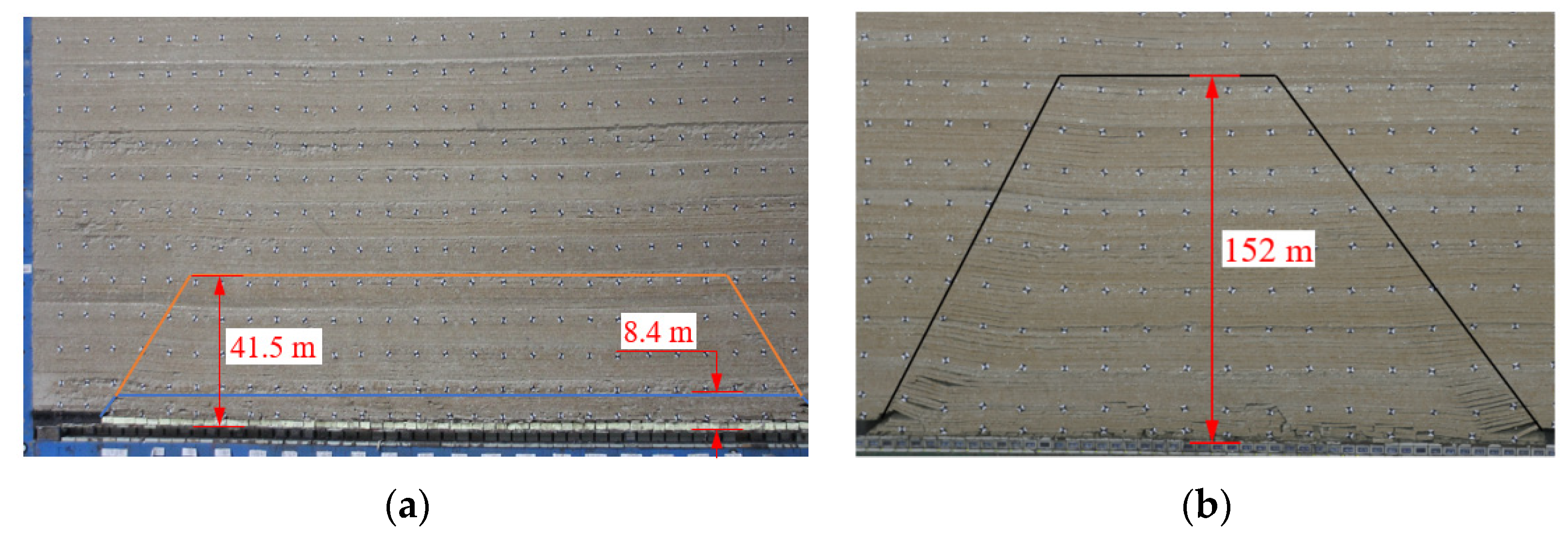
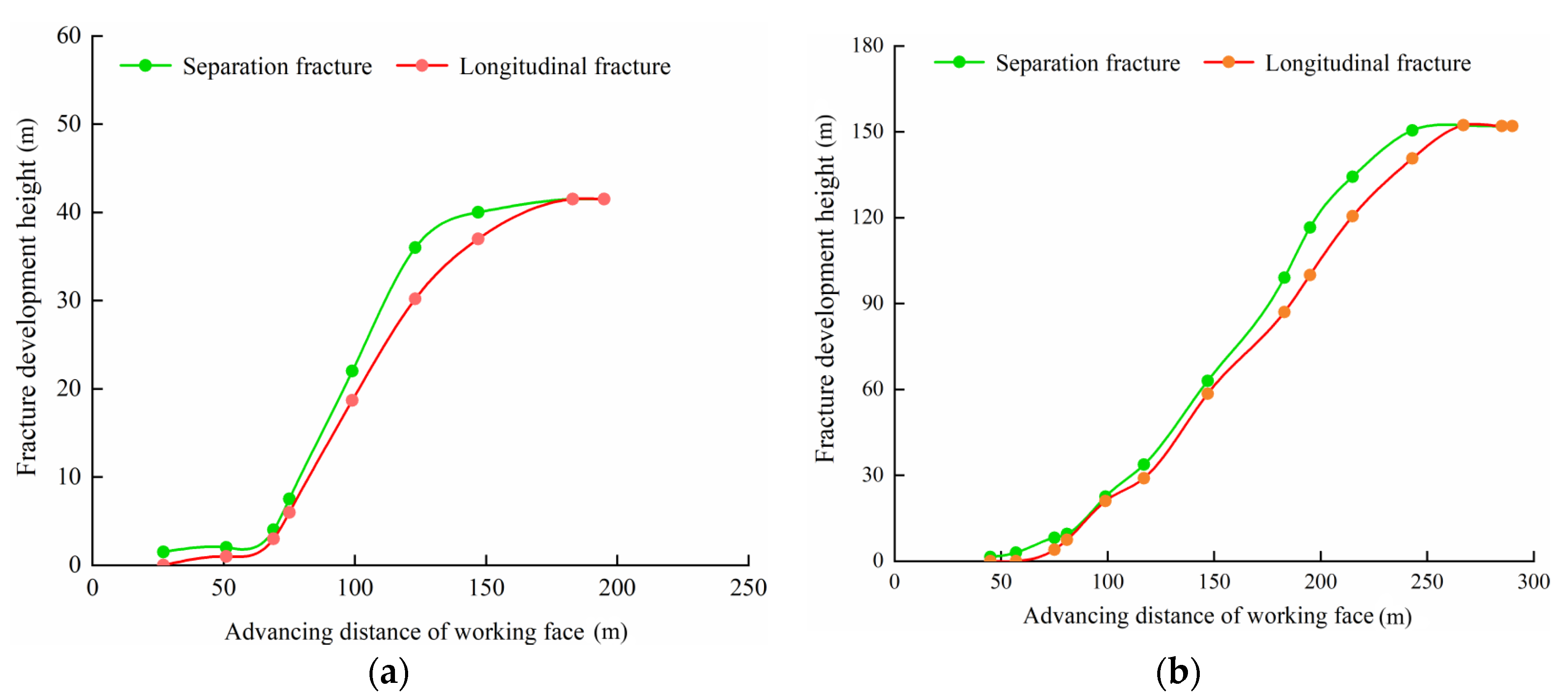
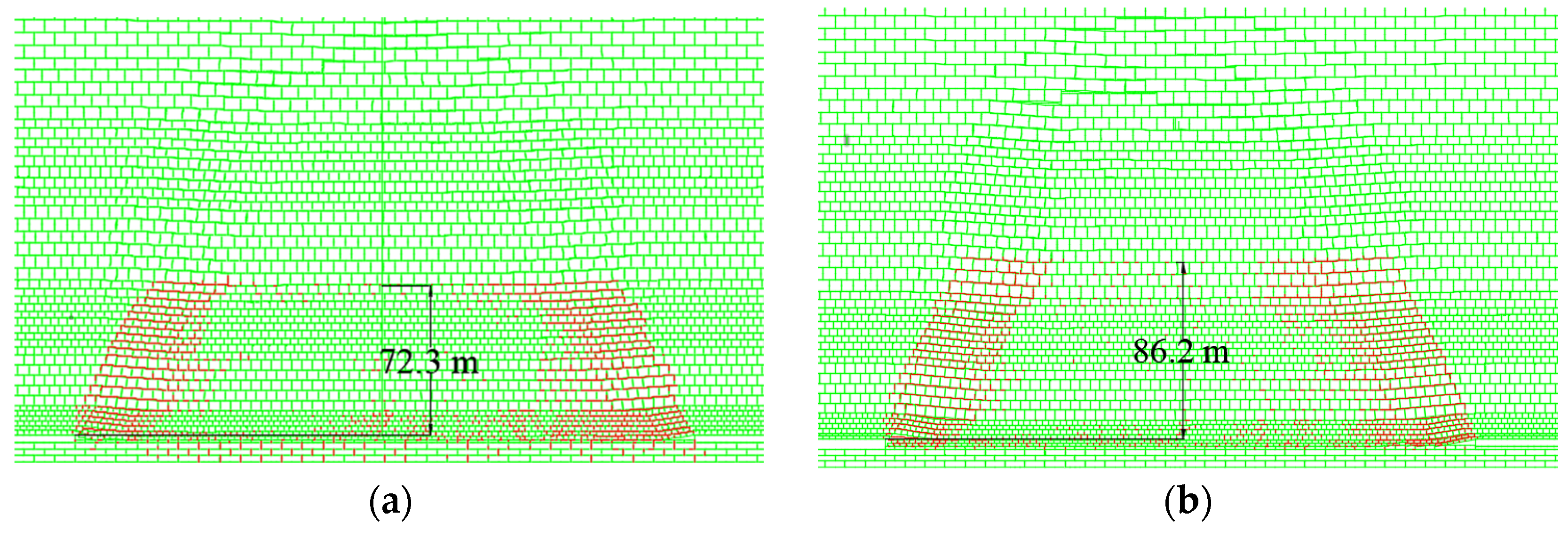
Figure 6 illustrates the physical similarity simulation experiment for the development characteristics of overlying strata fractures in the PCFM and caving mining. It can be seen from Figure 7 that for the caving mining, as the roof strata are stable, overlying strata fractures are barely developed longitudinally at the early stage of working face advance. When the working face was advanced to 40 m, transverse fractures occurred on the immediate roof, which is in the rapid fracture rise area when it is at the middle stage of working face advance (working face advance within 120–200 m). In this area, the height of overlying strata fractures increases in a linear manner. At the end of the working face advance, as the upper overlying strata in the mined-out area are fully disturbed, the lower overlying strata fractures are gradually compacted to form a closure. This makes the upper overlying strata fractures slowly developed and their height tends to be of a stable value. After the whole working face was completed, the development height of longitudinal overlying strata fractures was 152 m. Under the conditions of 2/3 filling mining, the curve pattern of fracture development height was similar to that of caving mining, showing an apparent fracture development at the early stage of advance, rapid fracture expansion stage, and slow rise and stabilization stage. However, different from the caving mining, the working face had a lower fracture development height, and the location where the fracture reached the maximum height is close to the open-off cut. When the working face was advanced to 51 m, the fracture height of the separation layer was 4 m. When the working face was advanced to 147 m, the height of the overlying strata fracture drastically increased to 40 m. Further, in the case of the advance from 147 m to 220 m, the height of overlying strata fracture slowly increased from 40 m to 41.5 m. Under the conditions of 2/3 filling mining, overlying strata fractures can only penetrate through the sub-key stratum to form the dominant longitudinal fracture in the mined-out side. From the above analysis, it can be seen that due to the addition of fillings in the mined-out area, a new “support-surround rock-composite filling body” dynamic working space was formed in the filling stope where the morphology of overlying strata development has new characteristics and fracture height is significantly reduced [38,39,40].
3.2. Computer Numerical Simulation Results
3.2.1. Development Characteristics of Overlying Strata Fractures under Different Mining Height Conditions
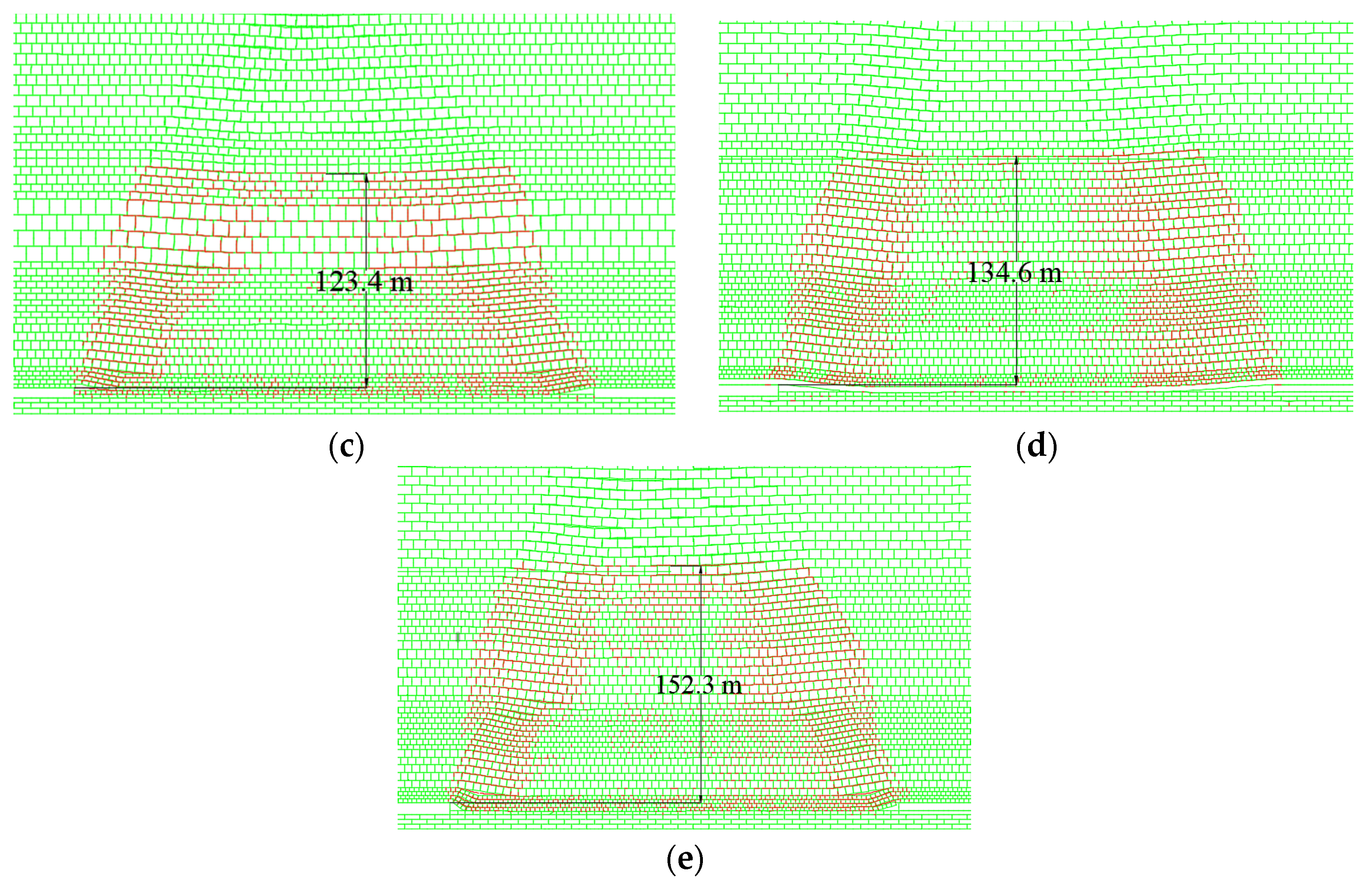
To analyze the effects of the mining height of working face on the development of overlying strata fractures during the PCFM, numerical simulation analysis was made by changing the mining height. The results were reported in Figure 8. From this Figure 6, we can see that the fracture evolution has similar characteristics during the advance of working face under different mining height conditions (4 m, 5 m, 6 m, 7 m, 8 m), and the distribution of overlying strata fractures is extended and expanded forward and upward as the working face is advanced. The fracture evolution process can be divided into 3 stages. Stage I is the occurrence of fractures, Stage II is the expansion of fractures, and Stage III represents the compaction of fractures. Before the main roof is initially broken, the roof fractures are mainly transverse separation fractures. During the advance of the working face, the subsidence occurs in the separation roof, with partially longitudinal fractures in the middle of the roof. After the main roof is initially broken, a separation layer occurs in the overlying strata, and a large number of fractures that are evenly distributed are formed above the coal wall on both sides of the mined-out area. At the middle stage of working face mining, the periodic failure occurs in the main roof, and the overlying strata fractures continue to be expanded upward, with the separation fracture always higher than the longitudinal fracture. At the end stage, the fractures in the middle of overlying strata were compacted to form a closure, which are mainly located on both sides of the mined-out area.
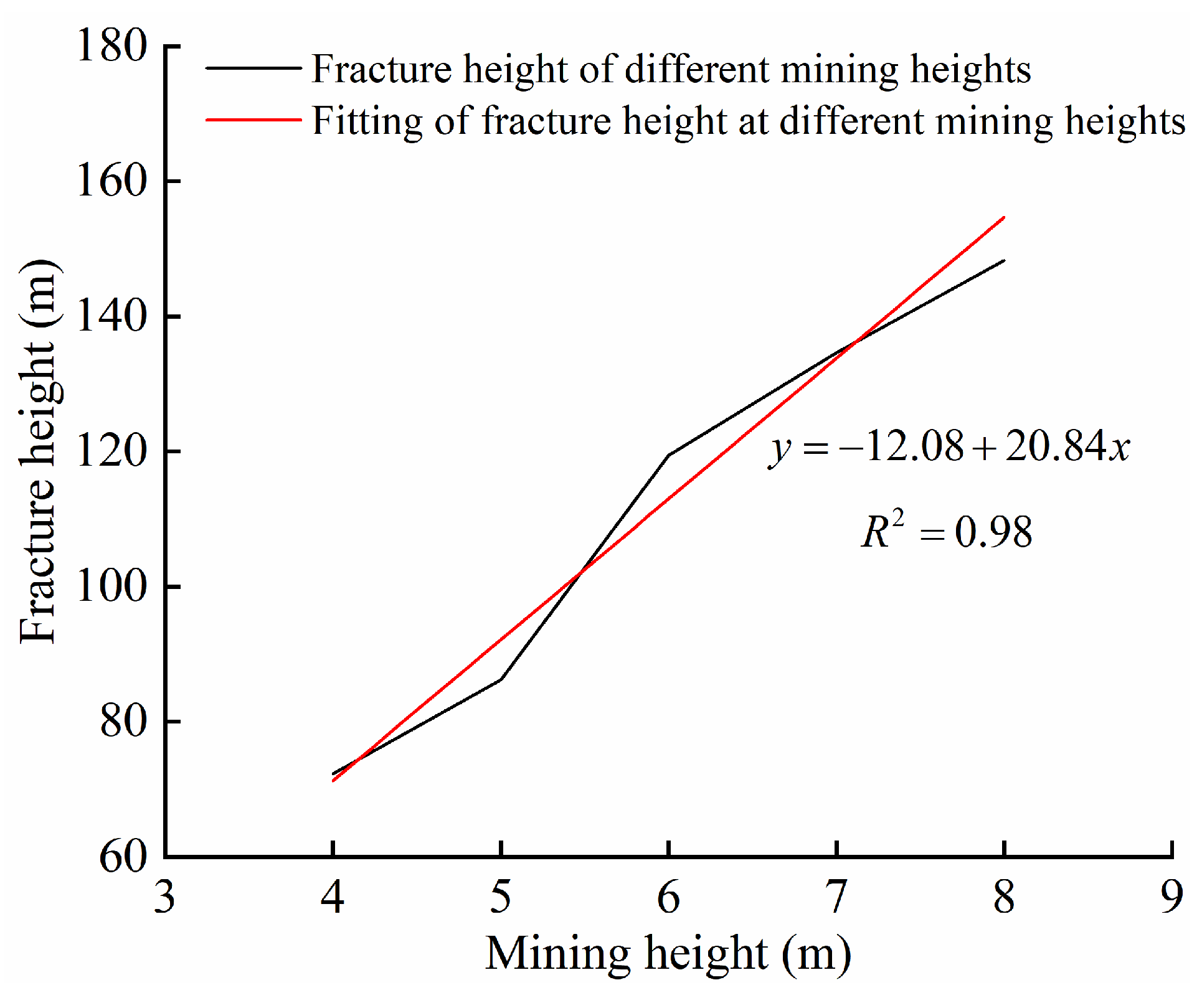
Figure 9 shows the fit curve of the development height of overlying strata fractures under different mining height conditions. It can be seen from Figure 9 that the development height of overlying strata fractures increases linearly as the mining height of working face increases. When the mining height of coal seams is smaller, the unfilled space is narrow, but its volume will be enlarged after the roof is broken, with the whole mined-out area being filled with broken coal wastes. This enables a small scope of caving zone formed above the roof after the coal seam is mined to better support the overlying strata, so that the movement scope of overlying strata will be reduced and the development height of fractures will be lowered accordingly. When the mining height of coal seams increases, the unfilled space is larger. The whole mined-out area will not be filled with falling roof, and thus the height of the caving zone increases, so that the height of overlying strata fractures also increases accordingly, and the fractures are mainly distributed on both sides of the coal wall and the upper part of overlying strata.
3.2.2. Development Characteristics of Overlying Strata Fractures under Different Filling Ratio Conditions
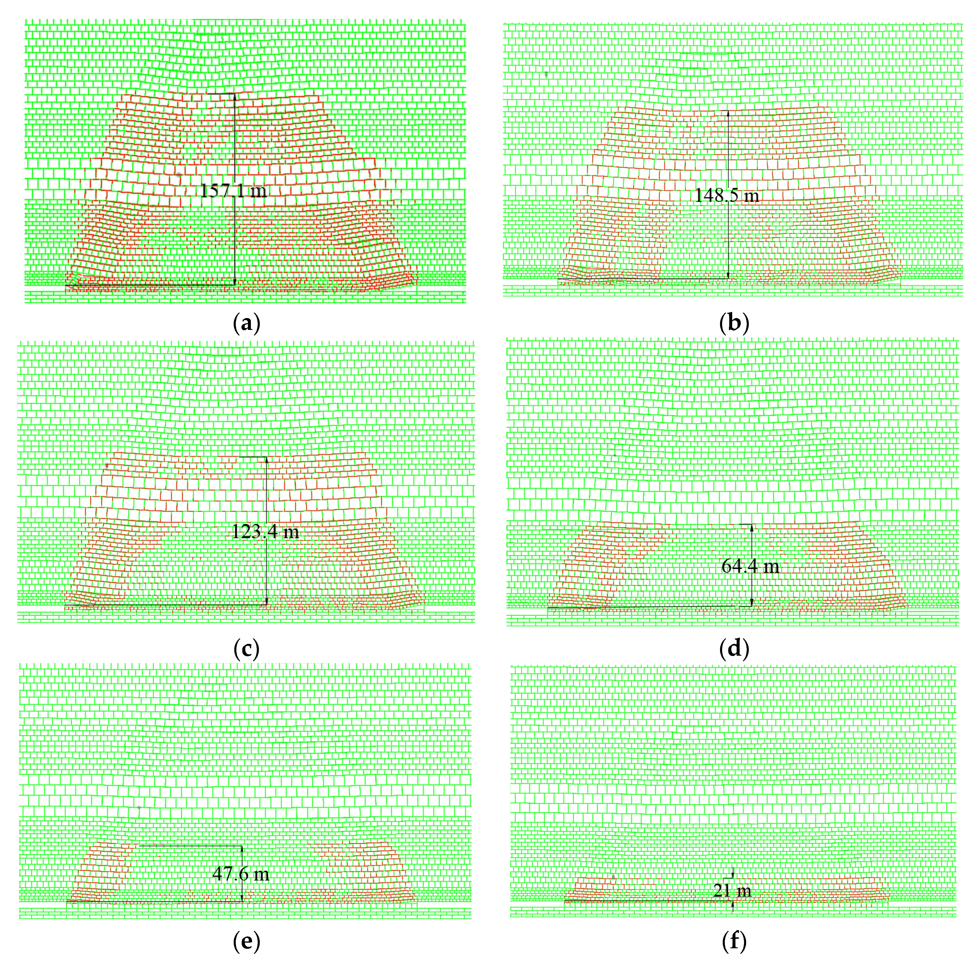
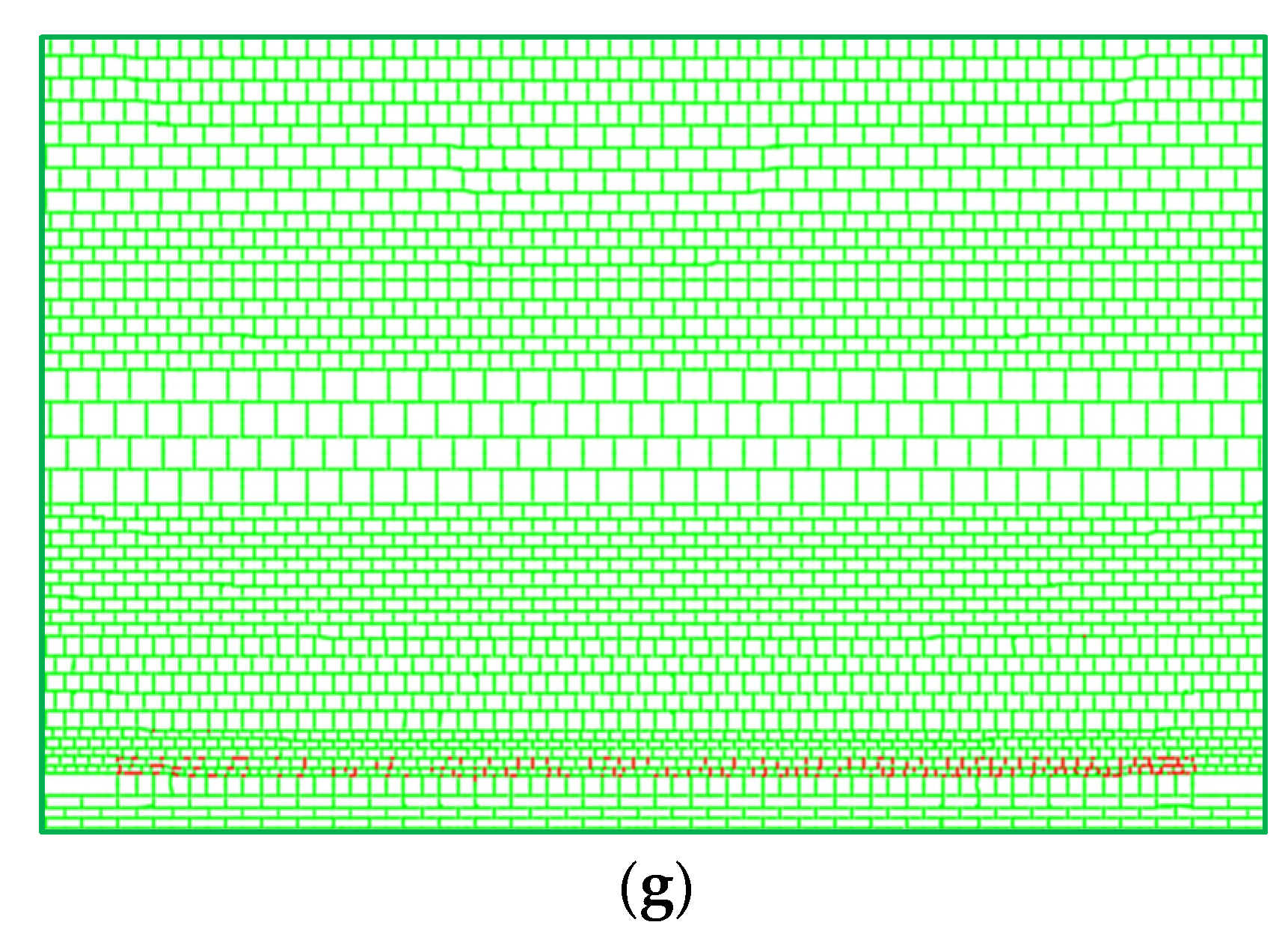
Figure 10 illustrates the development characteristics of overlying strata fractures under different filling ratio conditions (0, 1/5, 1/3, 1/2, 2/3, 3/4, 1). In Figure 10, the development process of overlying strata fractures is similar under different filling ratio conditions, and the fractures are mainly distributed in both sides of coal wall and within overlying strata. When the filling ratio is larger, the development height and distribution range of overlying strata fractures are smaller. As the working face was advanced, overlying strata slowly subsided, separation fractures were generally developed, and few longitudinal fractures were formed in the bending and subsidence of strata. After the overall working face was completed, the roof had a smaller scope of breakage and failure, and overlying strata fractures were mainly distributed in overlying strata on both sides of the coal wall to form the dominant water-flowing fractures with the horizontal fractures substantially being compacted and closed. When the filling ratio reaches 100%, the bending and subsidence occurred at 2~6 m above the roof of the mined-out area, fine longitudinal fractures were generated on rock beams but not formed into penetrating fractures.
According to Figure 11, as the paste filling ratio of working face increases, the development height of overlying strata fractures is generally reduced. The development height curve of the fractures is divided into 3 stages. Stage I is the slow reduction area of the fracture height. At this stage, when the filling ratio is smaller than 1/3, the height of the overlying strata fractures is slowly reduced, and the degree of reduction is small and 21.4%. Stage II is the rapid reduction area of the fracture height. When the filling ratio of the working face is 1/3~3/4, the development height of the overlying strata fractures is quickly reduced, and the degree of reduction increases to 65.2%. Stage III is the slow reduction area of the fractures. At this stage, the degree of reduction of the fracture height is 13.4%. Theoretically, when the filling ratio reaches 100%, fewer fractures will occur in the overlying strata. However, in the actual production, the filling ratio of the working face cannot reach 100% due to the limitation of various reasons. The above analysis indicates that when the filling ratio is 1/3~3/4, the development of the overlying strata fractures is better controlled and the economic rationality is also better.
3.2.3. Development Characteristics of Overlying Strata Fractures under Different Burial Depth Conditions
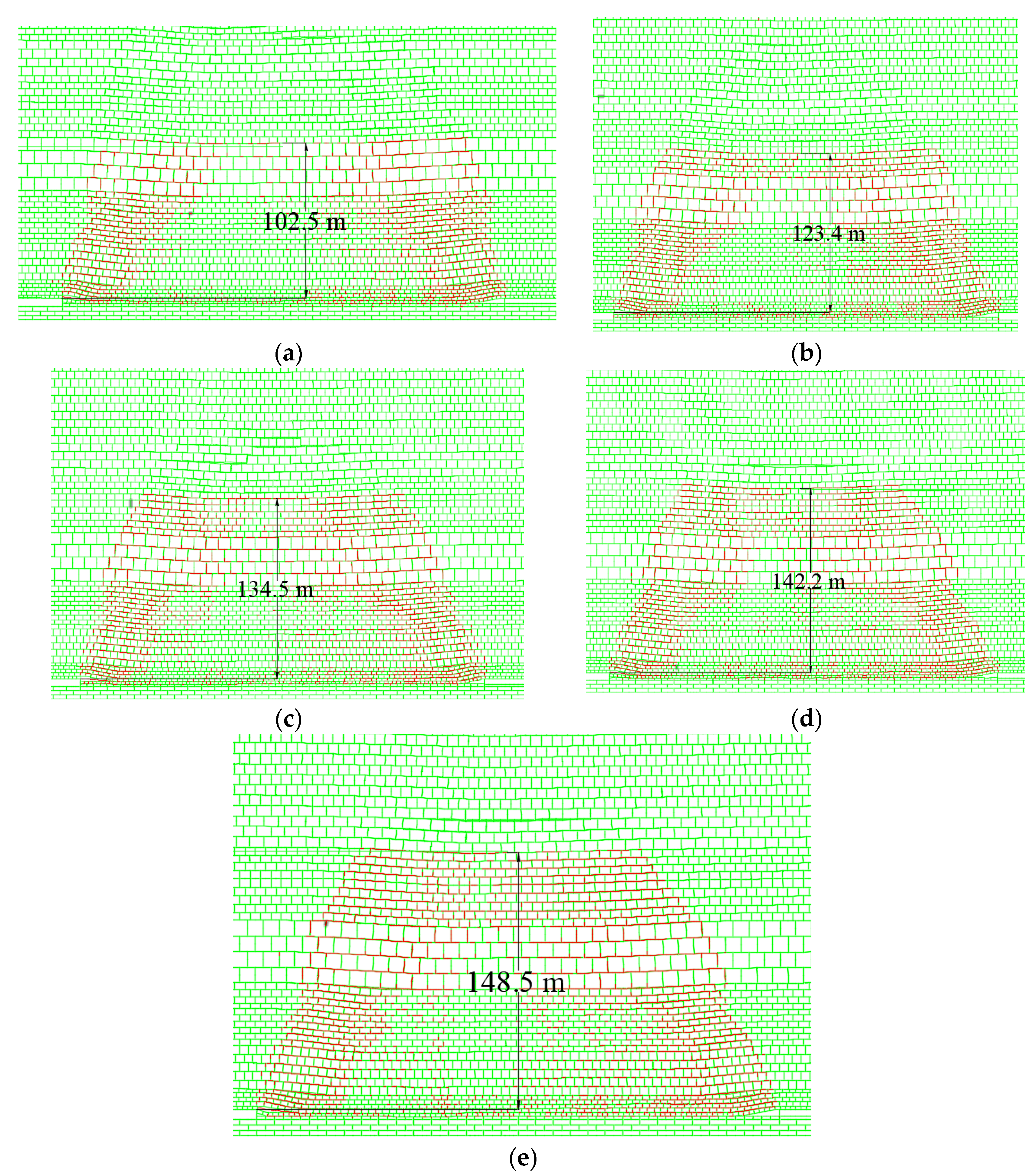
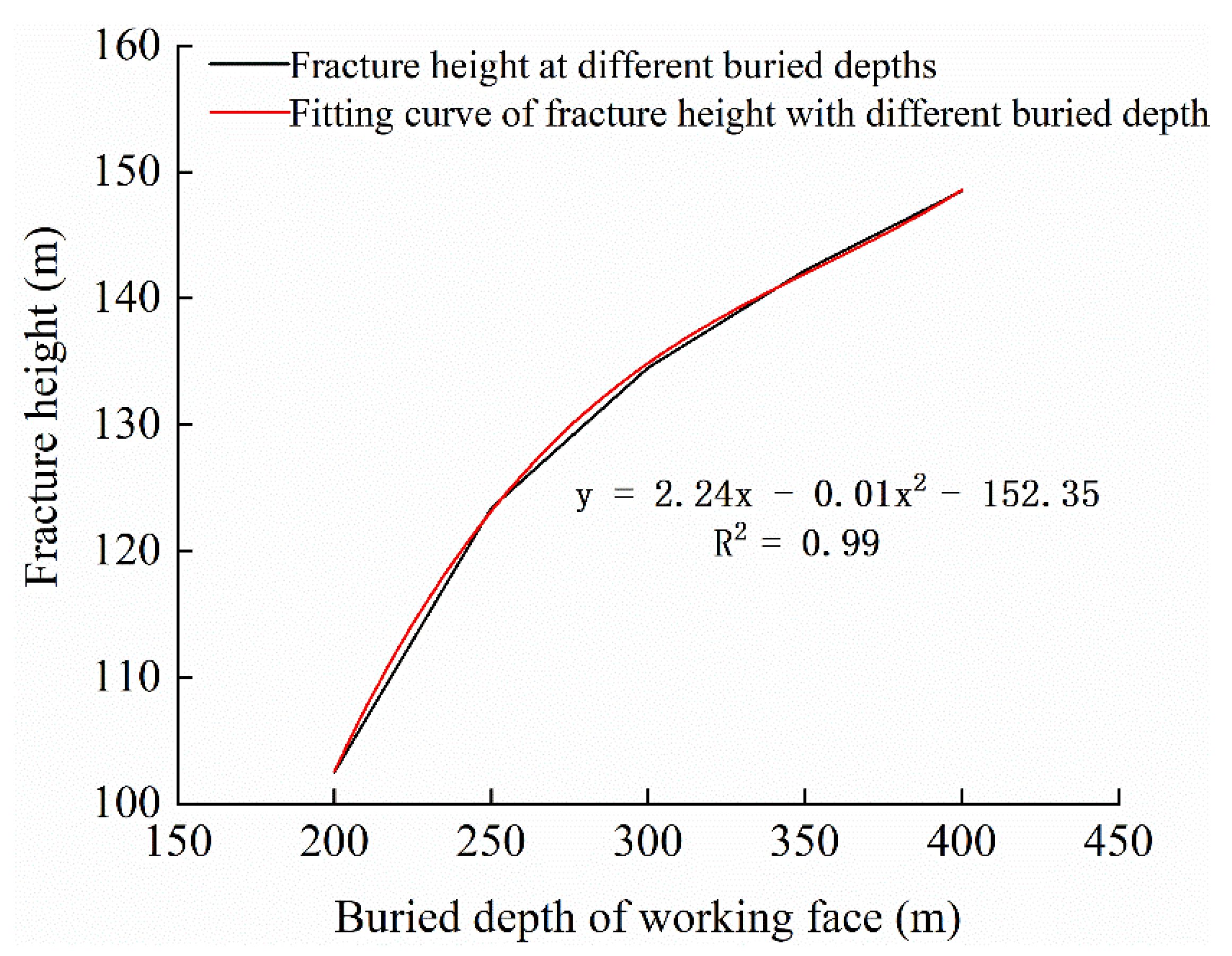
Figure 12 displays the development characteristics of the overlying strata fractures in different burial depth conditions (200 m, 250 m, 300 m, 350 m, 400 m). It can be seen from Figure 12 that the development laws of overlying strata fractures are similar in the working face under different burial depth conditions. As the working face is advanced, the overlying strata are first developed with the horizontal separation fractures and then vertical fractures prevailing. The shallower the burial depth is, the faster the fractures are developed to the maximum height. As the burial depth increases, the development of the overlying strata fractures to the maximum height gradually slows down.
As shown in Figure 13, as the burial depth of working face increases, the overlying strata fractures are increasingly developed. When the burial depth of working face is shallower, the rocks within the caving zone are applied with small overlying strata pressure, and the degree of compaction on the caving roof is lower, together with the small separation interval, leading to the small development height of overlying strata fractures. When the burial depth of coal seams in the working face is larger, the overlying strata are applied with a large pressure, and the degree of compaction on the caving roof is higher, leading to large fractures within the caving zone and leaving a large movement space for the overlying strata. This provides the large development height and scope of overlying strata fractures. The height of overlying strata fractures will not infinitely increase with the increase of the burial depth of the working face, because the space resulting from the PCFM and the compressibility of caving rocks are fixed values. Therefore, as the burial depth of the working face continues to increase, the overlying strata fractures will gradually tend to be a stable value.
4. Conclusions
(1) By analyzing the stress characteristics of the filling body during the PCFM, the mechanical model of the roof movement is established. Through the analysis of the overburden stability, it is determined that the mining height, filling ratio and buried depth of the working face are the main influencing factors.
(2) By analyzing the experimental results of unfilled mining and filling 2/3 mining through physical similarity simulation experiments, it can be seen that the fracture development processes are similar, which include four stages: fracture initiation—rapid expansion—slow extension—compaction and closure. When the caving method is used to mine the coal seam, the maximum development height of overburden fracture after the mining of the working face is 150.5 m. Compared with the caving method when the filling ratio of the working face is 2/3, the maximum height of overburden fracture is 40 m. The PCFM can effectively reduce the overburden collapse height and fracture development height.
(3) Through the UDEC numerical simulation, the influence characteristics of mining height, filling ratio, and buried depth on the development of overburden fractures in PCFM are studied. The research results show that mining height, filling ratio, and buried depth have a great influence on overburden fractures. With the increase of mining height, the fracture height of the overburden increases linearly with the mining height. When the mining heights of the coal seam are 4 m and 5 m, the fractures are mainly distributed on both sides of the coal wall; when the mining heights of the coal seam are 6 m, 7 m and 8 m, the overburden fractures are mainly distributed on both sides of the coal wall and the upper part of the overburden; when the filling ratios are 1/2, 2/3, 3/4 and 100%, the development height (64.4 m, 47.6 m, 21 m and 5 m) and distribution range of overburden fractures are small. With the increase in the filling ratio of the working face, the fracture height of overburden decreases. The shallower the buried depth is, the faster the crack develops to the maximum height. With the increase of buried depth, the range of overburden fracture zone is also expanding.
(4) For a specific mine under the conditions of certain mining height, buried depth and filling ratio, the development height of the overburden fracture can be determined through a physical similarity simulation experiment, numerical simulation experiment, and field measurement to judge whether the height of overburden fracture reaches the height of overburden water resisting layer. This study provides an important theoretical basis for examining the conditions for water burst occurrence and water burst prediction during the mining and for developing countermeasures for mine water disaster prevention.
Author Contributions
Conceptualization, W.L. and H.W.; supervision, W.L.; funding acquisition, methodology, W.L.; numerical calculation, H.W.; data curation, D.J. and K.F.; writing—original draft preparation, K.G. and H.W.; physical similarity simulation experiment, H.W. and K.G. All authors have read and agreed to the published version of the manuscript.
Funding
This research was funded by the National Natural Science Foundation of China (No. 52174127, 51974226), the Research Fund of Henan Key Laboratory for Green and Efficient Mining & Comprehensive Utilization of Mineral Resources (Henan Polytechnic University, No. KCF202001), the Research Fund of Shaanxi Key Laboratory of Coal Mine Water Disaster Prevention and Control Technology (No. 2020SKMS02), and the Major Science and Technology Innovation Projects in Shandong Province (No. 2019JZZY020326).
Institutional Review Board Statement
This study does not require ethical approval, so this statement is excluded.
Informed Consent Statement
Informed consent was obtained from all subjects involved in the study.
Data Availability Statement
The data provided in this study can be obtained at the request of the corresponding author.
Acknowledgments
This work was supported by the National Natural Science Foundation of China (No. 52174127, 51974226), the Research Fund of Henan Key Laboratory for Green and Efficient Mining & Comprehensive Utilization of Mineral Resources (Henan Polytechnic University, No. KCF202001), the Research Fund of Shaanxi Key Laboratory of Coal Mine Water Disaster Prevention and Control Technology (No. 2020SKMS02), and the Major Science and Technology Innovation Projects in Shandong Province (No. 2019JZZY020326).
Conflicts of Interest
The authors declare no conflict of interest.
References
- Huang, Q.X.; Du, J.W.; Chen, J.; He, Y.P. Coupling Study on strata control based on pillar stress concentration and surface cracks in shallow multi-seam mining. Int. J. Min. Sci. Technol. 2021, 31, 95–101. [Google Scholar] [CrossRef]
- Qian, M.G.; Xu, J.L.; Miao, X.X. Green mining technology in coal mine. J. China Univ. Min. Technol. 2003, 32, 343–348. [Google Scholar]
- Wang, S.M.; Sun, Q.; Qiao, J.W.; Wang, S.Q. Geological guarantee of coal green mining. J. China Coal Soc. 2020, 45, 8–15. [Google Scholar]
- Wang, S.M. Coal Accumulating and Coal Resource Evaluation of ORDOS Basin; China Coal Industry Publishing House: Beijing, China, 1996. [Google Scholar]
- Wen, P.; Guo, W.; Tan, Y.; Bai, E.; Ma, Z.; Wu, D.; Yang, W. Paste backfilling longwall mining technology for thick coal seam extraction under buildings and above confined aquifers: A case study. Minerals 2022, 12, 470. [Google Scholar] [CrossRef]
- Qiu, H.F.; Zhang, F.S.; Liu, L. Experimental study on acoustic emission characteristics of cemented rock-tailings backfill. Constr. Build. Mater. 2022, 315, 125278. [Google Scholar] [CrossRef]
- Kostecki, T.; Spearing, A.J.S. Influence of backfill on coal pillar strength and floor bearing capacity in weak floor conditions in the Illinois Basin. Int. J. Rock Mech. Min. 2015, 76, 55–67. [Google Scholar] [CrossRef]
- Khaldoun, A.; Ouadif, L.; Baba, K.; Bahi, L. Valorization of mining waste and tailings through paste backfilling solution, Imiter operation, Morocco. Int. J. Min. Sci. Technol. 2016, 26, 146–151. [Google Scholar] [CrossRef]
- Zhang, J.; Deng, H.; Taheri, A.; Deng, J.; Ke, B. Effects of superplasticizer on the hydration, consistency, and strength development of cemented paste backfill. Minerals 2018, 8, 381. [Google Scholar] [CrossRef] [Green Version]
- Xu, J.L.; Xuan, D.Y.; Zhu, W.B.; Wang, X.Z. Partial backfilling coal mining technology based on key strata control. J. Min. Strata Control Eng. 2019, 1, 013504. [Google Scholar]
- Zhang, P.F.; Zhao, T.B.; Ma, X.Y.; Fu, Z.Y.; Tian, X.G.; Li, Z.H. Analysis on crack distribution and evolution characteristics of gangue backfilled working face roof. Chin. J. Rock. Mech. Eng. 2022, 41, 969–978. [Google Scholar] [CrossRef]
- Chen, S.J.; Guo, W.J.; Zhou, H.; Wen, G.H. Structure model and movement law of overburden during strip pillar mining backfill with cream-body. J. China Coal Soc. 2011, 36, 1081–1086. [Google Scholar]
- Guo, G.L.; Guo, K.K.; Zhang, G.J.; Li, H.Z. Research on deformation characteristics of coupled coal-backfills bearing in deep strip backfilling mining. J. Min. Saf. Eng. 2020, 37, 101–108. [Google Scholar]
- Li, J. Evolution Mechanical and Control of Water-Flowing Fracture with Gangue Backfill under Aquifer in Coal Mines. Ph.D. Thesis, China University of Mining & Technology, Xuzhou, China, 2013. [Google Scholar]
- Yang, G.; Hang, Y.; Zhang, J.C.; Zhao, Q.J. Study on overburden failure numerical simulation in paste—Like material backfill mining. Coal Geol. China 2021, 33, 56–60. [Google Scholar]
- Lv, W.Y.; Wu, Y.P.; Liu, M.; Yin, J.H. Migration Law of the Roof of a Composited Backfilling Longwall Face in a Steeply Dipping Coal Seam. Minerals 2019, 9, 188. [Google Scholar] [CrossRef] [Green Version]
- Helinski, M.; Fahey, M.; Fourie, A. Behavior of cemented paste backfill in two mine stopes: Measurements and modeling. J. Geotech. Geoenviron. 2010, 137, 171–182. [Google Scholar] [CrossRef]
- Ivannikov, A.L.; Kongar-Syuryun, C.; Rybak, J.; Tyulyaeva, Y. The reuse of mining and construction waste for backfill as one of the sustainable activities. IOP Conf. Ser. Earth Environ. Sci. 2019, 362, 012130. [Google Scholar] [CrossRef]
- Kongar-Syuryun, C.; Tyulyaeva, Y.; Khairutdinov, A.M.; Kowalik, T. Industrial waste in concrete mixtures for construction of underground structures and minerals extraction. IOP Conf. Ser. Mat. Sci. Eng. 2020, 869, 032004. [Google Scholar] [CrossRef]
- Khairutdinov, A.; Ubysz, A.; Adigamov, A. The concept of geotechnology with a backfill is the path of integrated development of the subsoil. IOP Conf. Ser. Earth Environ. Sci. 2021, 684, 012007. [Google Scholar]
- Kongar-Syuryun, C.; Ubysz, A.; Faradzhov, V. Models and algorithms of choice of development technology of deposits when selecting the composition of the backfilling mixture. IOP Conf. Ser. Earth Environ. Sci. 2021, 684, 012008. [Google Scholar] [CrossRef]
- Hefni, M.; Hassani, F. Effect of air entrainment on cemented mine backfill properties: Analysis based on response surface methodology. Minerals 2021, 11, 81. [Google Scholar] [CrossRef]
- Hefni, M.; Ali, M.A. The Potential to Replace Cement with Nano-Calcium Carbonate and Natural Pozzolans in Cemented Mine Backfill. Adv. Civ. Eng. 2021, 2021, 5574761. [Google Scholar] [CrossRef]
- Al-Moselly, Z.; Fall, M.; Haruna, S. Further insight into the strength development of cemented paste backfill materials containing polycarboxylate ether-based superplasticizer. J. Build. Eng. 2022, 47, 103859. [Google Scholar] [CrossRef]
- Ali, G.; Fall, M.; Alainachi, I. Time- and Temperature-Dependence of Rheological Properties of Cemented Tailings Backfill with Sodium Silicate. J. Mater. Civ. Eng. 2021, 33, 04020498. [Google Scholar] [CrossRef]
- Yilmaz, T.; Ercikdi, B.; Deveci, H. Utilisation of construction and demolition waste as cemented paste backfill material for underground mine openings. Environ. Manag. 2018, 222, 250–259. [Google Scholar] [CrossRef]
- Yılmaz, T.; Ercikdi, B. Effect of construction and demolition waste on the long-term geo-environmental behaviour of cemented paste backfill. Int. J. Environ. Sci. Technol. 2021, 19, 3701–3714. [Google Scholar] [CrossRef]
- Yilmaz, E.; Belem, T.; Benzaazoua, M. Effects of curing and stress conditions on hydromechanical, geotechnical and geochemical properties of cemented paste backfill. Eng. Geol. 2014, 168, 23–37. [Google Scholar] [CrossRef]
- Bai, E.H.; Guo, W.B.; Tan, Y.; Huang, G.S.; Guo, M.J.; Ma, Z.B. Roadway backfill mining with super-high-water material to protect surface buildings: A case study. Appl. Sci. 2020, 10, 107. [Google Scholar] [CrossRef] [Green Version]
- Wang, R.; Cao, W.; Brandenberg, S.; Zhang, J.M. Method for calculating axial force and settlement of pile foundation in consolidating and reconsolidating ground. Chin. J. Geotech. Eng. 2015, 37, 512–518. [Google Scholar]
- Yu, H.T.; Cai, J.; Zhang, Z.W. Analytical solutions for long tunnels under arbitrary dynamic loading. J. Tongji Univ. Nat. Sci. Ed. 2018, 46, 1–6. [Google Scholar]
- Sui, W.; Zhang, D.; Cui, Z.C.; Wu, Z.; Zhao, Q. Environmental implications of mitigating overburden failure and subsidences using paste-like backfill mining: A case study. Int. J. Min. Reclam. Environ. 2015, 29, 521–543. [Google Scholar] [CrossRef]
- Sheshpari, M. A review of underground mine backfilling methods with emphasis on cemented paste backfill. Electron. J. Geotech. Eng. 2015, 20, 5183–5208. [Google Scholar]
- Xie, P.S.; Wu, Y.P.; Luo, S.H.; Wang, H.W.; Lang, D. Evolution and stability analysis of inclined bench structure in large dip and high mining height stope. Chin. J. Rock Mech. Eng. 2018, 35, 953–959. [Google Scholar]
- Yao, Q.; Feng, T.; Liao, Z. Instability mechanism and reasonable size of sharply inclined segmented filling column. J. Min. Saf. Eng. 2018, 35, 49–57. [Google Scholar]
- Wu, Y.P. Basic Research on Dynamic Control of “R-S-F” System in Large Dip Seam Mining; Shaanxi Science and Technology Press: Xi’an, China, 2003. [Google Scholar]
- Lu, L.J.; Li, T.B.; Wang, G.; Wu, X.Z.; Jiang, Y.J.; Han, Z.Z. Crack expansion judgment method in overlying strata and its application for coal mining under aquifers. J. China Coal Soc. 2014, 39, 301–307. [Google Scholar]
- Jafari, M.; Shahsavari, M.; Grabinsky, M. Experimental study of the behavior of cemented paste backfill under high isotropic compression. J. Geotech. Geoenviron. Eng. 2020, 146, 06020019. [Google Scholar] [CrossRef]
- Ke, X.; Zhou, X.; Wang, X.S.; Wang, T.; Hou, H.B.; Zhou, M. Effect of tailings fineness on the pore structure development of cemented paste backfill. Constr. Build. Mater. 2016, 126, 345–350. [Google Scholar] [CrossRef]
- Chang, Q.; Chen, J.; Zhou, H.; Bai, J. Implementation of paste backfill mining technology in Chinese coal mines. Sci. World J. 2014, 2014, 821025. [Google Scholar] [CrossRef]
Figure 1.
Schematic diagram of PCFM.

Figure 2.
Mechanical model diagram for PCFM.

Figure 4.
Layout of physical model displacement measuring line.

Figure 5.
The numerical computation model.

Figure 6.
Development characteristics of overlying strata fractures. (a) PCFM; (b) Caving mining.

Figure 7.
Overlying strata fracture development height. (a) PCFM; (b) Caving mining.

Figure 8.
Development characteristics of overlying strata fractures under different mining height conditions. (a) Mining Height 4 m; (b) Mining Height 5 m; (c) Mining Height 6 m; (d) Mining Height 7 m; (e) Mining Height 8 m.
Figure 8.
Development characteristics of overlying strata fractures under different mining height conditions. (a) Mining Height 4 m; (b) Mining Height 5 m; (c) Mining Height 6 m; (d) Mining Height 7 m; (e) Mining Height 8 m.


Figure 9.
The fit curve of the development height of overlying strata fractures under different mining height conditions.
Figure 9.
The fit curve of the development height of overlying strata fractures under different mining height conditions.

Figure 10.
The development characteristics of overlying strata fractures under different filling ratio conditions. (a) Un-filling; (b) Filling 1/5; (c) Filling 1/3; (d) Filling 1/2; (e) Filling 2/3; (f) Filling 3/4; (g) Filling 100%.
Figure 10.
The development characteristics of overlying strata fractures under different filling ratio conditions. (a) Un-filling; (b) Filling 1/5; (c) Filling 1/3; (d) Filling 1/2; (e) Filling 2/3; (f) Filling 3/4; (g) Filling 100%.


Figure 11.
The fit curve of the development height of overlying strata fractures under different filling ratio conditions.
Figure 11.
The fit curve of the development height of overlying strata fractures under different filling ratio conditions.

Figure 12.
The development characteristics of overlying strata fractures under different buried depth conditions. (a) Buried depth 200 m; (b) Buried depth 250 m; (c) Buried depth 300 m; (d) Buried depth 350 m; (e) Buried depth 400 m.
Figure 12.
The development characteristics of overlying strata fractures under different buried depth conditions. (a) Buried depth 200 m; (b) Buried depth 250 m; (c) Buried depth 300 m; (d) Buried depth 350 m; (e) Buried depth 400 m.

Figure 13.
The fit curve of the development height of overlying strata fractures under different buried depth conditions.
Figure 13.
The fit curve of the development height of overlying strata fractures under different buried depth conditions.


Table 1.
The physical and mechanical parameters of coal seam and overlying strata.
| Name | Bulk Density (kg/m3) | Modulus of Elasticity (GPa) | Shear Modulus (GPa) | Poisson’s Ratio | Compression Strength (MPa) | Cohesive Force (MPa) | Internal Friction Angle (°) |
|---|---|---|---|---|---|---|---|
| Sand | 1860 | 0.05 | 0.0176 | 0.31 | 0.21 | 0.126 | 35 |
| Laterite | 1920 | 0.02 | 0.0176 | 0.31 | 0.29 | 0.019 | 26 |
| Mudstone | 2430 | 8.73 | 7.41 | 0.21 | 20 | 1.2 | 20 |
| Fine sandstone | 2530 | 4.52 | 2.62 | 0.27 | 42.1 | 2.0 | 32 |
| Siltstone | 2630 | 8.36 | 9.1 | 0.32 | 36.0 | 2.5 | 38 |
| Fine sandstone | 2520 | 4.52 | 2.63 | 0.27 | 32 | 2.0 | 32 |
| Siltstone | 2630 | 8.36 | 9.12 | 0.32 | 36.0 | 2.5 | 38 |
| Medium grained sandstone | 2510 | 4.2 | 3.10 | 0.29 | 35.0 | 2.2 | 20 |
| Siltstone | 2630 | 8.36 | 3.72 | 0.32 | 36.0 | 2.5 | 38 |
| Fine sandstone | 2520 | 4.52 | 2.63 | 0.27 | 42.1 | 2.0 | 32 |
| Siltstone | 2630 | 8.36 | 7.68 | 0.32 | 36.0 | 2.5 | 38 |
| Medium grained sandstone | 2510 | 6.9 | 7.31 | 0.29 | 35.3 | 2.2 | 35 |
| Fine sandstone | 2520 | 4.52 | 2.62 | 0.27 | 42.1 | 2.0 | 32 |
| Siltstone | 2630 | 8.36 | 10.81 | 0.32 | 36.0 | 2.5 | 38 |
| 2−2 coal | 1420 | 1.52 | 0.38 | 0.15 | 12.2 | 1.0 | 37 |
Table 2.
Model similarity constants.
| Geometric Similarity Constant | 150 |
|---|---|
| Model size | 3000 mm × 200 mm × 1800 mm |
| Bulk density similarity constant | 1.6 |
| Stress similarity constant | 240 |
| Time similarity constant |
Table 3.
Proportion of physically similar simulated materials (1:150).
| Name | Formation Thickness (m) | Model Thickness (cm) | Matching Number | Consumption of Each Material (kg/cm) | |||
|---|---|---|---|---|---|---|---|
| River Sand | Plaster | Big White Powder | Fly Ash | ||||
| Laterite | 20 | 13.3 | 673 | 8.23 | 0.96 | 0.41 | |
| Mudstone | 22 | 14.7 | 928 | 8.53 | 0.32 | 0.75 | |
| Fine sandstone | 9 | 6 | 746 | 8.40 | 0.48 | 0.72 | |
| Siltstone | 9 | 6 | 728 | 8.40 | 0.24 | 0.96 | |
| Fine sandstone | 16 | 10.7 | 746 | 8.40 | 0.48 | 0.72 | |
| Siltstone | 9 | 6 | 728 | 8.40 | 0.24 | 0.96 | |
| Medium grained sandstone | 36 | 24 | 737 | 8.40 | 0.36 | 0.84 | |
| Siltstone | 8 | 5.3 | 728 | 8.40 | 0.24 | 0.96 | |
| Fine sandstone | 10 | 6.7 | 746 | 8.40 | 0.48 | 0.72 | |
| Siltstone | 15 | 10 | 728 | 8.40 | 0.24 | 0.96 | |
| Medium grained sandstone | 25 | 16.7 | 737 | 8.40 | 0.36 | 0.84 | |
| Fine sandstone | 10 | 6.7 | 746 | 8.40 | 0.48 | 0.72 | |
| Siltstone | 2 | 1.3 | 728 | 8.40 | 0.24 | 0.96 | |
| 2-2 coal | 6 | 4 | 20:1:5:20 (Fly ash) | 6.78 | 0.34 | 1.7 | 6.78 |
Publisher’s Note: MDPI stays neutral with regard to jurisdictional claims in published maps and institutional affiliations. |
© 2022 by the authors. Licensee MDPI, Basel, Switzerland. This article is an open access article distributed under the terms and conditions of the Creative Commons Attribution (CC BY) license (https://creativecommons.org/licenses/by/4.0/).
Share and Cite
MDPI and ACS Style
Lv, W.; Guo, K.; Wang, H.; Feng, K.; Jia, D. Evolution Characteristics of Overlying Strata Fractures in Paste Composite Filling Stope. Minerals 2022, 12, 654. https://0-doi-org.brum.beds.ac.uk/10.3390/min12050654
AMA Style
Lv W, Guo K, Wang H, Feng K, Jia D. Evolution Characteristics of Overlying Strata Fractures in Paste Composite Filling Stope. Minerals. 2022; 12(5):654. https://0-doi-org.brum.beds.ac.uk/10.3390/min12050654
Chicago/Turabian StyleLv, Wenyu, Kai Guo, Haijin Wang, Kun Feng, and Dongdong Jia. 2022. "Evolution Characteristics of Overlying Strata Fractures in Paste Composite Filling Stope" Minerals 12, no. 5: 654. https://0-doi-org.brum.beds.ac.uk/10.3390/min12050654
Note that from the first issue of 2016, this journal uses article numbers instead of page numbers. See further details here.