
Vision-Aided Brush Alignment Assembly System for Precision Conductive Slip Rings
by
 , , and
Xiaobo Chen
1,2 ,
,
Yukun Wang
1,2,
Ying Sheng
1,2,
Chengyi Yu
3,
Xiao Yang
1,2,* and
Juntong Xi
1,2,4 1
School of Mechanical Engineering, Shanghai Jiao Tong University, Shanghai 200240, China
2
Shanghai Key Laboratory of Advanced Manufacturing Environment, Shanghai 200240, China
3
Shanghai Satellite Equipment Research Institute, Shanghai 200240, China
4
State Key Laboratory of Mechanical System and Vibration, Shanghai 200240, China
*
Author to whom correspondence should be addressed.
Machines 2022, 10(5), 393; https://0-doi-org.brum.beds.ac.uk/10.3390/machines10050393
Submission received: 1 April 2022
/
Revised: 5 May 2022
/
Accepted: 16 May 2022
/
Published: 19 May 2022
(This article belongs to the Special Issue Industrial Informatics and Digital Twin)
Abstract
:The alignment precision of manual brush assembly for a precision conductive slip ring is critical to its performance of reliability and service lifetime. Currently, the alignment precision cannot be guaranteed since it largely depends on the operator’s experiences and skill level. In this paper, a machine vision-aided method is proposed to measure the ring groove positions as the brush alignment objective, and track the relative brush position deviation during the manual brush alignment assembly. A vision-aided brush alignment assembly system is also developed to provide quantitative position deviation for the precise alignment of the brush and the ring groove, ensuring higher alignment accuracy and efficiency. The experimental results indicate that, with the developed system, the brush alignment assembly accuracy can be controlled within ±0.02 mm.
1. Introduction
A precision conductive slip ring is often used in rotating electrical assemblies to make a continuous electrical connection for power and signal transmission between stationary and rotating parts. As a key component of various precision equipment, it is widely used in aerospace, aviation, navigation, nuclear power, wind power, high-speed railway, machine tools and other industrial areas [1,2]. For example, the precision conductive slip ring acts as a key single point failure component in solar array drive assembly (SADA), and it is responsible for the transmission of power and control signals between the solar panel and the spacecraft during the sun tracking. Once the slip ring fails, the signal cannot be transmitted to the solar cell wing side, and it is even possible that the power supply of the whole satellite will be abnormal, resulting in the failure of the whole satellite mission. Therefore, the reliability and service lifetime of precision conductive slip rings are very important for spacecraft, which puts forward high requirements for its manufacturing quality.
As shown in Figure 1, the conductive slip ring is mainly composed of an insulating ring, conductive ring, brush, combined support and bearing. The wire type cylindrical brush contacts with the V-shaped circumferential groove with a certain pressure to ensure the stable transmission of electrical power and signals. In addition, in the slip ring assembly process, the alignment accuracy between the brush and the ring groove directly affects the dynamic contact resistance and further affects the reliability and service lifetime of conductive slip ring. This is because if the alignment is inaccurate, the friction torque between the brush and the ring groove will be increased under the influence of the lateral gradient contact force, resulting in a large change in the dynamic contact resistance, and in some serious cases, this may lead to short-circuit fault and on-board failure of the slip ring.
Currently, the brush alignment assembly is performed manually by the manual visual alignment operation with the aid of a magnifier. Thus, the alignment accuracy of the brush and the ring groove largely depends on the operator’s experience and skill level. This may lead to the problem that the alignment accuracy cannot be guaranteed, resulting in low assembly consistency and efficiency for the conductive slip ring. Moreover, the brush alignment accuracy cannot be quantitively evaluated and, further, recorded digitally.
With the improvements in computer performance and camera resolution, as well as the image processing algorithms, machine vision has been widely used in industrial areas [3], such as surface defect inspection [4], part machining [5], package sorting [6] and product assembly [7]. Compared with manual visual detection, machine vision has the advantages of being non-contact, high accuracy and having a wide detection range, which can avoid human mistakes and improve the detection accuracy and efficiency [8]. Therefore, many scholars have conducted related research on how to apply machine vision into the conductive slip ring, which can be mainly divided into two categories: assembly position detection [9,10,11] and brush wire angle measurement [12,13].
As for assembly position detection, Jiang developed an on-machine vision measurement system for machining the ring grooves of the conductive slip ring [9]. The images of the conductive slip ring are captured by an industrial camera, the central positions of the conductive rings are extracted, and the machining code is generated accordingly, which greatly improves the machining accuracy and efficiency. Dong [10] developed a micro- groove position detection system for conductive slip rings based on machine vision. Through preprocessing and edge extraction of the image collected by the camera, the machining code of CNC machine tool is generated. The automatic processing of the micro-groove ensures the processing accuracy and improves the processing efficiency. Guo [11] proposed a method for detecting the precise assembly position of conductive slip rings based on line structured light, which realized the automatic position detection and improved the detection efficiency under the premise of ensuring micron-level accuracy. However, the effectiveness of the 3D position detection and the accuracy of semi-occlusion detection cannot be guaranteed.
In terms of brush wire angle measurement, Li [12] proposed a method of measuring and controlling the angle of the conductive ring brush wire based on machine vision. By establishing the pre-compensation model of brush wire rebound and setting up the brush angle forming and measuring device, the accurate control of angle output value is realized. Wang [13] applied machine vision into the brush wire angle measurement and contact pressure detection. Via the detection algorithm of the brush wire angle, the rebound angle of brush wire is measured with high accuracy, and the actual contact pressure value between the brush wire and the slip ring is calculated through the visual detection.
In this paper, we propose an in-situ machine vision method to measure the ring groove positions and track the relative brush positions, and develop a vision-aided brush alignment assembly system for precision conductive slip rings. This system can provide quantitative relative position deviation for the precise alignment of the brush and the ring groove, ensuring the high alignment accuracy and efficiency during the brush alignment assembly process. The rest of this paper is organized as follows: Section 2 describes the design and the working flow of the brush assembly system. Section 3 details the vision measurement methods for the ring groove measurement and brush tracking during assembly. Section 4 gives the system calibration method. The system development and some experiments are presented in Section 5. Lastly, Section 6 concludes this paper.
2. Vision-Aided Brush Assembly System Design
2.1. Optical and Mechanical System Design
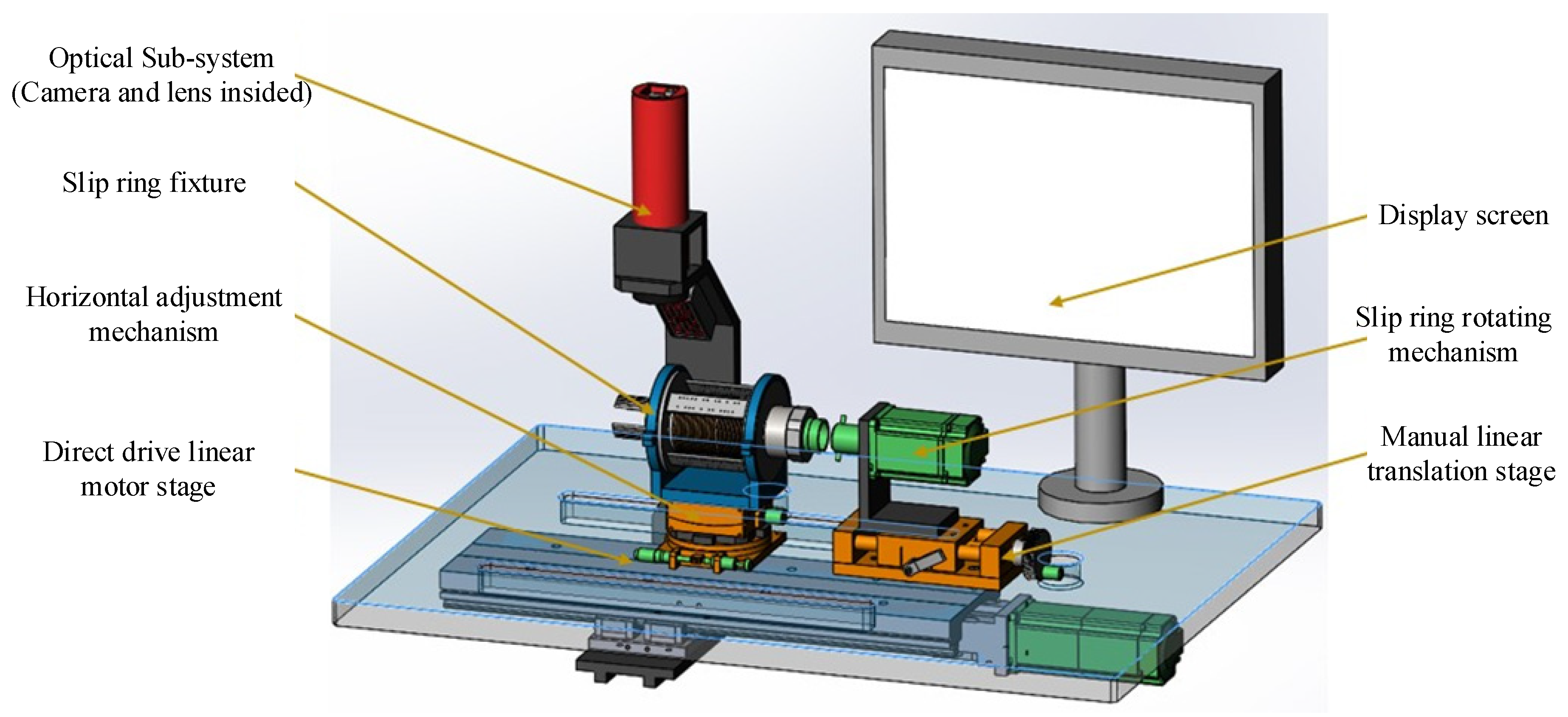
As illustrated in Figure 2, the vision-aided brush alignment assembly system for precision conductive slip rings is mainly composed of an optical and a mechanical sub-system. The optical sub-system consists of an industrial camera, a macro lens, a line laser source, as well as an infrared light source. It has two working modes depending on the different light source projected. The line laser source is used with the camera to capture the images for further extraction of the ring groove positions, and the infrared light source is used for the brush position tracking during the brush assembly process.
The mechanical sub-system includes a slip ring fixture, a horizontal adjustment mechanism, slip ring rotating mechanism, a direct drive linear motor stage and a manual linear translation stage. When measuring, the precision conductive slip ring is first fixed by two ring clamps on the fixture. Then the two axes of the horizontal adjustment mechanism are adjusted until the axis of the slip ring is nearly parallel to the translating direction of the direct drive linear motor stage. By driving the manual linear translation stage forward, the slip ring rotating mechanism is connected to the rotary shaft of the slip ring. The optical sub-system is mounted on the direct drive linear motor stage under the worktable and can measure all the ring grooves along the translation range. During the measurement process, the optical sub-system obtains images from the top for analysis, and uses the rotating mechanism to measure four quadrant positions of the ring groove. The positions of the ring grooves and the brush pose deviation can be calculated and showed on the display screen simultaneously, thus can give adjustment guidance to assist the operators to assemble the brushes more quickly and precisely.
2.2. System Measurement Procedures
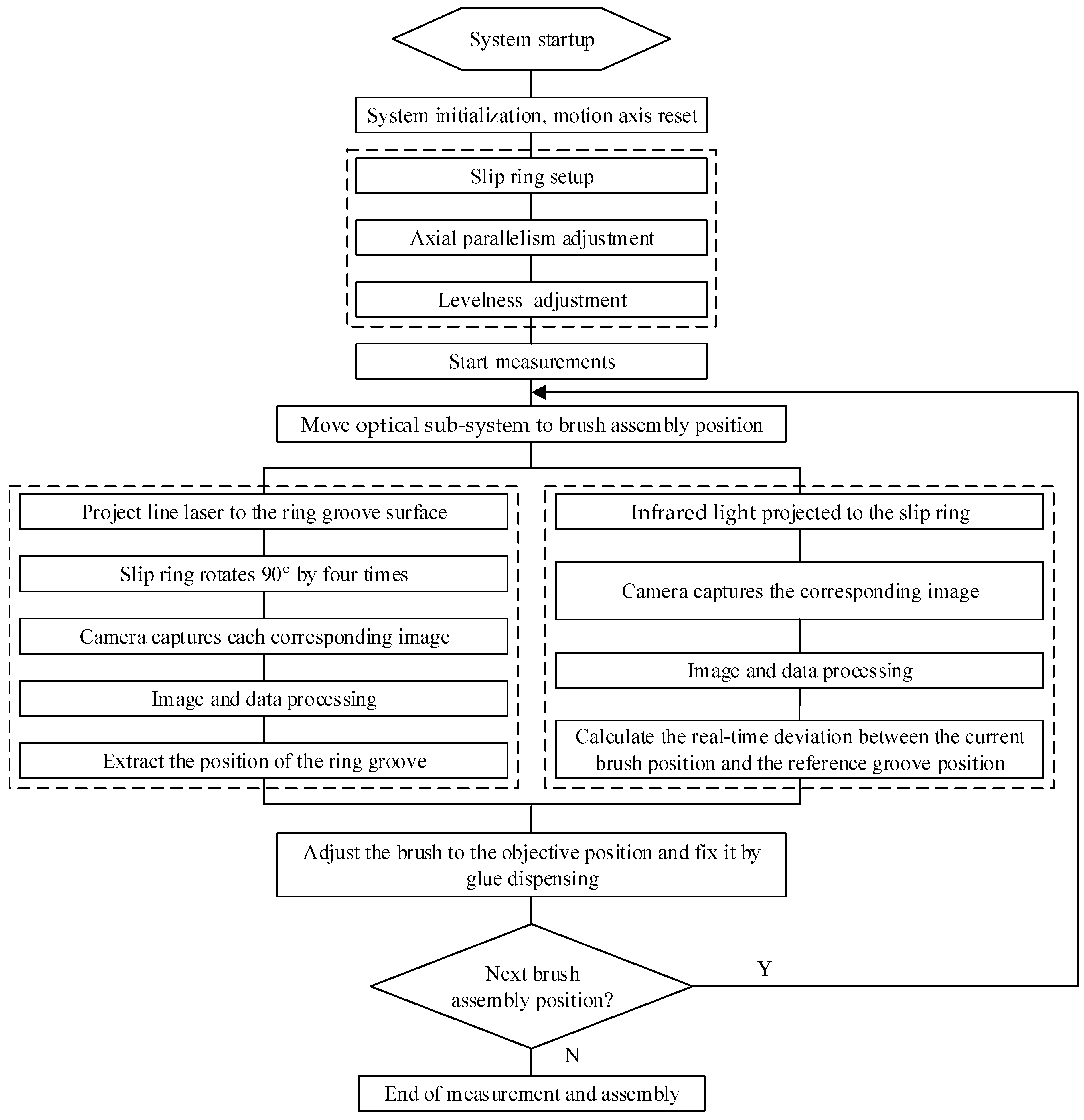
The measurement procedures of groove position and brush position for the vision-aided brush alignment assembly system is described in Figure 3. First of all, the system is started and its motion axes are reset to accomplish the system initialization. Before the actual measurement, the conductive slip ring is fixed and adjusts its axial parallelism and levelness to make its axis parallel to the translating direction of the linear motor stage. The system measures the groove and brush positions one by one in a sequential way along the translating direction of the optical sub-system.
During one measurement, the optical sub-system mounted on the direct drive linear motor stage is moved to the theorical position of the specific conductive ring. In order to measure the groove positions, the line laser is projected onto the ring groove surface, and the slip ring is rotated by 90° four times and the camera captures each corresponding image, respectively. The image and data processing are then carried out to extract the mean value of the ring groove position as the target position of the brush alignment assembly.
In order to track the relative brush position with respect to the groove, the infrared light is projected onto the slip ring from the side. Then, the camera captures the corresponding brush image, and image and data processing are adopted to calculate the deviation between the current brush position and the reference groove position. Based on this, the brush can be adjusted to its proper position and then is fixed by glue dispensing to finish the brush assembly at its current position. The optical sub-system then can be moved to the other groove positions to complete the entire brush assembly.
3. Vision Measurement Methods
3.1. Vision Measurement of Groove Position
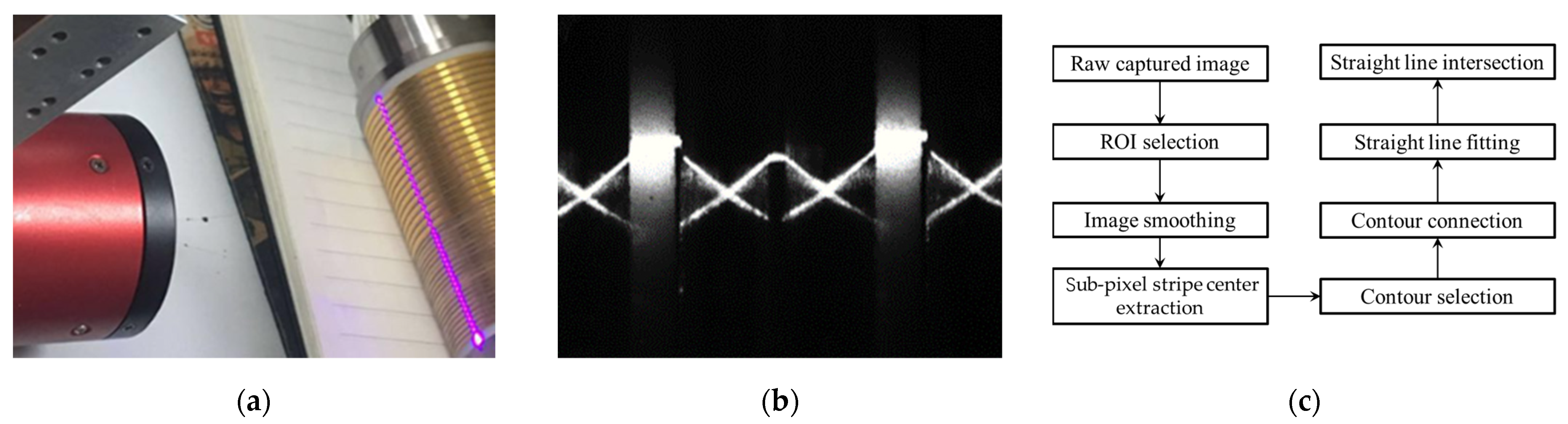
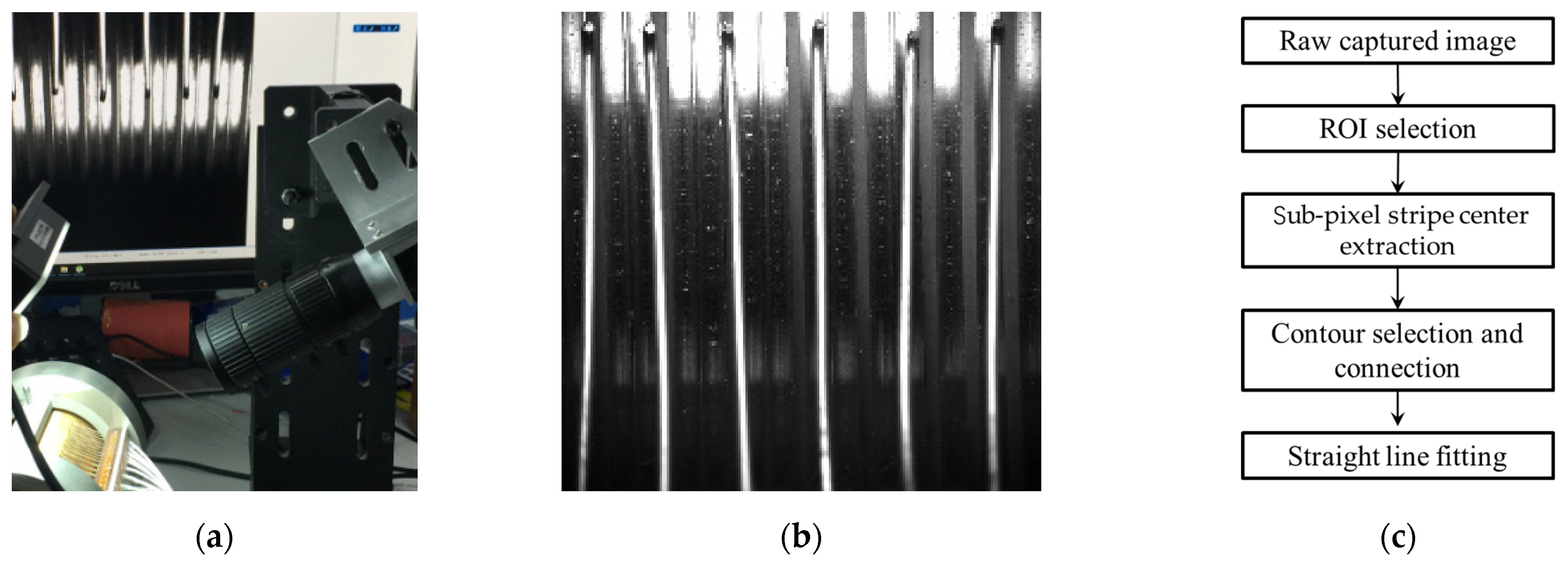
As represented in Figure 4a, the line laser is projected onto the surface of the slip ring groove, and the camera captures the corresponding image. Due to the reflection of the smooth metal surface of the groove side walls, two beams of crossed laser lines are formed in the captured image, as shown in Figure 4b, and the intersection of the formed two crossed laser lines can be considered as the bottom position of the slip ring groove. As shown in Figure 4c, through the processes of region of interest setting, image smoothing, sub-pixel stripe center extraction, contour selection and connection, straight line fitting and intersection, the intersection of the crossed laser lines can be obtained to accomplish the accurate measurement of the slip ring groove.
3.1.1. Setting of the Region of Interest
When the line laser is projected onto the surface of the slip ring groove, the captured image, as illustrated in Figure 4b, has a large resolution and covers a larger field of view than is necessary to determine the current groove position. Therefore, it is necessary to set a region of interest in the groove image to improve the image processing efficiency. In addition, the system measures the groove and brush positions of each conductive ring individually. For each measurement, only the conductive ring on the image, which the camera is directly pointing to, is considered for further processing. Normally it is the most central groove in the image. Thus, the region of interest can be set to the image’s central area only containing the most central groove. Furthermore, this region of interest is a fixed area for all of the measurements in the developed system.
In order to set the region of interest, an initial region of interest is obtained by thresholding the gray value in the slip ring groove image, then the image dilation process is applied to retain the valid pixels which define the proper region of interest.
The purpose of image thresholding is to filter the pixels within the specified gray value range in the image into the region to obtain the valid pixels, which can be defined as the following mathematical expression [14]:
where is the minimum gray value, and is the maximum gray value.
After image thresholding, it is necessary to extract the connected component based on conditional dilation to obtain the laser stripe information in the region of interest. Dilation operation can be simply understood as the “coarsening” operation of the image, which is a collective operation expressed by operator , and its mathematical expression is described as follows:
where the region is the mirror region of the region with regard to the origin , and the region is the translation region of the region with regard to the vector .
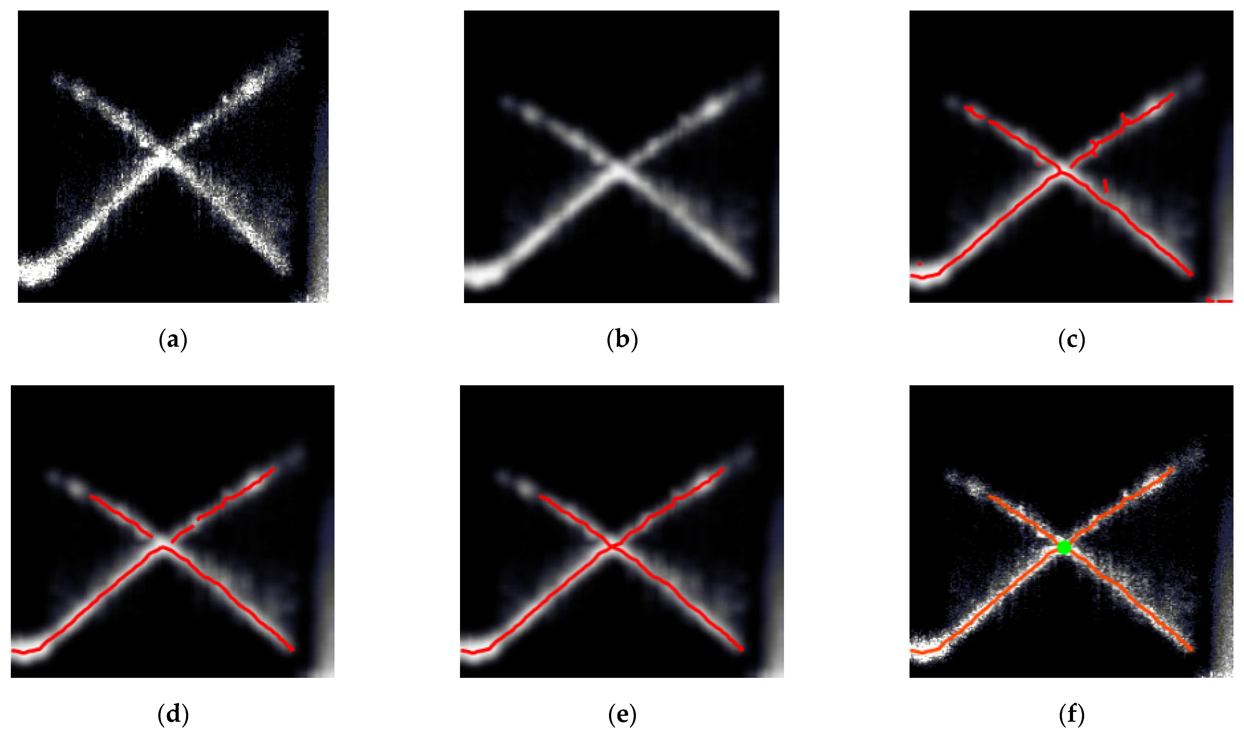
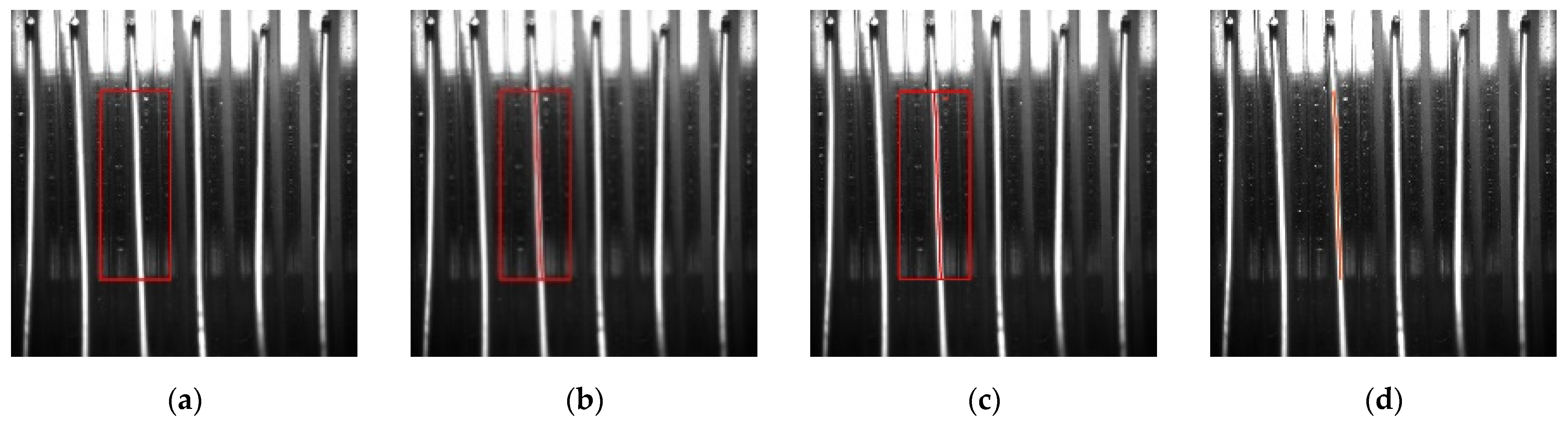
Figure 5a is an example of the obtained region of interest for one captured image. It’s used is for better illustration of the image processing procedures.
3.1.2. Image Smoothing
The image smoothing preprocessing can be realized by convoluting the above region of interest with the Gaussian filter, as shown in Figure 5b. The two-dimensional Gaussian filter is applied to smooth the region of interest, and its expression is defined as the following formula [15]:
where represents the convolution operator, the axis is along the direction, and the axis is perpendicular to the direction.
3.1.3. Stripe Center Sub-Pixel Extraction
As shown in Figure 5c, Steger’s method, based on the Hessian matrix, is used to extract the sub-pixel laser stripe center [16]. Specifically, the normal direction of the stripe is calculated based on the Hessian matrix, and the sub-pixel position of the stripe center is solved by Taylor expansion in its normal direction. Assuming that the coordinate of one point is , the Hessian matrix expression of the above point is described as follows:
where represents the two-dimensional Gaussian convolution function, is an image matrix with the coordinate point as the center and the size equal to the two-dimensional Gaussian convolution function. After the Hessian matrix is obtained, the normal direction of the stripe is the direction where the absolute value of the second-order directional derivative of the above image matrix takes the maximum value, which can be determined by calculating the eigenvectors and eigenvalues of the Hessian matrix [17].
It is assumed that the coordinate point is the reference point and the unit vector is the normal direction of the stripe. Derived from the analysis, the sub-pixel coordinate of the stripe center is defined as follows.
where is expressed as the following formula.
and are the convolution results between the first-order derivative of the above two-dimensional Gaussian convolution function and the above image matrix, which are described as follows, respectively.
3.1.4. Contour Selection and Connection
According to the characteristics of the contour area and length, the previously extracted sub-pixel contours are selected, as shown in Figure 5d,e. Using the similarity between edge points and adjacent edge points (the difference between gradient and direction is less than the threshold), the adjacent contour lines are connected to obtain the laser stripe center information.
3.1.5. Straight Line Fitting and Intersection
The weighted least square method is adopted to fit the above stripe center. The least square method takes the minimum residual sum of squares as the linear fitting criterion. The weighted least square method introduces a weight coefficient before each residual to balance the proportion of each item in the sum of squares, whose mathematical expression is shown in the following formula [18]:
Based on the single-optical line laser principle, the laser is projected onto the surface of the slip ring groove, and the camera captures the corresponding image. As illustrated in Figure 5f, the intersection of two crossed line lasers is obtained to ensure the accurate position measurement of the slip ring groove via the region of interest setting, image smoothing, sub-pixel stripe center extraction, contour selection and connection, straight line fitting and intersection.
3.2. Vision Tracking of the Brush Position
Due to the V-shaped circumferential groove characteristics on the smooth metal side wall surface of the slip ring, if the forward projection lighting mode is adopted during projection, the identification of the ring groove is not accurate enough in the image domain, which brings large errors in the extraction of the ring groove. Therefore, the groove position was set as the brush wire assembly benchmark. During the brush alignment, as shown in Figure 6a, the bar light is projected to the slip ring from the side and the camera captures the corresponding brush image, as shown in Figure 6b, the brush is imaged as the highlighted identifiable area in the image domain, from which the position deviation can be accurately extracted.
Using the side lighting method, the surface curvature of the ring groove and the brush wire is different, and the corresponding light reflection results are different as well, resulting in different gray values in the image. As shown in Figure 6c and Figure 7, by setting the region of interest, sub-pixel brush center extraction, contour connection, and straight-line fitting, the actual brush position, as well as its angle, can be obtained accurately.
4. Calibration of the Optical Imaging System
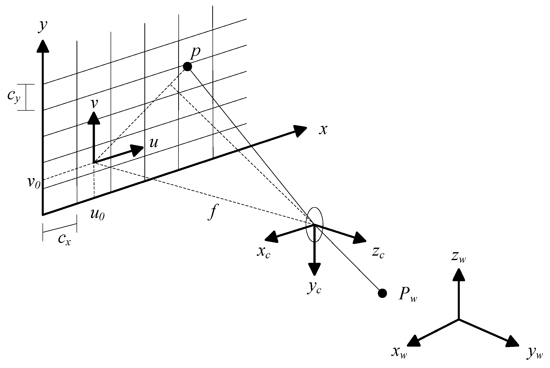
As presented in Figure 8, the calibration of the optical imaging system is to establish the coordinate conversion relationship from the spatial point represented in the world coordinate system to the corresponding projection point represented in the pixel coordinate system . There are enough known spatial points in the world coordinate system as well as their corresponding projection points in the pixel coordinate system to establish the coordinate conversion relationship, and further to calculate the internal and external parameters of the camera [19].
The calibration model of the optical imaging system is based on the pinhole model, and its mathematical expression is represented as follows [20]:
where is the spatial point represented in the world coordinate system; and represent the rotation matrix and translation vector from the world coordinate system to the camera coordinate system, respectively; is the corresponding Z-axis coordinate represented in the camera coordinate system; represents the focal length; is the origin of the image coordinate system represented in the pixel coordinate system; is the corresponding projection point represented in the pixel coordinate system; and are the numbers of pixels per unit distance represented in the image coordinate system, , .
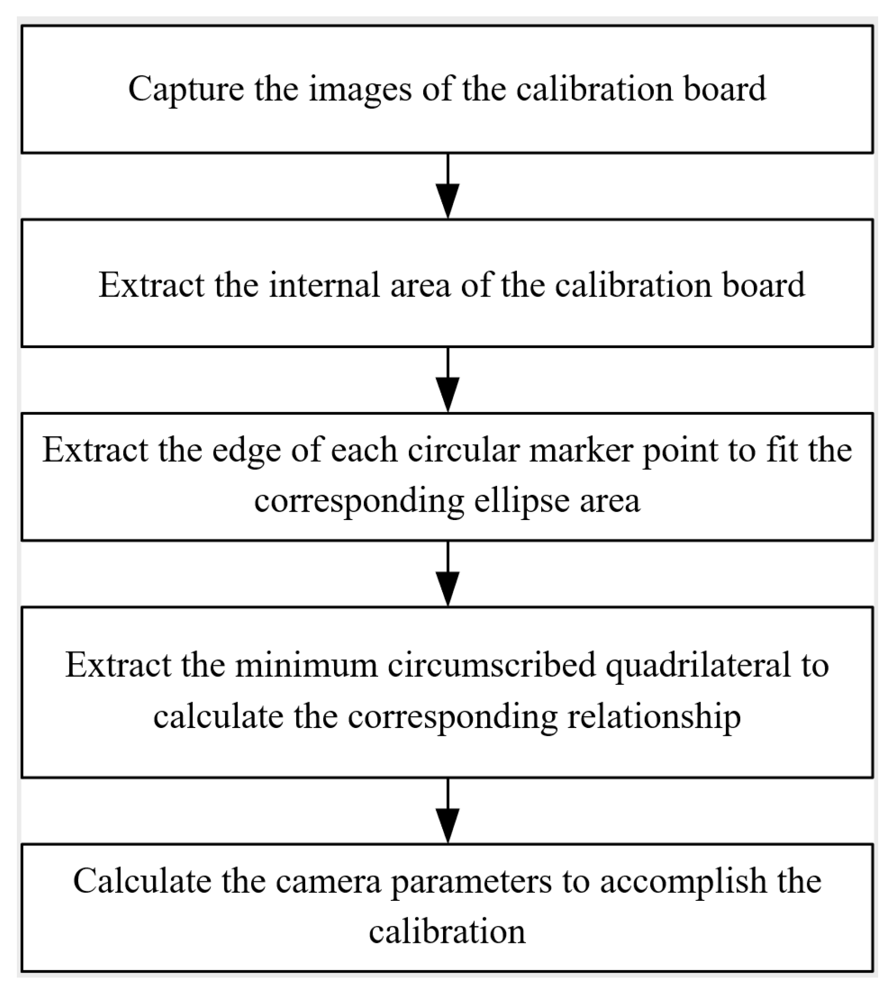
As shown in Figure 9, the calibration of the optical imaging system can be completed by using a high-precision circular calibration board. Firstly, capture the images of the circular calibration board; Secondly, extract the internal area of the calibration board by image segmentation; Thirdly, extract the edge of each circular marker point of the calibration board to fit the corresponding ellipse area; Fourthly, extract the minimum circumscribed quadrilateral belonging to each ellipse area and calculate the corresponding relationship between each circular marker point and each projection point; Finally, calculate the camera parameters to accomplish the calibration.
5. System Development and Experiments
5.1. System Development
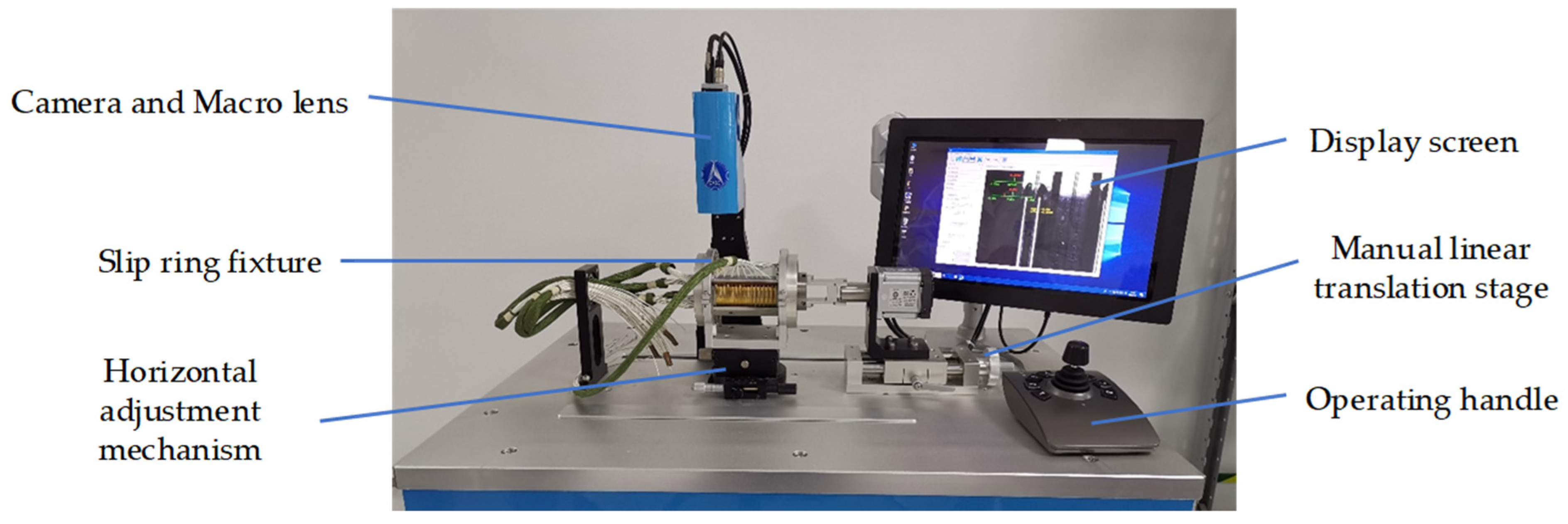
Based on the above research, a vision-aided brush alignment assembly system was developed as shown in Figure 10. The industrial camera is Balser acA1600-60gm with 2048 pixels × 1088 pixels resolution and 60 fps frame rate. The macro lens is Computar MLM-3X-MP zoom lens with the focal length of 90 mm. The field of view of the optical sub-system is 8 mm × 6 mm at 120 mm working distance. The laser is Thorlabs’ DL3148-025 type red laser diode and LJ1227L2 type plano-convex cylindrical mirror with a laser wavelength of 635 nm. The direct drive linear motor stage adopts the Misumi high-precision displacement platform KUH1505-520-100-A1 model, its translation range is 320 mm, and the positioning accuracy is 0.01 mm.
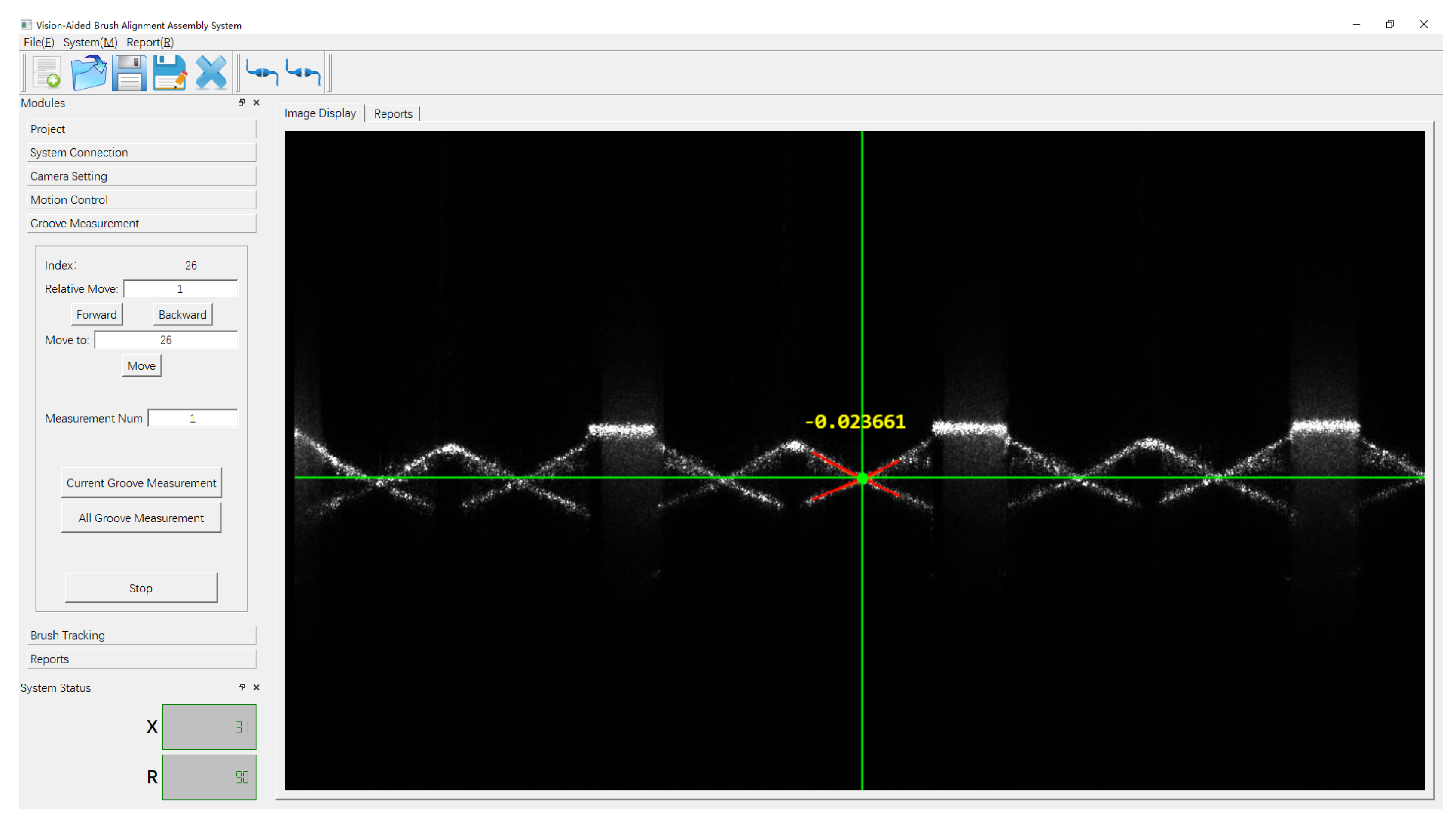
The developed software is shown in Figure 11. It includes the project management module, hardware communication module, parameter calibration, visual measurement module, data processing module and human–computer interaction module. The software interface design and development are realized using Visual Studio and QT, and the core image processing algorithm development is based on MVTec Halcon.
Based on the development of hardware and software of the vision-aided brush alignment assembly system, the measured data is intuitively fed back in real time to support the quantitative evaluation of the alignment status between the brush position and the groove position, and can provide the in-situ assembly guidance to the operators, which improves the assembly accuracy and efficiency during the brush assembly process.
5.2. System Calibration
In order to accurately obtain the camera parameters, calibration needs to be carried out based on multiple board images from different perspectives. As seen in Figure 12, a high-precision circular calibration board is placed on the worktable, and the placement position and pose of the calibration board is adjusted to obtain the calibration results. The circular calibration board (accuracy of 0.1 µm) has an array of 7 × 7 circular marker points and the diameter of each circular marker point is 1.5 mm. After capturing enough calibration photos for calibration, the calibrated pixel conversion ratio is 0.00685 mm/pixel.
5.3. System Measurement
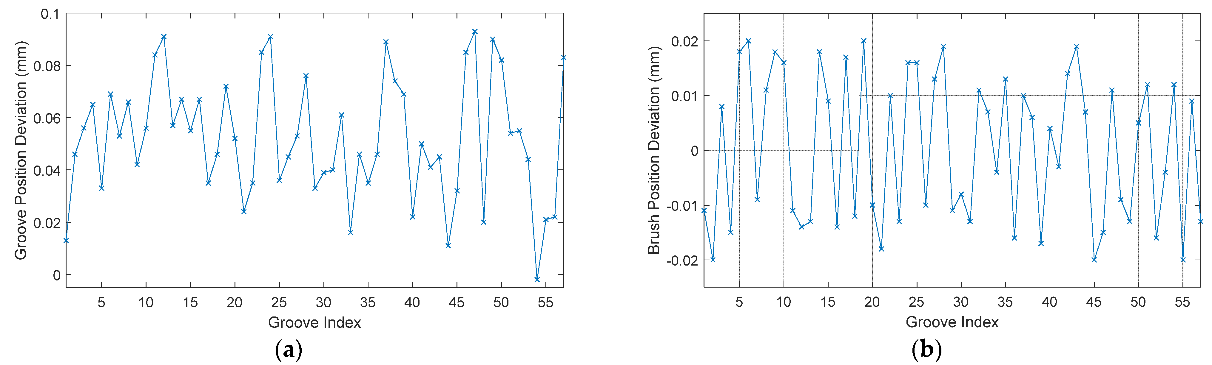
A SADA precision conductive slip ring is used to evaluate the performance of the developed vision-aided brush alignment assembly system. It has 57 conductive rings, each of which has a V-shaped slip groove. The groove positions are measured using the developed system and the groove position deviation with respect to their designed position value is shown in Figure 13a. The groove position deviation is 0.0520 ± 0.0234 mm, which, in some sense, indicates that the groove position error due to the groove machining process cannot be neglected. The brush alignment assembly is further carried out and the final brush position deviation with respect to the measured groove positions is obtained, as shown in Figure 13b. It shows that with the developed system, the brush alignment assembly accuracy can be controlled within ±0.02 mm. Through the field experiment, eight conductive rings are aligned precisely between the brush and the ring groove per minute, which proves the high alignment efficiency of the system.
6. Conclusions
In this paper, a vison-aided brush alignment assembly method is proposed based on 2D image measurement and image processing technologies. By analysis and processing of the ring groove and brush images, the alignment status of the ring groove and brush center is extracted and quantitatively evaluated. The quantitative feedback of the measured data can realize the in-situ guidance of the assembly operation and improve the alignment accuracy of the ring groove and brush in the assembly process. The measurement hardware system is developed via the design of system optical path, mechanical structure and the selection of core components. The measurement software system is developed with the modules of image processing, precision control, measurement process, image feature extraction and data visualization. The experiments verified the performance of the developed vision-aided brush alignment assembly system.
Author Contributions
Conceptualization, X.C., J.X. and X.Y.; methodology, X.C. and Y.W.; software, X.C. and Y.S.; validation, Y.W. and Y.S.; data curation, X.Y.; writing—original draft preparation, Y.W. and Y.S.; writing—review and editing, X.C. and X.Y.; visualization, X.C., C.Y. All authors have read and agreed to the published version of the manuscript.
Funding
This research was funded by National Natural Science Foundation of China (52175478), Defense Industrial Technology Development Program (JCKY2020203B039), and the Science and Technology Commission of Shanghai Municipality (21511102602).
Institutional Review Board Statement
Not applicable.
Informed Consent Statement
Not applicable.
Data Availability Statement
Not applicable.
Conflicts of Interest
The authors declare no conflict of interest.
References
- Lu, J.M.; Xing, L.H.; Li, Y.E.; Ge, F.J. The key technology and developing trend of the precision conductive slip-ring. Navig. Control 2015, 14, 20–26. [Google Scholar]
- Avino, F.; Gaffinet, B.; Bommottet, D.; Howling, A.; Furno, I. Slip ring test assembly with increased breakdown voltage limit for high-voltage bus satellites. IEEE Aerosp. Electron. Syst. Mag. 2020, 35, 32–36. [Google Scholar] [CrossRef]
- Ayub, M.A.; Mohamed, A.B.; Esa, A.H. In-line inspection of roundness using machine vision. Procedia Technol. 2014, 15, 807–816. [Google Scholar] [CrossRef] [Green Version]
- Li, X.; Wang, L.; Cai, N. Machine-vision-based surface finish inspection for cutting tool replacement in production. Int. J. Prod. Res. 2004, 11, 2279–2287. [Google Scholar] [CrossRef]
- Connolly, C. Optical inspection tools for the automotive industry. Sens. Rev. 2004, 24, 347–352. [Google Scholar] [CrossRef]
- Manish, R.; Venkatesh, A.; Ashok, S. Machine vision based image processing techniques for surface finish and defect inspection in a grinding process. Mater. Today Proc. 2018, 5, 12792–12802. [Google Scholar] [CrossRef]
- Chauhan, V.; Surgenor, B. Fault detection and classification in automated assembly machines using machine vision. Int. J. Adv. Manuf. Technol. 2014, 90, 2491–2512. [Google Scholar] [CrossRef] [Green Version]
- Shen, H.; Li, S.X.; Gu, D.Y.; Chang, H.X. Bearing defect inspection based on machine vision. Measurement 2012, 45, 719–733. [Google Scholar] [CrossRef]
- Jiang, P.; Yang, X.; Xi, J.T. Technology research and system development of on-machine measurement for slip ring based on machine vision. Modul. Mach. Tool Autom. Manuf. Tech. 2017, 3, 74–76+79. [Google Scholar]
- Dong, F.K.; Zheng, Z.Z.; Yuan, S.F.; Li, F.; Shi, Y.K. Research and development of micro-slot position detection system for conductive slip surface based on machine vision. Manuf. Technol. Mach. Tool 2018, 4, 126–130. [Google Scholar]
- Guo, W.T.; Wang, Y.L.; Lian, Z.X.; Zhang, Q.; Li, L.; Wang, M.Y. Research on detection method of precision assembly position based on line structured light. Laser Infrared 2021, 51, 720–726. [Google Scholar]
- Li, J.Y.; Li, J.; Wang, X.P.; Tian, G.Q.; Fan, J.F. Machine vision-based method for measuring and controlling the angle of conductive slip ring brushes. Micromachines 2022, 13, 447. [Google Scholar] [CrossRef] [PubMed]
- Wang, X.P. Research on Angle Forming and Pressure Detection Technology of Conductive Slip Ring Brush Wire; Changchun University of Science and Technology: Changchun, China, 2021. [Google Scholar]
- Zhao, D.; Wu, Z.Q.; Yang, H.; Zhang, S.M.; Xi, J.T. Extracting characteristic size of crankshaft groove automatically based on shadow casting. Opto-Electron. Eng. 2012, 39, 63–70. [Google Scholar]
- Geusebroek, J.M.; Smeulders, A.W.M.; Weijer, J.V.D. Fast anisotropic gauss filtering. IEEE Trans. Image Process. 2003, 12, 938–943. [Google Scholar] [CrossRef] [PubMed] [Green Version]
- Steger, C. An unbiased detector of curvilinear structures. IEEE Trans. Pattern Anal. Mach. Intell. 1998, 20, 113–125. [Google Scholar] [CrossRef] [Green Version]
- Xu, G.; Sun, L.N.; Li, X.T.; Su, J.; Hao, Z.B.; Lu, X. Adaptable center detection of a laser line with a normalization approach using hessian-matrix eigenvalues. J. Opt. Soc. Korea 2014, 18, 317–329. [Google Scholar] [CrossRef] [Green Version]
- Min, D.B.; Choi, S.; Lu, J.B.; Ham, B.; Sohn, K.; Do, M.N. Fast global image smoothing based on weighted least squares. IEEE Trans. Image Process. 2014, 23, 5638–5653. [Google Scholar] [CrossRef] [PubMed]
- Zhao, D. Research of the Automatic and Precision Measurement of Crankshaft Groove in Automobile Engine Based on Shadow Casting; Shanghai Jiao Tong University: Shanghai, China, 2012. [Google Scholar]
- Wang, Y.K.; Ye, F.; Li, J.; Chen, X.B.; Xi, J.T.; Xu, X.J. Underwater fuel assembly deformation measurement with multisensor dual-line structured light. Appl. Opt. 2021, 60, 9624–9633. [Google Scholar] [CrossRef] [PubMed]
Figure 1.
Conductive slip ring: (a) SADA slip ring; (b) Enlarged view of (a); (c) Design model of slip ring.
Figure 1.
Conductive slip ring: (a) SADA slip ring; (b) Enlarged view of (a); (c) Design model of slip ring.

Figure 2.
Schematic diagram of the vision-aided brush alignment assembly system.

Figure 3.
Vision-aided brush alignment assembly procedures.

Figure 4.
Measurement of the slip ring groove position: (a) Line laser projected onto the groove surface; (b) Captured laser line image on the groove side walls; (c) Flow diagram of the image processing to measure the groove position.
Figure 4.
Measurement of the slip ring groove position: (a) Line laser projected onto the groove surface; (b) Captured laser line image on the groove side walls; (c) Flow diagram of the image processing to measure the groove position.

Figure 5.
Image processing for the extraction of the groove position: (a) Region of interest selection; (b) Image smoothing; (c) Sub-pixel stripe center extraction; (d) Contour selection; (e) Contour connection; (f) Straight line fitting and intersection.
Figure 5.
Image processing for the extraction of the groove position: (a) Region of interest selection; (b) Image smoothing; (c) Sub-pixel stripe center extraction; (d) Contour selection; (e) Contour connection; (f) Straight line fitting and intersection.

Figure 6.
Vision tracking of brush position: (a) Light projection; (b) Brush image; (c) Flow diagram of the image processing to track the brushes.
Figure 6.
Vision tracking of brush position: (a) Light projection; (b) Brush image; (c) Flow diagram of the image processing to track the brushes.

Figure 7.
Image processing for vision tracking of brush position: (a) Region of interest; (b) Sub-pixel stripe center extraction; (c) Contour selection and connection; (d) Straight line fitting.
Figure 7.
Image processing for vision tracking of brush position: (a) Region of interest; (b) Sub-pixel stripe center extraction; (c) Contour selection and connection; (d) Straight line fitting.

Figure 8.
Calibration projection relation of optical imaging system.

Figure 9.
The calibration precedes of the optical imaging system.

Figure 10.
Developed vision-aided brush alignment assembly system.

Figure 11.
Software developed for vision-aided brush alignment assembly system.

Figure 12.
Calibration of optical imaging system.

Figure 13.
System measurement results: (a) Slip groove position error; (b) Brush assembly error.

Publisher’s Note: MDPI stays neutral with regard to jurisdictional claims in published maps and institutional affiliations. |
© 2022 by the authors. Licensee MDPI, Basel, Switzerland. This article is an open access article distributed under the terms and conditions of the Creative Commons Attribution (CC BY) license (https://creativecommons.org/licenses/by/4.0/).
Share and Cite
MDPI and ACS Style
Chen, X.; Wang, Y.; Sheng, Y.; Yu, C.; Yang, X.; Xi, J. Vision-Aided Brush Alignment Assembly System for Precision Conductive Slip Rings. Machines 2022, 10, 393. https://0-doi-org.brum.beds.ac.uk/10.3390/machines10050393
AMA Style
Chen X, Wang Y, Sheng Y, Yu C, Yang X, Xi J. Vision-Aided Brush Alignment Assembly System for Precision Conductive Slip Rings. Machines. 2022; 10(5):393. https://0-doi-org.brum.beds.ac.uk/10.3390/machines10050393
Chicago/Turabian StyleChen, Xiaobo, Yukun Wang, Ying Sheng, Chengyi Yu, Xiao Yang, and Juntong Xi. 2022. "Vision-Aided Brush Alignment Assembly System for Precision Conductive Slip Rings" Machines 10, no. 5: 393. https://0-doi-org.brum.beds.ac.uk/10.3390/machines10050393
Note that from the first issue of 2016, this journal uses article numbers instead of page numbers. See further details here.