
Conjugate Heat Transfer Simulation of Overall Cooling Performance for Cratered Film Cooling Holes


1
Tianjin Key Laboratory for Advanced Mechatronic System Design and Intelligent Control, School of Mechanical Engineering, Tianjin University of Technology, Tianjin 300384, China
2
National Demonstration Center for Experimental Mechanical and Electrical Engineering Education, Tianjin University of Technology, Tianjin 300384, China
3
School of Energy and Power Engineering, Shandong University, Jinan 250061, China
*
Author to whom correspondence should be addressed.
Machines 2022, 10(5), 395; https://0-doi-org.brum.beds.ac.uk/10.3390/machines10050395
Submission received: 18 April 2022
/
Revised: 16 May 2022
/
Accepted: 17 May 2022
/
Published: 19 May 2022
(This article belongs to the Section Electromechanical Energy Conversion Systems)
Abstract
:Film cooling is widely applied as an effective way to maintain the turbine blade temperature at an acceptable level. The present paper investigates the overall cooling effectiveness and flow structure by performing conjugate heat transfer simulations for the flat-plate baseline cylindrical and three cratered film-cooling holes. The flow and heat transfer in the fluid domain is obtained using the Shear Stress Transport turbulence model, and the solid conductivity is considered by solving the Laplace equation. Four blowing ratios ranging from 0.5 to 2.0 are studied. The numerical results show that the concentric elliptic cratered hole yields a slightly higher overall cooling effectiveness than the baseline cylindrical hole, but the two contoured cratered holes exhibit great improvements due to the generation of the anti-kidney-shaped vortex pair. The area-averaged overall cooling effectiveness has improved by 5.58–65.30% for the contoured cratered hole. The variation of Biot number results in small change in the area-averaged overall cooling effectiveness. However, the area-averaged overall cooling effectiveness uniformity coefficient depends on the Biot number.
1. Introduction
The turbine inlet temperature increases from 700 °C for the original aircraft engine to nearly 1700 °C for the modern aircraft engine and heavy-duty land-based gas turbine. Nowadays, despite advanced single crystal nickel-based superalloy and thermal barrier coating being adopted, there is still a gap between the maximum allowable temperature of the material and the operating temperature. Hence, the cooling technology is essential to reduce the temperature of the turbine blade below the upper-temperature limit for safety.
One of the most effective ways is film-cooling technology, which was first proposed by Goldstein [1] in the 1970s. The cooling air bleeding from the compressor flows through discrete holes to form a thin protective layer over the blade surface, isolating the mainstream hot gas. The cylindrical hole is the most commonly used type for film cooling. As reported in [2,3,4], the cylindrical hole has a remarkably reduced cooling effectiveness when the blowing ratio is larger than 0.5. Hence, a great effort has been made for modifications based on the cylindrical hole to improve the cooling effectiveness. The fan-shaped hole with an expanded exit has been proven as a great outstanding contribution with practice. Goldstein et al. [5] pointed out that the enlarged area at the fan-shaped hole exit can lower the coolant momentum and enhance the lateral coolant coverage. Gritsch et al. [6] symmetrically studied the geometrical sensitivity analysis for the fan-shaped hole with sixteen variants and found limited sensitivity in the laterally averaged cooling effectiveness. Lee and Kim [7] optimized the laid-back fan-shaped hole and improved the area-averaged cooling effectiveness with an enhancement of 28% compared with the reference geometry.
However, the complicated geometry of the fan-shaped hole gives high-cost manufacturing. Hence, in recent years, novel configurations with high cooling performance but low-cost manufacturing have been proposed. The specialty of this kind of novel scheme, including the trenched hole and the cratered hole, is assisted by thermal barrier coating with modifications near the hole exit surface, as reported in [8]. Comparatively, the discrete cratered hole could relieve the structural integrity weakening of the successive trenched hole, as discussed in [9]. The experimental data in [10] showed that the cratered hole gives a slightly higher adiabatic cooling effectiveness but a substantial increase in heat transfer enhancement. Lu et al. [10] also deduced that the cratered hole might perform better at lower blowing ratios than the cylindrical hole. Khalatov et al. [11] performed a comparison work for cratered holes with hemispherical, cylindrical, and triangular dimples. It is found that the adiabatic cooling effectiveness depends on the specific crater shape, and the triangular cratered hole gives the best performance. The numerical research in [12] showed that the triangular created with a convexly-curved leading-edge performs smaller improvements on the laterally averaged adiabatic cooling effectiveness than a straight-line leading-edge. A new design of a contoured cratered hole with a V-shaped protrusion was proposed in [13] to improve the adiabatic cooling effectiveness. Their numerical results showed that adiabatic cooling effectiveness is improved by 200–300%, whereas the heat transfer coefficient increases by 50–80% compared with the cylindrical hole. The mechanism of generation of the anti-Counter rotating vortex pair (CRVP) and attenuation of CRVP was revealed by Kalghatgi and Acharya [14] for this cratered hole. An et al. [15] proposed a contoured cratered hole with a similar shape but larger streamwise and lateral expansions and validated its superiority by performing the experimental measurement. As reported in [13,16], the crater depth affected the adiabatic cooling effectiveness of the cratered hole significantly. Bai et al. [17] performed the sensitivity analysis of the geometrical parameters for the contoured crater and obtained the optimal crater shapes at two blowing ratios of 0.5 and 1.5.
Nevertheless, the heat conductivity effect was not considered in the research works mentioned above for film-cooling, and the adiabatic cooling effectiveness was taken as the evaluation target. As revealed in [18,19,20,21], the conjugate heat transfer model predicted a significant difference in the temperature distribution compared with the adiabatic model for the film-cooling holes investigated. Moreover, the other difference is the additional heating up of the cooling jet for the conjugate heat transfer model. Hence, the conjugate heat transfer model should be considered for the film-cooling holes, and the overall cooling effectiveness is taken as the cooling performance evaluation. Kusterer et al. [22], Alizadeh et al. [23], Wang et al. [24], and Fu et al. [25] performed the conjugate heat transfer simulations to improve designs of the film-cooling blade, flat-plate film cooling with trenched holes, or the combined film-impingement cooling configuration. Bryant and Rutledge [26] proposed a new technique to analyze the relative contribution of internal cooling, external cooling, and convection on overall cooling effectiveness through the film cooling hole. The influence of the Biot number, denoting the ratio of convection heat transfer resistance to heat conductivity resistance, on the overall cooling effectiveness, was underlined for the cylindrical hole [27], the fan-shaped hole [26], and the double-wall structure with cylindrical film cooling and pins [28].
The literature review concluded that no study is relevant to the cratered film cooling holes considering the conjugate heat transfer. The influence of the Biot number on the overall cooling effectiveness of the cratered hole is not well understood. Hence, the present paper investigates the overall cooling effectiveness and flow structure of one concentric and two contoured cratered holes compared to the cylindrical hole as the benchmark. Besides, the overall cooling effectiveness of the contoured holes is analyzed with variant Biot number by changing the solid heat conductivity.
2. Physical Model and Numerical Method
2.1. Physical Model
The present study investigates four different film cooling holes, shown in Figure 1, including the cylindrical (CYL) hole, a circular cratered (CIR_CRA) hole, and two contoured cratered holes with alternative dimensions. The CYL hole has a diameter of D = 1 mm and an inclination angle of 30° relative to the streamwise direction (axis X). The length along the hole axis of the CYL hole is 6D, which means the thickness of the solid plate equals 3D. For the cratered holes, the location of the cylindrical section is kept the same as the cylindrical hole. The total thickness of the cylindrical section and the crater section is also 3D. The CIR_CRA hole has a crater depth of 0.5D and an outer profile with margins of 0.5D in the streamwise direction and lateral direction (axis Y). The contoured craters have more complicated shapes with streamwise and lateral expansions than the CIR_CRA hole. The leading edge of the contoured crater consists of a middle convex protrusion and two sections of straight lines aside. For the CRA1 hole, the leading edge is located at a distance of 1.0D downstream from the cylindrical hole exit. The total width of the leading edge for the CRA1 hole is 2.0D. The CRA2 hole is obtained from the optimization work in [17] for the optimal crater at a blowing ratio of 1.5. The CRA hole has a leading edge with a total width of 2.8D and a larger distance of 2.392D from the cylindrical hole exit. The crater depths are 0.5D for the CRA1 hole and 0.83D for the CRA2 hole. The convex protrusion’s streamwise length and lateral width are 0.5D and 1.0D for the CRA1 hole, and 1.572D and 1.226D for the CRA2 hole, respectively. The CRA2 hole with a deeper and larger crater is supposed to exhibit a higher cooling performance than the CRA1 hole.
The physical model of the flat-plated film-cooling is illustrated in Figure 2, consisting of the fluid and solid domains. The fluid domain includes the mainstream passage, the coolant feeding channel, and the connecting film-cooling holes. The hot air in the mainstream passage and the coolant in the coolant feeding channel both flow along the X-direction. The film-cooling holes studied all have a lateral pitch of t = 3D. The total streamwise length of the mainstream passage is 75D, with a distance ahead of the cylindrical hole exit of 25D. The mainstream passage, the flat plate, and the coolant channel have the same streamwise lengths and lateral widths. The heights of the mainstream passage and the coolant channel are 20D and 15D, respectively. The thickness of the solid flat plate is 3D. The original point is located at the hole exit of the CYL hole and is always kept the same for the other three cratered holes. The axis Z denotes the normal direction relative to the top wall surface of the flat plate.
2.2. Boundary Condition and Data Reduction
The boundary conditions are obtained from Wang et al. [24]. The hot air enters the mainstream passage with a temperature of Th = 1500 K and a velocity of Uh = 150 m/s. The static pressure at the mainstream passage outlet is fixed as 10 bar. The coolant flows into the coolant channel with a temperature of Tc = 750 K and a velocity of Uc = 75 m/s. The turbulence intensities are 10% for the hot air at the mainstream passage inlet and 5% for the coolant at the coolant channel inlet. The static pressure at the coolant channel outlet is adjusted to attain four coolant-to-mainstream blowing ratios ranging from 0.5 to 2.0. The definition of blowing ratio M is as follows:
where, ρc is the coolant density, Uhole is the averaged velocity at the cross-section of the cylindrical hole or the cylindrical part for the cratered hole, ρh is the density of the hot air.
The flat plate is made of the nickel-based alloy with a 27.7 W/(m·K) heat conductivity. Based on the heat transfer coefficient obtained from the numerical simulation for the non-film model and the solid heat conductivity, the nominal value of the Biot number is calculated as 0.13 accordingly. In addition to the coolant directly covering the top wall surface, the heat loading of the flat plate can be directly removed by the internal convection heat transfer via the solid heat conduction. Hence, the top wall surface, the top wall surface, and the inner hole wall are all fluid-solid interfaces imposed with the non-slip condition. The sidewalls Y/D = −1.5 and 1.5 are treated as the periodic condition to simulate the flow and heat transfer of the infinite rows of cooling holes. The top surface of the mainstream passage Z/D = 20 and the coolant passage Z/D = −18 are symmetric to save the computational resource. The front and back surfaces of the flat plate are assumed as adiabatic conditions. Because a large temperature difference exists between the hot air temperature and the coolant temperature, the air’s thermophysical properties, including the heat capacity at constant pressure Cp, dynamic viscosity μ, and heat conductivity λ, are all treated as temperature-dependent variants, given as follows:
where, T is the Kelvin temperature.
For the data reduction, the local, laterally averaged, and area-averaged overall cooling effectiveness, ϕ, ϕlat, ϕarea, can be calculated as follows:
The non-dimensional temperature θ is defined as follows:
The streamwise vorticity ωX is applied to decline the vortical intensity of the kidney-shaped vortex pair or anti-kidney-shaped vortex pair, which is calculated as follows:
where, UZ is the velocity component in the Z direction, and UY is the velocity component in the Y direction.
2.3. Numerical Method Validation
The three-dimensional, steady-state conjugate heat transfer simulations are carried out to predict the flow and heat transfer for the film-cooling holes. The Naiver-Stokes equations are solved in the fluid domain. The heat conduction in the solid domain is obtained by solving the Laplace equation as follows:
where, xj is the Cartesian coordinate, j = 1, 2, 3.
The governing equations in the fluid domain are the mass, momentum, and energy conversation equations, which are listed as follows:
where Ui, Uj are the mean velocity components, ui, uj are the fluctuating velocity components, i = 1, 2, 3, p is the mean pressure, τ is the molecular stress tensor, ρ is the density, SM is the sum of the body forces, h is the fluctuating enthalpy, htot is the mean total enthalpy, T is the mean temperature, SE is the energy source.
The temperature and heat flux are conserved at the fluid-solid interface. If the root means square residuals of all variables are lower than 10−6, the convergence of the CFD simulation is achieved.
In the current study, two turbulence closures, i.e., the standard k-ε turbulence and the k-ω based Shear Stress Transport (SST) turbulence model, are tested to check CFD prediction accuracy. k is the turbulence kinetic energy, ε is the turbulence eddy dissipation, and ω is the turbulence frequency. The standard k-ε turbulence model is based on the eddy viscosity concept. Two additional transport equations of k and ε are solved. For the SST turbulence model, the modified turbulence viscosity is accounted by the transport effect of turbulent shear stress. Furthermore, it is a blending form between the standard k-ω turbulence model in the inner region of the boundary layer and the k-ε turbulence model in the outer part of the boundary layer.
The computational grids are generated using the commercial package ICEM. The structured grids around the hole are shown in Figure 3 for the CIR_CRA and CRA1 models. The grid nodes aside from the fluid-solid interface are one-to-one matched to eliminate possible data transmission errors. The computational grids in the fluid domain are refined around the fluid-solid interfaces to resolve the boundary layer. The distance between the first node and the wall in the boundary layer is 0.001D. The corresponding value of Y+ is near 1.0. The stretching ratio of grids near the surface wall is 1.2. The grid independence tests are performed, and the grid levels are selected as approximately 3 million, considering the computation resource cost and the prediction accuracy.
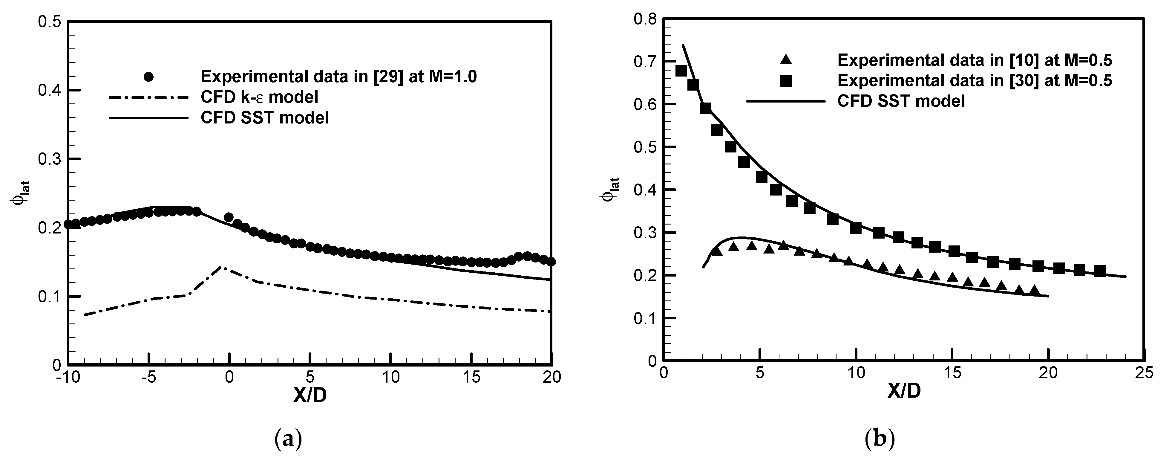
The comparisons between the CFD predicted results and the literature data of laterally averaged cooling effectiveness are shown in Figure 4. The conjugate film cooling experimental data for the CYL hole from Zhang [29] at M = 1.0 is compared with the CFD results, shown in Figure 4a. The k-ε turbulence model remarkably under-predicts the experimental data of the CYL hole at M = 0.5. Comparatively, the predicted values of the SST turbulence model agree well generally, except for the slight undervaluation in the region 10 < X/D < 20. The reason mainly lies in the disagreement in the boundary condition at the front and back surfaces of the flat plate between the simulation and the experimental measurement. Because there is no conjugate heat transfer experimental data for the cratered film-cooling holes, the adiabatic laterally averaged cooling effectiveness ηlat for the CIR_CRA hole [10] and the CRA1 hole [30] at M = 0.5 are further used for validation. It is seen that the SST turbulence model also performs a good prediction accuracy for the CIR_CRA hole and CRA1 hole. Hence, the SST turbulence model is adopted to perform conjugate heat transfer simulations for the three types of film-cooling holes.
3. Results and Discussions
3.1. Flow Structure and Temperature Field
Figure 5 shows the streamline distributions over the surface X/D = 5 at M = 0.5 for the four film-cooling holes studied. The kidney-shaped vortex pair has a counter-rotating direction marked with blue color, and the anti-kidney-shaped vortex pair exhibits an opposite sense of rotation marked by dark red color. It is seen that the kidney-shaped vortex pair, generated by the mutual effect of the ejection coolant and the mainstream flow, dominates the flow field downstream for the CYL hole. Fric and Roshko [31] revealed that the kidney-shaped vortex mainly results in the coolant departure away from the wall surface and the cooling performance degeneration, especially at high blowing ratios. Because of the relative lower momentum of the ejected coolant at M = 0.5, the kidney-shaped vortex pair is still attached to the wall surface. For the CIR_CRA hole, the flow field consists of the original kidney-shaped vortex pair in the middle and a new anti-kidney-shaped vortex pair. The interaction between the elliptic crater and the ejected coolant induces the anti-kidney-shaped vortex pair, ventilating the coolant along the lateral direction. The flow structure is remarkably different for the contoured cratered holes. The greatest difference is that the original kidney-shaped vortex pair is almost eliminated, especially for the CRA2 hole.
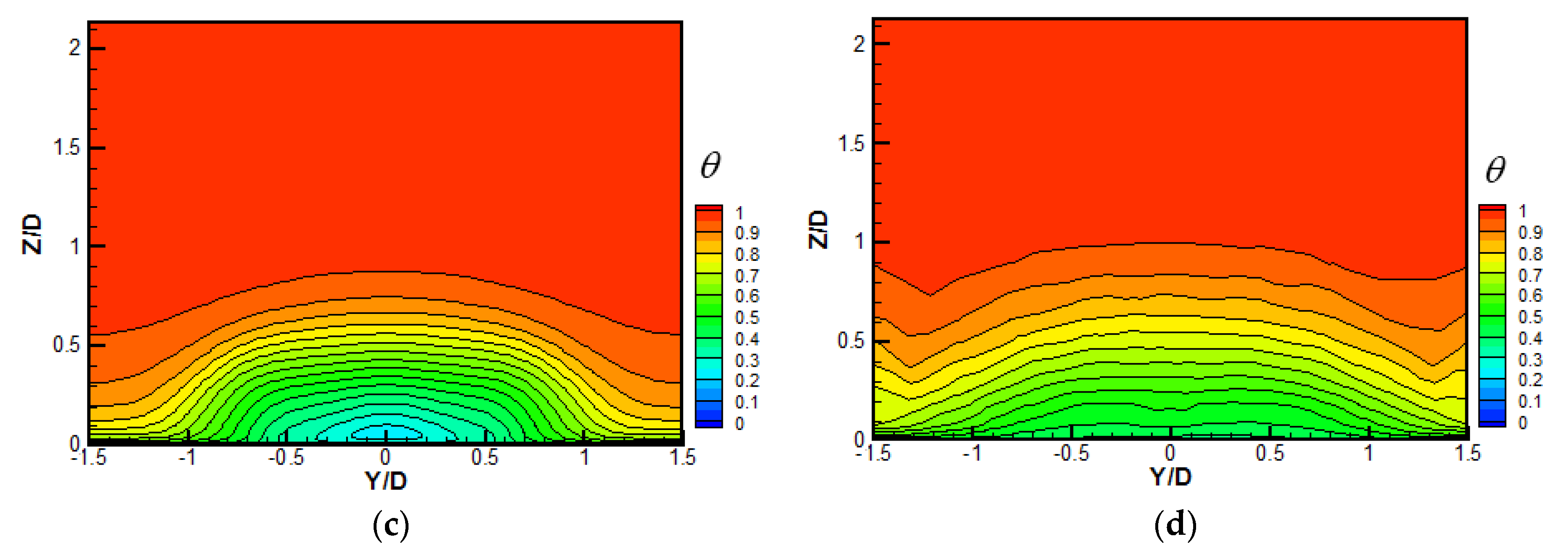
The contours of non-dimensional temperature over the surface X/D = 5 at M = 0.5 are shown in Figure 6. The coolant core is just above the wall surface for the CYL hole, and the coolant is attached to the wall surface. Because the additional anti-kidney-shaped vortex pair aside for the CIR_CRA hole has limited influence on the entire flow field, the non-dimensional temperature distribution is similar to that for the CYL hole. Compared with the CYL hole, the non-dimensional temperature contour shows a flat distribution, mainly attributed to the strong and large-scale anti-kidney-shaped vortex pair for the CRA1 and CRA2 holes. Comparatively, more coolants for the CRA2 hole are dragged sideways, and even non-dimensional temperature is distributed along the lateral span.
When the blowing ratio increases to M = 1.5, the streamline and non-dimensional temperature distributions over the surface X/D = 5 are depicted in Figure 7 and Figure 8, respectively. It is seen that the scale of the kidney-shaped vortex pair for the CYL hole is significantly enlarged, induced by the higher coolant momentum. For the CIR_CRA and CRA1 holes, attributed to the limited effect of the shallow crater, the kidney-shaped vortex pairs are influenced slightly with similar scales to that for the CYL hole. For the CRA2 hole, the deeper crater provides an anti-kidney-shaped vortex pair with strong intensity to overcome the original kidney-shaped vortex pair. Hence, the anti-kidney-shaped vortex pair dominates the flow structure at plane X/D = 5 for the CRA2 hole at M = 1.5. The non-dimensional temperature contours at M = 1.5 show similar bump-like shapes for the CYL, CIR_CRA, and CRA1 holes, i.e., the lowest temperature occurs around the hole centerline, and the temperature gradually rises along the lateral direction, and the coolant core is lifted off away from the wall surface. However, the CRA2 hole exhibits a dramatically different temperature contour at plane X/D = 5 from the other three holes. More coolants are allocated sideways due to the wider crater exit area of the CRA2 hole, and fewer coolants are concentrated near the hole centerline. The more important is that the coolants ejected from the CRA2 hole are attached to the wall surface, and the temperature is significantly reduced, especially sideways.
3.2. Overall Cooling Effectiveness
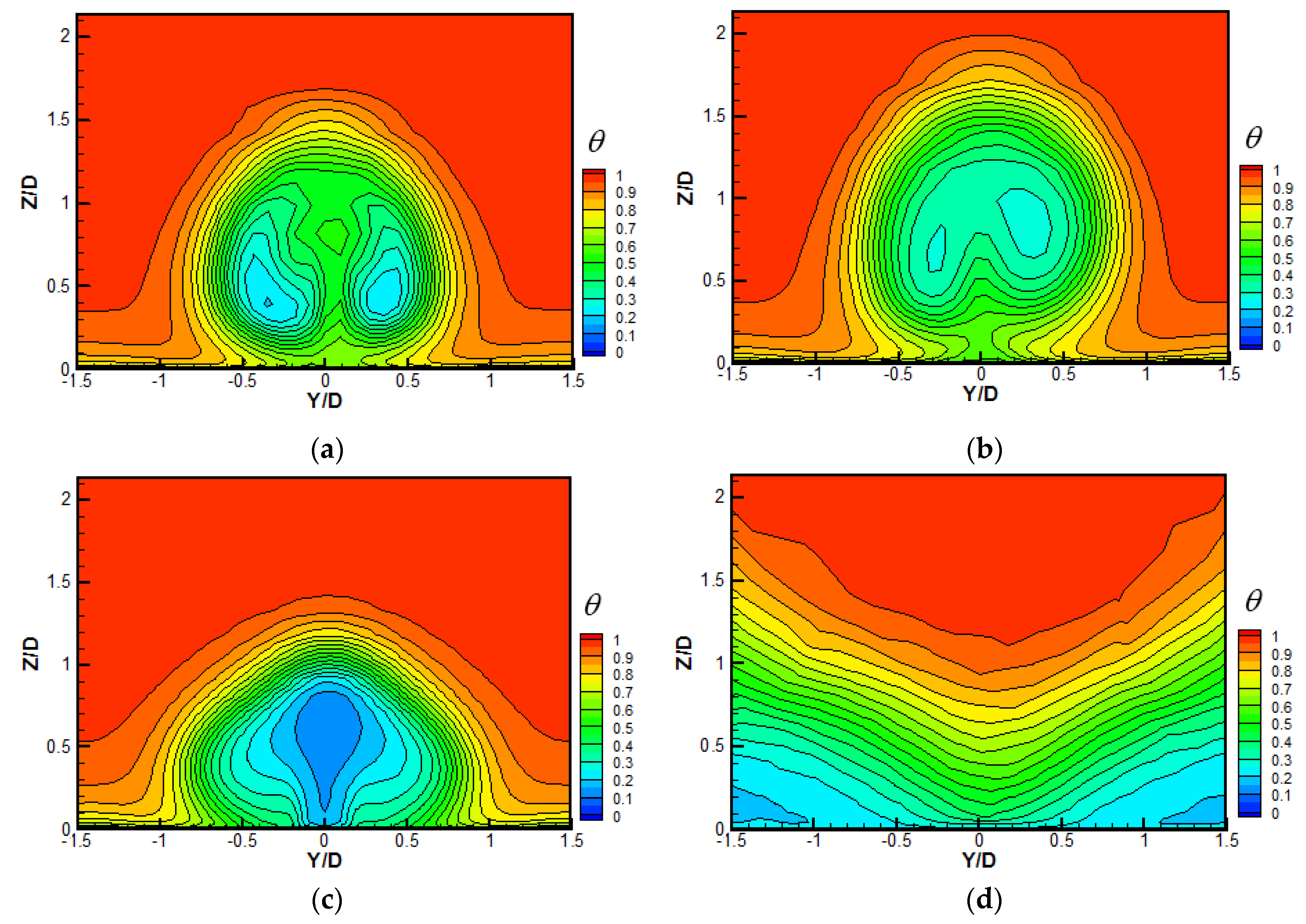
The contours of overall cooling effectiveness over the wall surface are shown in Figure 9 at M = 0.5 to 2.0. It is seen that the upstream region from the hole is cooled at any blowing ratio considering the conjugate heat transfer, which is a great difference from that studied under the adiabatic condition. The overall cooling effectiveness over the upstream region for any hole increases with the blowing ratio as the in-hole convection heat transfer strengthens. Generally, the CRA1 hole exhibits the highest local overall cooling effectiveness over the whole wall surface among the four holes studied at M = 0.5. However, the CRA2 hole provides the best overall cooling performance, and the CYL hole always has the lowest overall cooling performance at M = 1.0–2.0. For a specific hole, the variation of the local overall cooling effectiveness relative to the blowing ratio is dependent on the specific hole shape. For the CYL hole, as the blowing ratio increase since M > 1.0, the ejected coolants are lifted away from the wall surface by the kidney-shaped vortex pair. Hence fewer coolants for the CYL hole are covered in the downstream region, resulting in continuous deterioration of the overall cooling effectiveness with the increasing blowing ratio. The coolant lift-off is obvious for the CYL at M = 2.0, and a region with low overall cooling effectiveness is located far downstream from the hole exit between two rows of holes. Compared with the CYL hole, the CIR_CRA hole gives ejected coolant with a lower velocity resulting from the enlarged exit area, and a slight improvement in the overall cooling effectiveness can be obtained in the near-hole downstream region. The contoured cratered holes can provide major enhancements to the overall cooling effectiveness, mainly attributed to the improved ventilation of the coolants along the lateral direction. For the CRA1 hole, the best overall cooling performance occurs at M = 1.0. Nevertheless, the local overall cooling effectiveness increases monotonously with the blowing ratio for the CRA2 hole. The crater geometry variant can explain the difference between these two contoured cratered holes. The wider and deeper crater for the CRA2 hole induces a stronger anti-kidney-shaped vortex pair and much-improved coolant coverage, especially at the higher blowing ratios M = 1.0–2.0.
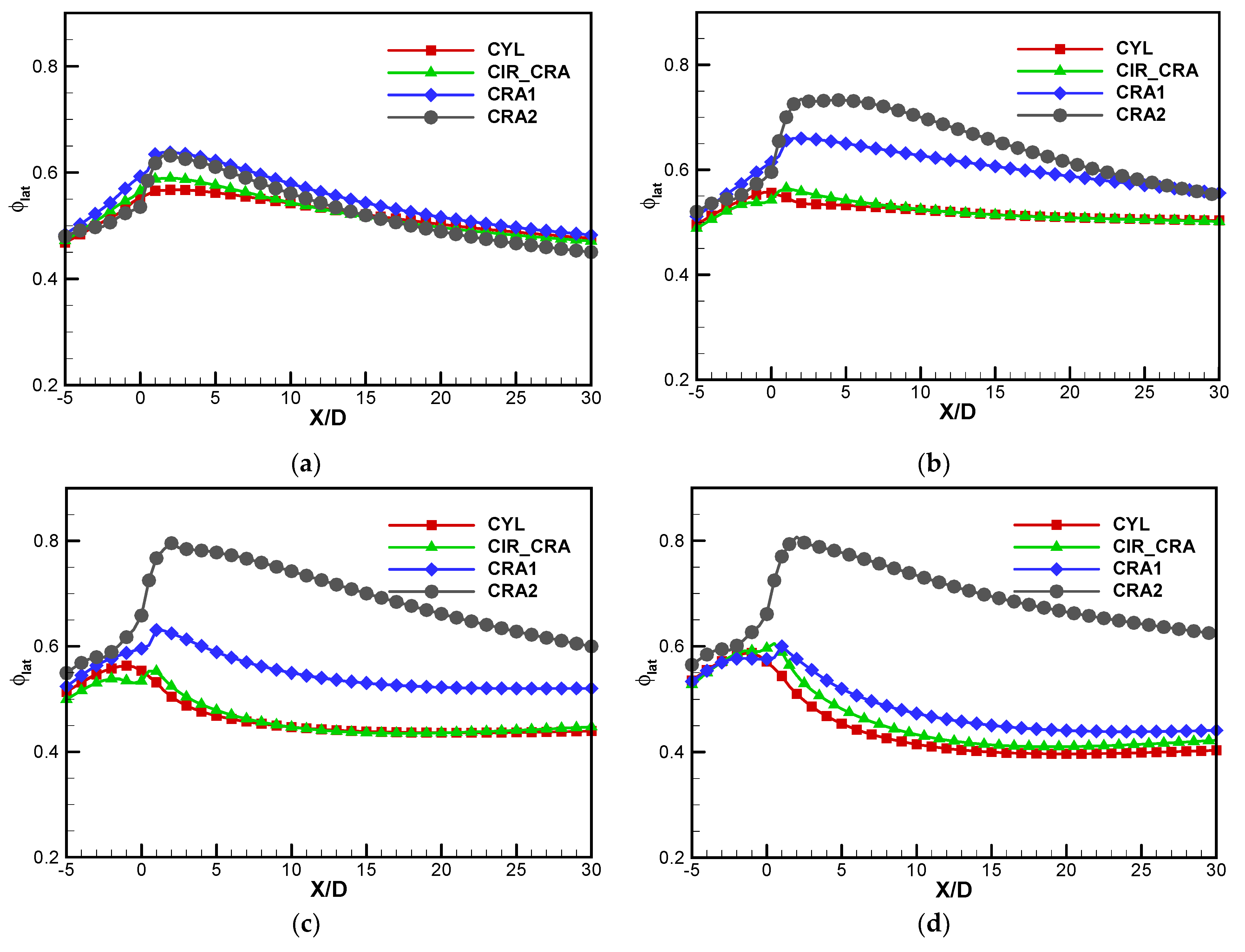
The laterally averaged overall cooling effectiveness profiles for the holes studied in the streamwise region −5 ≤ X/D ≤ 30 are further provided in Figure 10. The overall cooling effectiveness increases along the streamwise direction in the upstream region −5 ≤ X/D ≤ 0. The enhanced convective heat transfers in the hole, hence the wall surface closer to the hole exit could be cooled further. However, the overall cooling effectiveness almost decreases with the streamwise distance increase in the downstream region 0 ≤ X/D ≤ 30. At the lowest blowing ratio, M = 0.5, the laterally averaged overall cooling effectiveness slightly varies for the four holes. The CIR_CRA and CRA2 holes give higher values of laterally averaged cooling effectiveness than the CYL hole in the region 0 ≤ X/D ≤ 15, but lower values in the region X/D > 15. The CRA1 hole has a maximum increased laterally averaged cooling effectiveness by 0.072. When the blowing ratio increases to 1.0 and 1.5, the CIR_CRA hole provides very close overall cooling performance in the downstream region to the CYL hole, but the superiority of the contoured cratered holes is fully demonstrated. The improvements in the laterally averaged cooling effectiveness are 0.052–0.124 (the CRA1 hole) and 0.040–0.200 (the CRA2 hole) at M = 1.0, 0.042–0.125 (the CRA1 hole), 0.105–0.311 (the CRA2 hole) at M = 1.5 compared to the CYL hole, respectively. At M = 2.0, the three cratered holes yield higher laterally averaged cooling effectiveness than the CYL hole in the full region downstream of the hole exit. Comparatively, the enhancement for the CRA1 hole is 0.005–0.069 at M = 2.0, lower than those at M = 1.0 and 1.5. The advantage of the CRA2 hole is further enlarged with the enhancement of 0.089–0.327 at M = 2.0.
Figure 11 gives the area-averaged overall cooling effectiveness ϕarea, for the four holes at M = 0.5–2.0. The interesting area is the downstream region 0 ≤ X/D ≤ 30 over the full lateral distance −1.5 ≤ Y/D ≤ 1.5. It is found that the area-averaged overall cooling effectiveness decreases with the increase in blowing ratio for both the CYL and CIR_CRA holes. Compared with the CYL hole, the CIR_CRA gives roughly equal area-averaged overall cooling effectiveness at M = 0.5–1.5 and an improvement by 4.68% at M = 2.0. The area-averaged overall cooling effectiveness for the CRA1 hole arrives at its maximum value of 0.607 at M = 1.0 and decreases with further increasing the blowing ratio. The CRA2 hole gives the increasing area-averaged overall cooling effectiveness relative to the increase of blowing ratio in the region M = 0.5–2.0, but the rising tendency is slowed at a higher blowing ratio. The area-averaged overall cooling effectiveness for the CRA2 hole increases from 0.424 at M = 0.5 to the maximum value of 0.701 at M = 2.0. Among the four holes studied, the CRA1 hole performs the highest area-averaged cooling effectiveness with an enhancement of 5.58% at M = 0.5, but the CRA2 hole overwhelms at M = 1.0–2.0. The relative improvements in the area-averaged cooling effectiveness for the CRA2 hole are 25.28% at M = 1.0, 54.08% at M = 1.5, and 65.30% at M = 2.0, respectively.
3.3. The Effect of Biot Number
This section focuses on the impact of Biot number on the flow field, temperature field, and overall cooling effectiveness. It is concluded from the above section that the CRA2 hole model performs better overall cooling performance than the other three types of holes. Besides, the blowing ratio is usually medium or high (M ≥ 1.0) for the real turbine blade film cooling. Hence, the CRA2 hole model is selected for illustration in the following.
In the present study, the variation of the Biot number is accessed by changing the solid heat conductivity only. The other four Biot numbers of Bi = 0.026, 0.065, 0.26, and 0.65 and the adiabatic case are considered. Zhang et al. (2013) pointed out that when the solid heat conduction effect is omitted, the heat conductivity approaches zero, and the value of the Biot number approaches the infinity accordingly.
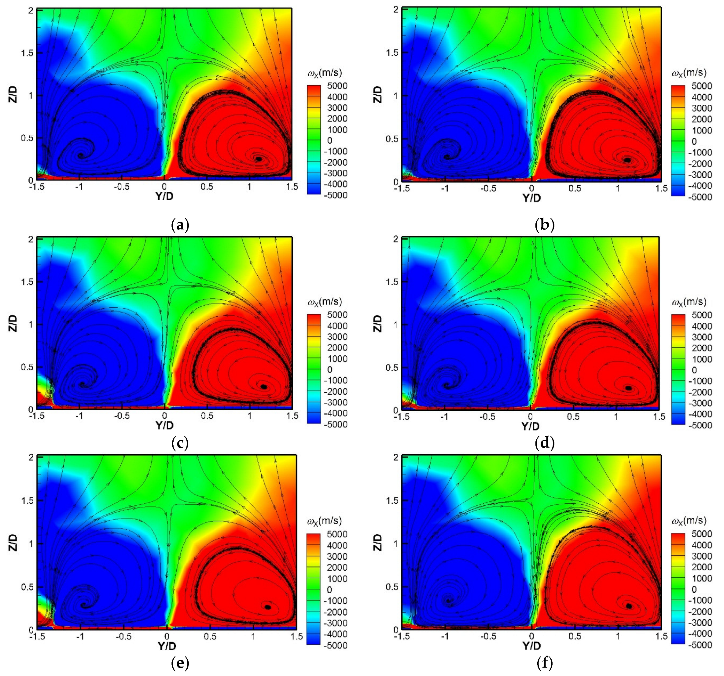
Figure 12 shows the streamline distributions and the contours of streamwise vorticity ωX over the surface X/D = 5 with different Biot numbers at M = 1.5. The flow structures and the streamwise vorticial contours change little with the variation of the Biot number, which means the solid heat conductivity has less impact on the film cooling flow field.
The non-dimensional temperature contours over the cross-section plane Y/D = 0 in the fluid and solid domains are given in Figure 13. When the solid heat conduction is considered, the coolants are heated by the mainstream hot air through the flat plate, increasing the temperature at the hole entrance. As the Biot number increases from 0.026 to 0.65, the area-averaged non-dimensional temperature at the hole entrance varies from 0.076 to 0.062, equal to 10.86K. Moreover, the Biot number significantly influences the temperature distribution in the flat plate near the hole. The coolant temperature inside the hole and the solid inner temperature near the hole with a high Biot number are lower than those with a low Biot number. The temperature gradient in the solid domain is higher at a higher Biot number, resulting in the possible higher thermal stress.
Figure 14 presents the overall cooling effectiveness contour over the wall surface for the CRA2 hole model at M = 1.5 with different Biot numbers. It is seen that the Biot number remarkably influences the profile of local overall cooling effectiveness. The profile is relatively uniform in streamwise and lateral directions with a high Biot number due to the stronger heat conduction. However, if the value of the Biot number is high, especially for the adiabatic case, the contour shape becomes wavy in the lateral direction, and the local overall cooling effectiveness in the streamwise direction varies in a larger range. Comparatively, the profile of the laterally averaged overall cooling effectiveness changes from a relatively flat shape at a low Biot number to an abrupt shape at a high Biot number.
The influence of the Biot number on the area-averaged overall cooling effectiveness for the CRA2 hole is shown in Figure 15. It can be seen that the Biot number plays an insensitive role in the area-averaged overall cooling effectiveness for the CRA2 hole model. Despite the local overall cooling effectiveness distribution varies remarkably with the change of Biot number, shown in Figure 14, the area-averaged overall cooling effectiveness provides the absolute deviations of 0.022–0.035 relative to the Biot number at blowing ratios M = 0.5–2.0, and the relative deviations of 3.40–5.38%. The small variation of the CRA hole model with Biot number in the current study is similar to that of the fan-shaped hole model reportedin [29]. The area-averaged overall cooling effectiveness for the CRA2 model firstly increases, then decreases with the increment of the Biot number. The smallest Biot number at either blowing ratio also gives the lowest value of area-averaged overall cooling effectiveness, mainly due to the highest consumption of cooling capability in the upstream region ahead of the cooling hole. However, the changing trend for the CRA2 hole is different from the monotonically decreasing tendency for the CYL hole model in [27]. Hence, the general tendency of the Biot number for the film cooling hole is suggested to be analyzed case by case.
Inspired by the concept of film cooling uniformity coefficient proposed by Javadi [32], the area-averaged overall cooling effectiveness uniformity coefficient σarea, is presented to evaluate the gross uniformity over the interested region, which is given as follows:
If the value of σarea is 1.0, it means that the uniform coolant spreads in the lateral and streamwise directions with a theoretical zero thermal gradient. Hence, the high value approaching 1.0 for σarea is pursued for a specific film cooling hole scheme combined with a high value of area-averaged overall cooling effectiveness.
Figure 16 further presented the influence of the Biot number on the area-averaged overall cooling effectiveness uniformity coefficient for the CRA2 hole model at different blowing ratios. It is found that the Biot number provides a significant impact on the cooling uniformity coefficient σarea at either blowing ratio. For example, as the Biot number increases from 0.026 to 0.65, σarea decreases monotonously from 0.950 to 0.846 at M = 0.5. For the low Biot number configuration, the strong heat conduction effect evens the temperature distribution in lateral and streamwise directions, leading to a high value of σarea. Moreover, the increase of blowing ratio yields the increasing cooling uniformity coefficient σarea for either Biot number configuration, attributed to better coolant coverage over the wall surface for the CRA2 model.
4. Conclusions
In the present study, four cooling holes, i.e., a cylindrical hole, a concentric circular cratered hole, and two contoured cratered holes with different dimensions, are investigated for the flat plate film cooling under the conjugate heat transfer condition. The comparisons of flow structure, temperature distribution, and overall cooling effectiveness are performed among these four holes based on the CFD predicted results. The effect of the solid heat conductivity is further studied for the CRA2 hole. The main conclusions are summarized as follows:
- Compared with the cylindrical hole (CYL), the additional anti-kidney-shaped vortex pair for the cratered hole improves the coolant coverage and the overall cooling effectiveness over the wall surface. The overall cooling effectiveness improvement amplitude depends on the crater shape, geometry parameters, and the specific blowing ratio. The concentric circular cratered hole (CIR_CRA) gives a comparative overall cooling performance to the cylindrical hole at M = 0.5–1.5, but an improvement of 4.68% at M = 2.0. Comparatively, the contoured cratered holes provide large enhancements. The maximum area-averaged overall cooling effectiveness increases are 5.58% for the CRA1 hole at M = 0.5 and 25.28–65.30% for the CRA2 hole at M = 1.0–2.0, respectively.
- For the CRA2 hole model, the variation of Biot number influences little on the flow structure but significantly on the local overall cooling effectiveness distribution and temperature gradient in the solid domain. Furthermore, the area-averaged overall cooling effectiveness is insensitive to the Biot number, but the area-averaged overall cooling effectiveness uniformity coefficient strongly depends on the specific value of the Biot number. As the Biot number increases, the temperature gradient in the solid near the hole and the cooling uniformity both increase, raising a possible high thermal stress.
Author Contributions
Conceptualization, methodology, validation, and writing—original draft preparation and funding acquisition, C.Z.; formal analysis, data curation and visualization, W.W.; writing—review and editing, Z.W.; investigation, supervision, and funding acquisition; Z.T. All authors have read and agreed to the published version of the manuscript.
Funding
This research was funded by the National Natural Science Foundation of China, grant numbers 51976139 and 51506150.
Institutional Review Board Statement
Not applicable.
Informed Consent Statement
Not applicable.
Data Availability Statement
Not applicable.
Conflicts of Interest
The authors declare no conflict of interest.
References
- Goldstein, R.J. Film Cooling. Adv. Heat Transf. 1971, 7, 321–379. [Google Scholar]
- Sinha, A.K.; Bogard, D.G.; Crawford, M.E. Film-cooling effectiveness downstream of a single row of holes with variable density ratio. J. Turbomach. 1991, 113, 442–449. [Google Scholar] [CrossRef]
- Goldstein, R.J.; Jin, P.; Olson, R.L. Film cooling effectiveness and mass/heat transfer coefficient downstream of one row of discrete holes. J. Turbomach. 1999, 121, 225–232. [Google Scholar] [CrossRef]
- Baldauf, S.M.; Schulz, A.; Wittig, S. High-resolution measurements of local effectiveness from discrete hole film cooling. J. Turbomach. 2001, 123, 758–765. [Google Scholar] [CrossRef]
- Goldstein, R.J.; Eckert, E.; Burggraf, F. Effects of hole geometry and density on three-dimensional film cooling. Int. J. Heat Mass Transf. 1974, 17, 596–607. [Google Scholar] [CrossRef]
- Gritsch, M.; Colban, W.; Schär, H.; Döbbeling, K. Effect of hole geometry on the thermal performance of fan-shaped film cooling holes. J. Turbomach. 2005, 127, 718–725. [Google Scholar] [CrossRef]
- Lee, K.D.; Kim, K.Y. Shape optimization of a fan-shaped hole to enhance film-cooling effectiveness. Int. J. Heat Mass Transf. 2010, 53, 2996–3005. [Google Scholar] [CrossRef]
- Krishna, A.V.G.; Parammasivam, K.M. Thermal barrier coated surface modifications for gas turbine film cooling: A review. J. Therm. Anal. Calorim. 2021, 146, 545–580. [Google Scholar] [CrossRef]
- Tran, N.; Nguyen, S.; Ho, S.; Kapat, J. Prediction of adiabatic effectiveness of various cratered film hole configurations: Sensitivity analysis for the rectangle shaped mask. In Proceedings of the 48th AIAA Aerospace Sciences Meeting Including the New Horizons Forum and Aerospace Exposition, Orlando, FL, USA, 4–7 January 2010. [Google Scholar]
- Lu, Y.P.; Dhungel, A.; Ekkad, S.; Bunker, R. Film cooling measurements for cratered cylindrical inclined holes. J. Turbomach. 2009, 131, 011005. [Google Scholar] [CrossRef]
- Khalatov, A.A.; Panchenko, N.A.; Severi, S.D. Application of cylindrical, triangular and hemispherical dimples in the film cooling technology. J. Phys. Conf. Ser. 2017, 891, 012145. [Google Scholar] [CrossRef]
- Khalatov, A.A.; Shi-Ju, E.; Wang, D.Y.; Borisov, I. Film cooling evaluation of a single array of triangular craters. Int. J. Heat Mass Transf. 2020, 159, 120055. [Google Scholar] [CrossRef]
- Kalghatgi, P.; Acharya, S. Improved film cooling effectiveness with a round film cooling hole embedded in a contoured crater. J. Turbomach. 2015, 137, 101006. [Google Scholar] [CrossRef]
- Kalghatgi, P.; Acharya, S. Flow dynamics of a film cooling jet issued from a round hole embedded in contoured crater. J. Turbomach. 2019, 141, 081006. [Google Scholar] [CrossRef]
- An, B.T.; Liu, J.J.; Zhang, X.D.; Zhou, S.J.; Zhang, C. Film cooling effectiveness measurements of a near surface streamwise diffusion hole. Int. J. Heat Mass Transf. 2016, 103, 1–13. [Google Scholar] [CrossRef]
- Fu, J.L.; Bai, L.C.; Zhang, C.; Ju, P.F. Film cooling performance for cylindrical holes embedded in contoured craters: Effect of the crater depth. J. Appl. Mech. Tech. Phys. 2019, 60, 1068–1076. [Google Scholar] [CrossRef]
- Bai, L.C.; Zhang, C.; Tong, Z.T.; Ju, P.F. Optimization of geometric parameters of cylindrical film cooling hole with contoured craters to enhance film-cooling effectiveness. Thermophys. Aeromech. 2021, 28, 835–848. [Google Scholar] [CrossRef]
- Bohn, D.; Ren, J.; Kusterer, K. Conjugate heat transfer analysis for film cooling configurations with different hole geometries. In Proceedings of the ASME Turbo Expo 2003, collocated with the 2003 International Joint Power Generation Conference, Atlanta, GA, USA, 16–19 June 2003. [Google Scholar]
- Slilieti, M.; Kassab, A.; Divo, E. Film cooling effectiveness: Comparison of adiabatic and conjugate heat transfer CFD models. Int. J. Therm. Sci. 2009, 48, 2237–2248. [Google Scholar] [CrossRef]
- Ghorab, M.G. Adiabatic and conjugate cooling effectiveness of a new hybrid scheme. Int. J. Therm. Sci. 2011, 50, 965–983. [Google Scholar] [CrossRef]
- Albert, J.E.; Bogard, D.G. Measurements of adiabatic film and overall cooling effectiveness on a turbine vane pressure side with a trench. J. Turbomach. 2013, 135, 051007. [Google Scholar] [CrossRef]
- Kusterer, K.; Hagedorn, T.; Bohn, D.; Sugimoto, T.; Tanaka, R. Improvement of a film-cooled blade by application of the conjugate calculation technique. J. Turbomach. 2006, 128, 572–578. [Google Scholar] [CrossRef]
- Alizadeh, M.; Izadi, A.; Fathi, A. Sensitivity analysis on turbine blade temperature distribution using conjugate heat transfer simulation. J. Turbomach. 2014, 136, 011001. [Google Scholar] [CrossRef]
- Wang, Z.; Zhang, C.; Du, W.J.; Li, S.J. Multi-field coupling analysis on the film-cooling with transverse and arched trenches. J. Therm. Sci. Tech. 2019, 14, JTST0012. [Google Scholar] [CrossRef] [Green Version]
- Fu, J.L.; Cao, Y.; Zhang, C.; Zhu, J.Q. Investigation of the conjugate heat transfer and flow field for a flat plate with combined film and impingement cooling. J. Therm. Sci. 2020, 29, 955–971. [Google Scholar] [CrossRef]
- Bryant, C.E.; Rutledge, J.L. A computational technique to evaluate the relative influence of internal and external cooling on overall effectiveness. J. Turbomach. 2020, 142, 051008. [Google Scholar] [CrossRef]
- Zhang, C.; Liu, J.J.; Wang, Z.; An, B.T. The effects of biot number on the conjugate film Cooling effectiveness under different blowing ratios. In Proceedings of the ASME Turbo Expo 2013: Turbine Technical Conference and Exposition, San Antonio, TX, USA, 3–7 June 2013. [Google Scholar]
- Liu, X.B.; Zhang, C.; Song, L.M.; Li, J. Influence of biot number and geometric parameters on the overall cooling effectiveness of double wall structure with pins. Appl. Therm. Eng. 2021, 198, 117439. [Google Scholar] [CrossRef]
- Zhang, P. Investigation of Film Cooling and Combined Cooling Using Conjugate Heat Transfer Method. Master’s Thesis, University of Chinese Academy of Sciences, Beijing, China, 2015. [Google Scholar]
- Bai, L.C. Research on Optimization Design and Thermal Coupling Analysis of the Cratered Hole. Master’s Thesis, Tianjin University of Technology, Tianjin, China, 2021. [Google Scholar]
- Fric, T.F.; Roshko, A. Vortical structure in the wake of a transverse jet. J. Fluid Mech. 1994, 277, 1–47. [Google Scholar] [CrossRef] [Green Version]
- Javadi, K. Introducing film cooling uniformity coefficient. Heat Transf. Eng. 2018, 39, 180–193. [Google Scholar] [CrossRef]
Figure 1.
Film cooling holes investigated. (a) cylindrical hole (CYL); (b) circular cratered hole (CIR_CRA); (c) contoured cratered hole (CRA1); (d) contoured cratered hole (CRA2).
Figure 1.
Film cooling holes investigated. (a) cylindrical hole (CYL); (b) circular cratered hole (CIR_CRA); (c) contoured cratered hole (CRA1); (d) contoured cratered hole (CRA2).

Figure 2.
Computational model. (a) cross-section view; (b) solid domain for CRA2 model.

Figure 3.
Computational grids. (a) the CIR_CRA model; (b) the CRA1 model.

Figure 4.
Turbulence model validation. (a) Laterally averaged overall cooling effectiveness; (b) Laterally averaged adiabatic cooling effectiveness.
Figure 4.
Turbulence model validation. (a) Laterally averaged overall cooling effectiveness; (b) Laterally averaged adiabatic cooling effectiveness.

Figure 5.
Streamline distributions over the surface X/D = 5 at M = 0.5. (a) CYL; (b) CIR_CRA; (c) CRA1; (d) CRA2.
Figure 5.
Streamline distributions over the surface X/D = 5 at M = 0.5. (a) CYL; (b) CIR_CRA; (c) CRA1; (d) CRA2.

Figure 6.
Contours of non-dimensional temperature over the surface X/D = 5 at M = 0.5. (a) CYL; (b) CIR_CRA; (c) CRA1; (d) CRA2.
Figure 6.
Contours of non-dimensional temperature over the surface X/D = 5 at M = 0.5. (a) CYL; (b) CIR_CRA; (c) CRA1; (d) CRA2.


Figure 7.
Streamline distributions over the surface X/D = 5 at M = 1.5. (a) CYL; (b) CIR_CRA; (c) CRA1; (d) CRA2.
Figure 7.
Streamline distributions over the surface X/D = 5 at M = 1.5. (a) CYL; (b) CIR_CRA; (c) CRA1; (d) CRA2.


Figure 8.
Contours of non-dimensional temperature over the surface X/D = 5 at M = 1.5. (a) CYL; (b) CIR_CRA; (c) CRA1; (d) CRA2.
Figure 8.
Contours of non-dimensional temperature over the surface X/D = 5 at M = 1.5. (a) CYL; (b) CIR_CRA; (c) CRA1; (d) CRA2.

Figure 9.
Local overall cooling effectiveness over the wall surface at various blowing ratios. (a) M = 0.5; (b) M = 1.0; (c) M = 1.5; (d) M = 2.0.
Figure 9.
Local overall cooling effectiveness over the wall surface at various blowing ratios. (a) M = 0.5; (b) M = 1.0; (c) M = 1.5; (d) M = 2.0.

Figure 10.
Laterally averaged overall cooling effectiveness profiles at various blowing ratios. (a) M = 0.5; (b) M = 1.0; (c) M = 1.5; (d) M = 2.0.
Figure 10.
Laterally averaged overall cooling effectiveness profiles at various blowing ratios. (a) M = 0.5; (b) M = 1.0; (c) M = 1.5; (d) M = 2.0.

Figure 11.
Area-averaged overall cooling effectiveness at M = 0.5–2.0.

Figure 12.
Streamlines and streamwise vorticities over the surface X/D = 5 with various heat conductivities at M = 1.5. (a) Bi = 0.026; (b) Bi = 0.065; (c) Bi = 0.13; (d) Bi = 0.26; (e) Bi = 0.65; (f) adiabatic.
Figure 12.
Streamlines and streamwise vorticities over the surface X/D = 5 with various heat conductivities at M = 1.5. (a) Bi = 0.026; (b) Bi = 0.065; (c) Bi = 0.13; (d) Bi = 0.26; (e) Bi = 0.65; (f) adiabatic.

Figure 13.
Non-dimensional temperature distribution over the surface Y/D = 0 at M = 1.5. (a) Bi = 0.026; (b) Bi = 0.065; (c) Bi = 0.13; (d) Bi = 0.26; (e) Bi = 0.65; (f) adiabatic.
Figure 13.
Non-dimensional temperature distribution over the surface Y/D = 0 at M = 1.5. (a) Bi = 0.026; (b) Bi = 0.065; (c) Bi = 0.13; (d) Bi = 0.26; (e) Bi = 0.65; (f) adiabatic.

Figure 14.
Local overall cooling effectiveness over the wall surface for the CRA2 hole at M = 1.5. (a) Bi = 0.026; (b) Bi = 0.065; (c) Bi = 0.13; (d) Bi = 0.26; (e) Bi = 0.65; (f) adiabatic.
Figure 14.
Local overall cooling effectiveness over the wall surface for the CRA2 hole at M = 1.5. (a) Bi = 0.026; (b) Bi = 0.065; (c) Bi = 0.13; (d) Bi = 0.26; (e) Bi = 0.65; (f) adiabatic.

Figure 15.
Influence of Biot number on area-averaged overall cooling effectiveness at M = 0.5–2.0.

Figure 16.
Influence of Biot number on area-averaged overall cooling effectiveness uniformity coefficient at M = 0.5–2.0.
Figure 16.
Influence of Biot number on area-averaged overall cooling effectiveness uniformity coefficient at M = 0.5–2.0.

Publisher’s Note: MDPI stays neutral with regard to jurisdictional claims in published maps and institutional affiliations. |
© 2022 by the authors. Licensee MDPI, Basel, Switzerland. This article is an open access article distributed under the terms and conditions of the Creative Commons Attribution (CC BY) license (https://creativecommons.org/licenses/by/4.0/).
Share and Cite
MDPI and ACS Style
Zhang, C.; Wang, W.; Wang, Z.; Tong, Z. Conjugate Heat Transfer Simulation of Overall Cooling Performance for Cratered Film Cooling Holes. Machines 2022, 10, 395. https://0-doi-org.brum.beds.ac.uk/10.3390/machines10050395
AMA Style
Zhang C, Wang W, Wang Z, Tong Z. Conjugate Heat Transfer Simulation of Overall Cooling Performance for Cratered Film Cooling Holes. Machines. 2022; 10(5):395. https://0-doi-org.brum.beds.ac.uk/10.3390/machines10050395
Chicago/Turabian StyleZhang, Chao, Wenzhuang Wang, Zhan Wang, and Zhiting Tong. 2022. "Conjugate Heat Transfer Simulation of Overall Cooling Performance for Cratered Film Cooling Holes" Machines 10, no. 5: 395. https://0-doi-org.brum.beds.ac.uk/10.3390/machines10050395
Note that from the first issue of 2016, this journal uses article numbers instead of page numbers. See further details here.