Article

Analysis of 3-DOF Cutting Stability of Titanium Alloy Helical Milling Based on PKM and Machining Quality Optimization

Key Laboratory of Mechanism Theory and Equipment Design of Ministry of Education, Tianjin University, Tianjin 300072, China
*
Author to whom correspondence should be addressed.
Submission received: 2 May 2022 / Revised: 18 May 2022 / Accepted: 19 May 2022 / Published: 21 May 2022
(This article belongs to the Special Issue New Frontiers in Parallel Robots)

Abstract

:
Aiming at the requirements of titanium alloy holes in aircraft industry, the 3-DOF cutting stability and surface quality optimization of parallel kinematic manipulator (PKM) are studied. The variation of natural frequencies with the end-effector position of the PKM is analyzed. The cutting force model of titanium alloy helical milling based PKM is developed, and the cutting force coefficients are identified. The prediction model for 3-DOF the stability of helical milling based on the PKM is established through a Semi-Discrete method, and the stability lobes are obtained. The correctness of the stability lobes is verified by subjecting the cutting force signal to time-frequency transformation and roughness detection. The step-cutter is used for machining process improvement to enhance the stability domain. The method proposed in this paper can provide a reference for further optimization of the prediction and optimization of the milling process of difficult-to-process materials based on PKM in the future.

1. Introduction

The quality requirements of the aircraft components are stringent because of their harsh working environment [1]. Besides, the aircraft components have the characteristics of large size, high requirements of precision and surface quality, high mechanical properties and high difficulty of material processing, which have posed great challenges to the traditional processing equipment and technology. Industrial robots have great advantages in milling process on the large aircraft components due to its high reconfigurablity. The hybrid PKM combines the advantages of high flexibility of series manipulator and large working space, high stiffness precision of parallel manipulator. The processing of hole making is an important part of aircraft assembly process in the aircraft industry. Compared with the traditional drilling process, helical milling has the advantages of less cutting force, simple process and low tool loss [2], which makes it more advantageous in the machining process of titanium alloy and other difficult-to-process materials in the aircraft industry. Therefore, it is necessary for the research of helical milling based on the hybrid PKM to improve the precision of hole making and improve the assembly efficiency. However, it is easy to occur the machining instability when machining the difficult-to-process materials, since the stiffness of the hybrid PKM is less than five-axis machine tool. Besides, the parameters of the hybrid PKM may vary with the position. Therefore, it is of great significance to analyze the machining performance of the hybrid PKM under different positions, study its cutting stability and machining quality and optimize the machining parameters, which may improve the machining quality.
Many scholars have carried out some related studies in cutting stability and machining quality. Altintas et al. [3] established a virtual prototype with the structure of the hybrid machine tool, which was used to study the stiffness, dynamics, vibration characteristics and cutting stability of the mechanism. The precision and machining performance of the hybrid machine tool were systematically analyzed on the basis of the analysis results. Piras et al. [4] analyzed the dynamic characteristics of the planar parallel mechanism with the simplified limbs with the help of the Finite Element Method. The variation of the natural frequency and the mode under different positions and attitude were obtained. Luo et al. [5] established an elastodynamics model which could predict the frequency response function (FRF) of 3-RPS parallel manipulator quickly based on the substructure synthesis technology. The natural frequency, frequency response and vibration mode of the parallel manipulator were simulated, and the variation trend of these parameters among the workspace was given. Law et al. [6] studied FRFs at the end of the system under different configurations based on the PKM by adopting modal polycondensation and substructure synthesis, and solved the cutting stability under different configurations by using a reduced order model. The relationship of dynamic characteristics, cutting stability and configurations was studied. Mousavi et al. [7] established a parameterized model to predict the dynamic characteristics and stability limit along the machining trajectory of the manipulator to achieve the maximum stability domain of the machining process. Li et al. [8] studied the dynamic behavior of the machine milling system and the chatter stability domain according to the stiffness model and the dynamic milling force model. The stability lobes of the whole system were obtained, and the experiments were carried out to verify the results. Shi et al. [9] took TriMule hybrid PKM as an example, and established the overall cutting dynamics model considering the hybrid PKM by analytical method. The cutting stability of TriMule was analyzed in the working space according to the cutting dynamics model. The trend of the 2-dimensional stability lobe diagram in the plane of workpiece with the variation of the position of the end-effector of hybrid PKM was obtained. Cao et al. [10] investigated the interaction mechanism between the spindle-tool system. Based on the process stability and surface quality of workpiece, a cutting parameter selection method is proposed from the perspective of machining stability. Mejri et al. [11] quantify the dynamic behavior s variation of an ABB IRB 6660 robot equipped with a high-speed machining (HSM) spindle in its workspace, and analyze the consequences in terms of machining stability. The results show that an adjustment of the cutting conditions must accompany the change of robot posture during machining to ensure stability.
Titanium alloy is widely used in the aircraft industry due to its excellent material characteristics. However, its surface quality directly affects its mechanical properties and practical life. Therefore, in terms of the surface machining quality and process of titanium alloy, Polini et al. [12] carried out cutting experiments on Ti6-Al4-V using tools of different materials. The influence of cutting force and tool wear on the machining surface quality were analyzed. It is found that TiAlN single-coated carbide tool had the better surface quality and longer tool life. Zain et al. [13] had given the optimal solution of cutting conditions with genetic algorithm to obtain the minimum surface roughness on the basis of radial rake processing parameters. The regression model was established according to the practical machining example. An optimal regression model was established to determine the fitness function of the genetic algorithm. The minimum surface roughness of the samples was reduced by about 27%. Munoz-escalona et al. [14] proposed a geometric model for predicting the surface roughness based on geometric analysis of tool path. The accuracy of surface roughness prediction reached 98% without considering the side wear of the tool, which was suitable for arbitrary diameter, arbitrary number of teeth and arbitrary nose radius of the tool. Liu et al. [15] established a mathematical model to calculate the uncut thickness and to describe the dynamic behavior of micro-milling force, including the combined influences of tool runout, minimum uncut thickness and edge plowing. Zhang et al. [16] designed the two-step milling (roughing and then finishing) experiments of Ti-6Al-4V titanium alloy to analyze the effect of different roughing parameters on the cutting force of roughing and finishing, the residual stress of finishing surface and the microstructure. The microstructural characteristics in terms of residual stress, XRD patterns, phase composition and content and nano-scale crystallite size of machined surface layer were characterized to reveal the machined surface layer quality adjustment and controlling mechanism from the prospective of the microscopic scale.
The static and dynamic stiffness of hybrid PKM is weaker than that of a 5-axis machine tool due to its structural characteristics. In order to meet the requirements of aircraft industry, it is necessary to study the cutting stability considering the PKM, when the PKM is applied to titanium alloy helical milling. The surface quality is analyzed to optimize the machining parameters and machining processing according to the above analysis. Few of the above studies have concerned this aspect. Therefore, this paper will arrange it as follows: in Section 2, a modal analysis of the PKM is performed and cutting forces model of helical milling based on PKM are established. The cutting forces coefficients are identified and the 3-DOF cutting dynamic model of helical milling-based PKM is established accordingly. In Section 3, the cutting experimental platform and modal experimental platform based on the PKM named TriMule are built, and cutting experiments and hammering modal experiments are performed. In Section 4, the experimentally obtained data are analyzed and the stability lobes for titanium alloy helical milling based PKM are obtained and validated. The step-cutter is used to optimize the machining process to improve the stability domain, and the optimization effect is demonstrated experimentally. The conclusion is given in Section 5.

2. Cutting Stability Analysis Based on Hybrid PKM

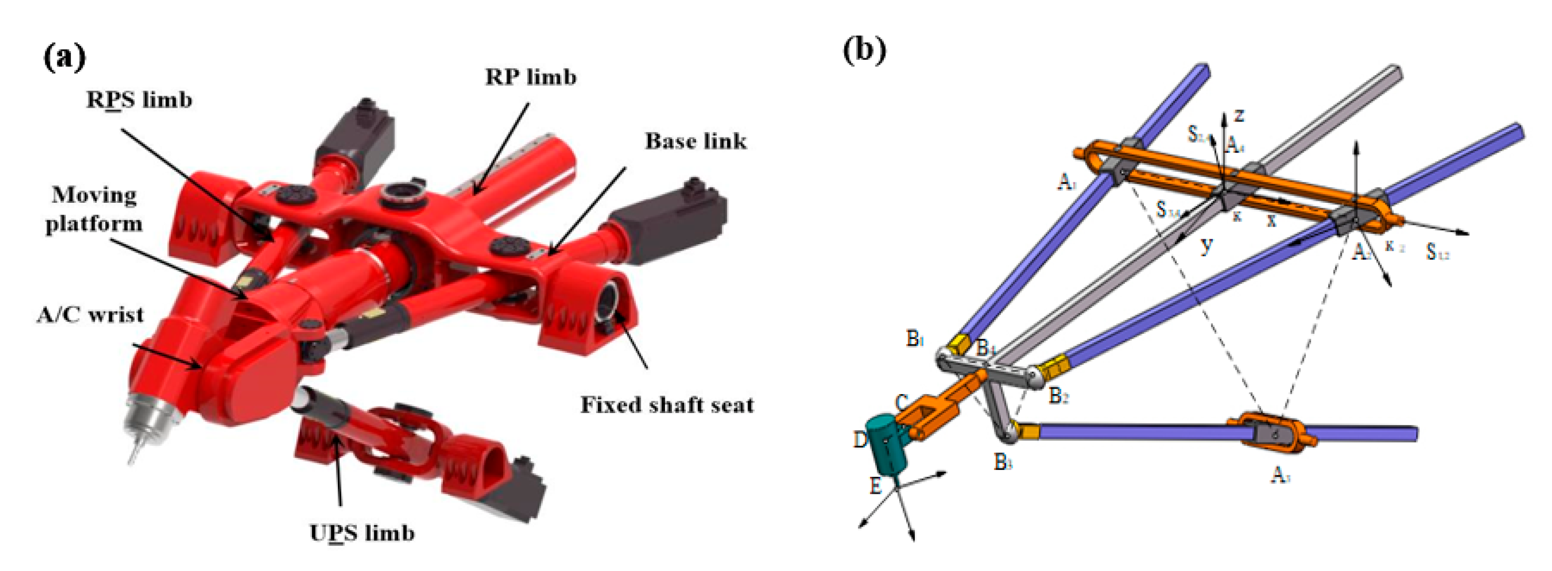
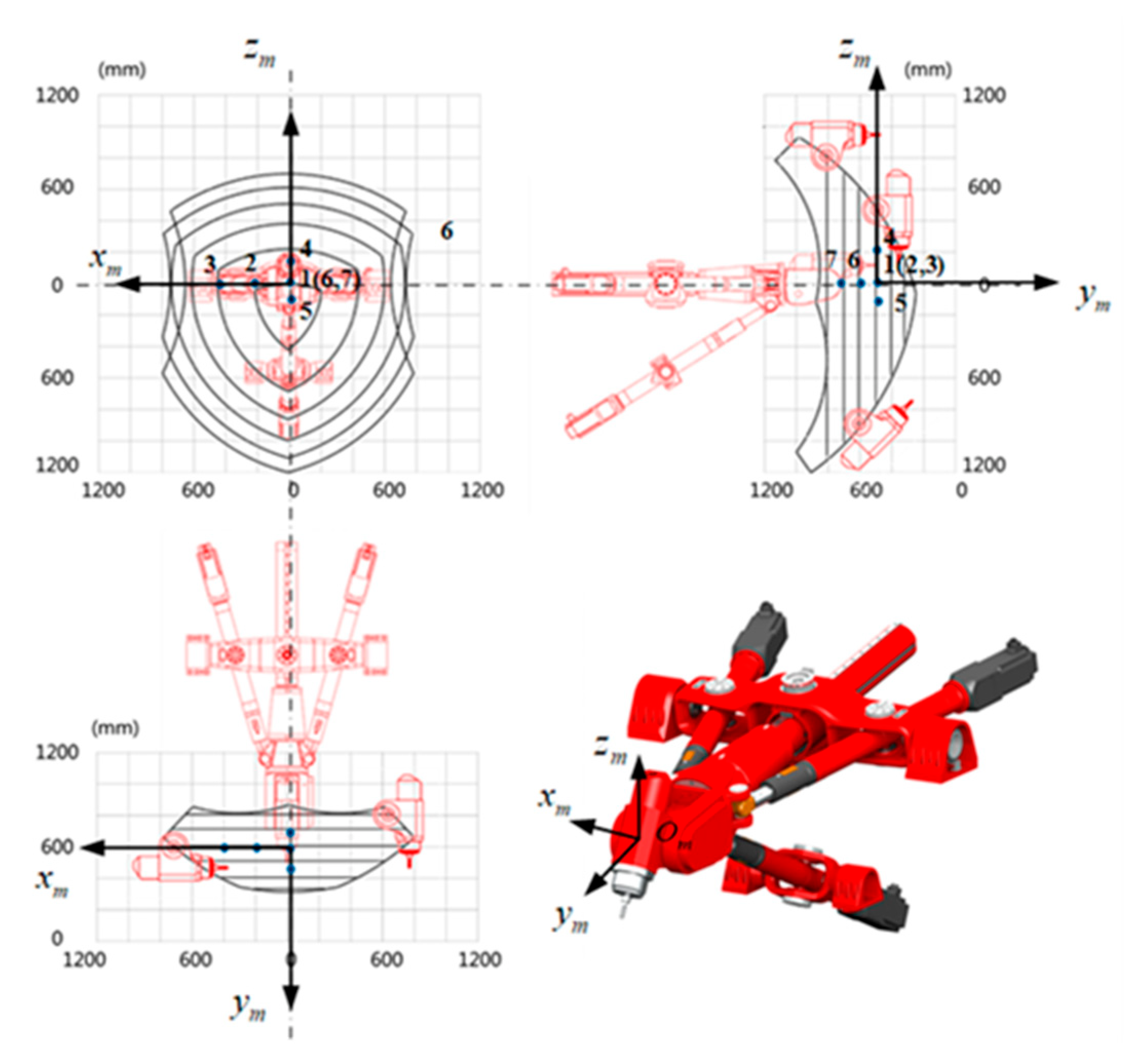
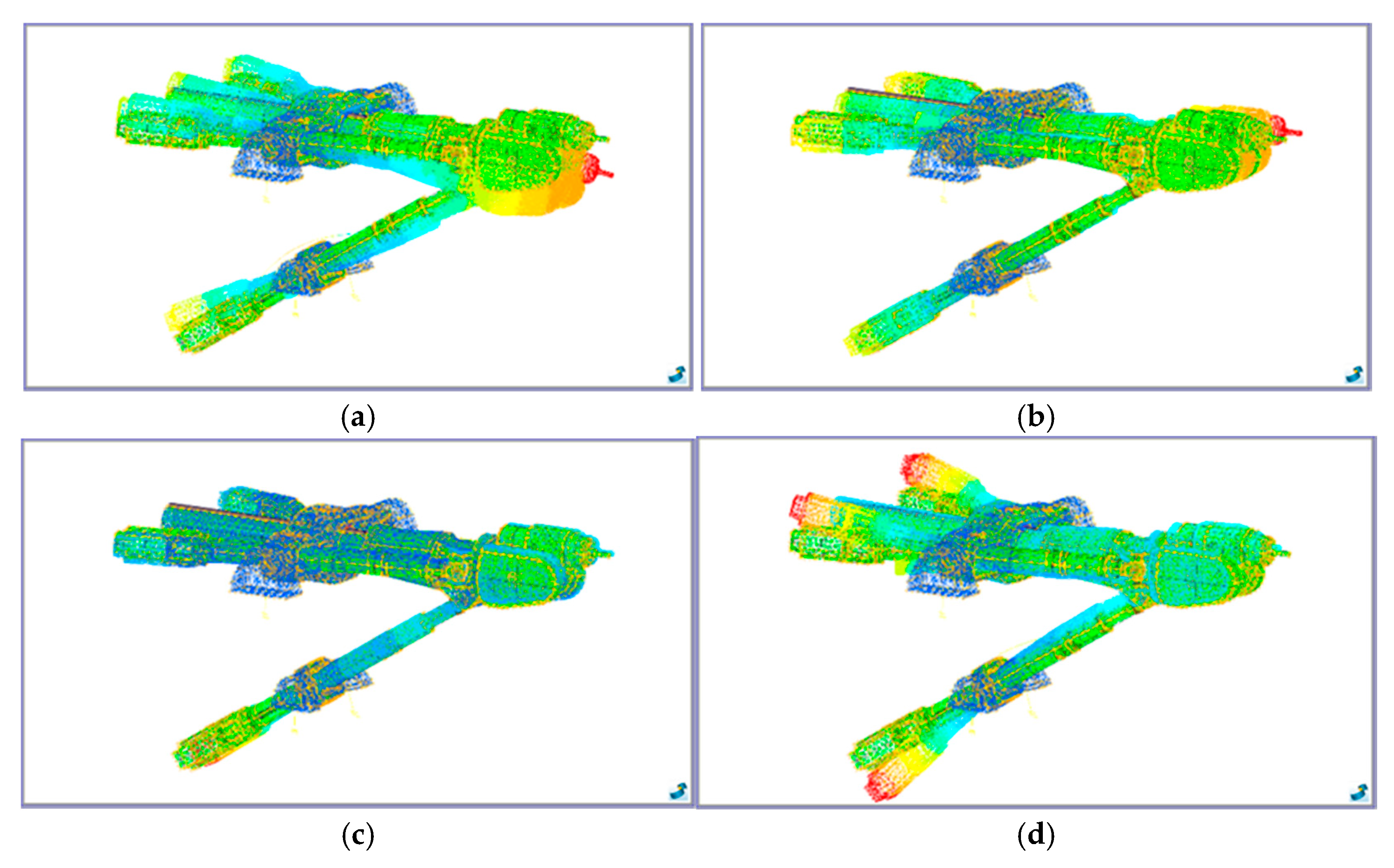
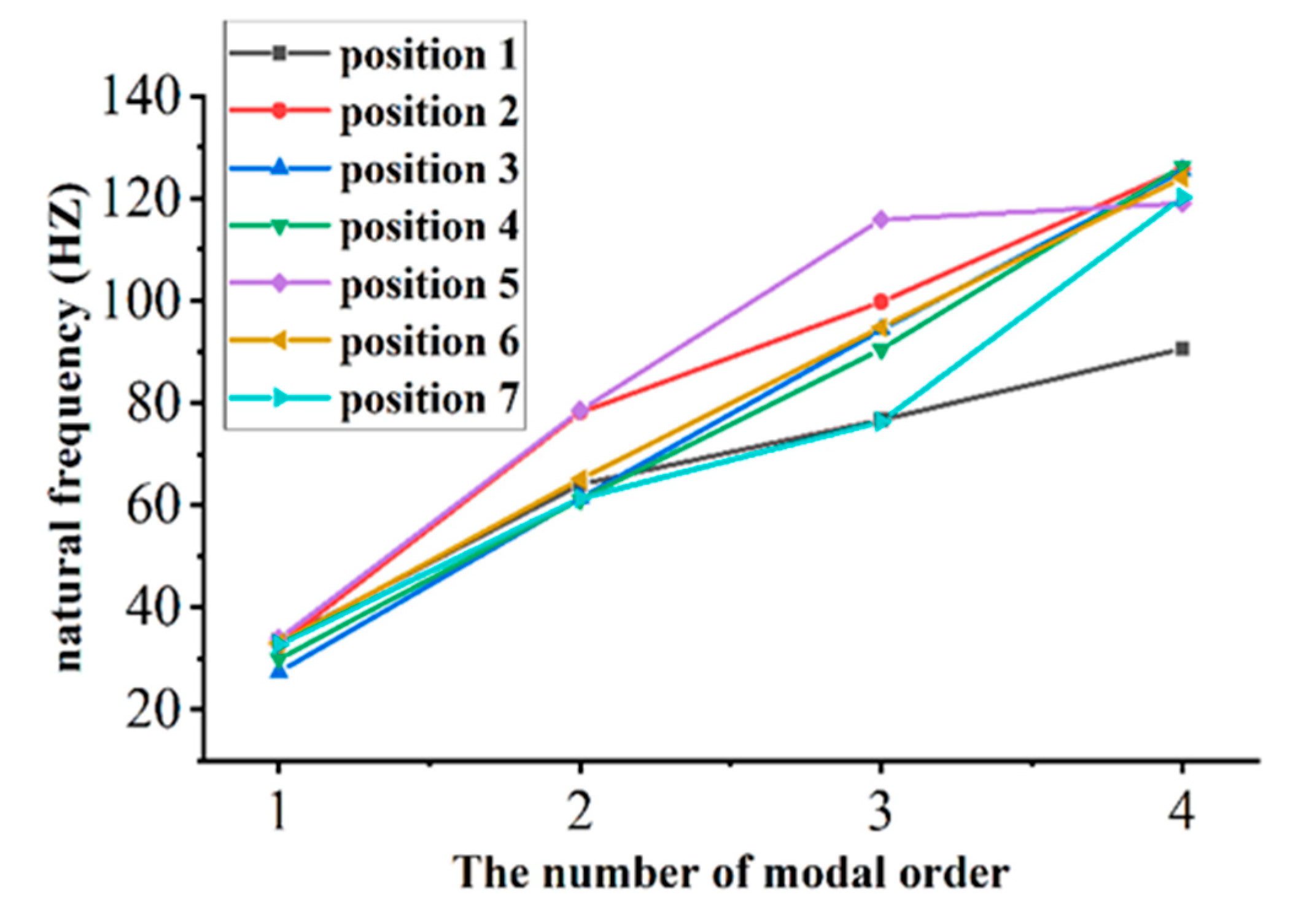
2.1. Modal Analysis of PKM

The natural frequency of the PKM is the basis for the study of its vibration characteristics. The PKM should be avoided from being excited by its natural frequency as far as possible to ensure the stability in the machining process [17]. The FEA method and experimental method are used to analyze the modal. The accuracy of the results is verified by experiments. The vibration equation of PKM can be expressed as
M X ¨ + C X ˙ + K X = F
where M, C and K are the mass matrix, damping matrix and stiffness matrix of the PKM respectively; X, X ˙ and X ¨ are the displacement matrix, velocity matrix and acceleration matrix respectively; F is the external excitation load at the end-effector of the PKM.
The damping and external load of the PKM in Equation (1) are zero when free vibration occurs, so the differential equation of free vibration of the PKM can be expressed as:
M X ¨ + K X = 0
Equation (2) can be solved to obtain the vibration characteristics of the PKM in free vibration state
X = X 0 sin ( ω t + ψ )
where X0 is the vibration amplitude of the PKM response; ω, t and ψ are the response frequency, time and original phase angel, respectively.
Substitute Equation (3) into Equation (2):
K ω 2 M X 0 = 0
Solve the characteristic equation of Equation (4) and obtain n different characteristic values ωi (I = 1~n), which are arranged in ascending order as follows
ω 1 < ω 2 < ω 3 < < ω i < < ω n
where ωi is the ith-order natural frequency of the PKM, which are related to the mass matrix and stiffness matrix.
The external excitation of the PKM in the process of machining is simple harmonic force, which can be express as
F = F 0 cos ω t
where F is the external excitation; F0 is the amplitude of the external excitation.
The response of the PKM to harmonic force can be express as:
X = X 0 sin ( ω t )
Substitute Equations (5) and (6) into Equation (1), and H(ω) represents the Frequency Response Runction (FRF) of the end-effector of the PKM, which is also depending on the position of the PKM:
H ω 1 = ω 2 M + j ω C + K
The PKM used in this paper is a novel 5-DOF hybrid PKM named TriMule, which have been proposed by Tian et al. [18]. As shown in Figure 1, the PKM is composed of a 3-DOF R(2-RPS&RP)&UPS parallel mechanism plus a A/C wrist. Here, R, P, U and S represent revolute, prismatic, universal and spherical joints, respectively, and P denotes an actuated prismatic joint. RPS branch is denoted as limb i (i = 1, 2); UPS branch is denoted as limb 3; and RP branch is denoted as limb 4. It is necessary to simplify the original complex components and establish their own coordinate system to describe the kinematics model of hybrid PKM. wi is defined to represent the direction vector of stretch of limb i. The fixed coordinate system κ is established with the midpoint A4 of the base link as the origin, and the coordinate system κi is established at the intersection of the joint axes of R pair (or U pair) and P pair in limb i. Ri is the attitude matrix of coordinate system κi with respect to fixed coordinate system κ, which can be expressed as:
R i = u i v i w i = cos θ 2 i 0 sin θ 2 i sin θ 1 i sin θ 2 i cos θ 1 i sin θ 1 i cos θ 2 i cos θ 1 i sin θ 2 i sin θ 1 i cos θ 1 i cos θ 2 i
Due to the structural characteristics of the PKM, its dynamic performance is varied with the end-effector position of the PKM. Therefore, seven representative positions are selected in the workspace to analyze the dynamic performance in the coordinate of Om-xmymzm. The origin of the coordinate system Om-xmymzm is established at the intersection of the A/C wrist, and each axis is parallel to each axis of the coordinate system κ. Figure 2 shows the selected representative positions in the workspace. The coordinates of them in the fixed coordinate system κ are shown in Table 1.
The modal simulation of the PKM is carried out by using FEA software on the basis of the above analysis. The positions of the end-effector of the PKM as shown in Table 1 were also selected to analyze. Figure 3 and Figure 4, respectively, gave the first 4 modal modes of the PKM at the initial position (Position 1 in Table 1) and the simulation values of natural frequencies at the 7 representative positions. As shown in Figure 4, the natural frequency of the PKM is strongly correlated with the end-effector position. The higher order modes are relatively more influenced by the end-effector position.

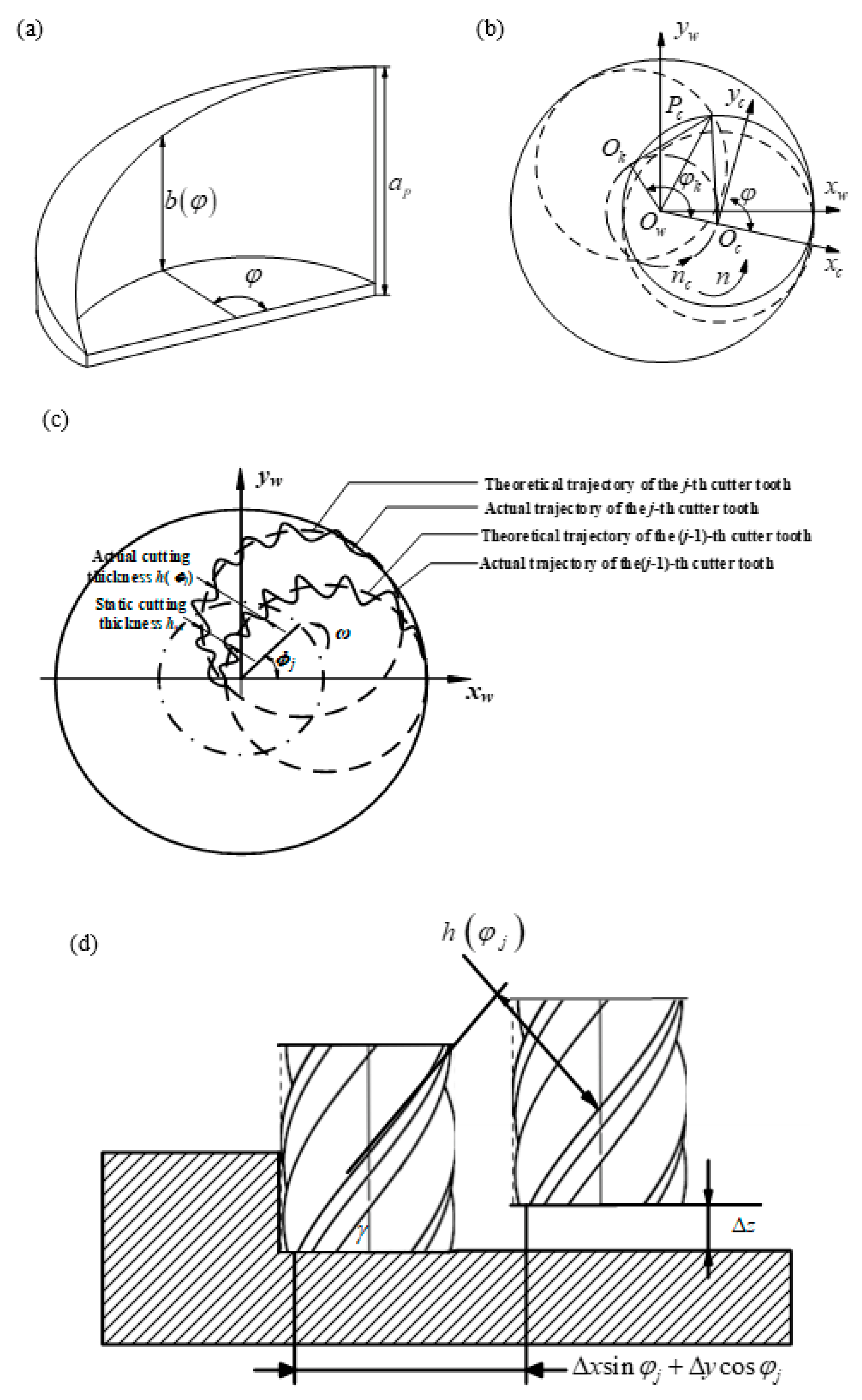
2.2. Cutting Forces Modeling and Identification of Cutting Forces Coefficients of Helical Milling Based on PKM

In order to analyze the 3-DOF cutting stability of helical milling, the cutting forces of the helical milling based on PKM will be established first in this section. Both the side and the bottom edges of the tool are involved in the cutting process. The working state of the side edge can be approximated as an ordinary milling process, while the working state of bottom edge can be approximated as a drilling process. Therefore, the feed motion of helical milling can be divided into two parts, which are axial feed motion vc and circumferential feed motion nc. The feed trajectory is a spiral line, whose radius is the eccentric distance e of the tool and the hole, the pitch is the axial feed ap per revolution, the spindle speed is n, and the number of tool edges is N. The schematic diagram of cutting thickness of helical milling is shown in Figure 5.
The cutting force model of helical milling based on PKM is established according to Literature [8]. According to the cosine theorem, Pc can be expressed as:
P c O w 2 = R t 2 + e 2 2 R t e cos π φ
P c O c = P c O w 2 + e 2 2 P c O w e cos φ k 2
φk can be express as:
φ k = 2 a r cos e R t cos φ e 2 + R t 2 2 R t e cos φ
Therefore, the axial depth of side edge b(φ) in the helical milling can be expressed as:
b φ = a p a p π a r cos e R t cos φ e 2 + R t 2 2 R t e cos φ
kr, kt and ka are the shear effect coefficients of the side edge of tool in radial direction, tangential direction and axial direction in the cutting force model of helical milling, which are the main sources of dynamic cutting force; kre, kte, kae are the friction effect coefficients of side edge of tool in radial direction, tangential direction and axial direction, which are mainly related to static cutting force and can be ignored to analyze the stability; kFea, kFec are the shear effect coefficient and friction effect coefficient of the bottom edge in the axial direction, respectively, which are not related to the dynamic cutting chips and stability of the process. Therefore, only kr, kt and ka are considered in the cutting stability analysis.
As shown in Figure 5, radial, tangential and axial cutting forces in relation to the instantaneous cutting chips thickness during the instantaneous cutting process can be expressed as:
F r j φ = k r b φ j h j φ j F t j φ = k t b φ j h j φ j F a j φ = k a b φ j h j φ j
Neglecting the effect of static cutting forces, which means neglecting the effect of static cutting thickness, the cutting thickness can be expressed as
h φ j = Δ x sin φ j + Δ y cos φ j sin γ Δ z cos γ g φ j
where Δx, Δy and Δz are the displacements generated by two adjacent cutter teeth cutting through the workpiece in each direction. γ is the cutter helix angle and g(φj) is the function indicating whether the cutter teeth are cutting in, which can be expressed as:
g φ j = 1 φ s t < φ j < φ e x   0 φ j < φ s t or   φ j > φ e x  
Therefore, the differentiation of the radial, tangential and axial forces of helical milling can be expressed as:
d F r j d F t j d F a j = b θ k r k t k a sin φ j sin γ cos φ j sin γ cos γ Δ x Δ y Δ z
Converting the Equation (16) into workpiece coordinate system, it can be expressed as:
d F x j d F y j d F z j = sin γ sin φ j cos φ j cos γ sin φ j sin γ cos φ j sin φ j cos γ cos φ j cos γ 0 sin γ d F r j d F t j d F a j
Therefore, the cutting forces can be expressed as:
F = j = 0 N F j
Translating the Equation (18) into matrix form, it can be expressed as
F = A b φ h φ
where A is the direction coefficient matrix, which can be expressed as:
A = h x x t h x y t h x z t h y x t h y y t h y z t h z x t h z y t h z z t
In order to analyze the stability of helical milling based on PKM, the cutting force coefficients need to be identified. According to the method given in the Literature [9], the cutting force coefficients of the side edges are identified by means of slot milling experiments. The average cutting force in each direction in the workpiece coordinate system during slot milling (the entry angle is 0 and the exit angle is π) can be expressed as:
F ¯ w x = 1 4 N k r a p s t + 1 π N k r e a p F ¯ w y = 1 4 N k t a p s t + 1 π N k t e a p F ¯ w z = 1 4 N k a a p s t 1 2 N k a e a p
The cutting force coefficient can be identified by linear regression method according to Equation (21).

2.3. 3-DOF Cutting Stability Analysis of Helical Milling Based on the PKM

The improved Semi-Discrete Time Domain Method is used to analyze the cutting stability of titanium alloy helical milling at 7 positions of TriMule. The differential equations of 3-DOF cutting dynamics for helical milling of TriMule can be expressed as
x ¨ y ¨ z ¨ + 2 ω n x ω n y ω n z ξ x ξ y ξ z x ˙ y ˙ z ˙ + ω n x 2 ω n y 2 ω n z 2 + Q x y z = Q x t τ y t τ z t τ
Q = a p h x x t m t x a p h x y t m t x a p h x z t m t x a p h y x t m t y a p h y y t m t y a p h y z t m t y a p h z x t m t z a p h z y t m t z a p h z z t m t z
where ωnx, ωny and ωnz are the angular natural frequency of the PKM in the direction of x, y and z respectively; mtx, mty and mtz are the modal mass of the PKM in the direction of x, y and z respectively; and ξx, ξy and ξz are the damping ratio. x(t − τ) is the time delay due to the regeneration effect, which is equal to the time between the cutter teeth cutting into and cutting out the workpiece. T is the time delay of ordinary cutter with equal pitch. Since the revolution speed nc is far less than the spindle speed n, T can be expressed as:
T = 60 N n
Transforming kinematics equation into state space equation
u ˙ t = A i u t + ω a B i u i m + 1 + ω b B i u i m
where Ai is the constant matrix; Bi is the state term; ui is the space term. As the time delay is equal to the period, ωa = ωb = 1/2. m is the integer introduced:
m = int τ + Δ t / 2 Δ t
The dynamic equation of regenerative cutting can be expressed as:
u i + 1 = P i u i + ω a R i u i m + 1 + ω b R i u i m
P i = exp A i Δ t
R i = exp A i Δ t I A i 1 B i
I represents the identity matrix; (3m + 6) dimensional state vector can be expressed as:
z i = c o l x i y i z i x ˙ i y ˙ i z ˙ i x i 1 y i 1 z i 1 x i m y i m z i m
Thus, the following mapping can be constructed
z i + 1 = D i z i
where Di is the (3m + 6) dimensional coefficient matrix, which can be expressed as:
D i = P i 11 P i 12 P i 13 P i 14 P i 15 P i 16 0 0 R i 11 2 R i 12 2 R i 13 2 R i 11 2 R i 12 2 R i 13 2 P i 61 P i 62 P i 63 P i 64 P i 65 P i 66 0 0 R i 61 2 R i 62 2 R i 63 2 R i 61 2 R i 62 2 R i 63 2 1 0 0 0 0 0 0 0 0 0 0 0 0 0 0 1 0 0 0 0 0 0 0 0 0 0 0 0 0 0 1 0 0 0 0 0 0 0 0 0 0 0 0 0 0 0 0 0 1 0 0 0 0 0 0 0 0 0 0 0 0 0 0 1 0 0 0 0 0 0 0 0 0 0 0 0 0 0 1 0 0 0 0 0 0 0 0 0 0 0 0 0 0 1 0 0 0 0 0 0 0 0 0 0 0 0 0 0 1 0 0 0 .  
The state-transition matrix Φ can be expressed as:
Φ = D k 1 D k 2 D 1 D 0
According to Floquent Theory, indicating that the matrix converges, the variation of dynamic cutting thickness has an upper limit when the eigenvalue of the state transition matrix is less than 1. The process of the PKM helical milling is in a stable state. Otherwise, the cutting process is unstable.

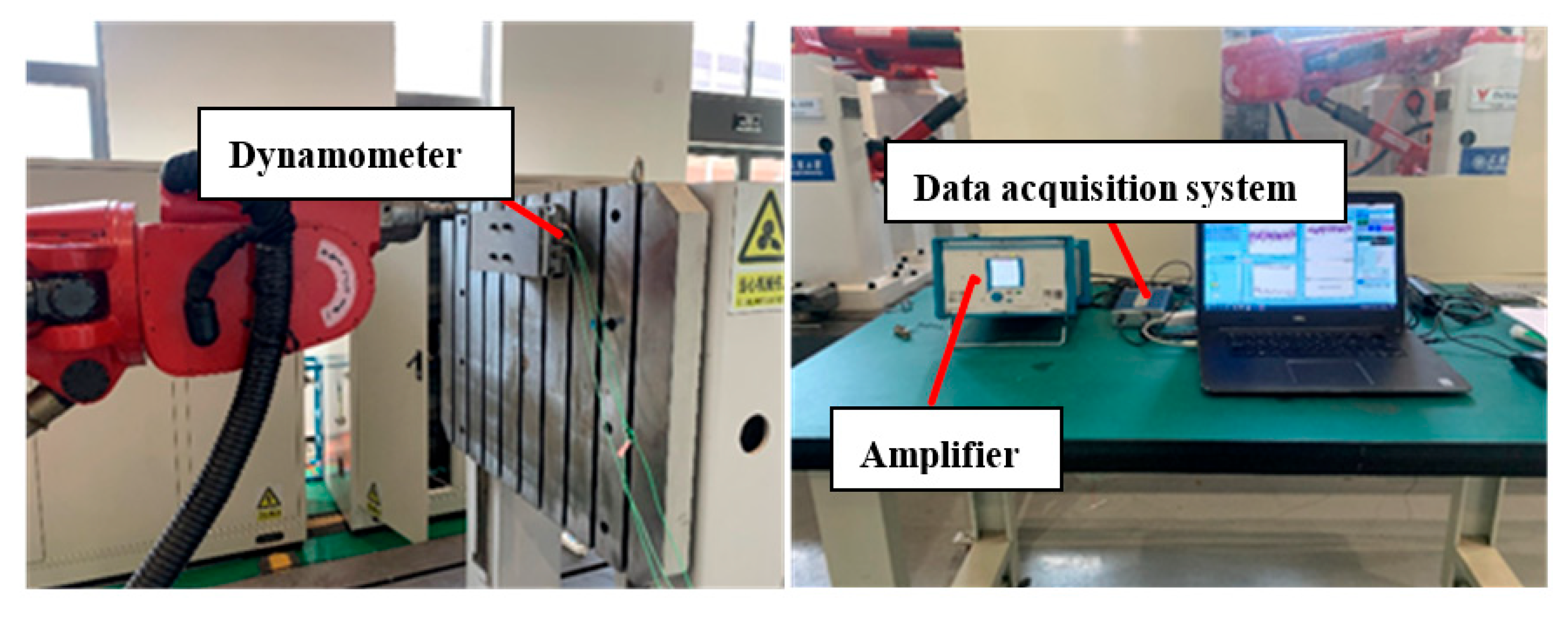
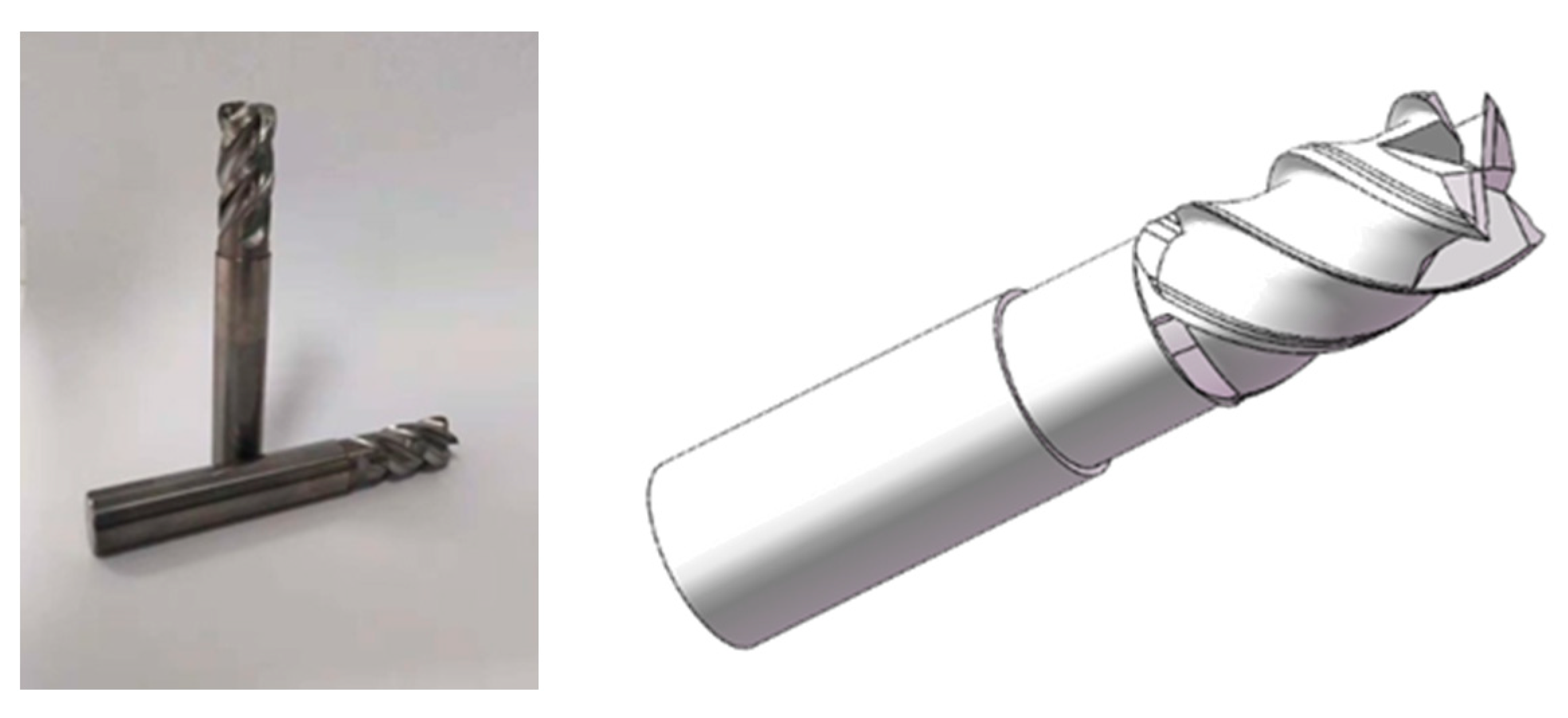
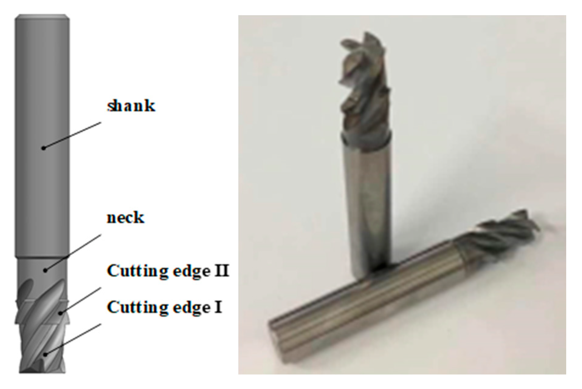
3. Experimental Platform Set-Up

3.1. Cutting Force Coefficients Identification and Stability Verification

Before analyzing the cutting stability of helical milling based on PKM, it is necessary to model the cutting forces when it is applied to helical milling. The cutting force model of titanium alloy helical milling based on TriMule is established by taking titanium alloy commonly used in aircraft industry as an example in this paper, as shown in Figure 6. Specific modeling methods and experimental methods have been introduced in detail in Literature [8]. In this paper, the angle of A/C wrist is adjusted to 0, and the cutting force coefficients can be identified from the platform.
As shown in Figure 6, a Kistler three-direction dynamometer (9257A) with supporting charge amplifier (type 5070), and data acquisition system and Kistler software were utilized for the cutting force measurement. The workpiece material used in this paper is titanium alloy Ti6Al4V, the physical and mechanical properties of which are shown in Table 2 [19]. The diameter of the helical milling holes in this paper is 19.05 mm, and the carbide helical milling tool with a 12 mm diameter was selected for the helical milling tests. According to the selected tool diameter and the cutting conditions of titanium alloy, the spindle speed of 2000 rpm is selected to identify the cutting force parameters in order to control the tool wear during machining [20,21]. The helical milling tool is shown in Figure 7, and details about cutting tool are listed in Table 3. Cutting experiments were performed on the experimental platform according to the cutting experimental parameters shown in Table 4, and the cutting forces coefficients were identified.
In order to verify the correctness of the stability prediction model of titanium alloy helical milling based on PKM, Position 1 and Position 2 shown in Table 1 are used as the validation positions considering the structural characteristics of the parallel mechanism. Since the change of spindle speed has little effect on the cutting force parameters and can be ignored, the cutting force parameters obtained at the spindle speed of 2000 rpm are used for stability verification experiments [22,23,24]. The cutting parameters shown in Table 5 are used for the machining experiments.
As the analysis mentioned above, a step-cutter is proposed to reduce the radial cutting depth to improve the stability of helical milling and optimize the machining quality.
The step-cutter is improved the main structure of the helical milling cutter which includes two parts of cutting edge, neck part and shank. The height difference between the two parts of the cutting edge is 1mm. Right-angle transition mode is adopted to reduce impact. The necking part prevents cutting edge of the second part from cutting the surface again. The cutter material is cemented carbide. The cutter structure is shown in Figure 8. The parameters of the cutter are shown in Table 6.

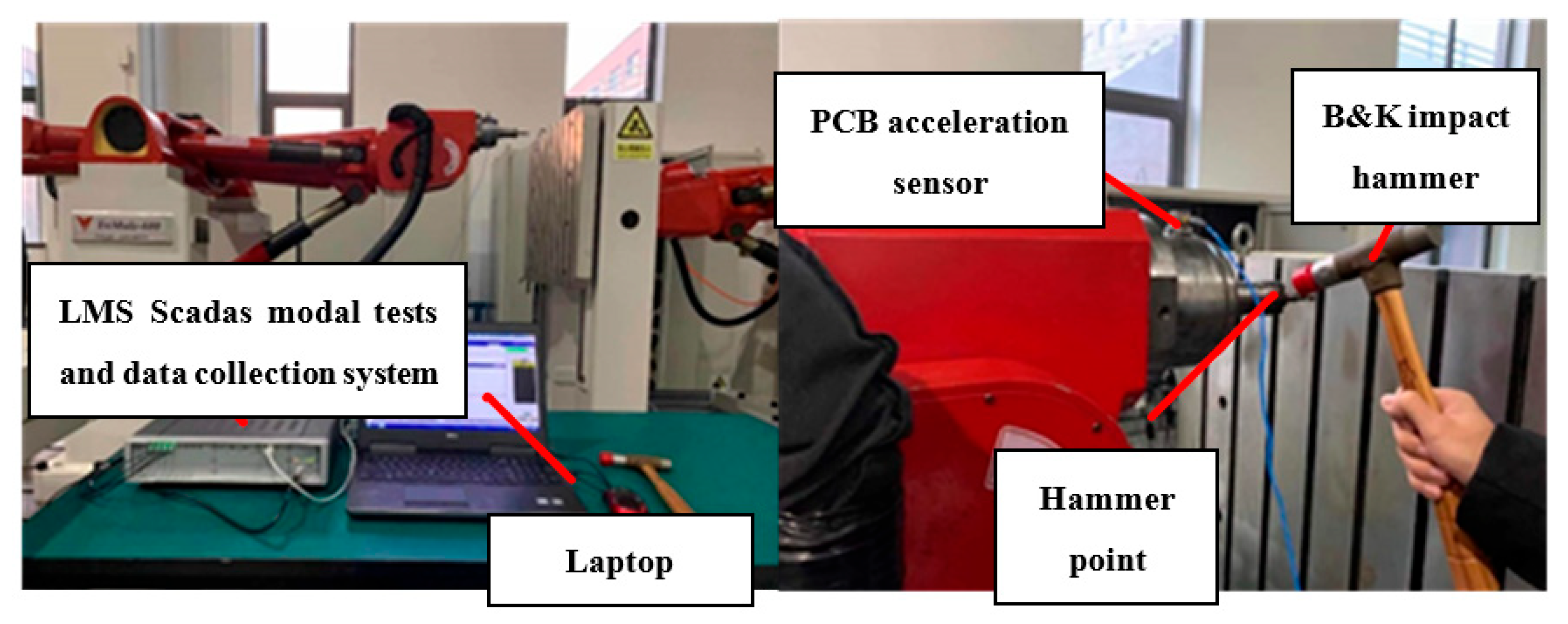
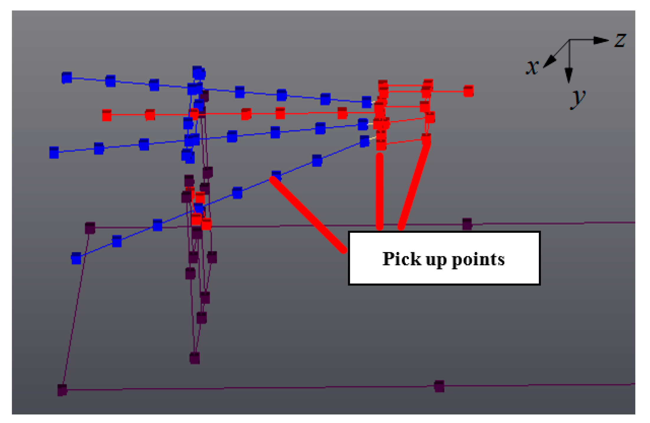
3.2. Experimental Platform Set-Up to Indentify of Modal Parameters of TriMule

In order to verify the correctness of modal simulation, modal experiments are carried out on the 7 positions in Table 1 respectively by hammering experiment. The specific experimental methods and equipment have been described in detail in Literature [8]. The angle of A/C wrist of the PKM change to 0 this time, and the point-line model for hammering tests is re-established. Table 7 shows the modal parameters of the first 4 modes of the PKM. The experimental platform of TriMule helical milling modal tests is presented in Figure 9. The B&K impact hammer and PCB acceleration sensor were used to shock excitation and pick up the generated vibration signals. The input and output signals are processed through the data collection system of LMS, and the modal data processing is imported into the analysis software. In this paper, the modal tests are carried out by single point impact and single point vibration signal pickup method. As TriMule is a complex high-order system, multiple vibration pickup points were arranged, as shown in Figure 10. At the same time, the impact hammer strikes along different directions of each impact point. In order to reduce the random measurement error, the vibration measurement tests for every pickup point repeat five times. Taking the initial position as an example, the modal parameters of the PKM at this position are obtained as shown in Table 5. Figure 11 shows the variation of natural frequency of the PKM with different position in x, y and z directions to facility the analysis of variation of modal parameters with the configuration of the PKM.
As shown in Figure 11, comparing Position 1 and Position 2 and Position 3, the 1st order natural frequency decreased gradually with the positive deviation of position along the x-axis. The bigger the offset is, the more decreased it is. Furthermore, the 3rd order and 4th order natural frequency from the Position 1 to Position 2 are risen sharply, and from the Position 2 to Position 3 are changed slightly. Comparing Position 1, Position 4 and Position 5, the 1st order natural frequency varies slightly along the z-axis. The 2nd, 3rd and 4th order natural frequencies all increase along the z-axis, and the fourth order natural frequencies increase most obviously. Comparing Position 1, Position 6 and Position 7, the natural frequencies of the first two orders are basically unchanged along the y-axis, while the natural frequencies of the 3rd and 4th orders increase significantly with the change of the y-axis. Therefore, it can be found that the 1st order natural frequency variation range is the lowest with the position variation. The value of 1st natural frequency decreases at most 18.4% from the initial position. While the 3rd and 4th orders natural frequency vary at most 51.2% from the initial position, which increases the most.

4. Results and Discussion

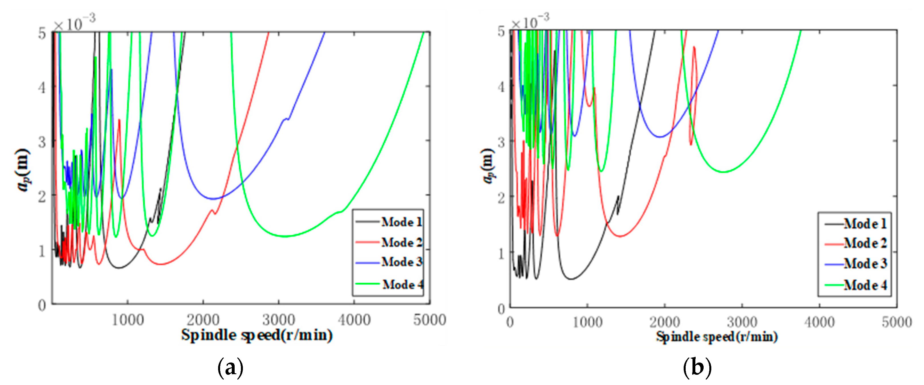
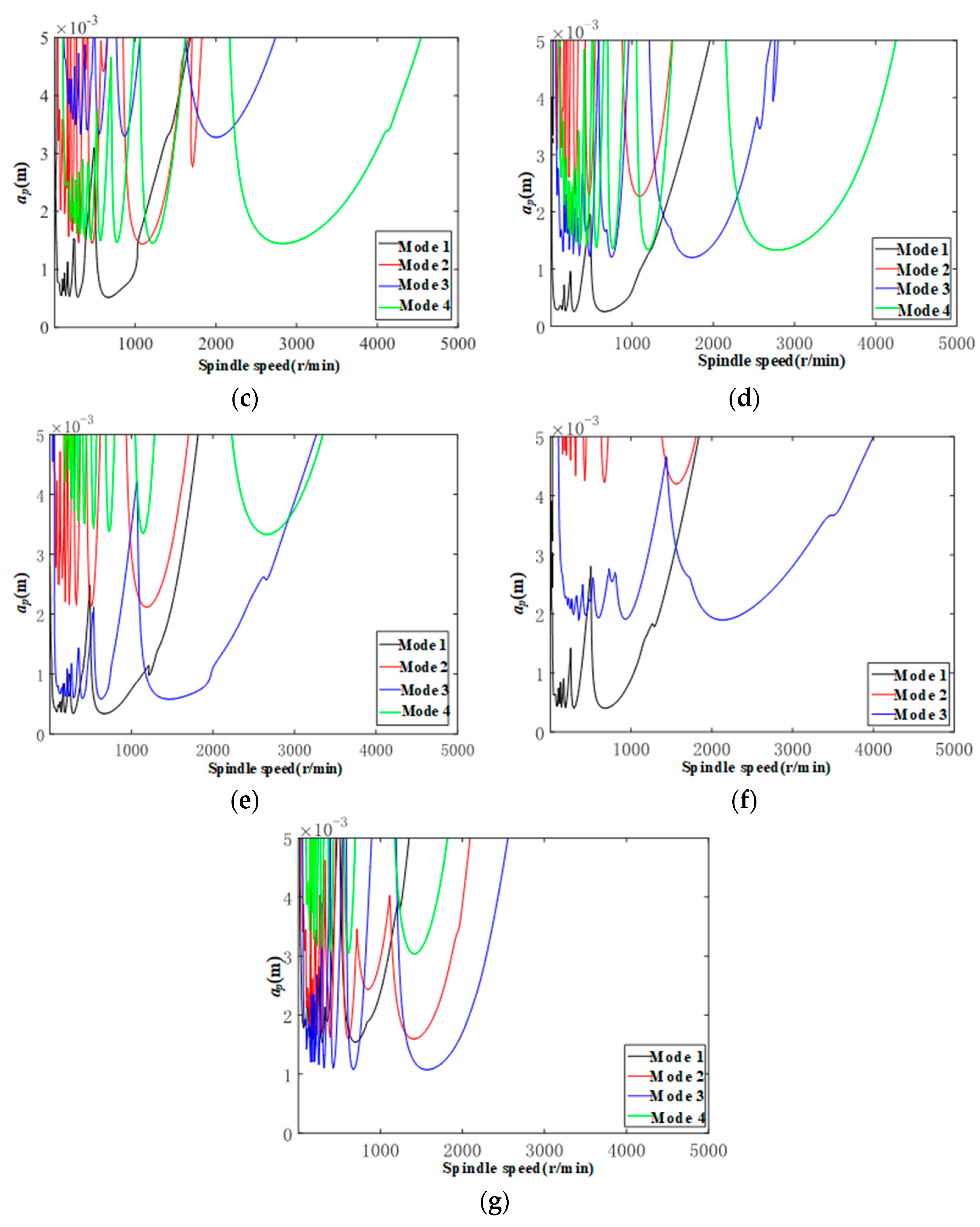
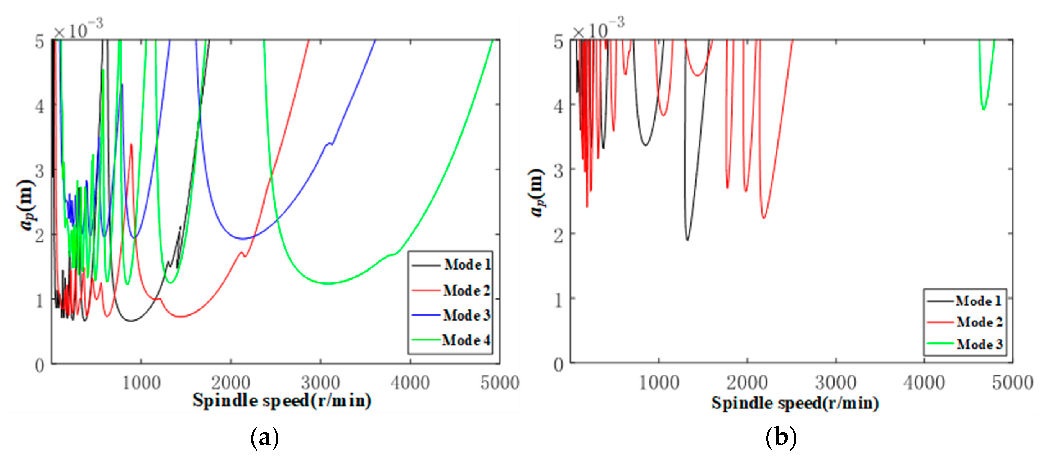
4.1. Cutting Stability Lobes of Titanium Alloy Helical Milling Based TriMule

According to the experimental platform established in Section 3, the cutting force coefficients of the PKM-based titanium alloy helical milling hole were identified and obtained, as shown in Table 8.
In addition, hammering modal tests are performed on the TirMule based on the established experimental platform. Due to the structural characteristics of the PKM, the modal parameters are strongly position-dependent. Therefore, modal tests are conducted for each of the 7 positions shown in Table 1, and the stability domain of the TriMule-based titanium alloy helical milling is analyzed by combining the identified modal parameters and cutting force coefficients.
According to the above analysis, the stability lobes of TriMule at 7 positions are drawn, as shown in Figure 12. The stability of other poses under the spindle speed of 1000 r/min is roughly determined by the 1st mode except Position 6 and 7. By comparing Position 1 and Position 2 and 3, the stability domain of the working condition above 2000 r/min increases significantly when the coordinate of end-effector deviation along x direction, and this variation is mainly affected by the 4th mode. When the deviation continues to 400 mm, the stability domain will decrease again. By comparing Position 1 and Position 4 and 5, the stability domain of the PKM decreases slightly at low spindle speed when the end-effector extends 100 mm forward along the z-axis, while the stability domain at high spindle speed has no significant change, which is mainly affected by the 4th mode. However, the end-effector retracted 50 mm along the z-axis will make the stability domain at high spindle speed significantly increase, which is mainly affected by the 3rd mode. By comparing Position 1 and Postion 6 and 7, the stability domain is mainly affected by the 1st and 3rd order modes after it is moved along the y-axis, and the rise of 100 mm along the y-axis will greatly improve the stability region at low spindle speed.

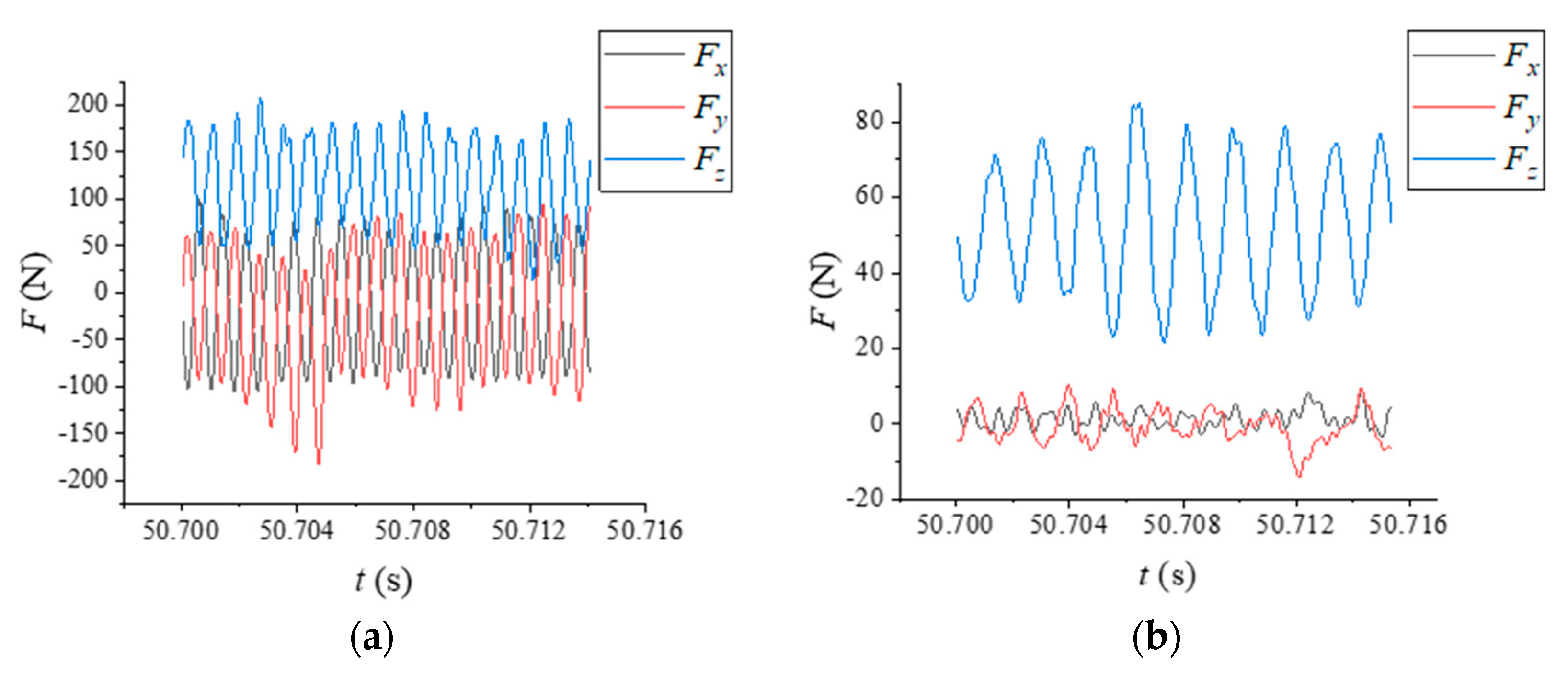
4.2. Validation of Cutting Stability Lobes of TriMule Based Titanium Alloy Helical Milling

It is necessary to verify the correctness of stability lobes of helical milling based TriMule. The acceleration signals in the machining process are collected to time-frequency transformation to determine whether the machining process was unstable. As mentioned in Section 3.1, the correctness of the obtained stability lobes is verified, with Position 1 and Position 2 as examples. The combination of cutting parameters is shown in Table 7. The spectrum of experimental acceleration signal is shown in Figure 13.
As shown in Figure 13, when the spindle speed is 1000 r/min and the axial feed is 0.8 mm, the helical milling of TriMule at Position 1 and Position 2 has a small vibration, and the machining stability is good under other processing parameters. It can be seen that the predicted results are in agreement with the experimental results. In addition, at Position 1, the main components of the acceleration signal spectrum are the passing frequency of the cutter tooth, and its frequency doubling when the spindle speed is 1000 r/min and the axial feed is 0.2 mm per revolution. It can be judged that no instability occurs in the milling process. When the axial feed is increased in the same position, it can be seen that vibration with a different amplitude occurs in the high frequency band of the acceleration signal spectrum in the three directions, and the vibration in the z direction is the most obvious. Therefore, it can be judged that instability occurs. At Position 2, when the rotational speed is 1000 r/min, with the increase of axial feed per revolution, the unstable frequency 1247 Hz of acceleration signal in frequency domain is significant, which will obviously affect the milling accuracy.
In addition, the cutting stability will also affect the roughness condition of the inner wall of the hole. Therefore, in verifying the correctness of the above stability leaflet diagram, the inner wall roughness of titanium alloy helical milling holes at different positions of TriMule is measured by the roughness measuring instrument. The results are shown in Figure 14 and Figure 15.
As shown in Figure 14, the overall surface roughness increases with the axial feed per revolution increases. This is because the increase of axial feed leads to the increase of spiral feed track pitch, which makes the machining traces on the processed surface more serious, alongside the increase of roughness.
The comparison of the surface roughness of helical milling holes at Position 1 and 2 at each spindle speed shows Figure 15. It can be seen that when the axial feed per revolution is small (less than 0.4 mm), the surface roughness of holes at Position 2 is smaller and the machining quality is better. When the axial feed per revolution is larger (greater than 0.4 mm), the surface roughness of holes at position 1 of is smaller and the machining quality is better.

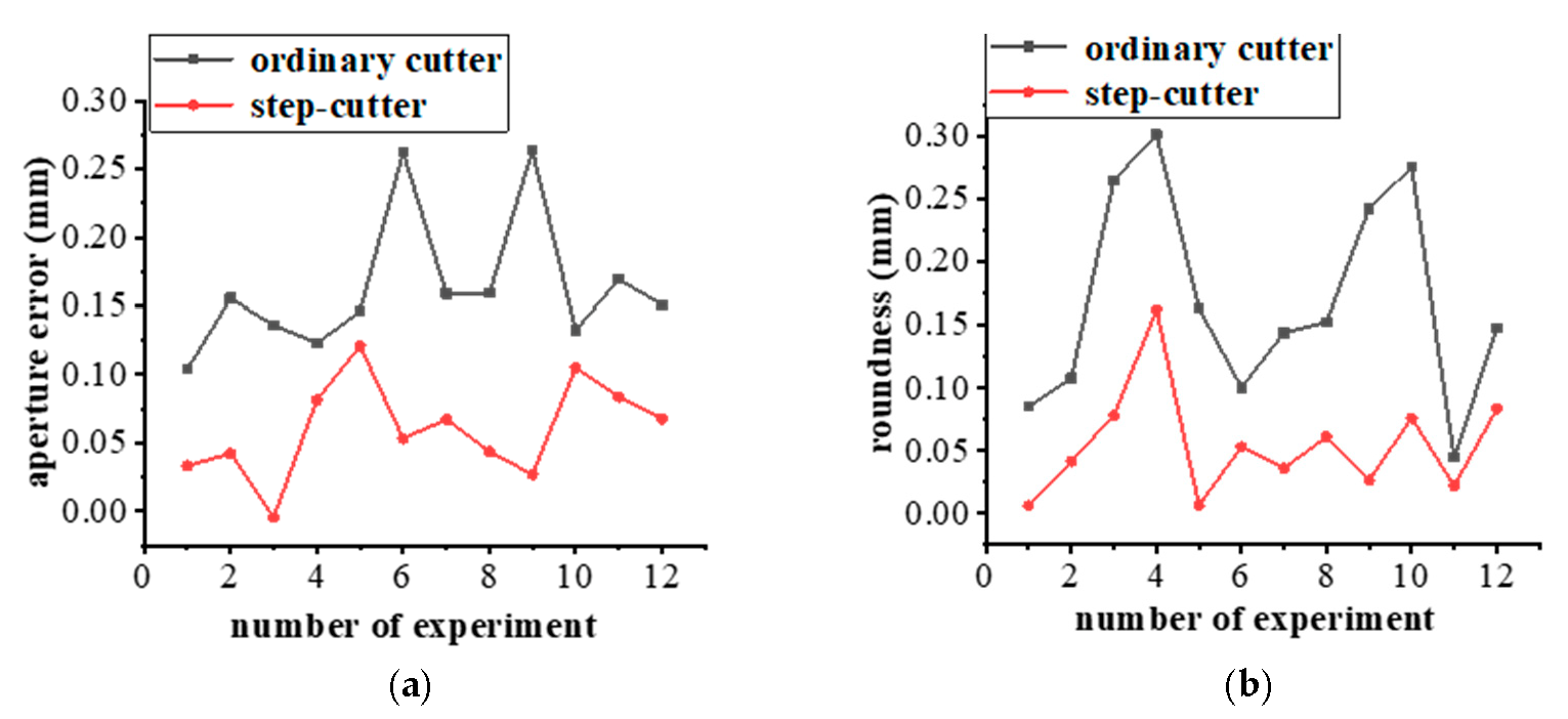
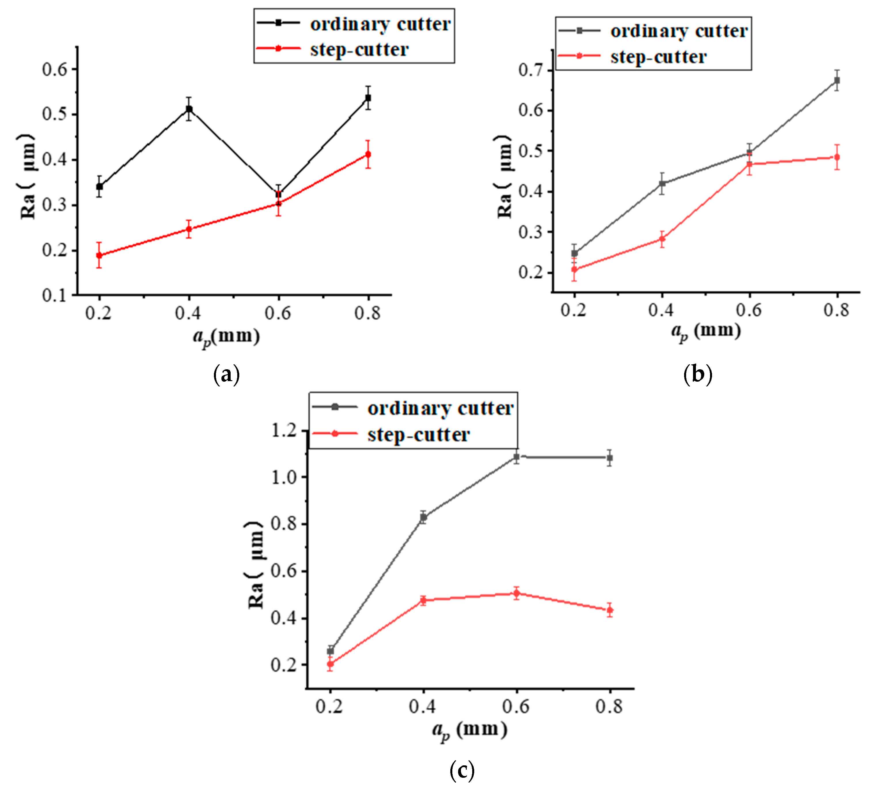
4.3. Optimization of Cutting Stability Lobes of Titanium Alloy Helical Milling Based TriMule

The influence of machining instability on machining quality can be reduced by optimizing the cutter. Since the dynamic cutting force that causes the milling instability is from the side edge of the tool, and the radial cutting depth of the side edge will directly affect the cutting force and continuous cutting time of the tool, the use of step-cutters can significantly reduce the radial cutting force to increase the cutting stability domain and reduce the cutting instability.
The ratio d of the radial cut depth to the tool diameter is used as a variable to optimize the cutting stability, which are set as 0.8, 0.6, 0.4 and 0.2, respectively. Taking TriMule at initial position as an example, the cutting stability of different radial cutting depths is shown in Figure 16. As shown in the Figure 16, when d decreases from 1 to 0.4, the limit cutting depth of the stability region increases slightly. When d decreases from 0.4 to 0.2, the ultimate cutting depth in the stability region has also increased, but the increase is small relative to the case where d decreases from 1 to 0.4.
The stability lobe diagrams of TriMule at the initial position with the ordinary helical milling cutter and the step-cutter were drawn respectively in Figure 17, and the cutting forces are collected in Figure 18. As shown in Figure 17 and Figure 18, step-cutters significantly increase the cutting stability domain and reduce cutting forces. Furthermore, the decrease of the period over the same time is conducive to reducing the excitation of the cutter.
The aperture and roundness of the hole containing ordinary and step-cutters to characterize the precision of the milling hole. Figure 19 is shown the accuracy comparison of helical milling hole between ordinary cutter and step-cutter. By comparing the machining accuracy of helical milling with an ordinary cutter and a step-cutter, it can be concluded that the step-cutter can effectively reduce the aperture error under various parameter combinations. When the cutting depth is 0.4 mm and 0.6 mm with the spindle speed of 3000 r/min, the optimization effect is most obvious. The average aperture error decreased by 63.2%. The step-cutter can also effectively reduce the roundness error—particularly in the condition of large cutting depth and low spindle speed, the roundness error optimization is the most obvious. The average roundness error is reduced by 67.7%.
In order to verify that the step-cutter can effectively improve the quality of the machined surface, the roughness of the inner wall of the hole at different rotational speeds at the same location was measured using a roughness measuring instrument and compared with the roughness of the inner wall of the hole diameter machined with an ordinary cutter, as shown in Figure 20.
As shown in Figure 20, the surface roughness of helical milling holes is compared between an ordinary cutter and step-cutter at different spindle speeds. It can be found that with the increase of spindle speed, the optimization of step-cutter for surface roughness becomes more obvious. In addition, it can be seen from Figure 20c that the surface processed by step-cutter avoids the dramatic increase in roughness with the increase of axial feed per revolution, and still maintains good reliability. This is because the step-cutter can reduce the cutting force and increase the period of cutting force. The larger the machining parameters are, the greater the cutting force is, and the more obvious the optimization of step-cutter is. The surface roughness of titanium alloy helical milling hole is reduced by 30.7% on average.

5. Conclusions

The FEA software is used to analyze the variation of the static stiffness of the end-effector of the PKM at different positions. The cutting force model of titanium alloy helical milling based PKM is established, and the cutting force coefficients are identified. The static stiffness at the initial position is obviously better than that at other positions. The modal parameters and vibration modes of the PKM under different positions are obtained by simulation and hammer tests. The 1st order natural frequency is least affected by position, while the 3rd order natural frequency is most affected. A 3-DOF prediction model for the stability in helical milling based on the PKM is established, and the stability lobe diagram of seven positions and poses is obtained. The influence of position on stability region is analyzed. In order to reduce the influence of cutting instability on the machining quality, the machining process is optimized by using step-cutters. The step-cutter can significantly reduce the aperture error (63.2%), roundness (67.7%) and surface roughness (30.7%). The study of the stability of helical milling on titanium alloy provided a basis for further optimization of machining technology in the future.

Author Contributions

Conceptualization, M.S. and Z.H.; methodology, M.S.; software, Z.H.; validation, S.L., H.L. (Hao Li) and X.Q.; formal analysis, S.L.; investigation, M.S.; resources, X.Q.; data curation, S.L.; writing—original draft preparation, M.S.; writing—review and editing, Z.H.; visualization, H.L. (Hao Li); supervision, H.L. (Haitao Liu); project administration, X.Q.; and funding acquisition, X.Q., S.L. and H.L. (Hao Li). All authors have read and agreed to the published version of the manuscript.

Funding

This research was funded by National Natural Science Foundation of China (Grant numbers: 51775373 and 52075380), and Natural Science Foundation of Tianjin (Grant number: 19JCYBJC19000).

Institutional Review Board Statement

Not applicable.

Informed Consent Statement

Not applicable.

Data Availability Statement

Not applicable.

Conflicts of Interest

The authors declare no conflict of interest.

References

  1. Mohd Yusuf, S.; Cutler, S.; Gao, N. Review: The Impact of Metal Additive Manufacturing on the Aerospace Industry. Metals 2019, 9, 1286. [Google Scholar] [CrossRef] [Green Version]
  2. Pereira, R.B.D.; Brandão, L.C.; de Paiva, A.P.; Ferreira, J.R.; Davim, J.P. A review of helical milling process. Int. J. Mach. Tools Manuf. 2017, 120, 27–48. [Google Scholar] [CrossRef]
  3. Altintas, Y.; Brecher, C.; Weck, M.; Witt, S. Virtual Machine Tool. CIRP Ann. 2005, 54, 115–138. [Google Scholar] [CrossRef]
  4. Piras, G.; Cleghorn, W.L.; Mills, J.K. Dynamic finite-element analysis of a planar high-speed, high-precision parallel manipulator with flexible links. Mech. Mach. Theory 2005, 40, 849–862. [Google Scholar] [CrossRef]
  5. Luo, H.-w.; Wang, H.; Zhang, J.; Li, Q. Rapid Evaluation for Position-Dependent Dynamics of a 3-DOF PKM Module. Adv. Mech. Eng. 2015, 6, 326–334. [Google Scholar] [CrossRef]
  6. Law, M.; Ihlenfeldt, S.; Wabner, M.; Altintas, Y.; Neugebauer, R. Position-dependent dynamics and stability of serial-parallel kinematic machines. CIRP Ann. 2013, 62, 375–378. [Google Scholar] [CrossRef]
  7. Mousavi, S.; Gagnol, V.; Bouzgarrou, B.C.; Ray, P. Dynamic modeling and stability prediction in robotic machining. Int. J. Adv. Manuf. Technol. 2016, 88, 3053–3065. [Google Scholar] [CrossRef]
  8. Li, J.; Li, B.; Shen, N.; Qian, H.; Guo, Z. Effect of the cutter path and the workpiece clamping position on the stability of the robotic milling system. Int. J. Adv. Manuf. Technol. 2016, 89, 2919–2933. [Google Scholar] [CrossRef]
  9. Shi, M.; Qin, X.; Li, H.; Shang, S.; Jin, Y.; Huang, T. Cutting force and chatter stability analysis for PKM-based helical milling operation. Int. J. Adv. Manuf. Technol. 2020, 111, 3207–3224. [Google Scholar] [CrossRef]
  10. Cao, H.; Zhou, K.; Chen, X. Stability-based selection of cutting parameters to increase material removal rate in high-speed machining process. Proc. Inst. Mech. Eng. Part B J. Eng. Manuf. 2015, 230, 227–240. [Google Scholar] [CrossRef]
  11. Mejri, S.; Gagnol, V.; Le, T.-P.; Sabourin, L.; Ray, P.; Paultre, P. Dynamic characterization of machining robot and stability analysis. Int. J. Adv. Manuf. Technol. 2015, 82, 351–359. [Google Scholar] [CrossRef]
  12. Polini, W.; Turchetta, S. Cutting force, tool life and surface integrity in milling of titanium alloy Ti-6Al-4V with coated carbide tools. Proc. Inst. Mech. Eng. Part B J. Eng. Manuf. 2014, 230, 694–700. [Google Scholar] [CrossRef]
  13. Zain, A.M.; Haron, H.; Sharif, S. Application of GA to optimize cutting conditions for minimizing surface roughness in end milling machining process. Expert Syst. Appl. 2010, 37, 4650–4659. [Google Scholar] [CrossRef]
  14. Muñoz-Escalona, P.; Maropoulos, P.G. A geometrical model for surface roughness prediction when face milling Al 7075-T7351 with square insert tools. J. Manuf. Syst. 2015, 36, 216–223. [Google Scholar] [CrossRef] [Green Version]
  15. Liu, H.; Sun, Y.; Geng, Y.; Shan, D. Experimental research of milling force and surface quality for TC4 titanium alloy of micro-milling. Int. J. Adv. Manuf. Technol. 2015, 79, 705–716. [Google Scholar] [CrossRef]
  16. Zhang, R.; Li, A.; Song, X. Surface quality adjustment and controlling mechanism of machined surface layer in two-step milling of titanium alloy. Int. J. Adv. Manuf. Technol. 2022, 119, 2691–2707. [Google Scholar] [CrossRef]
  17. Chen, C.; Peng, F.; Yan, R.; Tang, X.; Li, Y.; Fan, Z. Rapid prediction of posture-dependent FRF of the tool tip in robotic milling. Robot. Comput.-Integr. Manuf. 2020, 64. [Google Scholar] [CrossRef]
  18. Huang, T.; Dong, C.; Liu, H. Five-Degree-of-Freedom Parallel Robot with Multi-Shaft Rotary Brackets. Patent No. WO/2017/005015, 1 December 2017. [Google Scholar]
  19. Wang, H.; Qin, X.; Ren, C.; Wang, Q. Prediction of cutting forces in helical milling process. Int. J. Adv. Manuf. Technol. 2011, 58, 849–859. [Google Scholar] [CrossRef]
  20. Guimu, Z.; Chao, Y.; Chen, S.R.; Libao, A. Experimental study on the milling of thin parts of titanium alloy (TC4). J. Mater. Process. Technol. 2003, 138, 489–493. [Google Scholar] [CrossRef]
  21. Kao, Y.-C.; Nguyen, N.-T.; Chen, M.-S.; Su, S.-T. A prediction method of cutting force coefficients with helix angle of flat-end cutter and its application in a virtual three-axis milling simulation system. Int. J. Adv. Manuf. Technol. 2014, 77, 1793–1809. [Google Scholar] [CrossRef]
  22. Peng, C.; Wang, L.; Liao, T.W. A new method for the prediction of chatter stability lobes based on dynamic cutting force simulation model and support vector machine. J. Sound Vib. 2015, 354, 118–131. [Google Scholar] [CrossRef]
  23. Yang, Y.; Liu, Q.; Zhang, B. Three-dimensional chatter stability prediction of milling based on the linear and exponential cutting force model. Int. J. Adv. Manuf. Technol. 2014, 72, 1175–1185. [Google Scholar] [CrossRef]
  24. Yi, J.; Chen, K.; Xu, Y. Microstructure, Properties, and Titanium Cutting Performance of AlTiN–Cu and AlTiN–Ni Coatings. Coatings 2019, 9, 818. [Google Scholar] [CrossRef] [Green Version]
Figure 1. The PKM named TriMule: (a) CAD model (b) structure diagram with coordinates of TriMule.
Machines 10 00404 g001
Figure 2. Seven representative positions in the workspace of TriMule.
Machines 10 00404 g002
Figure 3. The mode shapes of the first 4 order simulation modes of the PKM at initial position. (a) 1st mode shape of vibration; (b) 2nd mode shape of vibration; (c) 3rd mode shape of vibration; and (d) 4th mode shape of vibration.
Machines 10 00404 g003
Figure 4. The natural frequency simulation values of the PKM at position 7.
Machines 10 00404 g004
Figure 5. The schematic diagram of cutting thickness of helical milling: (a) the chip of helical milling; (b) the process of helical milling (top view); (c) dynamic cutting thickness of the j-th cutter tooth in the xw direction and yw direction of helical milling; and (d) dynamic cutting thickness of the j-th cutter tooth in the zw direction.
Machines 10 00404 g005
Figure 6. Experimental platform for cutting forces coefficients in TriMule based helical milling.
Machines 10 00404 g006
Figure 7. Helical milling tool and its 3D model.
Machines 10 00404 g007
Figure 8. The structure of step-cutter.
Machines 10 00404 g008
Figure 9. Experimental platform of TriMule based helical milling modal tests.
Machines 10 00404 g009
Figure 10. Arrangement of vibration pickup points on TriMule modal test.
Machines 10 00404 g010
Figure 11. The first 4 order natural frequencies of the PKM in different positions. (a) Natural frequency in the x direction; (b) Natural frequency in the z direction; (c) Natural frequency in the y direction.
Machines 10 00404 g011
Figure 12. Stability lobes of helical milling based TriMule in 7 Positions. (a) Position 1; (b) Position 2; (c) Position 3; (d) Position 4; (e) Position 5; (f) Position 6; and (g) Position 7.
Machines 10 00404 g012aMachines 10 00404 g012b
Figure 13. Spectrum of experimental acceleration signal. (a) Signal spectrum of acceleration along x, y and z under Position 1 (cutting parameter combine 1); (b) Signal spectrum of acceleration along x, y and z under Position 1 (cutting parameter combine 10); (c) Signal spectrum of acceleration along x, y and z under Position 2 (cutting parameter combine 1); and (d) Signal spectrum of acceleration along x, y and z under Position 2 (cutting parameter combine 10).
Machines 10 00404 g013
Figure 14. Surface roughness of helical milling hole with different processing parameters of TriMule. (a) Position 1; (b) Position 2; (c) Position 3; and (d) Position 4.
Machines 10 00404 g014
Figure 15. Surface roughness comparison of Position 1 and Position 2 at different spindle speeds. (a) n = 1000 r/min; (b) n = 2000 r/min; and (c) n = 3000 r/min.
Machines 10 00404 g015
Figure 16. Stable lobe of TriMule with different radial cutting depths at Position 1. (a) d = 0.8. (b) d = 0.6. (c) d = 0.4. (d) d = 0.2.
Machines 10 00404 g016
Figure 17. Stability lobes of initial position for ordinary helical milling cutter and step-cutter. (a) Ordinary helical milling cutter. (b) Step-cutter.
Machines 10 00404 g017
Figure 18. Cutting force of ordinary and step-cutter (Position 1, n = 1000 r/min, ap = 0.2 mm). (a) Ordinary helical milling cutter. (b) Step-cutter.
Machines 10 00404 g018
Figure 19. Accuracy comparison of helical milling hole between ordinary cutter and step-cutter. (a) Aperture error. (b) Roundness.
Machines 10 00404 g019
Figure 20. Roughness of helical milling holes surface with ordinary cutter and step-cutter. (a) n = 1000 r/min. (b) n = 2000 r/min. (c) n = 3000 r/min.
Machines 10 00404 g020
Table 1. Coordinate of selected position points in fixed coordinate system κ.
Number of Positonx (mm)y (mm)z (mm)Angle of A/C Wrist
10000
2200000
3400000
4001000
500−500
60−5000
7010000
Table 2. Physical and mechanical properties of titanium alloys used in the experiment.
PropertiesDensity (g/cm3)Tensile Strength (MPa)Yield Strength (MPa)Elastic Modulus (GPa)Shear Modulus (MPa)Poisson
Ratio
Value4.58958251100.3420.342
Table 3. The geometric and property parameters of cutting tool used in the experiment.
PropertiesDiameterRake
Angle
Tool
Clearance
Helix
Angel
Number of TeethMaterials
Values12 mm15°40°4K44 UF
Table 4. Cutting force identification experimental cutting parameters.
Spindle Speed (r/min)ap (mm)Feed Engagement (mm)Feed Speed (mm/min)
20000.20.02160
20000.20.03240
20000.20.04320
20000.20.05400
20000.40.02160
20000.40.03240
20000.40.04320
20000.40.05400
20000.60.02160
20000.60.03240
20000.60.04320
20000.60.05400
Table 5. Cutting parameters of stability verification experiment.
NumberSpindle Speed (r/min)ap (mm)Feed Engagement (mm)Feed Speed (mm/min)
110000.20.0280
220000.20.02160
330000.20.02240
410000.40.0280
520000.40.02160
630000.40.02240
710000.60.0280
820000.60.02160
930000.60.02240
1010000.80.0280
1120000.80.02160
1230000.80.02240
Table 6. The parameters of step-cutter.
Number of TeethLongth of Cutting Edge I (mm)Longth of Cutting Edge II (mm)Rake
Angel
Tool
Clearance
Helix
Angle
Transient Mode
411515°40°Right angle
Table 7. First 4 modal parameters of the initial position of the PKM.
DirectionNumber of Modeωn (Hz)ξm (kg)
123.629.152.31 × 10−8
x229.239.802.10 × 10−8
334.826.032.07 × 10−8
440.934.227.77 × 10−9
123.547.792.08 × 10−8
y233.566.591.058 × 10−8
356.524.193.86 × 10−8
468.072.763.63 × 10−10
123.767.522.79 × 10−8
z229.2310.077.68 × 10−8
334.335.532.32 × 10−8
439.833.482.13 × 10−8
Table 8. Cutting force coefficients of helical milling on titanium alloy based on TriMule.
Depth of Axial Cutting
(mm)
kr
(N/mm2)
kt (N/mm2)ka (N/mm2)kre (N/mm)kte (N/mm)kae (N/mm)
0.21044.5477.4287.9299.154.332.5
0.41221.0584.5316.5306.356.838.8
0.61383.1648.8357.2311.558.548.2
The average1216.2570.2320.5305.656.539.8
Publisher’s Note: MDPI stays neutral with regard to jurisdictional claims in published maps and institutional affiliations.

