Article

Modeling and Fault Size Estimation for Non-Penetrating Damage in the Outer Raceway of Tapered Roller Bearing

1
Key Laboratory of Education Ministry for Modern Design & Rotor-Bearing System, Xi’an Jiaotong University, Xi’an 710049, China
2
School of Mechanical and Precision Instrument Engineering, Xi’an University of Technology, Xi’an 710048, China
*
Author to whom correspondence should be addressed.
Submission received: 30 May 2022 / Revised: 23 June 2022 / Accepted: 24 June 2022 / Published: 26 June 2022

Abstract

:
The fault quantification of a tapered roller bearing (TRB) can provide a reliable guide for predictive maintenance. Currently, damage size estimation based on vibration signals has been proposed and developed. However, most approaches are focused on the theory of ball bearings. Unlike the point contact of a ball bearing, the contact between the tapered roller and the raceway is a line contact. So, the current practices based on the micro-motion theory of ball bearings are limited when estimating the TRB’s fault. To accurately estimate the TRB’s damage size, a dynamic model of non-penetrating damaged TRB was established to research the vibration response mechanism and explain the influence. The model takes the deflection factor of a tapered roller into consideration and uses the elastohydrodynamic lubrication model to simulate the influence of the lubrication factor. Then, a revised formula for estimating the TRBs’ fault size is proposed by uncovering the relationship between the impact time and the damage location. Simulation analysis and experimental analysis prove the correctness of the dynamic model and the effectiveness of the size estimation formula.

1. Introduction

Rolling element bearings are one of the most widely used parts in rotating machines [1]. The condition monitoring and residual life prediction of the rolling element bearings play a critical role in ensuring the safe operation and maintenance of the mechanical equipment, under the premise of maximizing the economic benefits [2]. The fault quantification of the rolling element bearings is a useful monitoring tool, which can provide a reliable guide for predictive maintenance [3]. As a type of roller bearing, the tapered roller bearing (TRB) has a larger contact area between the rollers and raceways, higher rigidity, and better fatigue resistance compared with ball bearings, and has become the preferred object in heavy machinery and equipment, such as wind turbine gearboxes and high-speed railway locomotors. Therefore, studying the damage assessment method for TRBs is of great significance to predict their remaining life and realize the predictive maintenance of related equipment.
Signal analysis is significant in monitoring the operational status of rolling element bearings, which has always been a hot research topic [4]. The specific contents include the quantitative analysis of rolling bearing faults and the qualitative analysis of the bearing running state or bearing fault type [5]. It is noted that the quantitative analysis not only provides a judgment on the fault bearing type, but also gives the defect degree of the rolling element bearings. Fault size is one of the most useful indexes to quantify fault bearing, which can be estimated by the time interval of the impulses in the vibration signal [6]. This paper constructs a dynamic model to uncover the vibration mechanism in the roller over the fault zone, and then the fault size is calculated to quantify the fault in the TRB.
The previous literature [7] pointed out that the vibration signature originating from the passage of the rolling element over the fault area is a combination of an entry event and exit event. In 1991, Epps [7] reported the occurrence of multiple events during the passage of a ball through a fault, where the first event is related to the point of entry, and the second event is related to the point of impact. The relationship between the fault size and the two events is also described in Ref. [7]. Based on the above research, Dowling [8] further interpreted the occurrence of the two impacts. When the rolling element enters a fault area, the first vibration response is generated due to energy release. The second vibration response is caused by the rolling element leaving the fault zone, and is influenced by the first vibration response. Compared with the phase of the first vibration response, a shift occurs during the phase of the second vibration response. Sawalhi and Randall [6] described in detail the double impulses originating from the passage of a rolling element over the spalled area. The impulse from the entry event was a step response and has a low frequency, while the other impulse, generated by the exit of a rolling element from the spalled area, was a high-frequency impulse response. A formula for estimating the spalled size of the faulty bearing is also given, using the time interval of double impulses referred to in [6]. In a vibration acceleration signal collected from the experiment, the time interval of the double impulses will increase as the circumferential length of the fault zone increases. Obviously, the fault size of the rolling element bearings is closely related to the time interval of the vibration responses between the entry event and exit event.
Recently, different methods have been developed to quantify the spalled size of the rolling element bearings. The acoustic emission (AE) technique is used for the condition monitoring or fault diagnosis of the rolling element bearings, because it is sensitive to detecting the loss of any mechanical integrity [8]. Al-Ghamd and Mba [9] applied the AE technique to perform an experimental investigation for identifying the presence and size of a defect on a radially loaded bearing, which concluded that the AE burst duration is related to the circumferential length of the fault zone. Based on the above analysis, Ming et al. [10] established a dual-impulse response model, to describe the AE signal caused by a spalled defect in the outer raceway of a rolling element bearing and calculated the autocorrelation function of the squared envelope to estimate the spalled size. However, the AE signal will gradually attenuate during the propagation across the interfaces. To reduce the interference of background noise, the AE sensor is required to be installed as close as possible to the AE source [8].
In addition, the vibration acceleration signal has always been applied in estimating the fault size. The root-mean-square (RMS) value of the vibration signature is a tool for predicting the fault size of a rolling element bearing. Tarawneh et al. [11] utilized the RMS value to estimate the relative size of the spall, and developed prognostic models for spall growth within railroad bearings. These prognostic models were then used in conjunction with the previously developed vibration-based bearing condition monitoring algorithms to effectively monitor the health status of railroad bearings. Based on this, a new onboard vibration-based bearing condition monitoring system was developed at the University Transportation Center for Railway Safety (UTCRS). The literature [12,13] demonstrate how this system can be used to accurately identify defect initiation points within a bearing and to provide good defect size estimates. On the other hand, some researchers utilized the dual-impulse interval of the vibration signature to estimate the fault size. Zhao et al. [14] proposed a vibration analysis method for detecting the fault signal of rolling element bearings. By using this method to recover the impulsive signature of rolling element bearings, the spalled size estimation can be completed by a non-contact means. Jena et al. [15] applied a vibration signal to measure the defect width of a TRB, which was centered on developing a robust signal-processing technique. First, the vibration signal was de-noised by using an undecimated wavelet transform, and, then, the scalogram generated from the continuous wavelet transform (CWT) was utilized to detect the defect area. The method proposed by Jena et al. showed the existence of the dual-impulse phenomenon in the vibration signal of the faulty TRB, and the double impulses played a crucial role in measuring the fault size of the TRB. Guo et al. [16] investigated the dual-impulse phenomenon of hybrid ceramic ball bearings with a spall in the outer raceway. According to the experimental research of hybrid ceramic ball bearings, the spalled length was further proved to be related to the time interval of the double impulses in the vibration signal, and its calculation was related to the shaft speed. Sawalhi et al. [17] extracted the dual-impulse signal using autoregressive inverse filtration combined with bearing signal synchronous averaging, in which the impulse related to the entry event can be enhanced effectively, and its relationship with the impulse response is balanced. The above analysis mainly estimates the fault size by the method of vibration signal processing.
In order to provide the theoretical basis for estimating the spalled size, some analytical models considering different factors have also been developed. Khanam et al. [18] established an analytical force model to explain the response mechanism, based on the impact phenomenon of ball bearings passing through the fault area. Liu et al. [19] constructed a model considering the vibration characteristic caused by the time-varying contact stiffness and used the model to express the relationship between contact stiffness and the damage size of a deep groove ball bearing. Moazen-Ahmadi et al. [20] developed a multi-body dynamic model, considering inertial force, centrifugal force, and the finite size of the rolling elements. The motion path of the rolling element was analyzed in this multi-body dynamic model. Based on this, Moazen-Ahmadi et al. [2] further analyzed the speed-dependence of the entry or exit event at the angular extents of a defect, and proposed a size estimation method to reduce the interference of the shaft speed. Cui et al. [21,22] improved the index of horizontal–vertical synchronized RMS (HVSRMS) for quantifying the damage of rolling element bearings. Luo et al. [23] investigated the spalled excitation mechanism and then established an analytical model to quantify the defect size of rolling element bearings, based on the double impulses in the vibration acceleration signal. In summary, the above research confirmed the relationship between the circumferential length of a defect and the double impulses in the signal by experimental research [9,16], and also interpreted the vibration mechanism of the rolling element over the defect zone.
These methods are more centered on quantifying the fault of the ball bearing, based on the double impulses in the vibration signal. With the development of lubrication technology and material technology, the operating speed and load-carrying capacity of TRBs are gradually increasing, which further expands their application scope [24,25]. However, there are few reports on the double impulses for quantifying the TRBs’ defects, especially the vibration mechanism used to reveal the dual-impulse response of faulty TRBs. Though the literature [15] presents an estimation method for quantifying the TRBs’ defect size, the method analyzes the entry or exit event based on the vibration response as a rolling element over the penetrating damage. Unlike the point contact between the ball and the raceway, the contact between the tapered roller and the raceway is the line contact [26]. In addition, the non-penetrating defect of the TRB is closer to the actual working condition. When the TRB has a non-penetrating defect in the outer or inner raceway, the contact between the tapered roller and the raceway may be influenced by the deflection of the tapered rollers [27,28]. Therefore, the dual-impulse response mechanism of ball bearings with a spalled fault cannot be used to reveal the dual-impulse response mechanism of TRBs with a non-penetrating defect. However, the vibration mechanism of the non-penetrating defect in the raceways of a TRB has rarely been reported. It is necessary to research the dynamic model of a TRB with non-penetrating damage in the raceways for estimating the spalled size of a TRB accurately.
In this paper, a dynamic model is established for estimating the size of the non-penetrating damage in the outer raceway of a TRB, which combines the raceway contact model and the elastohydrodynamic lubrication model. The vibration signature of the non-penetrating damage in the TRB’s outer raceway is analyzed as tapered rollers over the fault area. In addition, a calculation formula based on the time interval of the double impulses is proposed for estimating the spalled size accurately. The simulation analysis utilizes the established model to generate the vibration signal, and the fault size estimated by the proposed method is consistent with the theoretical size. The analysis results of the measured signals are consistent with the actual fault size.

2. Vibration Response and Fault Size Estimation of Fault Roller Bearing

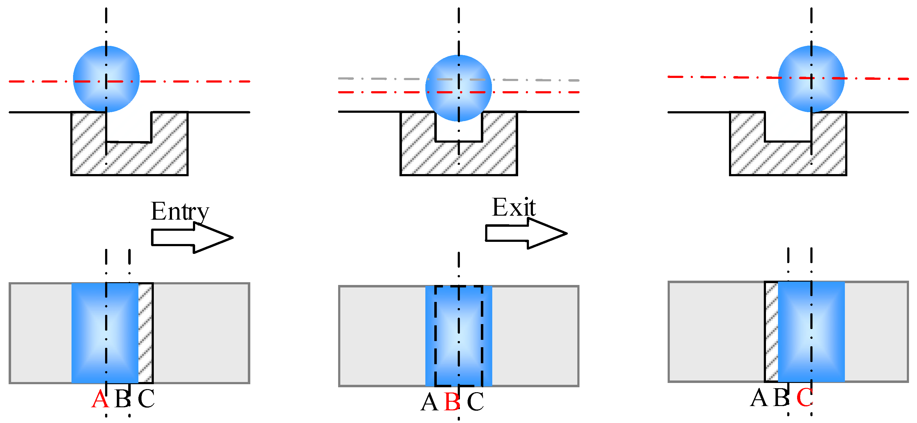
2.1. Vibration Response of Spalled Roller Bearings with Penetrating Damage

The contact form of the ball bearings is the point contact. When a ball bearing rolls over the spalled zone, there are force changes caused by contact deformation at the entry and exit points. Based on the contact force change at different angular positions, the dynamic model of the faulty ball bearings can be established and used to describe the dual-impulse phenomenon. During the working of a roller bearing, the rollers will continuously impact the fault zone in the raceway. The non-penetrating damage may gradually expand into penetrating damage, especially in the situation of excessive load and vibration. The penetrating damage is considered the fault, whose defect length in the axial direction is equal to the raceway width of the roller bearing. When the roller passes over the fault zone, the bearing reaction force will suddenly change, as the clearance changes between the rollers and the raceway. Then, the dual-impulse phenomenon can be found in the vibration signal. The vibration mechanism of the roller bearing with penetrating damage is similar to the ball bearing having a spalled fault. Therefore, when the vibration signal is used to analyze the TRB with penetrating damage, the method of analyzing faulty ball bearings can be used.
To simplify the study, take the roller bearing having a rectangular fault in the outer raceway as an example. In Figure 1, when the roller moves from edge A to center B of the fault zone of the outer raceway or the inner raceway, the roller center has an apparent drop when compared with the roller rolling through the normal raceway. Since the roller falls into the fault area, the internal clearance of the roller bearing will increase [29]. And the first impulse occurs in the vibration signal when the rolling element rolls over the leading edge of the fault. In this process, the forces acting on the roller are the gravitational force and the centrifugal force. When the roller moves from the fault center B to the other fault edge C of the bearing raceway, an impact response occurs in the vibration signal. Contrary to the entry process, the center position of the roller gradually returns to the normal position. When the roller’s center runs to the line connecting the faulty edge C and the roller bearing’s center, the roller returns to the normal state. It can then be concluded that the double impulses responses of the roller over the penetrating damage zone are also composed of the step response related to the entry event and the impact response related to the exit event.

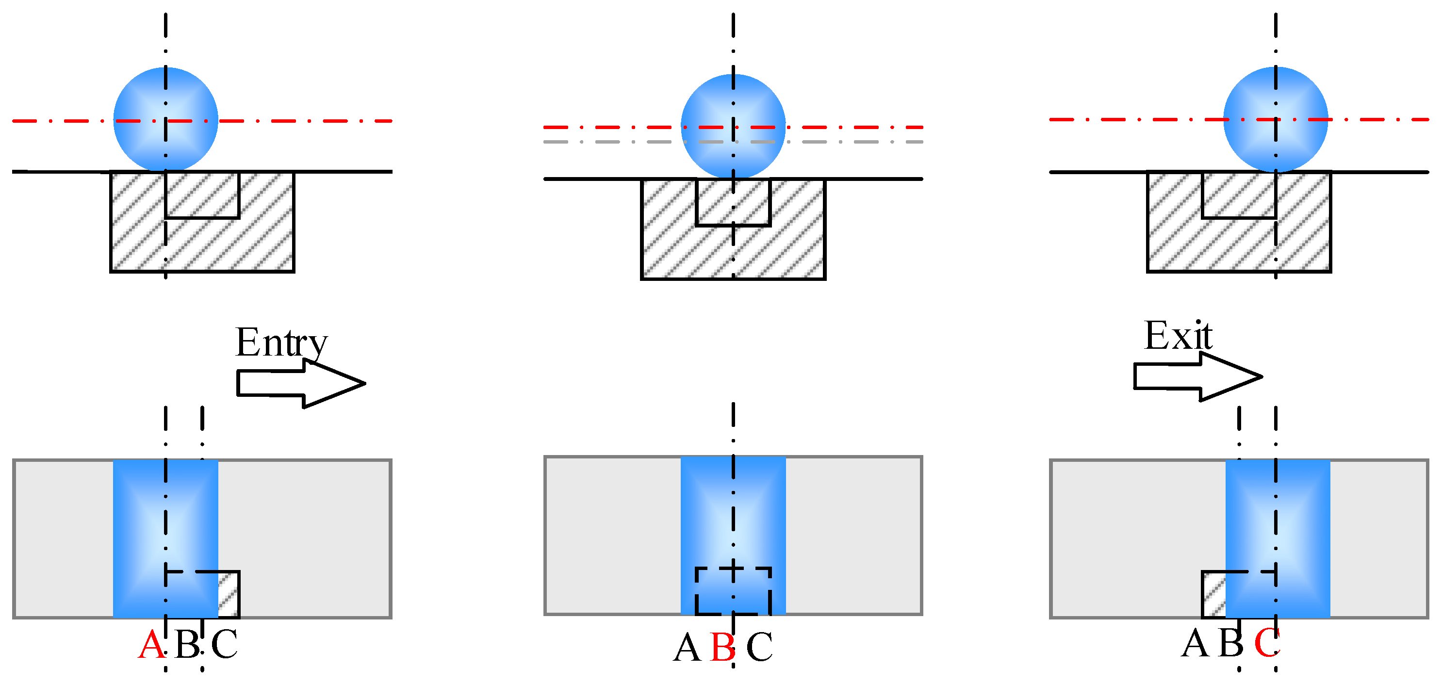
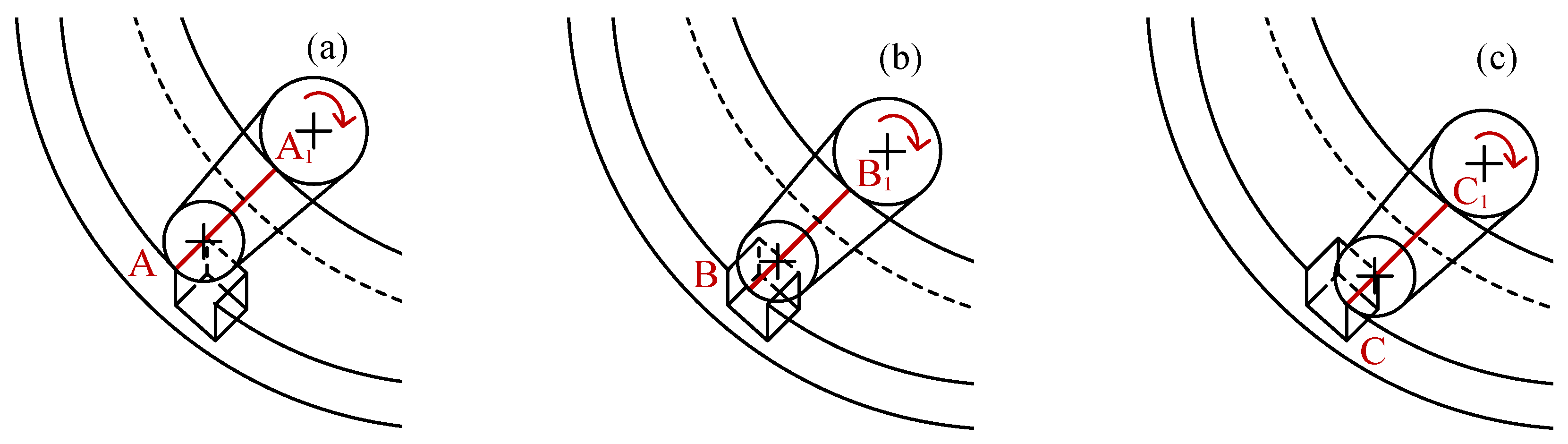
2.2. Vibration Response of Spalled Roller Bearings with Non-Penetrating Damage

This section aims to reveal the vibration mechanism of a roller bearing having non-penetrating damage in the outer raceway or the inner raceway. A dynamic model of the roller bearings considering the influence of non-penetrating damage can be established, based on the contact force change and the contact deformation change. However, the modeling method is different from the method of a roller bearing having penetrating damage. This is because of their different contact state in the fault zone. When the roller passes over the non-penetrating fault zone, the roller always keeps in contact with the raceway. Therefore, there will be no zero contact force as the rolling element enters the fault zone. Furthermore, when the roller rolls to the fault center, the roller will not contact and collides with the defect edge. Hence, the model of the roller bearings with penetrating damage cannot reflect the vibration mechanism of the non-penetrating damage.
To simplify the study, take the roller bearing having a non-penetrating rectangular fault in the outer raceway as an example, and the axial length of the fault zone is less than the width of the raceway. Figure 2 shows the schematic diagram of the dual-impulse behavior caused by the non-penetrating damage. Since the contact state between the roller and the raceways is the line contact, a roller cannot drop the defect zone as it enters from the defect edge A. However, the contact length between the roller and the faulty raceway will become smaller in the defect area, which will change the contact stiffness and the oil film-damping of the fault zone. Hence, the vibration response will be excited by the force change related to the bearing stiffness and damping. The contact length between the roller and the raceway remains unchanged in the process of the roller entering the fault area from fault edge A, passing through fault center B, and reaching fault edge C. After the roller leaves the fault zone and enters the normal raceway, the contact state between the roller and the raceways returns to normal. The second vibration response is excited with the contact force change. The final result is that a series of double impulses will appear in the vibration signal as the rollers continuously enter and leave the fault zone.

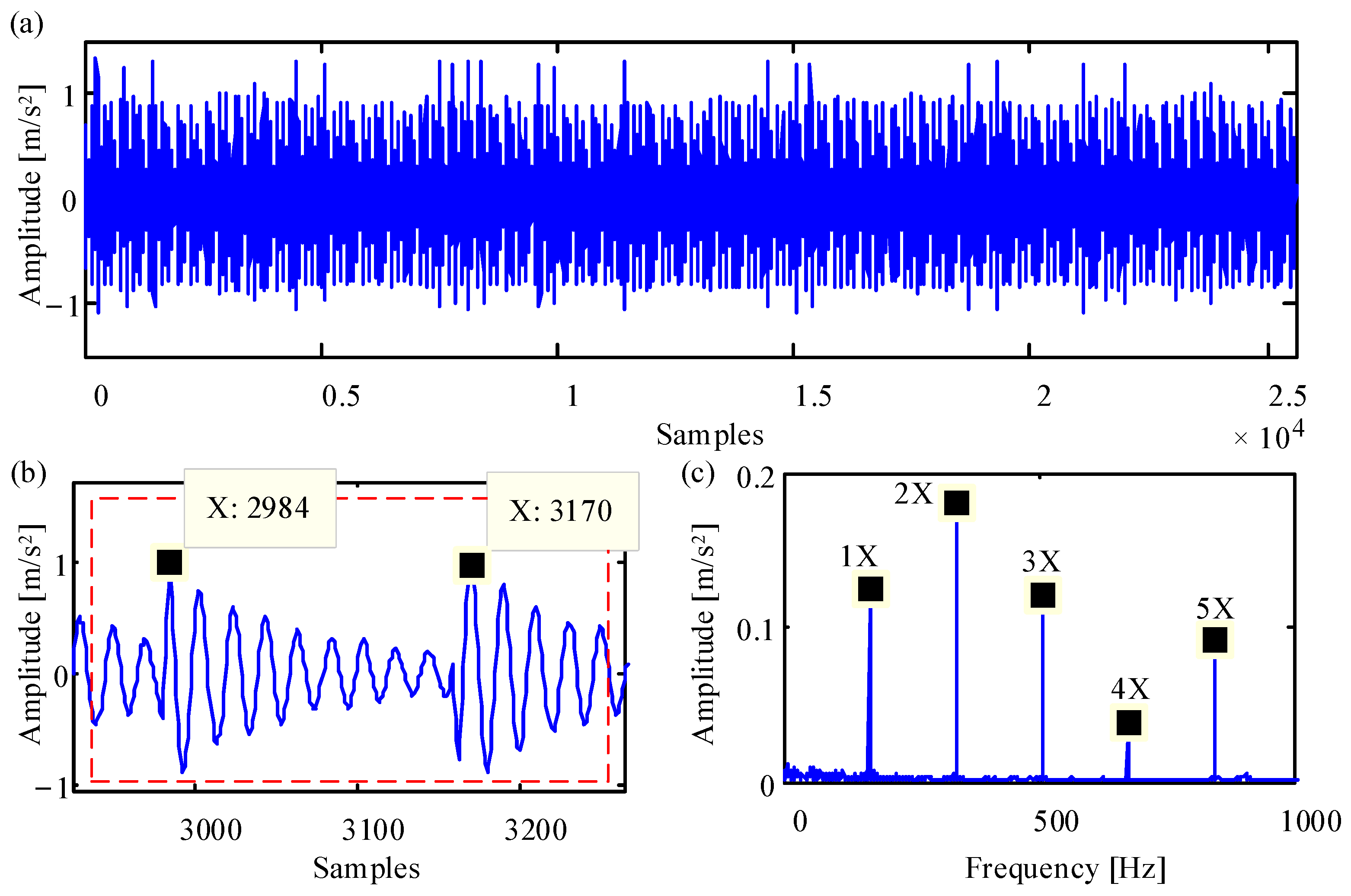
2.3. Fault Size Estimation of Roller Bearings

The time interval of the double impulses in the vibration signal is useful to calculate the fault size along the circumference [6]. When the outer raceway of the roller bearing has a spalled fault, the defect width L (mm) in the circumferential direction has the following relationship with the time t (s) as the rolling element over the defect zone:
t = L π D e f c
where De is the outer raceway diameter of the rolling element bearings; fc is the cage rotation frequency of the rolling element bearings; and
D e = D p + d
f c = 1 2 f r ( 1 d D p cos ( α e ) )
in which Dp denotes the pitch diameter of the rolling element bearings; d is the diameter of the rolling element; fr is the rotation frequency of the shaft; and αo is the contact angle between the rolling element and raceways.
When the contact angle α is zero, the time as the rolling element passing over the defect area can be obtained by introducing Equations (2) and (3) into Equation (1), as follows:
t = 2 L D p π f r ( D p 2 d 2 )
According to the traditional method [6], the impacts’ interval time points tsp produced by the rolling element when entering and leaving the spalled zone corresponds to half of the spalled zone width L, namely:
t = 2 t s p / f s
where fs is the sampling frequency of the measured signal.
Substituting the Formula (5) into the Formula (4) can be obtained:
t s p = L D p f s π f r ( D p 2 d 2 )
Hence, the traditional method [6] uses the dual-impulse time interval of the vibration acceleration signal to calculate the spalled width of the rolling element bearings can be expressed as follows:
L = π f r ( D p 2 d 2 ) D p f s t s p
The traditional method has shown that it can be used to calculate the spalled size of the ball bearings [17]. According to the vibration mechanism of the roller bearings with penetrating damage shown in Figure 1, the Formula (7) can also be used to estimate the penetrating defect size of the roller element bearings. However, it should be noted that the dual-impulse behavior caused by non-penetrating damage in the roller bearing raceways is different from that of the spalled fault in ball bearing raceways. The traditional methods cannot be directly utilized to estimate the circumferential size of non-penetrating.
Figure 2 shows no apparent drop on the entry edge and no impulse on the fault center as the roller rolls over the non-penetrating zone of the faulty roller bearing. The dual-impulse behavior is caused by the change in the comprehensive contact stiffness when a roller ultimately enters the fault zone and completely exits the fault zone. To the roller bearing with a spalled fault in the raceways, the time interval of the dual-impulse feature related to the non-penetrating damage is twice the time interval of the double impulses caused by the penetrating damage. Hence, the Formula (5) is revised as follows:
t = k t s p / f s ( k = 1   o r   2 )
where k represents the damage factor under different fault types, in which its value is 1 for penetrating damage, and its value is 2 for non-penetrating damage.
By introducing Equations (2), (3) and (8) into Equation (1), the relationship between the dual-impulse time interval of the vibration signal and the spalled width of the faulty roller bearing can be expressed as:
t s p = 2 L D p f s k p f r [ ( D p 2 d 2 cos α e ) + D p d ( 1 cos α e ) ]
Then, a revised formula is proposed for estimating the spalled size in the roller bearing raceways:
L = k π f r t s p 2 D p f s [ ( D p 2 d 2 cos α e ) + D p d ( 1 cos α e ) ]

3. Dynamic Modeling for Fault TRB

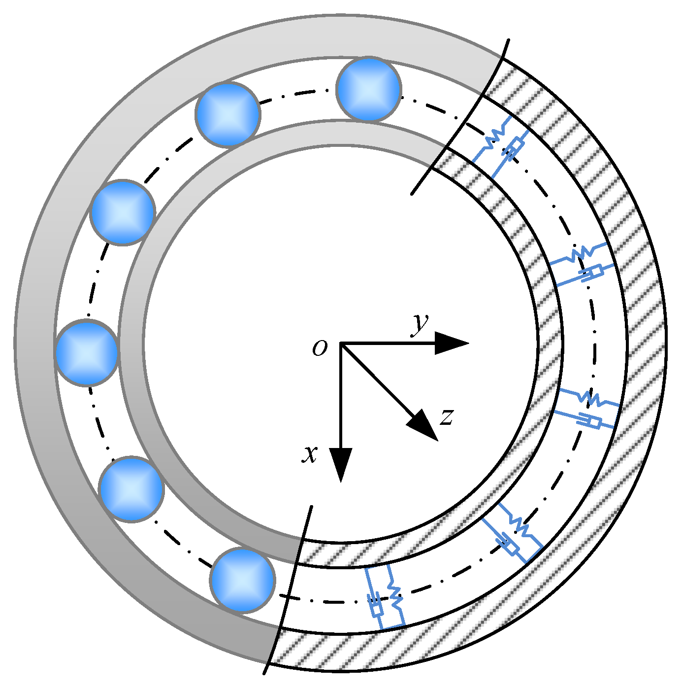
3.1. Dynamic Model of TRB

In order to analyze the dynamic characteristics of the roller bearing and quantify the fault size of the roller bearing, the roller is simplified as a nonlinear contact spring based on the assumption of Patel et al. [30], as shown in Figure 3. According to the theory of the single-degree-of-freedom contact vibration system, the simplified three-degree-of-freedom dynamic model of TRB can be expressed as:
{ m x ¨ + c x x ˙ + k x x = F x m y ¨ + c y y ˙ + k y y = F y m z ¨ + c z z ˙ + k z z = F z
where m is the total mass of the inner raceway and shaft; the symbols c, k, and F represent the internal damping coefficients, the internal stiffness coefficients, and the external load of the roller bearing, respectively. The subscript x, y, and z are used to indicate the different directions of the roller bearings.
The forces related to the internal stiffness of the TRB can be calculated as follows:
{ k x x = j = 1 Z Q j cos α e cos φ j k y y = j = 1 Z Q j cos α e sin φ j k z z = j = 1 Z Q j sin α e
where αe is the contact angle between the roller and the raceway of TRB; φj represents the position angle of the roller. The roller–raceway contact load Qj can be calculated by a roller–raceway contact analysis, to fit the nonlinear contact stiffness expression shown in Equation (13). To more accurately simulate the influences of the elastic approach and contact pressure distribution between the roller and the inner or outer raceways under the non-penetrating damaged state, the roller–raceway contact model [28] is used to simulate the contact state between the roller and the single-sided raceway, based on the non-Hertz contact theory. The roller–raceway contact model analyzed the influence of the roller deflection angle. The detailed calculation can be found in the author’s earlier research literature [28]:
Q j = k d j n
in which k and n are the coefficients related to contact stiffness. The dj represents the relative displacement of the outer ring in the contact normal direction between the roller and the outer raceway. Here, the relative displacement dej between the jth roller and the raceway is expressed as:
d e j = d r j cos α e + d z j sin α e = x i cos φ j cos α e + y i sin φ j cos α e + z i sin α e
where d represents the relative displacement of the outer ring, the subscript r, z, and e, respectively, represent the radial component, the axial component, and the normal contact component between the roller and the raceway.

3.2. Equivalent Oil Film Damping between Roller and Raceway

The lubricating oil film damping between the roller and the raceway is significant to calculate the forces (cx x ˙ , cy y ˙ , cz z ˙ ), related to the internal resistance of TRB. In the case of ignoring oil leakage at the roller end, the Reynolds’ equation of the lubricant film between the roller and the raceway can be simplified as [31,32]:
x ( h 3 12 η 0 p x ) = 1 2 ( h u ) x + v z
where η0 is the lubricant viscosity in the atmospheric environment; h and p, respectively, represent the oil film thickness and the oil film pressure of the roller–raceway contact pair; u is the entrainment speed between the roller and the raceway; and vz is the normal extrusion speed of the roller–raceway contact pair.
According to the Sommerfeld condition and the semi-Sommerfeld condition, Equation (13) can be integrated as:
Q = 4 η 0 u R l h c + 6 π η 0 v z R 1.5 l 2 h c 1.5
in which Q is the bearing capacity of oil film between the roller and the raceway; l and R, respectively, represent the effective length and the equivalent contact radius of the roller–raceway contact pair. The film thickness in the center of the roller–raceway contact pair is expressed by hc, for which the calculation process is as follows:
h c = 11.9 α 0 0.4 ( η 0 u ) 0.74 R 0.46 E 0.14 w 0.2
where α0 is the pressure viscosity coefficient; and E is the comprehensive elastic modulus between the roller and the raceway. The contact load coefficient w between the roller and the raceway can be calculated as:
w = Q / l
The second term at the right end of the Formula (16) describes the film pressure related to the extrusion speed, which is the source of the lubricant film damping. So, the film damping between the roller and raceway can be approximately expressed as linear damping:
c e , i = Q v z = 6 π η 0 R 1.5 l 2 h c 1.5
Since there is a lubricant film between the roller and the inner and outer raceways, the equivalent lubricant film damping at each roller is the series connection of the lubricant film damping between the roller and the inner and outer raceways:
c = c e c i cos ( α e α i ) c e + c i cos ( α e α i )
When the difference in the contact angle between the roller and the inner and outer raceways is small, the Formula (20) can simplify as:
c = c e c i c e + c i
In which ce and αe, respectively, represent the film damping and contact angles between the roller and the outer raceways; ci and αi, respectively, represent the film damping and contact angles between the roller and the inner raceways.
Hence, the internal damping forces can be expressed as the Formula (22) in solving the TRB’s dynamic model:
{ c x x ˙ = j = 1 Z F c j cos α e cos φ j c y y ˙ = j = 1 Z F c j cos α e sin φ j c z z ˙ = j = 1 Z F c j sin α e
where Fcj is the damping force of the lubricant film at the jth roller, which is a function of the ring vibration speed and the oil film damping between the roller and the inner and outer raceways:
F c = c e c i c e + c i ( x ˙ cos α e cos φ j + y ˙ cos α e sin φ j + z ˙ sin α e )

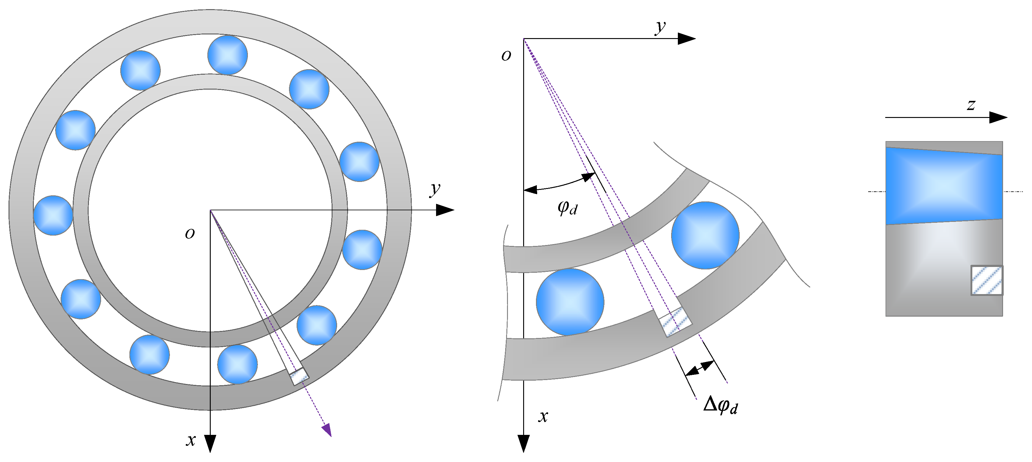
3.3. Dynamic Modeling for Non-Penetrating Damage in the Outer Raceway of TRB

According to the vibration response caused by the non-penetrating damage in the outer raceway, the contact length will change as the roller enters the fault zone from the normal raceway and leaves the fault zone to the normal raceway. This change will cause both the contact stiffness and oil film damping to change. When entering and leaving the edge of the damage, a variable, comprehensive contact-stiffness vibration occurs between the rings. Based on this, the quasi-dynamic model of a TRB with non-penetrating damage in the outer raceway can be established.
The damage location is a crucial parameter for the dynamic modeling of the faulty TRB. Figure 4 takes the non-penetrating rectangular fault of the TRB as an example to describe the damage’s position as follows: the damage location angle φd and the damage angle width Δψd are defined to characterize the fault area, where the arc length corresponding to the damage angle width is the damage width. Among them, the damage position angle φd describes the circumferential position of the damage center, and the damage angle width Δψd is used to describe the circumferential radian range of the non-penetrating damage in the raceway. When the TRB is working, the angular position of a tapered roller will change with time. For determining the contact state between the jth roller and the raceway, the Formula (24) is constructed by the relationship between the roller position angle and the damage position angle:
| φ j 0 + ω c t φ d | < Δ ψ d 2
where φj0 is the initial angular position of the jth roller; ωc is the angular velocity of the roller revolving around the bearing axis; and t represents the bearing rotation time.
When a tapered roller passes over the outer raceway, the contact width between the roller and the raceway is small. Note that the processes of a tapered roller’s entry into or exit from the spalled zone are also much less than the process of the tapered roller completely over the defect area. So, the gradual process of the elastic approach can be ignored in analyzing the dynamic and static problems of the faulty roller bearing dominated by the elastic approach between the roller and the raceway. For details, please refer to the literature [27] on the change analysis of the dimensionless elastic approach between the roller and raceway in the processing of the roller passing over the defect. Figure 5 shows the process of a tapered roller entering the fault zone, rolling over the fault center, and then leaving the fault zone. In establishing the quasi-dynamic model of TRB with the non-penetrating defect in the outer raceway, the contact model of the roller over the fault zone applies a rectangular wave function to approximately reflect the change in the elastic displacement. The force related to the stiffness change is calculated according to Formulas (12) and (13).
In addition, lubrication factors are also introduced into the quasi-dynamic model of a TRB having a non-penetrating spall in the outer raceway. According to the calculation formula of the center oil film thickness shown in Equation (17), the load factor has little effect on the center oil film thickness. Therefore, when calculating the damping coefficient between the roller and the raceway, the proposed model only considers the influence of the fault width ld on the contact length l between the roller and the raceway. The damping coefficient of a tapered roller at different positions can be shown in Equation (25). By bringing it into Equation (22), the damping force can be obtained:
c = { 6 π η 0 R 1.5 l 2 ( 11.9 α 0 0.4 ( η 0 u ) 0.74 R 0.46 E 0.14 ( Q / l ) 0.2 ) 1.5 | φ j 0 + ω c t φ d | Δ ψ d 2 6 π η 0 R 1.5 ( l l d ) 2 ( 11.9 α 0 0.4 ( η 0 u ) 0.74 R 0.46 E 0.14 ( Q / ( l l d ) ) 0.2 ) 1.5 | φ j 0 + ω c t φ d | < Δ ψ d 2
Based on the above analysis, the differential equation for a TRB with the non-penetrating damage is constructed as follows:
{ m x ¨ + j = 1 Z F c j cos α e cos φ j + j = 1 Z Q j cos α e cos φ j = F x m y ¨ + j = 1 Z F c j cos α e sin φ j + j = 1 Z Q j cos α e sin φ j = F y m z ¨ + j = 1 Z F c j sin α e + j = 1 Z Q j sin α e = F z

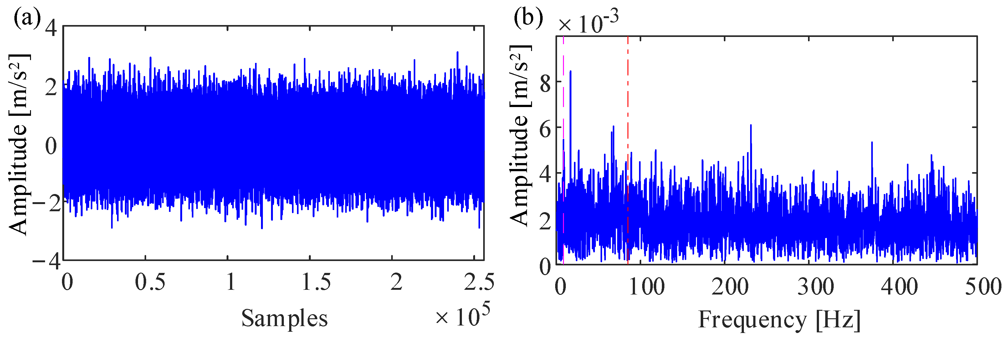
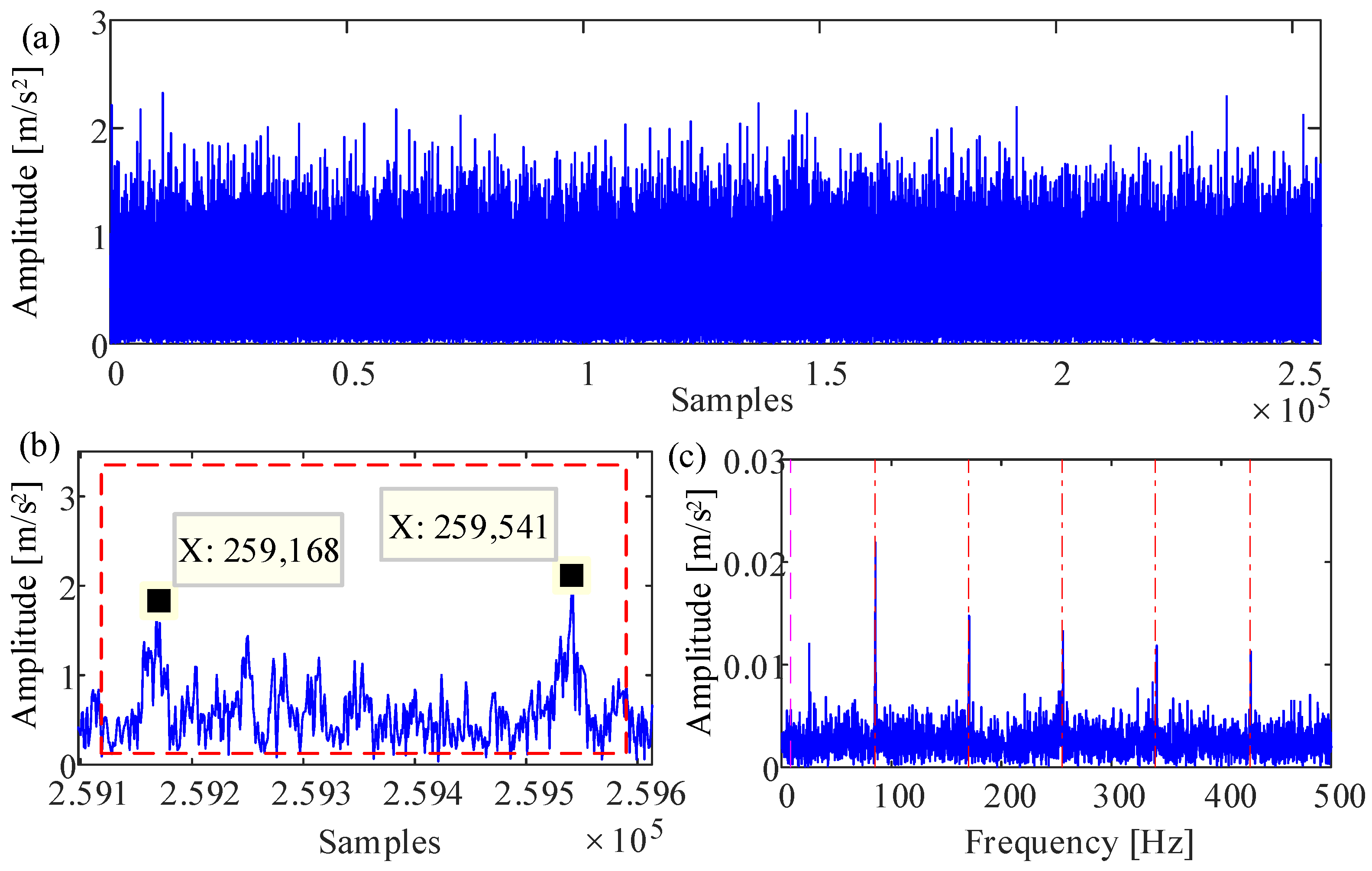
4. Simulation Analysis

This paper chooses the 32008 TRB as the research object to perform the simulation. Table 1 presents the geometric parameters of the 32008 TRB. The total mass of the inner ring and the shaft is 5 kg, the lubricant viscosity in the atmospheric environment is 1.9 × 10⁻² Pa·s, the pressure viscosity coefficient of the lubricant is 2.0 × 10⁻⁸ m2/N, the comprehensive elastic modulus between the roller and the raceway is 1.1379 × 10⁵ N/mm2. The material of the TRB is steel. During the modeling process, the time step Δt is set to 5.12 × 10⁻⁶ s, and the axial load applied to the shaft is 340 N. The non-penetrating damage in the outer raceway of the TRB is simulated using a rectangular edge fault, in which the axial fault length is 4 mm, and the circumferential length is 5 mm. The Runge–Kutta algorithm is used to solve the established model for obtaining the vibration signal.
According to the dynamic model of a TRB with non-penetrating damage in the outer raceway, the vibration response at different working speeds was simulated. Figure 6a presents the vibration acceleration signal of the TRB at 500 rpm. Since there is no interference from background noise, the impulses caused by the defect are clear. Figure 6b shows one local signal of the raw vibration signal, in which the dual-impulse phenomenon is obvious. The time interval of the double impulses is 365 sampling points. Envelope analysis is utilized to extract the fault characteristic for verifying the correctness of the established model. The envelope spectrum of the raw vibration signal is shown in Figure 7c. Obviously, the characteristic frequency and its multiplier of the defect are visible. So, the established model can be used to reflect the non-penetrating damage in the outer raceway of the TRB. When the rotor speed is 1000 rpm, the raw vibration signal generated by the established model is presented in Figure 7a, and one local signal is shown in Figure 7b. Though the speed has changed, the dual-impulse phenomenon is evident. The time interval of 180 sampling points can be obtained from the local signal. Figure 7c shows the envelope spectrum of the raw vibration signal. In the figure, the fault frequency is easily observed.
The simulation analysis gives the vibration response of TRB with non-penetrating damage in the outer raceway. Moreover, the proposed method is applied based on the double impulses in the simulated signal for quantifying the fault size. Table 2 is the comparison results between the theoretical and simulated time of the double impulses. Within the error tolerance, all of the estimated fault size is consistent with the theoretical size. The proposed method proves to be useful for quantifying the defect. So, the estimated model can be used to research the vibration mechanism of the non-penetrating defect.

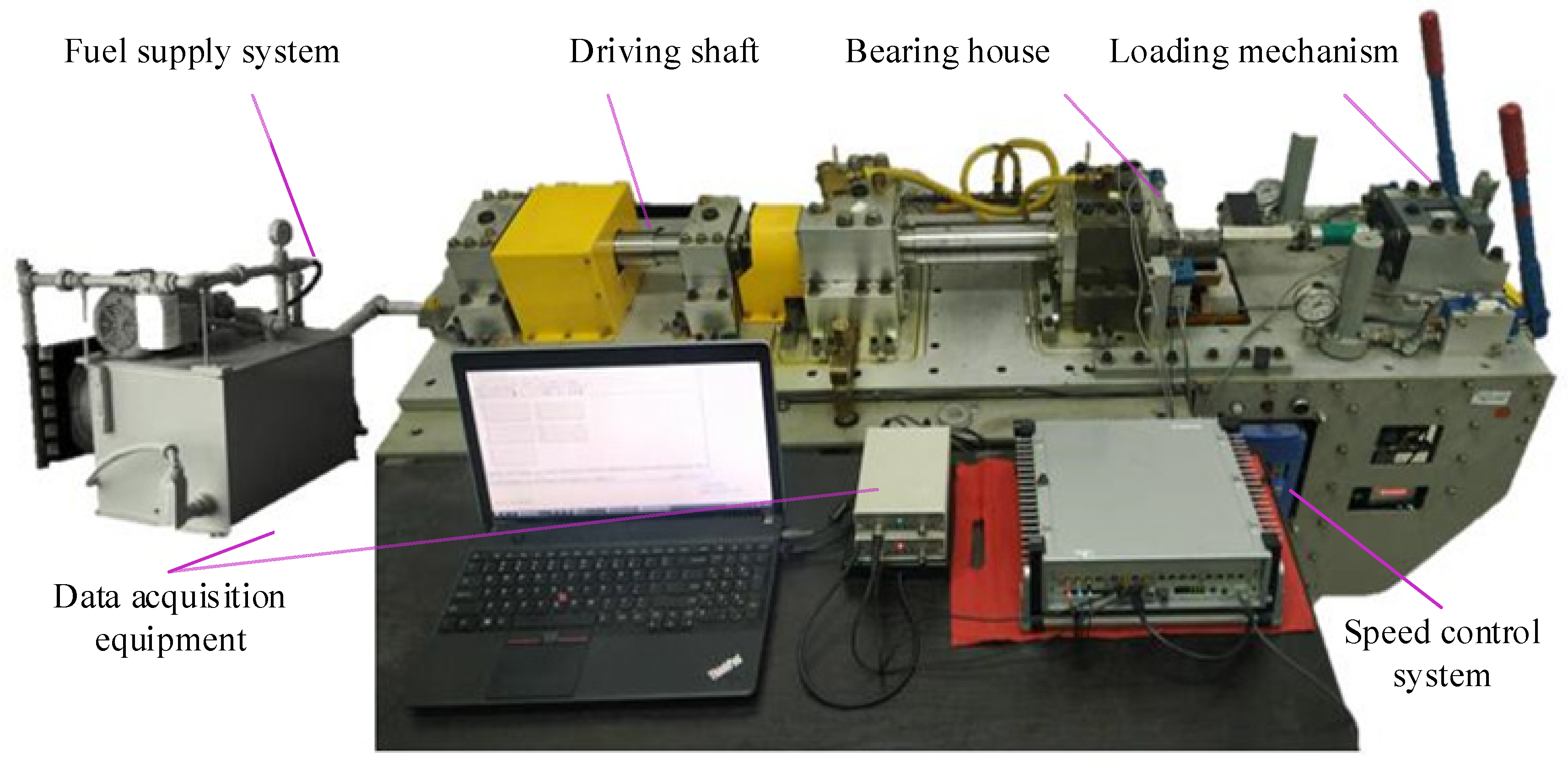
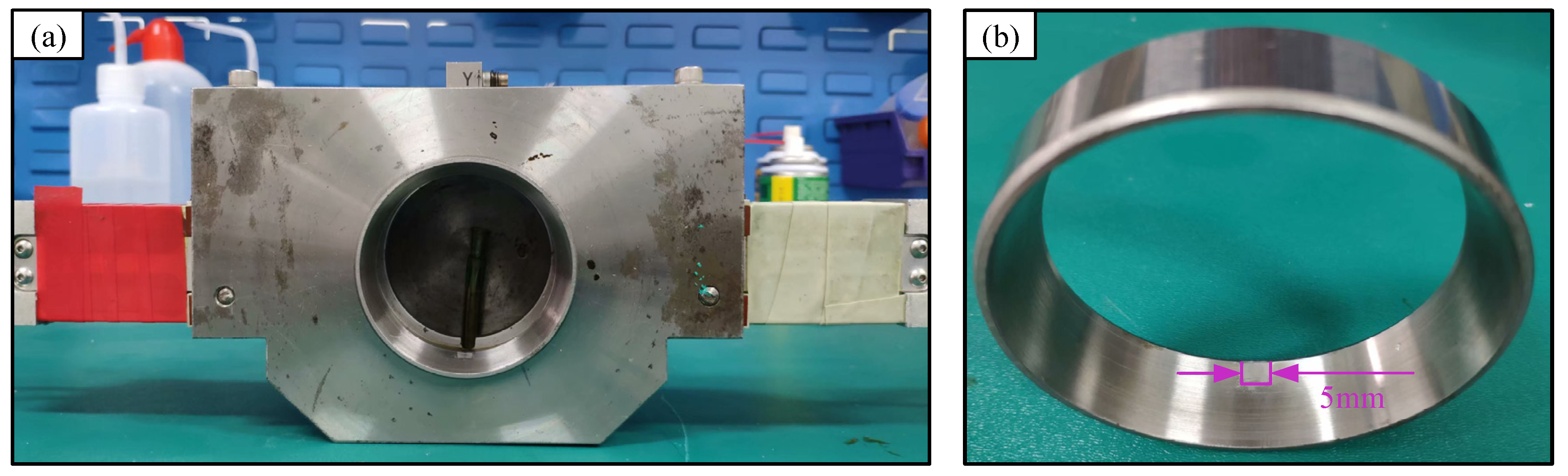
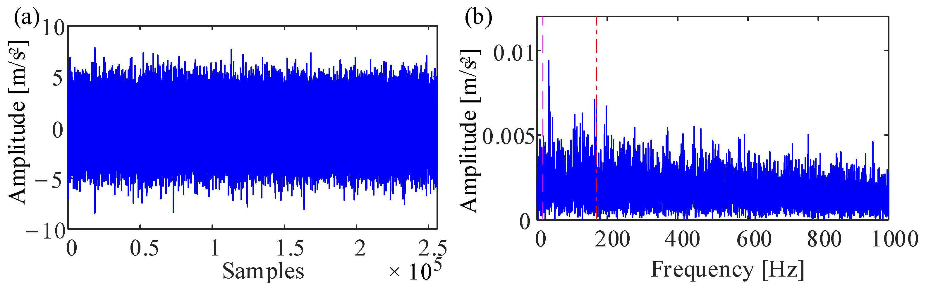
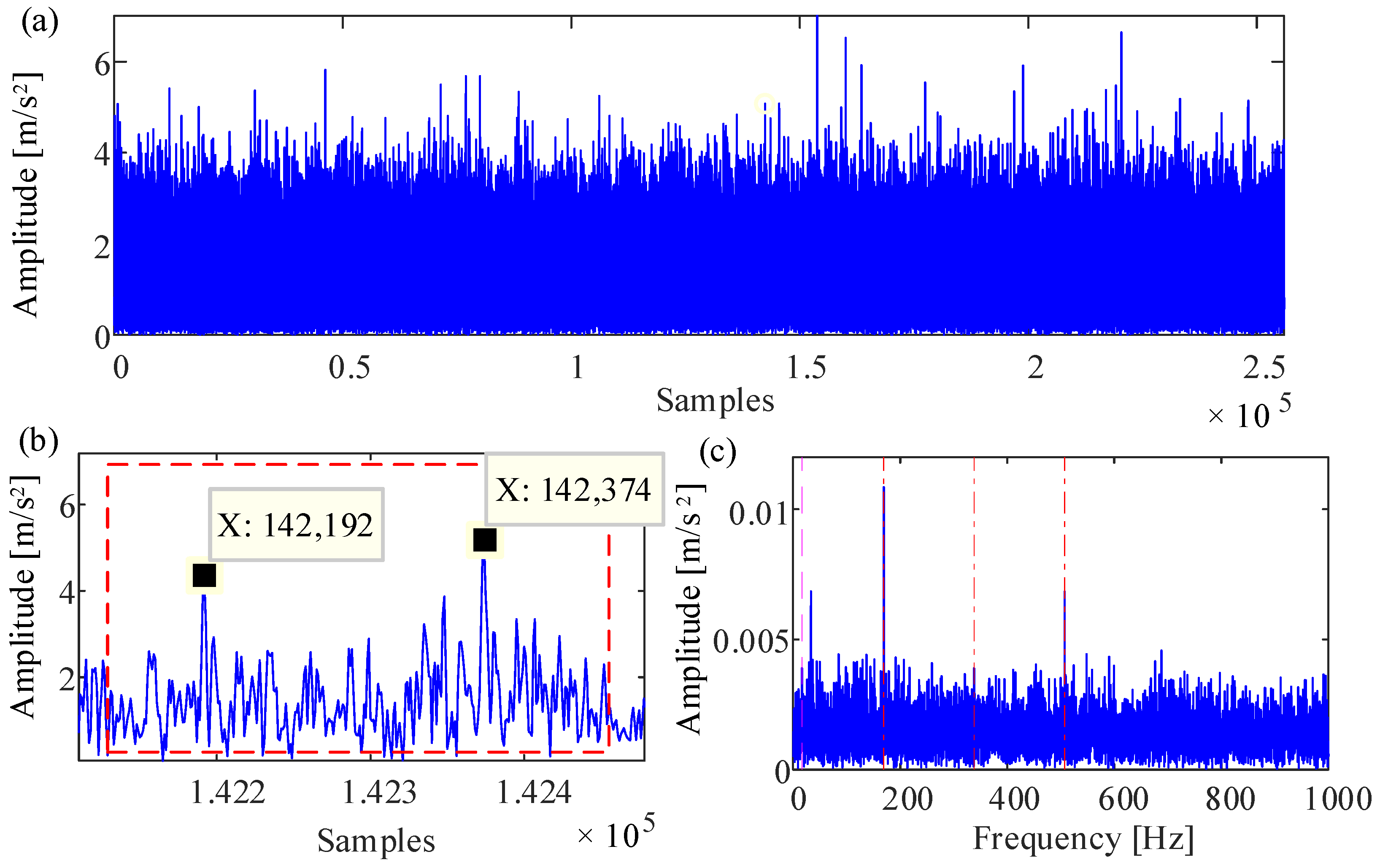
5. Experimental Analysis

The Bearing Prognostics Simulator (BPS), produced by SpectraQuest, is used to perform the test, as shown in Figure 8. A three-phase AC motor provides the power for the BPS, in which the motor drives the driving shaft via a V-belt. Moreover, the speed control system is applied to adjust the shaft speed for meeting the needs of the various working conditions. The loading mechanism provides the axial force and the radial force via two hydraulic cylinders. The fuel supply system is used to supply the lubricating oil for the rig. The vibration acceleration signal is collected by a three-axis accelerometer installed on the top of a bearing house, as shown in Figure 9a. The data acquisition equipment consists of a computer and a PAK Mobile MK II. All of the vibration signals are acquired with a sampling frequency of 51.2 kHz. Figure 9b shows the outer ring of a test TRB, which has a rectangular defect in the edge. A non-penetrating defect was machined at the small end of the outer raceway by the electrochemical corrosion method, and its axial length, depth, and circumferential length are, respectively, 4 mm, 0.03 mm, and 5 mm.
Figure 10a presents the original signal collected from the bearing seat when the speed is 500 rpm. Since the non-penetrating damage is weak, the dual-impulse extraction is not easy to obtain from the raw vibration signal. Envelope analysis is an effective method to diagnose the fault in the rolling element bearing. The envelope spectrum of the measured signal is shown in Figure 10b, in which the fault characteristic frequency is submerged in noise frequency components. To extract the double impulses, this paper enhanced the fault characteristic with both Autoregressive (AR) and Minimum Entropy Deconvolution (MED). The AR is utilized to weaken the periodic interference, and the MED method is applied to enhance the impulse feature. In the literature [6], the above methods have shown effectiveness in observing the double impulses. Figure 11a is the resulting filtered envelope signal, and a local signal of the filtered signal is shown in Figure 11b. One dual-impulse feature can be observed from the local signal, and its time interval is 373 sampling points. Figure 11c presents the envelope spectrum of the signal processed by both AR and MED, in which the fault frequency is obvious compared with the envelope spectrum of the raw signal. The fault signal has been enhanced, and the processed signal can be used to analyze the dual-impulse phenomenon.
In addition, the vibration acceleration signal at 1000 rpm is collected from the bearing seat. Figure 12a,b shows the original signal and its envelope spectrum, respectively. As the rotor speed increases, a peak occurs in the fault frequency position, but it is not the most obvious frequency. The fault signal is disturbed by background noise and cannot analyze the double impulses directly. The method based on AR and MED [6] is also applied to filter the original vibration signal, and the envelope of the filtered signal is presented in Figure 13a. Figure 13b presents one local signal, in which the dual-impulse time interval is 182 sampling points. The envelope spectrum of the processed signal is shown in Figure 13c. The fault frequency and its multipliers are effectively extracted, so the signal shown in Figure 13a is useful to analyze the dual-impulse characteristic.
The Formula (10) is applied to calculate the defect length in the circumferential direction based on the double impulses in a vibration signal. The error analysis and comparison verification with the theoretical fault size are carried out, and the results are summarized as presented in Table 3. Though the dual-impulse time interval of the test signal is not the same as the dual-impulse time interval calculated from the estimated model, the error at different speeds is less than 3.74%. Moreover, the defect size estimated by the proposed method is close to the theoretical fault size. The established model proves to be effective, and the new estimation method is useful for quantifying the non-penetrating damage in the outer raceway of the TRB.

6. Conclusions

This paper analyzes the vibration responses of the roller bearings with penetrating damage or non-penetrating damage. According to the double impulses in the vibration signal, a method is proposed for estimating the fault size of non-penetrating damage in the outer raceway of the TRB. This measurement method uses the dual-impulse interval to calculate the circumferential length of the fault zone, which provides a reliable guide for the TRB’s residual life evaluation and prediction.
A dynamic model is constructed to reveal the vibration mechanism of the non-penetrating damage in the TRB’s outer raceway. The proposed model introduces a roller–raceway contact model to calculate the force related to the stiffness changes as the roller enters, passes, and leaves the non-penetrating zone. In addition, the damping force related to the change in the lubricating oil film thickness is also used for modeling.
The simulation and experimental analysis verify the correctness of the proposed method and the established model. The circumferential length of a defect zone can be effectively estimated based on the dual-impulse interval extracted from the vibration acceleration signal. This research lays a theoretical foundation for the accurate condition monitoring and residual life analysis of smart TRBs.

Author Contributions

Conceptualization, W.K.; methodology, W.K. and Y.L.; validation, Y.Z., K.Y. and W.K.; formal analysis, W.K. and Y.L.; investigation, D.G. and Z.R.; resources, K.Y.; data curation, W.K. and Y.L.; writing—original draft preparation, W.K.; writing—review and editing, Y.Z., K.Y. and W.K.; supervision, Y.Z.; project administration, Y.Z.; funding acquisition, Y.Z. All authors have read and agreed to the published version of the manuscript.

Funding

This research was funded by the National Key R&D Program of China (Grant nos. 2019YFB2004302).

Data Availability Statement

Detailed data are contained within the article.

Conflicts of Interest

The authors declare no conflict of interest.

References

  1. Yan, K.; Dong, L.; Zheng, J.; Li, B.; Wang, D.; Sun, Y. Flow performance analysis of different air supply methods for high speed and low friction ball bearing. Tribol. Int. 2018, 121, 94–107. [Google Scholar] [CrossRef]
  2. Van Horenbeek, A.; Van Ostaeyen, J.; Duflou, J.R.; Pintelon, L. Quantifying the added value of an imperfectly performing condition monitoring system—Application to a wind turbine gearbox. Reliab. Eng. Syst. Saf. 2013, 111, 45–57. [Google Scholar] [CrossRef]
  3. Kang, W.; Zhu, Y.; Yan, K.; Ren, Z.; Gao, D.; Hong, J. Research on extracting weak repetitive transients of fault rolling element bearing. ISA Trans. 2021, 123, 381–397. [Google Scholar] [CrossRef]
  4. Zhang, Y.; Li, Y.; Kong, L.; Niu, Q.; Bai, Y. Improved DBSCAN Spindle Bearing Condition Monitoring Method Based on Kurtosis and Sample Entropy. Machines 2022, 10, 363. [Google Scholar] [CrossRef]
  5. Zhang, F.; Huang, J.; Chu, F.; Cui, L. Mechanism and Method for Outer Raceway Defect Localization of Ball Bearings. IEEE Access 2020, 8, 4351–4360. [Google Scholar] [CrossRef]
  6. Sawalhi, N.; Randall, R.B. Vibration response of spalled rolling element bearings: Observations, simulations and signal processing techniques to track the spall size. Mech. Syst. Signal Process. 2011, 25, 846–870. [Google Scholar] [CrossRef]
  7. Epps, I.K. An Investigation into Vibrations Excited by Discrete Faults in Rolling Element Bearings: School of Mechanical Engineering. Ph.D. Thesis, The University of Canterbury, Christchurch, New Zealand, 1991. [Google Scholar]
  8. Sharma, R.B.; Parey, A. Modelling of acoustic emission generated in rolling element bearing. Appl. Acoust. 2017, 144, 96–112. [Google Scholar] [CrossRef]
  9. Al-Ghamd, A.M.; Mba, D. A comparative experimental study on the use of acoustic emission and vibrationanalysis for bearing defect identification and estimation of defect size. Mech. Syst. Signal Process. 2006, 20, 1537–1571. [Google Scholar] [CrossRef] [Green Version]
  10. Ming, A.; Zhang, W.; Qin, Z.; Chu, F. Dual-Impulse Response Model for the Acoustic Emission Produced by a Spall and the Size Evaluation in Rolling Element Bearings. IEEE Trans. Ind. Electron. 2015, 62, 6606–6615. [Google Scholar] [CrossRef]
  11. Tarawneh, C.; Lima, J.D.; Santos, N.D.L.; Jones, R. Prognostics Models for Railroad Tapered Roller Bearings with Spall Defects on Inner or Outer rings. Tribol. Trans. 2019, 62, 897–906. [Google Scholar] [CrossRef]
  12. Montalvo, J.; Tarawneh, C.; Lima, J.; Cuanang, J.; Santos, N. Estimating the Outer Ring Defect Size and Remaining Service Life of Freight Railcar Bearings using Vibration Signatures. In Proceedings of the ASME/IEEE Joint Rail Conference, Snowbird, UT, USA, 9–12 April 2019. [Google Scholar]
  13. Lima, J.; Tarawneh, C.; Aguilera, J.; Cuanang, J. Estimating the Inner Ring Defect Size and Residual Service Life of Freight Railcar Bearings using Vibration Signatures. In Proceedings of the ASME/IEEE Joint Rail Conference, St. Louis, MO, USA, 20–22 April 2020. [Google Scholar]
  14. Zhao, M.; Lin, J.; Miao, Y.; Xu, X. Detection and Recovery of Fault Impulses Via Improved Harmonic Product Spectrum and Its Application in Defect Size Estimation of Train Bearings. Measurement 2016, 91, 421–439. [Google Scholar] [CrossRef]
  15. Jena, D.P.; Panigrah, S.N. Precise Measurement of Defect Width in Tapered Roller Bearing using Vibration Signal. Measurement 2014, 55, 39–50. [Google Scholar] [CrossRef]
  16. Guo, Y.; Sun, S.B.; Wu, X.; Na, J.; Fung, R.F. Experimental Investigation on Double-impulse Phenomenon of Hybrid Ceramic Ball Bearing with Outer Race Spall. Mech. Syst. Signal Process. 2018, 113, 189–198. [Google Scholar] [CrossRef]
  17. Sawalhi, N.; Wang, W.; Becker, A. Vibration Signal Processing for Spall Size Estimation in Rolling Element Bearings using Autoregressive Inverse Filtration Combined with Bearing Signal Synchronous Averaging. Adv. Mech. Eng. 2017, 9, 168781401770300. [Google Scholar] [CrossRef] [Green Version]
  18. Khanam, S.; Dutt, J.K.; Tandon, N. Impact Force Based Model for Bearing Local Fault Identification. J. Vib. Acoust. 2015, 137, 051002. [Google Scholar] [CrossRef]
  19. Liu, J.; Shao, Y.; Zhu, W. A New Model for the Relationship Between Vibration Characteristics Caused by the Time-Varying Contact Stiffness of a Deep Groove Ball Bearing and Defect Sizes. J. Tribol. Trans. Asme 2015, 137, 031101. [Google Scholar] [CrossRef]
  20. Moazen-Ahmadi, A.; Petersen, D.; Howard, C. A nonlinear dynamic vibration model of defective bearings—The importance of modelling the finite size of rolling elements. Mech. Syst. Signal Process. 2015, 52, 309–326. [Google Scholar] [CrossRef]
  21. Cui, L.; Huang, J.; Zhang, F. Quantitative and Localization Diagnosis of a Defective Ball Bearing Based on Vertical–Horizontal Synchronization Signal Analysis. IEEE Trans. Ind. Electron. 2017, 64, 8695–8706. [Google Scholar] [CrossRef]
  22. Cui, L.; Wang, X.; Wang, H.; Wu, N. Improved Fault Size Estimation Method for Rolling Element Bearings Based on Concatenation Dictionary. IEEE Access 2019, 7, 22710–22718. [Google Scholar] [CrossRef]
  23. Luo, M.; Guo, Y.; Wu, X.; Na, J. An analytical model for estimating spalled zone size of rolling element bearing based on dual-impulse time separation. J. Sound Vib. 2019, 453, 87–102. [Google Scholar] [CrossRef]
  24. Brecher, C.; Fey, M.; Bartelt, A.; Hassis, A. Design and Test Rig Experiments of a High Speed Tapered Roller Bearing for Main Spindle Applications. Procedia CIRP 2016, 46, 533–536. [Google Scholar] [CrossRef] [Green Version]
  25. Liu, Y.; Kang, W.; Zhu, Y.; Yan, K.; Hong, J. Effects of Defect on Roller-Raceway Contact State and Friction Torque of Tapered Roller Bearings. J. Tribol. T ASME 2020, 142, 1–8. [Google Scholar] [CrossRef]
  26. Tsuha, N.; Cavalca, K. Stiffness and damping of elastohydrodynamic line contact applied to cylindrical roller bearing dynamic model. J. Sound Vib. 2020, 481, 115444. [Google Scholar] [CrossRef]
  27. Deng, S.; Gu, J.; Cui, Y.; Zhang, W. Dynamic Analysis of a Tapered Roller Bearing. Ind. Lubr. Tribol. 2018, 70, 191–200. [Google Scholar] [CrossRef]
  28. Liu, Y.; Zhu, Y.; Yan, K.; Wang, F.; Hong, J. A Novel Method to Model Effects of Natural Defect on Roller Bearing. Tribol. Int. 2018, 122, 169–178. [Google Scholar] [CrossRef]
  29. Moazen-Ahmadi, A.; Howard, C.Q. A Defect Size Estimation Method based on Operational Speed and Path of Rolling Elements in Defective Bearings. J. Sound Vib. 2016, 385, 138–148. [Google Scholar] [CrossRef]
  30. Patel, V.N.; Tandon, N.; Pandey, R.K. A Dynamic Model for Vibration Studies of Deep Groove Ball Bearings Considering Single and Multiple Defects in Races. J. Tribol. 2010, 132, 041101. [Google Scholar] [CrossRef]
  31. Dowson, D.; Higginson, G.R.; Nielsen, K.W. Elasto-Hydrodynamic Lubrication (International Series in Material, Science and Technology, Vol. 23). J. Lubr. Technol. 1978, 100, 447. [Google Scholar] [CrossRef]
  32. Zhang, J.; Liu, Y.; Yan, K.; Fang, B. A Fractal Model for Predicting Thermal Contact Conductance considering Elasto-plastic Deformation and Base Thermal Resistances. J. Mech. Sci. Technol. 2019, 33, 475–484. [Google Scholar] [CrossRef]
Figure 1. Schematic diagram of dual-impulse behavior caused by penetrating damage.
Machines 10 00516 g001
Figure 2. Schematic diagram of dual-impulse behavior caused by non-penetrating damage.
Machines 10 00516 g002
Figure 3. Schematic diagram of the spring-damping model.
Machines 10 00516 g003
Figure 4. Schematic diagram of TRB with non-penetrating damage.
Machines 10 00516 g004
Figure 5. Schematic diagram of a tapered roller rolling over the different fault positions: (a) the entry edge; (b) the fault center; (c) the exit edge.
Machines 10 00516 g005
Figure 6. The results of simulated analysis at 500 rpm: (a) raw signal; (b) the local signal of (a); (c) envelope spectrum.
Machines 10 00516 g006
Figure 7. The results of simulated analysis at 1000 rpm: (a) raw signal; (b) the local signal of (a); (c) envelope spectrum.
Machines 10 00516 g007
Figure 8. Bearing prognostics simulator.
Machines 10 00516 g008
Figure 9. (a) Bearing seat; (b) TRB outer ring with fault size 5 mm.
Machines 10 00516 g009
Figure 10. Test results at 500 rpm: (a) raw signal; (b) envelope spectrum, dash-dotted line with red: the fault frequency; dotted line with purple: the rotor frequency.
Machines 10 00516 g010
Figure 11. The results of experimental analysis at 500 rpm: (a) envelope signal filtered by AR and MED; (b) the local signal of (a); (c) the envelope spectrum of (a).
Machines 10 00516 g011
Figure 12. Test results at 1000 rpm: (a) raw signal; (b) envelope spectrum.
Machines 10 00516 g012
Figure 13. The results of experimental analysis at 1000 rpm: (a) envelope signal filtered by AR and MED; (b) the local signal of (a); (c) the envelope spectrum of (a).
Machines 10 00516 g013
Table 1. Structure and material parameters of 32008 TRB.
ParameterValue
Roller-outer raceway contact angle (rad)0.2473
Roller-inner raceway contact angle (rad)0.1949
Small end diameter of tapered roller (mm)6.131
Large end diameter of tapered roller (mm)6.846
Number of tapered rollers23
Half roller angle (rad)0.0262
Pitch diameter (mm)55.1707
Roller length (mm)13.66
Flange angle (rad)1.5621
Table 2. Comparisons between the theoretical and simulated time of the double impulses.
Time and Relative Error Speed (r/min)
5001000
Theoretical time (samples)359.54179.77
Theoretical fault size (mm)5.005.00
Simulated time (samples)373186
Simulated fault size (mm)5.25.2
Relative error (%)3.743.74
Table 3. Comparisons between the theoretical and measured time of the double impulses.
Time and Relative Error Speed (r/min)
5001000
Theoretical time (samples)359.54179.77
Theoretical fault size (mm)5.005.00
Simulated time (samples)373182
Simulated fault size (mm)5.25.1
Relative error (%)3.741.24
Publisher’s Note: MDPI stays neutral with regard to jurisdictional claims in published maps and institutional affiliations.

