
Design Optimization of Deep-Sea Lift Pump Based on Reflux Characteristics


1
College of Mechanical and Electrical Engineering, Changsha University, Changsha 410114, China
2
College of Mechanical and Electrical Engineering, Central South University, Changsha 410083, China
*
Author to whom correspondence should be addressed.
Machines 2022, 10(7), 520; https://0-doi-org.brum.beds.ac.uk/10.3390/machines10070520
Submission received: 2 June 2022
/
Revised: 22 June 2022
/
Accepted: 24 June 2022
/
Published: 27 June 2022
(This article belongs to the Special Issue Intelligent Mechatronics, Automation, Control Systems)
Abstract
:The returnability of the deep-sea mining pump has been a key issue restricting further development of deep-sea mining technologies. Although many research studies have been conducted on mining pump, the mining process still faces challenges. Particularly, the reflux capacities of externally developed mine pumps are often insufficient, resulting in blockages in the flow channels. In this study, we determine that the blade wrap angle is one of the key factors affecting the reflux of the ore pump, which is also based on earlier research. Therefore, a numerical simulation of the ore pump was performed using computational fluid dynamics–discrete element method, and it was determined to be beneficial to the reflux of particles. The hydraulic performance and reflux ability were studied via experiments.
1. Introduction
In recent years, with the development of new energy trams and similar advanced technologies, the global demands for copper, nickel, manganese, rare-earth elements, and other mineral resources are increasing annually. However, terrestrial mineral resources are gradually becoming more deficient; meanwhile, there are significant amounts of resources in the ocean, among which the reserves of deep-sea mineral resources are particularly abundant. The total reserves of rare-earth elements in the two major sea areas of the central and north Pacific and the southeast Pacific are approximately 88 billion tons [1,2]. Experts from various countries have demonstrated that a vertical pipeline system is a feasible method of extracting deep-sea mineral resources. However, as the core equipment used in deep-sea mining, the deep-sea mining pump is disadvantaged in terms of its returnability, which has always been a key issue restricting the further development of deep-sea mining technologies. Although many research studies have been conducted on the mining pump, the mining process still faces other challenges. Particularly, the reflux capacities of externally developed mine pumps are often insufficient, resulting in blockages of the flow channels. For example, the ore pump developed by Cundall et al. [3,4] in South Korea exhibited local particle blockage, whereas the eight-stage ore pump devised by the Ebara Corporation in Japan [5] and the ore pump developed in China have not resolved the problem of smooth reflux of coarse-grained minerals that occurs after the pump is stopped [6]. When the mining system is closed in a normal way, the conveying of ore pulp will stop in advance. When the pump is stopped, there will be no ore pulp in the conveying system; thus, no clogging problems will occur. However, in actual mining processes that use such mining systems, the power supply of the ship is not stable compared to that on land; thus, there is a certain risk of emergency shutdown for the pump as it is powered off. After the pump is stopped in an emergency, the two-phase flow in the underwater system will fluctuate for a short time, its motion state will tend to be stable, and mineral particles will freely settle to the seabed under the action of gravity [7,8]. Thereafter, particles will build up and cause blockage. When blockage occurs in the process of settlement and reflux, the entire mining system will not function again. Thus, it is important to study the reflux blockage mechanism of the ore pump.
Since the 1960s, research on deep-sea mining pumps has been conducted globally, and many significant research findings have been achieved. For example, Miedema [9] studied the oil–water–gas co-transport phenomenon that often occurs in offshore oil and gas production and extensively analyzed the blocking mechanism of a homogeneous hydrate system. Miedema [10] examined the movement mechanisms of homogeneous slurries with different particle sizes in horizontal and vertical pipelines that transport mud and sand. Hu et al. [11] studied the problem of particle transport in Y-bends via computational fluid dynamics–discrete element method (CFD–DEM), discussed the flow processes of particles and fluids at different transport velocities, and verified their inferences through experiments. Liu et al. [12] investigated the effect of particle volume fraction on the working performance of an electric pump for a deep-sea lift using CFD–DEM, whereas Liu [13] studied the motion law of deep-sea mining particles in pipeline lifting through numerical simulation and experiments and obtained a semi-theoretical and semi-empirical calculation formula for the sedimentation velocities of the particles. Xu et al. [14] analyzed the effects of rotational speed, flow rate, and particle size on a solid–liquid two-phase flow in a pump using the Fluent software. Meanwhile, Hu et al. [15] studied the internal flow of a pump through CFD–DEM coupling simulation and obtained the results for the deep-sea pump when the concentration exceeded the rated concentration, and when the pump transported extremely large particles, deviated from the rated flow, and returned the slurry because of power failure. Considering the flow characteristics in the pump, Wang et al. [16] investigated the problem of particle reflux blockage in deep-sea electric conveying pumps through experiments. Their study determined that when the particle diameter is 50 mm and the volume concentration is 8%, the reflux of electric conveying pumps will be blocked. Guan et al. [17] studied the influence of the blade wrap angle on the reflux characteristics of the mine pump, whereas Li et al. [18] examined the external characteristics of a pump at different speeds and the reflux of the pump using CFD–DEM. However, although the aforementioned research studies have laid a foundation for the mechanism of the reflux of the deep-sea lift pump, there is still inadequate research on the influence of the design-sensitive parameters of the deep-sea lift pump on its reflux characteristics. In this study, the use of CFD–DEM to optimize and improve the original deep-sea pump, based on research findings on the original deep-sea pump, was proposed, to improve the returnability of pump particles, and to verify the hydraulic characteristics and returnability of the new deep-sea pump through experiments. Compared with experimental research, numerical simulation is better able to discover the details of clogging in the pump and analyze the clogging mechanism. To date, there have been few studies of pump reflux capacity that use numerical simulation methods. Thus, this study adopted the CFD–DEM coupling algorithm, considering the particle volume effect and particle collision effect. Numerical simulation was performed to analyze the reflux in a slurry pump, and the reason for reflux blockage of the pump was evaluated. The results provide a theoretical basis for the design of a reflux slurry pump.
2. Theoretical Analysis of Particle Reflux
The main design parameters of the deep-sea mining pump in the early stage are as follows: particle volume concentration of 5.17%, flow rate of 420 m3/h, rated speed of 1450 rpm, single-stage lift of 40 m, and maximum particle flow diameter of 50 mm. When the particle size d is ≤50 mm, there will be particles in the inlet and outlet pipes of the deep-sea lifting pump, indicating the occurrence of a reflux blockage. Herein, the conditions inside the deep-sea mining pump are further observed. Figure 1 shows the blockage by 50-mm particles in reflux.
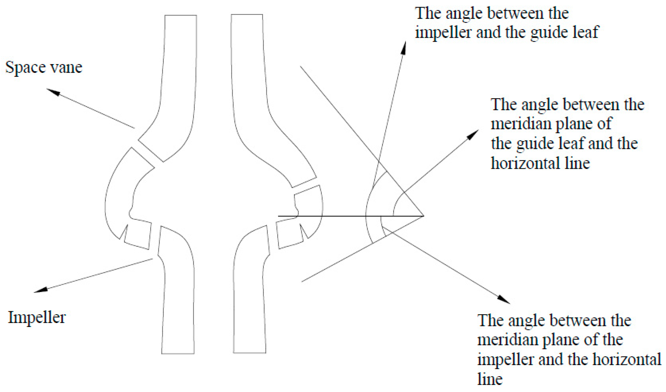
During the reflux process, the particles flow against the surface of the pump body in the flow channel, along the guide vane and guide vane front cover in the guide vane flow channel, and along the impeller blade and impeller front cover in the impeller flow channel. The reflux capacity of the pump is related to the shape of the meridian surface of the impeller and of the guide vane and the wrap angle of the vane. Figure 2 shows the axial view of the guide vane in the deep-sea lift pump space. The larger the angle between the shape of the meridian surface of the impeller and guide vane and the horizontal line, the better the reflux of particles in the axial direction. This parameter is better than the impeller; thus, the return capacity of the deep-sea pump depends on the shape of the impeller.
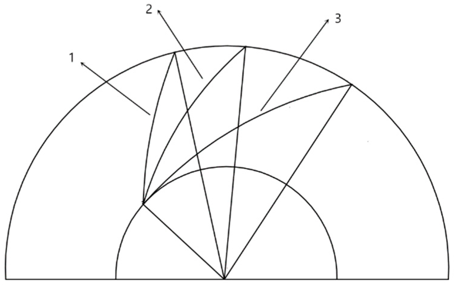
The flow of particles in the impeller flow is divided into axial flow and radial flow. The axial flow is related to the axial projection of the impeller, whereas the radial flow is related to the planar projection of the impeller. The axial projection of the impeller is related to the specific speed of the deep-sea ore pump. A low-specific-speed impeller has a narrower and longer flow channel, whereas a high-specific-speed impeller has a wider and shorter flow channel. The reflux of particles in the high-specific-speed pump is stronger than in low-specific-speed pumps. The flow of particles in the radial direction is reflected in the blade wrap angle, as shown in Figure 3. With blade wrap angle 1, the flow distance of the particles in the flow channel is shorter. Therefore, the blade recirculation property for wrap angle 1 is better than those for wrap angles 2 and 3, resulting in different impeller face profiles.
Through preliminary research on the deep-sea lifting pump, the performance of the lifting pump during the lifting process was demonstrated to be good; however, the particles were observed to have been blocked during the reflux. Furthermore, we determined that the angle is conducive to the return of the particles. Meanwhile, an impeller blade with a small wrap angle can reduce the residue of particles at the connection of the impeller guide vane during the lifting process; however, reducing the wrap angle of the impeller vane will slow lifting and reduce efficiency. Therefore, based on the technical requirements of existing projects, the following improvements are applied to the deep-sea mining pump:
- To improve the efficiency and lift of the pump, the number of impeller blades in the new deep-sea lift pump is increased.
- The recirculation of particles is ensured via the reduction of the blade wrap angle.
3. Force Analysis of Particles
In contrast to that during the lifting process of the deep-sea ore pump, the fluid is in a static state during the return flow of the particles. Because the particles do not have any power in the pump, the particles are subjected to buoyancy, gravity, additional mass force, Basset force, and fluid drag force [19].
The force due to buoyancy is
The force due to gravity is
The recirculation motion of particles in the fluid is affected by the drag force of the fluid. Because the fluid is static, it hinders the reflux of the particles. The calculation formula is
where CD is the drag coefficient:
in which
is the Reynolds number. ρf is the solid–liquid two-phase flow density, μf is the solid–liquid two-phase flow viscosity, di is the particle diameter, uf is the fluid velocity, and up is the particle velocity. The Reynolds number is determined by the velocity of the particle relative to the fluid and the particle diameter.
Additional mass force is
Basset force is
The Navier–Stokes equations are used to describe the fluid; the continuity equation is
and the momentum equation is
where
The definitions of all parameters are listed in Table 1.
With regard to calculations for particles in Lagrangian coordinate systems, the particle motion obeys Newton’s second law. The governing equations for the particles are
where F is the resultant force of the normal and tangential contact forces, and M is the resultant moment of the particle tangential and rolling frictional moments.
4. Numerical Simulation
The coupled simulation of CFD–DEM was performed using Fluent and EDEM. As a dedicated commercial software package, Fluent is commonly used for fluid calculations worldwide. With the development of Fluent, the compilation function has been developed; EDEM’s API is coupled with it, combining pure flow field and particle calculations. EDEM is a three-dimensional software package for performing particle calculations based on discrete particle science and can quickly model various parameters, such as particle shape and physical properties. Additionally, the software can accurately describe particle collisions based on Newton’s second law. In this study, the solid–liquid two-phase flow was calculated by coupling the two programs, which can accurately reflect the interaction between the effect of particles on fluids and the effect of particles on particles [20].
In the coupled calculation, the fluid and particle calculations were performed separately. First, the flow field was calculated using Fluent. After completion of the flow field iteration, the data were transferred to EDEM. The particles were used as discrete phases in EDEM to combine the flow field information. The soft ball model calculated particle collisions, performed iterative operations on particle motion, and outputted the positional information, momentum, energy, and other data for the discrete particles to Fluent. After the particle data were updated in Fluent, the next iteration was performed until the results converged [21].
In this study, the particle volume concentration and maximum particle size were set to 6% and 20 mm, respectively.
In the numerical simulation, the sedimentation velocities of the particles were as shown in Table 2.
The SST k–ω model considers the transport of the turbulent shear force against the pressure gradient boundary layer; therefore, it is more suitable for separation flow simulation. Moreover, the SST k–ω model combines the merits of the k–ω and k–ε turbulence models in the boundary layer calculations, which are accurate. Therefore, this model was selected as the calculation model in this study.
In this study, a three-dimensional model of the impeller and space vane was established using BladeGen and meshed by ICEM. Table 3 lists the impeller and space vane parameters.
Figure 4 shows the pump shaft in profile. The colored areas show the main flow path through the pump, which is the computational domain in this study.
The impeller is the main hydraulic work component of the pump. The main parameters of its hydraulic structure are the impeller inlet diameter Dj, minimum outside diameter D1, inlet installing angle β1, maximum outside diameter D2, impeller outlet width b2, outlet installing angle β2, and blade wrap angle φ. These are shown in Figure 5.
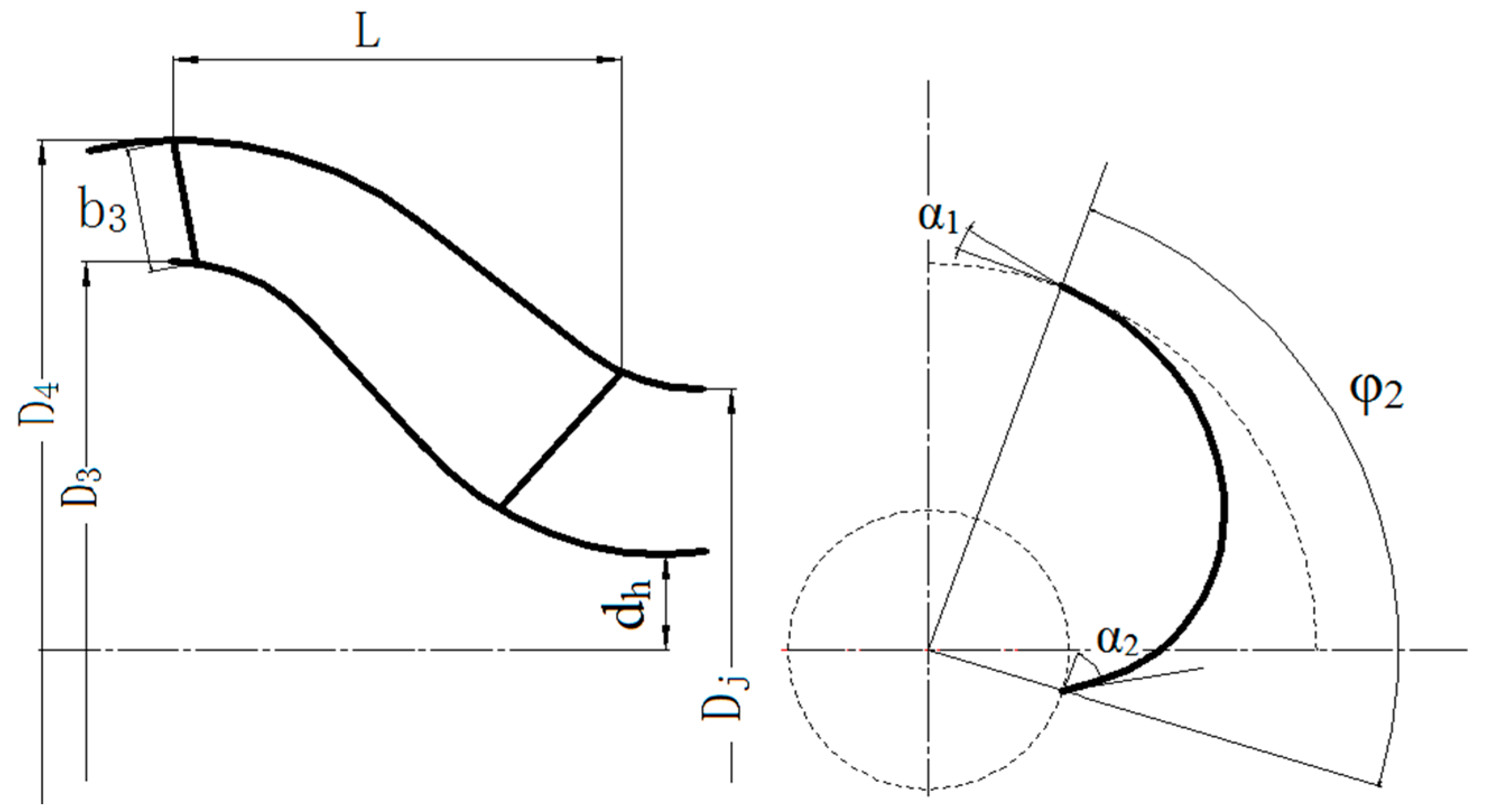
The main hydraulic structure parameters of the space guide vane are the guide vane inlet width b3, maximum inlet diameter D3, maximum outside diameter D4, inlet installing angle α1, outlet installing angle α2, and guide vane wrap angle φ2. These are shown in Figure 6.
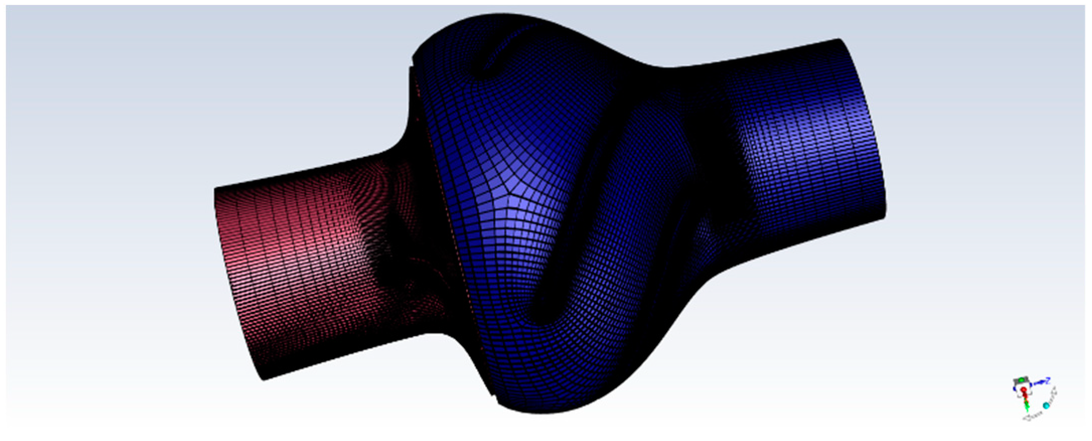
The grid for the impeller and guide vane is shown in Figure 7.
After the grid independence test, it was found that when the number of grids exceeds 1 million, the changes in the head and efficiency are small; therefore, the selected number of grids was 1.2 million. The blade angle was selected from among the following values: 105°, 110°, and 115°.
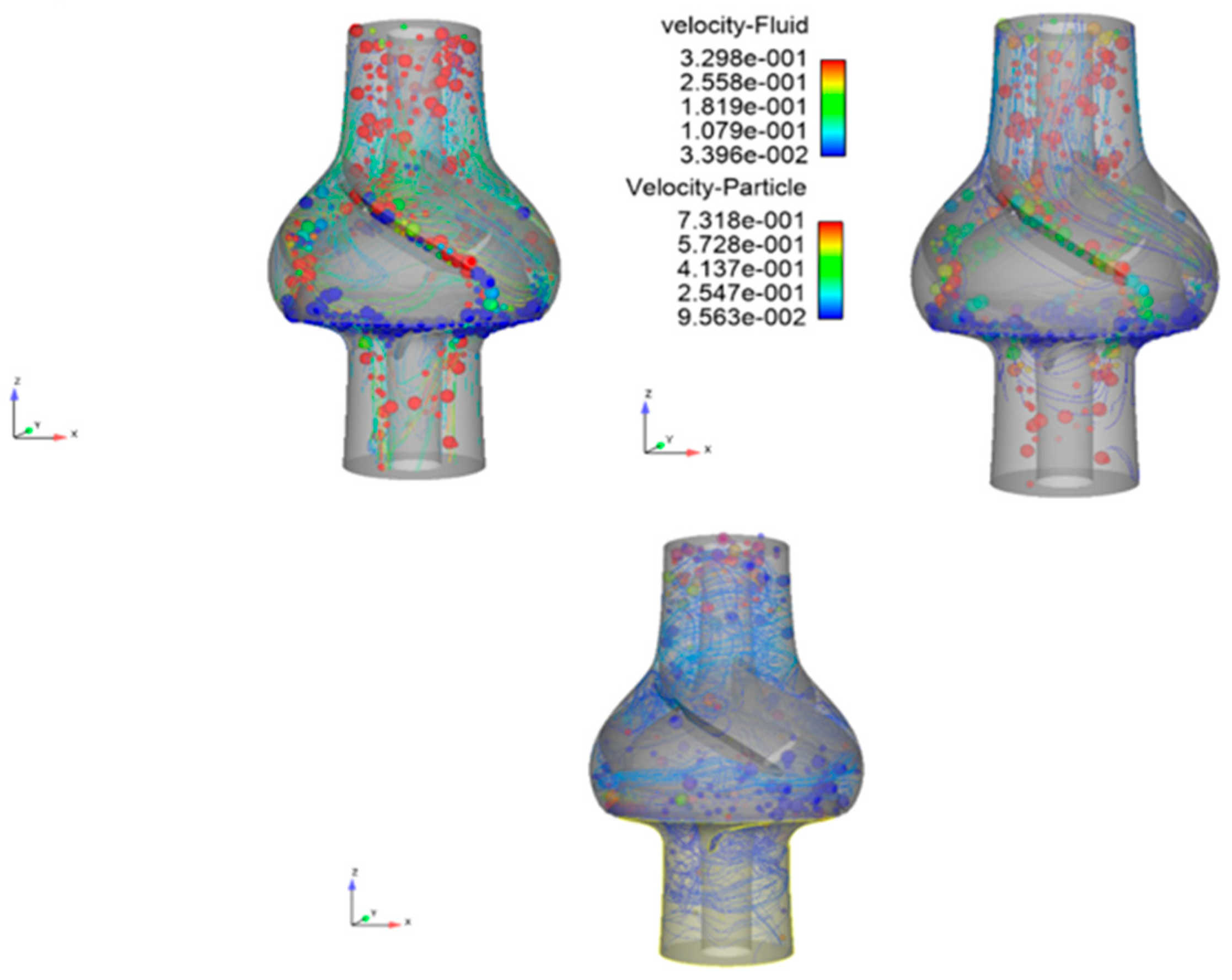
Figure 8 shows graphs of the particle velocity and flow field when blades with different wrap angles undergo reflux.
According to Figure 8, the velocity of the particles is higher than the velocity of the fluid. Furthermore, the velocity of the particles increases after the particles enter the fluid. At this point, the speed begins to decrease. After entering the impeller flow channel, the flow of particles changes as the wrap angle is increased. The larger the wrap angle, the lower the particle velocity. This occurs in the inlet extension pipe of the guide vane and outlet extension pipe of the impeller, whereas the minimum speed occurs at the connection between the impeller and the guide vane. From the streamline line, the streamline motion law for the small wrap angle can be inferred. The reflux after the impeller flow channel is not smooth, which affects the streamline of the entire flow channel. Furthermore, the figure shows that when the wrap angle is small, particles 20 mm in size can flow out of the impeller flow channel smoothly, whereas when the wrap angle is increased, particles of this size start to flow back from the impeller, and the flow becomes more difficult.
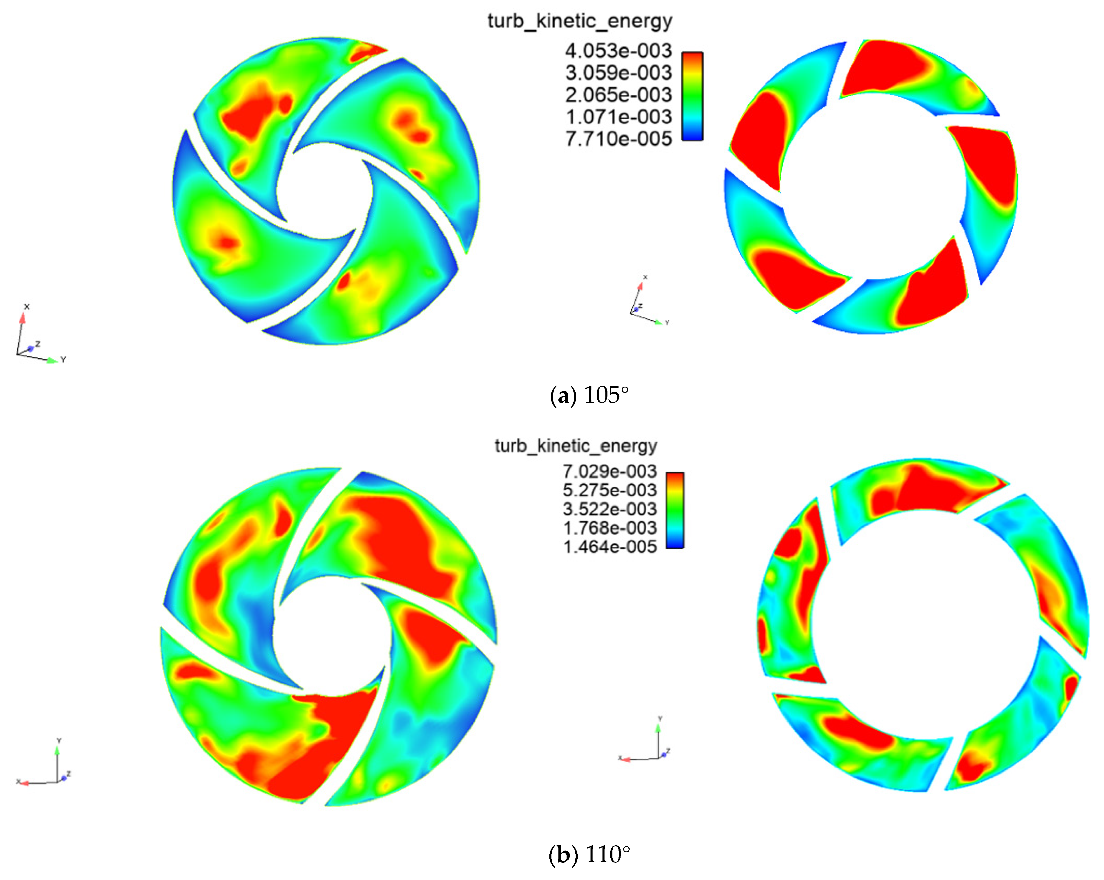
A study on the turbulent kinetic energy can better elucidate the turbulence characteristic of solid-liquid two-way flow in the impeller and guide vane. Figure 9 shows a schematic diagram of the turbulent kinetic energy of impeller guide vanes for different wrap angles.
As shown in Figure 6, at low particle velocities, most of the particles return to the lower cover plate of the impeller after entering the impeller flow channel. Therefore, the particles flow in the impeller flow channel as a bed mass. As the wrap angle increases, the turbulent kinetic energy increases, indicating that the turbulent intensity increases. The increase in turbulent kinetic energy results in a turbulent flow field, which reduces the recirculation of the particles.
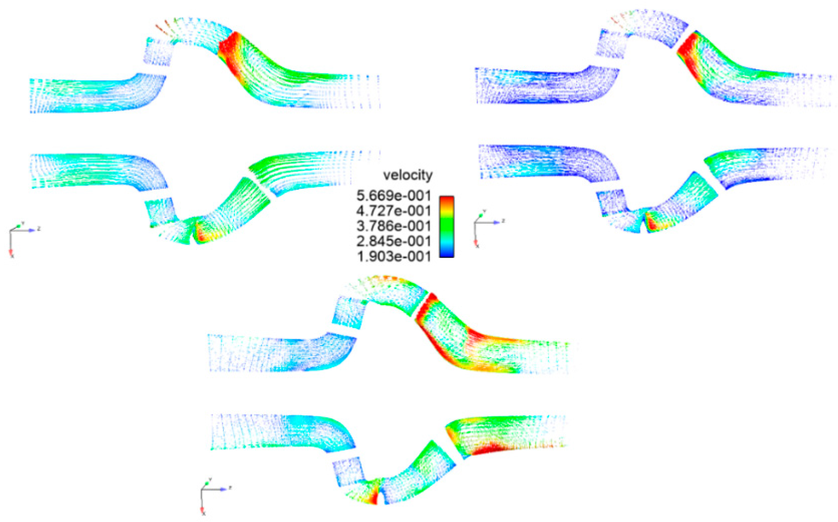
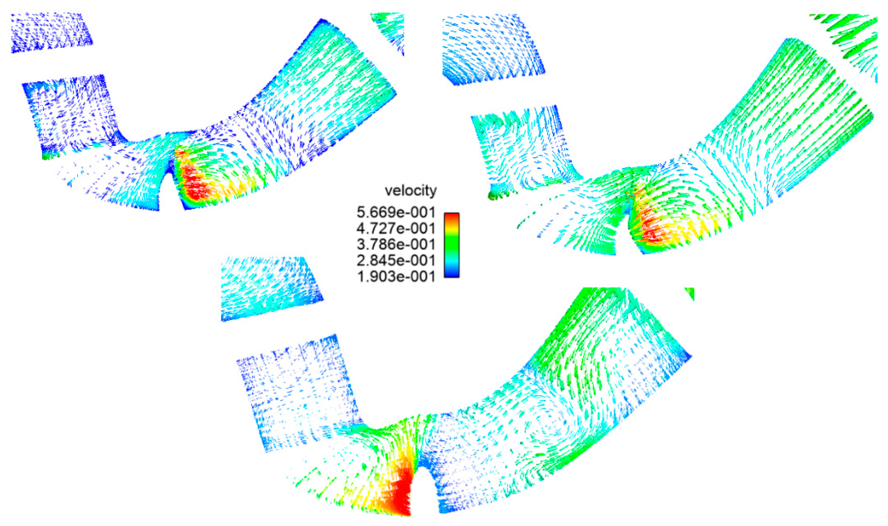
The secondary flow of particles, which is an important factor in reflux, was also examined. Figure 10 shows particle velocity vector diagrams for the full flow channel.
According to Figure 10, there is a secondary flow of particles on the guide vane flow channel and at the connection between the impeller and the guide vane. The occurrence of a secondary flow of particles further reduces the recirculation capacity of the particles, and as the wrap angle increases, the value of the secondary particle flow increases; thus, it is analyzed separately.
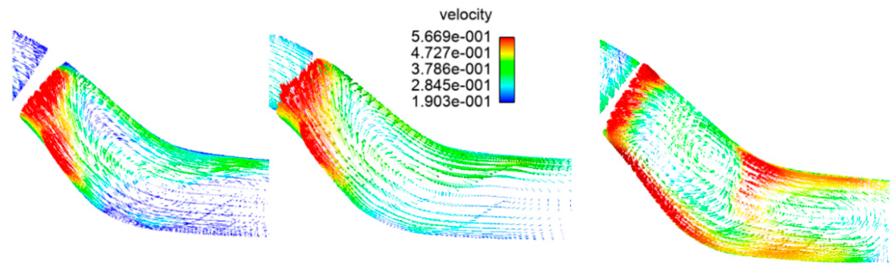
Figure 11 and Figure 12 visualize the distributions of the secondary flow of particles in the guide vane and at the connection between the impeller and the guide vane, respectively.
After entering the guide vane, the particles move along the pressure surface at the guide vane, and a secondary flow of particles is generated because the pressure surface has a certain angle. The reason for this phenomenon is that when the wrap angle is large, the recirculation of the particles at the impeller is poor, resulting in a change in pressure directly affecting the secondary flow of particles at the guide vane; the occurrence of this secondary flow reduces the recirculation performance of the particles.
After the particles enter the impeller from the guide vane, the distribution of the secondary flow of particles changes because of the different wrap angles of the impeller. At the connection with a larger wrap angle, it can be observed that there are additional vortices in the secondary flow of the particles. This reduces the ability of the particles to reflux, increasing the likelihood of particle aggregation.
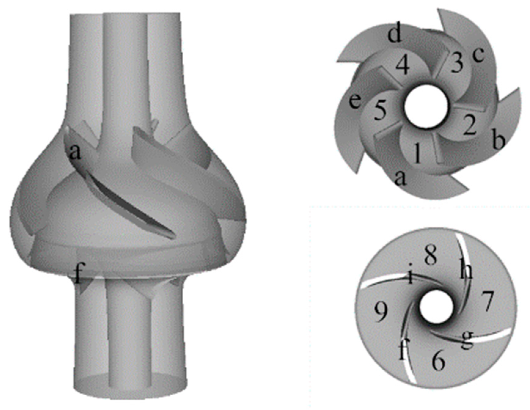
Figure 13 shows the positional relationship between the guide vane flow channel and impeller. The guide vane blades are marked as a, b, c, d, and e; the guide vane flow channels are marked as 1, 2, 3, 4, and 5; the impeller blades are marked as f, g, h, and i; and the impeller channels are marked as 6, 7, 8, and 9.
As time progresses, the number of particles in the deep-sea lifting test pump continues to increase. As the number of particles in the deep-sea lifting test pump gradually increases, the particles at the lower end are squeezed by the particles in the upper section, and it becomes easier to pass through the deep-sea lifting test pump. The particle depositions in the different guide vanes and impeller channels in the pump are also different. Figure 14 visualizes the changes in the number of particles in the guide vanes and impeller channels over time.
According to Figure 14, in impellers with different wrap angles, the numbers of particles in the five flow passages entering the guide vane from the inlet extension section are typically the same. The number of particles in guide vane runner 3 is the largest, while that in guide vane runner 1 is the least; the rest of the guide vane runners (2, 4, and 5) are between the two. After the particles in the different guide vane flow channels enter the impeller flow channel, the flow conditions of the particles change. The particles in guide vane flow channel 1 flow into impeller flow channel 6 from the pressure surface of guide vane blade a, and flow down along impeller blade f. The exit of the flow from the pump is shorter. In impeller flow channel 6, there are still a small fraction of particles flowing in from guide vane flow channel 5 along the suction surface of guide vane blade a; however, the number of particles is small, and the particle diameter is small; thus, the particles in impeller flow channel 6 are not affected. Reflux has no effect. The particles in guide vane flow channel 4 flow back through impeller flow channel 9, whereas most of the particles in guide vane flow channel 5 will flow into impeller flow channel 9 through the tail of guide vane blade e, which will affect impeller flow channel 9. The reflux of particles in the impeller forms an obstacle, and after the particles stay at the outlet of impeller flow channel 9, a fraction of the particles in guide vane flow channel 5 are forced to enter impeller flow channel 9. The reflux of particles in guide vane flow channel 5 from impeller flow channels 6 and 9 is significantly hindered, and the passage of the particles in guide vane flow channel 5 is poor. The properties of the remaining guide vane runners are between those of runners 1 and 5. As the wrap angle of the impeller blades increases, this trend becomes more evident, and the particles in impeller flow channel 9 aggregate, which will eventually cause the blockage of impeller flow channel 9. After impeller flow channel 9 is blocked, it will affect the flows in the guide vane flow channels.
5. Testing
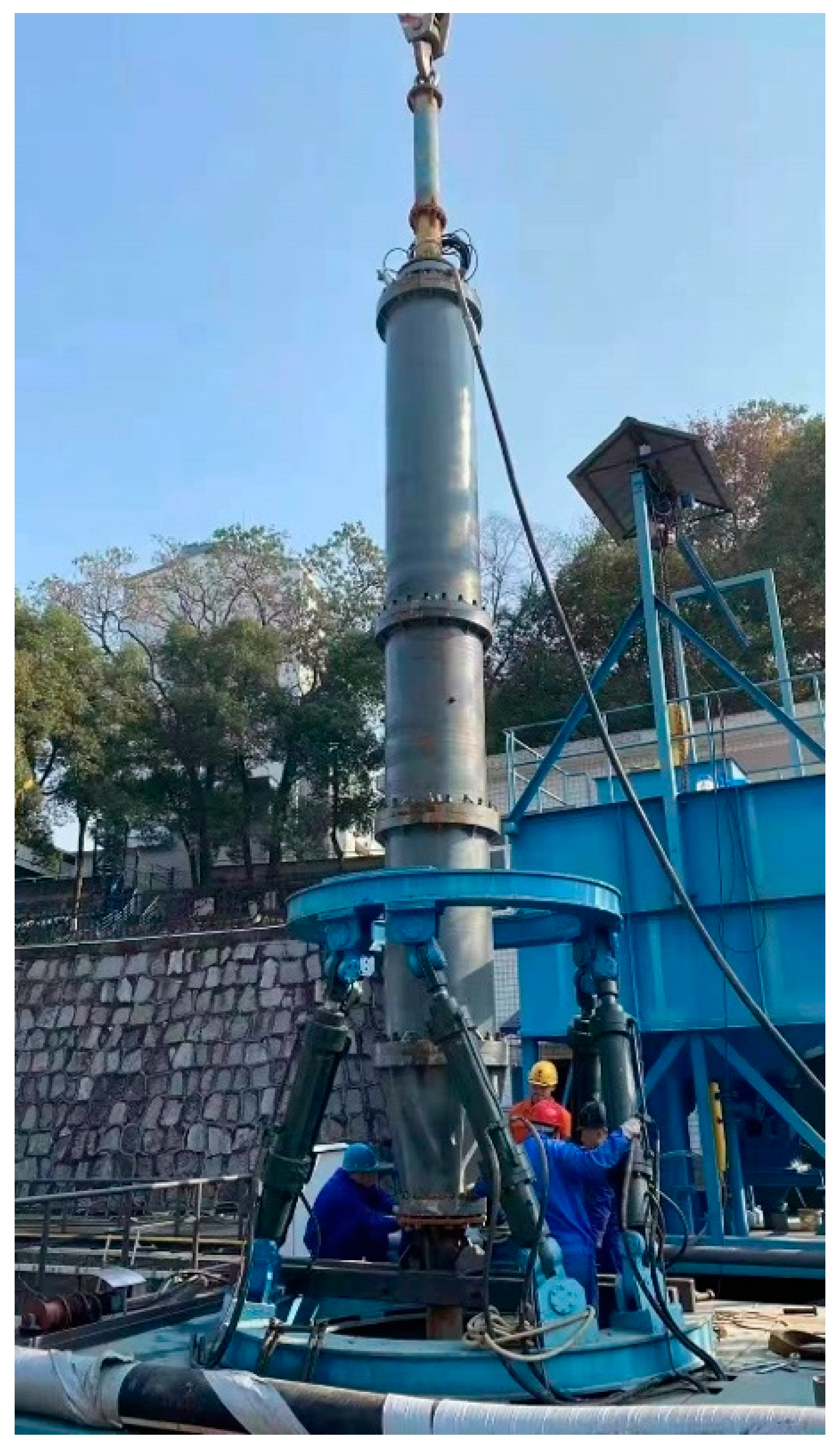
The phenomenon of inter-stage matching occurs during the lifting process of the pump. Therefore, to ensure the smooth progress of the sea trial of the deep-sea lifting pump and to verify the numerical simulation model developed in this study, a deep-sea lifting pump was used for the test. The solid–liquid two-phase fluid concentration was 6%, whereas the blade wrap angle was 110°. Figure 15 shows the pump.
The experiments were conducted with clay-fired simulated nodule particles, as shown in Figure 16. In particular, 88.86% of the nodules by mass had diameters between 8 and 13 mm; the statistical mean of particle diameters was approximately 10 mm; and the largest particle diameter was 25 mm. The density of simulated nodules was 1.91 g/cm3, which is approximately equal to that of natural nodules.
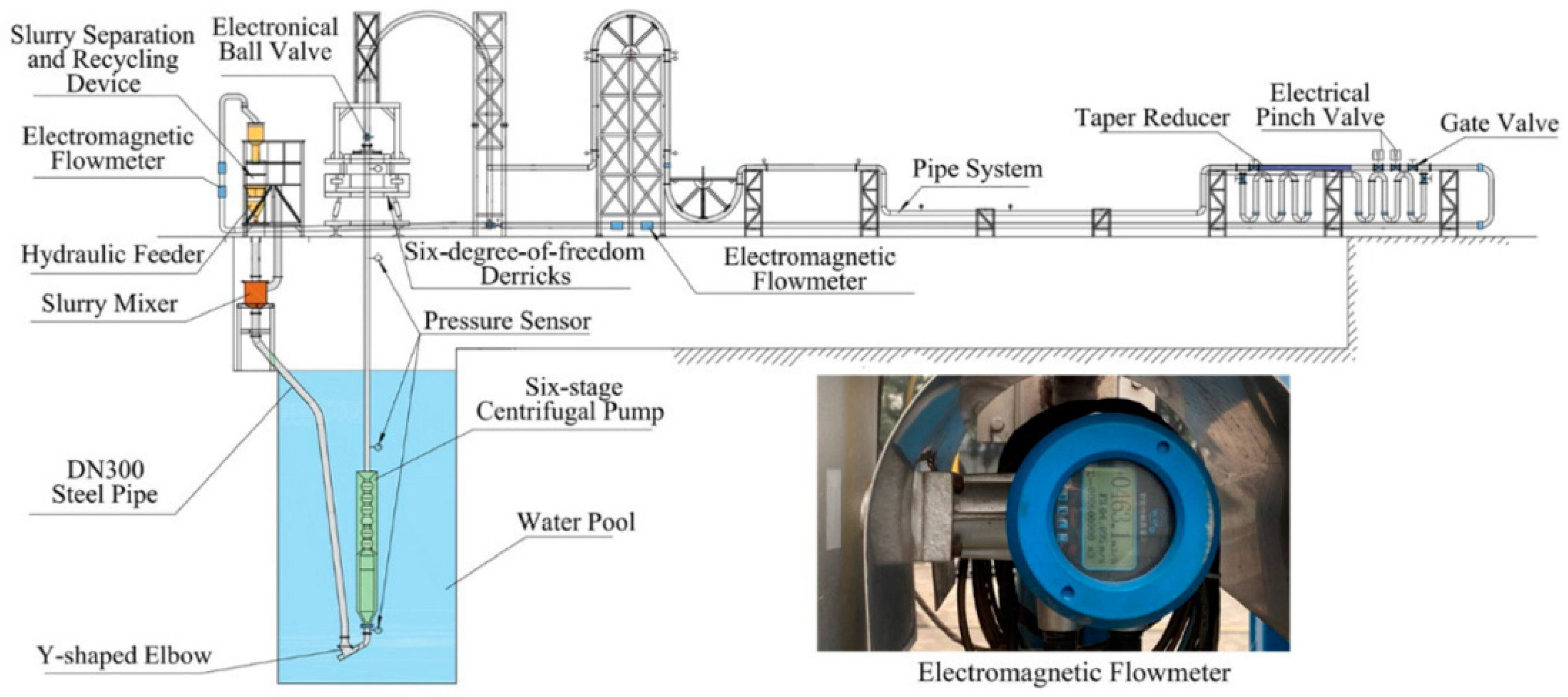
As shown in Figure 17, the pump was installed in a pool with a maximum depth of 20 m to avoid cavitation and was fixed on a six-degree-of-freedom derrick through pipes. The maximum flow load of the test system was 1000 m3/h. A diesel generator was used to power the system with a maximum power load of 1000 kW. The maximum continuous feeding capacity of the slurry feeder was 50 kg/s. The pressure sensor was installed at the inlet and outlet of the pump. Two electromagnetic flowmeters were installed on horizontal and vertical pipelines with a flow range of 100–1000 m3/h.
In the test, under the flow of 430 m3/h, the speeds of 1100 rpm, 1200 rpm, 1300 rpm, and 1450 rpm were selected. The results are shown in Table 4. Note that
where ω3 is the rotational speed and M is the impeller torque, both of which can be obtained in the post-processing of the numerical simulation.
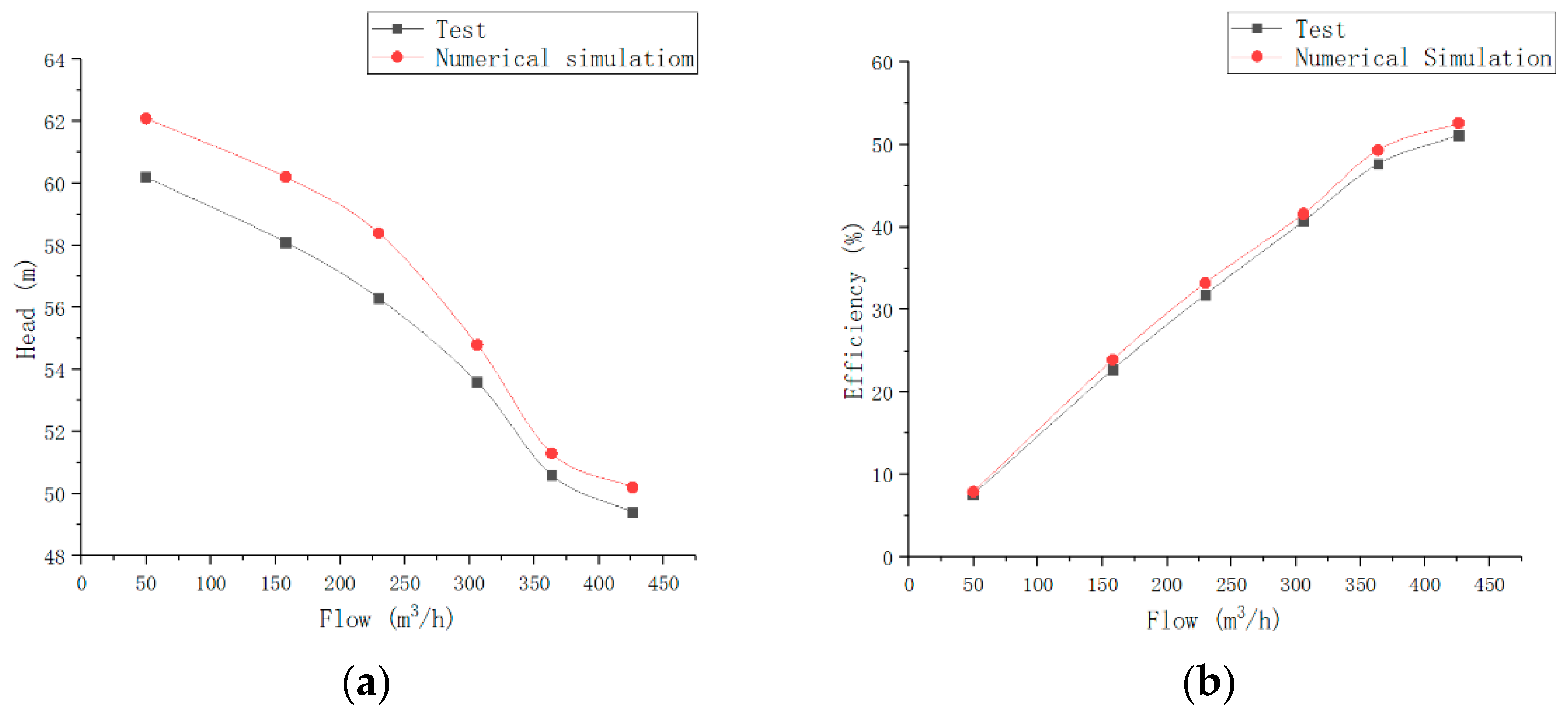
It can be observed from Table 4 that the simulation results are significantly close to the experimental results. The simulation head and efficiency are the same as those in the experiment. Furthermore, it can be observed from the test that with an increase of rotational speed, the head and efficiency gradually increase. For a rotational speed of 1450 rpm, the head and efficiency of the lifting pump at different flow rates were measured. The test results and numerical simulation results are shown in Figure 18.
According to Figure 18, as the flow rate is increased, the lift of the ore pump gradually decreases, and the efficiency gradually increases. When the rated flow rate is reached, both the lift and efficiency of the ore lift pump fulfill the design requirements, indicating that for the hydraulic performance, this improvement is reasonable. The resulting values from the numerical simulation are larger than those from the experiment because the particles in the numerical simulation adopt a standard spherical shape. Therefore, the resistance received by the particles in the test was relatively low, which translated to an experimental error. Nonetheless, the experimental error is within 8%; thus, the simulation results are credible.
The reflux test was provided by Changsha Research Institute of Mining and Metallurgy. The ore particles were recovered through a mesh particle collection device installed at the bottom of the two-stage pump. During the test, the two-stage pump and particle collection device were installed in the water, and the particles passed through the pump outlet. As shown in Figure 19, there was particle blockage at the pump outlet; in particular, one channel was blocked by particles. The experimental results are typically the same as the numerical simulation results.
6. Conclusions
In this study, we investigated the reflux velocities of particles and fluids in a deep-sea lifting test pump and determined that the velocity of the particles is higher than that of the fluid. Furthermore, the velocity of the particles increases after the particles enter the fluid, and the larger the wrapping angle, the lower the particle velocity. When the wrap angle is small, 20-mm particles can flow out of the space vane channel smoothly, but after the wrap angle increases, it becomes more difficult for the 20-mm particles to flow back from the impeller.
Research on the particle distribution in the flow channel of the deep-sea lifting test pump revealed that the distributions of particles are typically the same between the impellers with different wrap angles. As the wrap angle is increased, the number of particles remaining in the impeller flow channel gradually increases, and the recirculation of particles decreases. Impellers with different wrap angles have different numbers of particles at the connection. The greater the wrap angle of the impeller blades, the higher the number of particles deposited there. Eventually, this causes particle blockage in a flow channel.
Through an investigation on the return flow of the blade wrap angle, it was determined that the smaller the wrap angle of the impeller blade, the better the return flow of the particles. However, if the wrap angle of the impeller blade is excessively small, the lift and efficiency will be excessively low. The number of blades can ensure the lift efficiency as well as improve the particle recirculation. However, in the experiments and numerical simulations, it was observed that the particles would still block the flow channel during reflux. Therefore, it is necessary to study the influence of additional factors on the reflux characteristics of the deep-sea lift pump.
The testing demonstrated that the head and efficiency can meet the design requirements. When the speed of the deep-sea lifting pump was 1450 rpm, the lift and efficiency were the highest, as was the fluid velocity, and the particles could obtain more energy from the flow field. This confirms that the design of the flow channel is reasonable and can ensure the transport of particles. However, although the return flow capacity of the pump is improved over that of the previous design, flow channel blockage still occurs. Therefore, it is necessary to continue to study other key parameters to achieve the goal of the complete return flow of particles.
Through this design optimization process, the head and efficiency can meet the design requirements, and the reflux ability is improved over that of the original pump.
Author Contributions
Y.L. and X.H.; methodology, Y.L.; software, validation, formal analysis; investigation; resources, data curation, writing—original draft preparation; writing—review and editing, X.H.; visualization; supervision; project administration; funding acquisition. All authors have read and agreed to the published version of the manuscript.
Funding
National Key R&D Program of China: Development and Test of Lifting Pump for Deep Sea Mining Test Project: 2016YFC0304103-4; Changsha Municipal Science and Technology Project: kq2203004.
Conflicts of Interest
The authors declare no conflict of interest.
References
- Kato, Y.; Fujinaga, K.; Nakamura, K.; Takaya, Y.; Kitamura, K.; Ohta, J.; Toda, R.; Nakashima, T.; Iwamori, H. Deep-sea mud in the Pacific Ocean as a potential resource for rare-earth elements. Nat. Geosci. 2011, 4, 535–539. [Google Scholar] [CrossRef]
- Zou, W.; Liu, R.; Liu, S. Study on lifting motor pumps for coarse particle slurry in sea bed mining. China Mech. Eng. 2019, 30, 2939–2944. [Google Scholar]
- Cundall, P.A.; Hart, R.D. Development of Generalized 2-D and 3-D Distinct Element Programs for Modeling Jointed Rock; Miscellaneous Paper SL-85-1 for US Army Corps of Engineers; National Technical Information Service: Springfield, VA, USA, 1985.
- Cundall, P.A.; Strack, O.D.L. The Distinct Element Method as a Tool for Research in Granular Media, Part II; Report on NSF Grant ENG76-20711; University of Minnesota: Minnesota, MN, USA, 1979. [Google Scholar]
- Technology Research Association of Ocean Mineral Resources Mining System (TRAM). TRAM R&D of Manganese Nodule Mining Systems; Japan Slurry Transport Association: Tokyo, Japan, 1991. [Google Scholar]
- Kang, Y.; Liu, S. Summary of research on lifting system of deep-sea mining. J. Mech. Eng. 2021, 57, 232–243. [Google Scholar] [CrossRef]
- Tan, M.; Lian, Y.; Liu, H.; Wu, X.; Ding, R. Visualizing test on the pass-through and collision characteristics of coarse particles in a double blade pump. Int. J. Nav. Archit. Ocean Eng. 2018, 10, 1–8. [Google Scholar] [CrossRef]
- Ma, W.; Lodewijks, G.; Schott, D. Analysis of a green transport plant for deep sea mining systems. J. Min. Sci. 2018, 54, 254–269. [Google Scholar] [CrossRef]
- Miedema, S.A. A head loss model for homogeneous slurry transport for medium sized particles. J. Hydrol. Hydromech. 2015, 63, 1–12. [Google Scholar] [CrossRef] [Green Version]
- Miedema, S.A. The heterogeneous to homogeneous transition for slurry flow in pipes. Ocean Eng. 2016, 123, 422–431. [Google Scholar] [CrossRef] [Green Version]
- Hu, Q.; Zou, L.; Lv, T.; Guan, Y.; Sun, T. Experimental and numerical investigation on the transport characteristics of particle-fluid mixture in Y-shaped elbow. J. Mar. Sci. Eng. 2020, 8, 675. [Google Scholar] [CrossRef]
- Liu, S.; Li, Y.; Hu, X. Effect of particle volume fraction on the performance of deep-sea mining electric lifting pump based on DEM-CFD. J. Mech. Eng. 2020, 56, 257–264. [Google Scholar] [CrossRef]
- Liu, L. Research on the Dynamic Characteristics of Solid–Liquid Two-Phase Flow in Deep-Sea Mining Hydraulic Lifting. Ph.D. Thesis, Shanghai Jiao Tong University, Shanghai, China, 2019. [Google Scholar]
- Xu, H.; Zeng, Y.; Chen, Q.; Wu, B. Numerical simulation of particle flow in deep-sea mining slurry pump. J. Cent. South Univ. Nat. Sci. Ed. 2017, 48, 84–90. [Google Scholar] [CrossRef]
- Hu, Q.; Chen, J.; Deng, L.; Liu, S. CFD-DEM coupled simulation and experimental study of deep-sea lifting mine pump under extreme working conditions. Chin. J. Nonferrous Met. 2021, 31, 2926–2937. [Google Scholar] [CrossRef]
- Yingjie, G.; Li, Z.; Hao, Z.; Yougang, B.; Zongbing, Y. Backflow performance of ore particles in deep-sea mineral slurry pump. J. Harbin Eng. Univ. 2021, 42, 1557–1565. [Google Scholar]
- Yingjie, W.; Ning, Y.; Xing, J. Experimental study on backflow of particles in deep-sea lifting system. Ocean Eng. 2012, 30, 100–104. [Google Scholar]
- Li, Y.; Liu, S.; Hu, X. Research on reflux in deep-sea mining pump based on DEM-CFD. Mar. Georesour. Geotechnol. 2020, 38, 744–752. [Google Scholar] [CrossRef]
- Hu, Q.; Chen, J.; Deng, L.; Kang, Y.; Liu, S. CFD-DEM simulation of backflow blockage of deep-sea multistage pump. J. Mar. Sci. Eng. 2021, 9, 987. [Google Scholar] [CrossRef]
- Rashidi, S.; Esfahani, J.A.; Ellahi, R. Convective heat transfer and particle motion in an obstructed duct with two side by side obstacles by means of DPM model. Appl. Sci. 2017, 7, 431. [Google Scholar] [CrossRef] [Green Version]
- Chen, Q.; Xiong, T.; Zhang, X.; Jiang, P. Study of the hydraulic transport of non-spherical particles in a pipeline based on the CFD-DEM. Eng. Appl. Comput. Fluid Mech. 2020, 14, 53–69. [Google Scholar] [CrossRef]
Figure 1.
50-mm particles plugging in reflux.

Figure 2.
Axial view of space guide vane of deep-sea mining pump.

Figure 3.
Profiles of different impeller working surfaces.

Figure 4.
Axial section of impeller and diffuser.

Figure 5.
Main structural parameters of the impeller.

Figure 6.
Main structural parameters of the guide vane.

Figure 7.
Grid for impeller and vane.

Figure 8.
Particle velocity and flow field diagrams for different wrapping angles during reflux.

Figure 9.
Turbulent kinetic energy distributions of impeller guide vanes at different rotational speeds.
Figure 9.
Turbulent kinetic energy distributions of impeller guide vanes at different rotational speeds.


Figure 10.
Full runner velocity vector diagrams.

Figure 11.
Distributions of secondary flows of particles in guide vanes.

Figure 12.
Distributions of secondary flows of particles at junction of impeller and guide vane.

Figure 13.
Positional relationship between guide vane and impeller.

Figure 14.
Variations in number of impeller particles for different wrap angles in guide vane and impeller channel with respect to time.
Figure 14.
Variations in number of impeller particles for different wrap angles in guide vane and impeller channel with respect to time.


Figure 15.
Deep-sea pump.

Figure 16.
Test particles.

Figure 17.
Experimental system layout.

Figure 18.
Test results and numerical simulation results: (a) head; (b) efficiency.

Figure 19.
Particle blockage.


Table 1.
Equation parameters.
| Parameter | Definition |
|---|---|
| ρ | Fluid volume |
| α | Volume fraction of the fluid |
| ui, uj | Cartesian coordinates of the velocity component |
| Fpf | Interaction forces between continuous and discrete phases |
Table 2.
Particle size distributions and physical properties.
| Particle Size (mm) | Yield after Crushing (%) | Settling Velocity (m/s) |
|---|---|---|
| 10–20 | 50.8 | 0.613 |
| 5–10 | 26.9 | 0.53 |
| 0–5 | 22.3 | 0.41 |
Table 3.
Parameters of the impeller and the space vane.
| Impeller Parameter | Value | Space Vane Parameter | Value |
|---|---|---|---|
| Number | 4 | Number | 5 |
| Inlet diameter | 235 mm | Maximum inlet diameter | 516 mm |
| Maximum outside diameter | 425 mm | Minimum inlet diameter | 395 mm |
| Minimum outside diameter | 395 mm | Maximum outside diameter | 260 mm |
| Outlet width | 60 mm | Minimum outside diameter | 95 mm |
| Inlet installing angle | 35° | Inlet installing angle | 12° |
| Outlet installing angle | 32.5° | Outlet installing angle | 85° |
| Blade wrap angle | 105°, 110°, 115° | Blade wrap angle | 95° |
Table 4.
Test results and simulation results.
| Rotational Speed (rpm) | Head (m) | Efficiency (%) | |
|---|---|---|---|
| Test | 1100 | 44.6 | 40.68 |
| Simulation | 1100 | 45.7 | 41.81 |
| Test | 1200 | 46.8 | 43.98 |
| Simulation | 1200 | 48.3 | 44.94 |
| Test | 1300 | 47.9 | 45.81 |
| Simulation | 1300 | 48.7 | 47.32 |
| Test | 1450 | 49.4 | 51.11 |
| Simulation | 1450 | 50.2 | 52.62 |
Publisher’s Note: MDPI stays neutral with regard to jurisdictional claims in published maps and institutional affiliations. |
© 2022 by the authors. Licensee MDPI, Basel, Switzerland. This article is an open access article distributed under the terms and conditions of the Creative Commons Attribution (CC BY) license (https://creativecommons.org/licenses/by/4.0/).
Share and Cite
MDPI and ACS Style
Li, Y.; Hu, X. Design Optimization of Deep-Sea Lift Pump Based on Reflux Characteristics. Machines 2022, 10, 520. https://0-doi-org.brum.beds.ac.uk/10.3390/machines10070520
AMA Style
Li Y, Hu X. Design Optimization of Deep-Sea Lift Pump Based on Reflux Characteristics. Machines. 2022; 10(7):520. https://0-doi-org.brum.beds.ac.uk/10.3390/machines10070520
Chicago/Turabian StyleLi, Yuanwen, and Xiaozhou Hu. 2022. "Design Optimization of Deep-Sea Lift Pump Based on Reflux Characteristics" Machines 10, no. 7: 520. https://0-doi-org.brum.beds.ac.uk/10.3390/machines10070520
Note that from the first issue of 2016, this journal uses article numbers instead of page numbers. See further details here.