Article

A Magnetic Abrasive Finishing Process with an Auxiliary Magnetic Machining Tool for the Internal Surface Finishing of a Thick-Walled Tube

1
College of Physics and Mechanical Engineering, Longyan University, Longyan 364000, China
2
Key Laboratory E&M, Zhejiang University of Technology, Hangzhou 310014, China
3
Engineering Research Center of Brittle Materials Machining, Huaqiao University, Xiamen 361000, China
4
Graduate School of Engineering, Utsunomiya University, Utsunomiya 321-8585, Japan
*
Author to whom correspondence should be addressed.
Submission received: 18 May 2022 / Revised: 16 June 2022 / Accepted: 20 June 2022 / Published: 29 June 2022

Abstract

:
This paper proposes a novel magnetic abrasive finishing (MAF) process that uses an auxiliary magnetic machining tool for the internal surface finishing of a thick-walled tube. The auxiliary magnetic machining tool and external poles form a closed magnetic field circuit. Thus, a stronger magnetic force can be generated during the process. In the current study, we focus on analyzing the distribution of the magnetic field and magnetic flux density and investigating the finishing characteristics of a mixed magnetic abrasive finishing process and speed of relative revolutions. Based on the finishing characteristics, we also conduct a stage-by-stage finishing process by changing the combinations of the mixed magnetic abrasive finishing process. The finishing quality of the internal surface was mainly evaluated by the measured roundness and surface roughness. The experimental results show that the roundness and surface roughness Ra are affected when the total amount of WA abrasive and iron powder is too much; a better surface roughness could be obtained when the difference in the speed of relative revolutions is considerable, but the roundness is the worst. Furthermore, the original roundness measurement of 270 µm can reach 10 µm, and the surface roughness Ra can increase from an original surface roughness of 4.1 µm to reach 10 nm after 105 min of the stage-by-stage finishing process.

1. Introduction

With the development of industrial manufacturing technology, certain thick-walled tubes are widely used in industrial production, such as the transportation of high-purity biomedical liquid, engineering, energy storing, food manufacturing, and many other fields. For the internal surface of welded stainless-steel tubes with a great surface roughness, the bacterium, dirt, or liquid easily remain in the tiny gaps or pits of the internal surface, and they are cleaned in different ways. This seriously affects the purity of the stored liquid and the safety of food or biomedical manufacturing [1,2,3]. The accumulated dirt may also cause corrosion, cracks, and even lead to leakage or explosions. Furthermore, the internal wall surface with slight unevenness can cause local stress concentrations when the liquid passes through the tube. Thus, the internal surface accuracy of tubes in container and piping systems is in increasing demand to prevent the deposition and residue of pollutants.
Since the magnetic field has penetrating characteristics, the MAF process can be used to not only finish the outer surface of the workpiece, but also its inner surface [4,5,6,7]. Shinmura and Yamaguchi firstly proposed using MAF technology for the internal surface finishing process of a stainless-steel tube in 1995, and the experimental results implied that MAF technology was able to achieve uniform internal surface finishing process for tube workpieces [8]. Subsequently, they also used MAF technology to engage in related research on the internal surface finishing process of some special-shaped tubes and microtubes [9,10]. Although the MAF process was proven to be effective for finishing the internal surface of tubes, the problem of the insufficient finishing pressure causing low finishing efficiency was found by some analyses and experiments [11,12,13]. In order to solve this problem, some researchers engaged in optimizing the finishing parameters and improving the finishing technique. Zhang et al. proposed a new method of increasing the finishing pressure by using the “pressuring bag” in the finishing system [14]. Yamaguchi et al. suggested using a multiple pole-tip system with a high speed (up to 30,000 min−1); the experimental results proved that finishing efficiency can be improved by this method [15,16]. Furthermore, Muhamad et al. developed a compound polishing method of the EMAF process from the perspective of changing the finishing characteristics of workpiece materials; the experimental results showed that both the quality of the internal surface and the finishing efficiency can be improved, and the finishing efficiency can be improved by more than 80% [17,18,19].
In addition to MAF technology, there are many other machining methods for the internal surface [20]. Wang et al. proposed the ion beam figuring method for polishing the synchrotron X-ray mirror; the results showed that 1.1 nm in RMS of the residual form error was obtained on the clear aperture with the size of 5 mm × 50 mm [21]. Wang et al. developed multi-jet polishing for polishing the freeform surfaces, which, when compared to single fluid jet polishing, can obtain a higher material removal rate. Additionally, this polishing method can achieve ultra-precision polishing with nanometer/sub-nanometer scale surface roughness and high form accuracy [22]. Boschetto et al. conducted the experimental investigation on the barrel finishing process of a selective laser-melted Ti6Al4V. The surface roughness of the Ti6Al4V was reduced from 3 μm to 0.3 μm after 48 h of the barrel finishing process. Furthermore, the radius of some sharp edge was smoothed, but the initial radius increased from 93.7 μm to 847.2 μm [23].
In this study, we focus on researching the machining mechanism and investigating the polishing parameters in order to improve the inner surface accuracy of a workpiece and machining efficiency, as compared to the traditional MAF process. An auxiliary magnetic machining tool is used to form an “N-S-N-S” closed magnetic field circuit with the external poles. Compared with the traditional MAF process, since the magnetic resistance is lowered in the closed magnetic field circuit, the magnetic force can be improved considerably. Hence, the magnetic-assisted machining method is more suitable for finishing the internal surface of a thick-walled tube. Considering the service life of magnetic abrasive particles, they are changed after each finishing stage (15 min). Moreover, the change in the roundness and surface roughness Ra are evaluated by a roundness meter (Roncom 40C) and a contact surface roughness meter (SE-2300) after each finishing stage.

2. Methods and Experimental Procedure

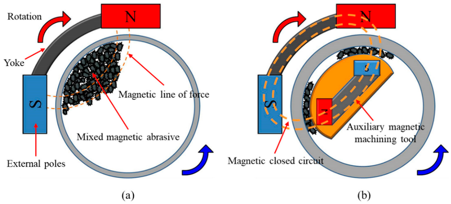
2.1. Machining Principle

The machining principle of the traditional magnetic abrasive finishing process for a thin-walled tube workpiece is shown in Figure 1a. Since the polishing pressure was generated by the magnetic field force of external poles, the mixed magnetic abrasive was attracted to the internal surface of the tube. When the external poles and tube workpiece performed a relative rotary motion, a relative friction was produced between the magnetic abrasive particle and internal surface of the tube. Hence, the precision finishing of the internal surface could be achieved. If the size of the magnetic abrasive particle is increased, the polishing pressure can also be increased. Although the material removal efficiency can be improved when the polishing pressure increases, the surface roughness is difficult to lower. Therefore, the polishing pressure of a traditional magnetic abrasive finishing process is obviously insufficient for the internal surface finishing process of a thick-walled tube. In this study, an auxiliary magnetic machining tool was stuffed in the thick-walled tube and turned with the external magnetic pole, as shown in Figure 1b. The auxiliary magnetic machining tool and external poles formed an “N-S-N-S” closed magnetic field circuit, so the strength of the magnetic field’s force was stronger than that of the traditional magnetic abrasive finishing process. The mixed magnetic abrasive was located between the internal surface of the tube and auxiliary magnetic machining tool. Thus, the efficient precision finishing process of the internal surface could be realized.

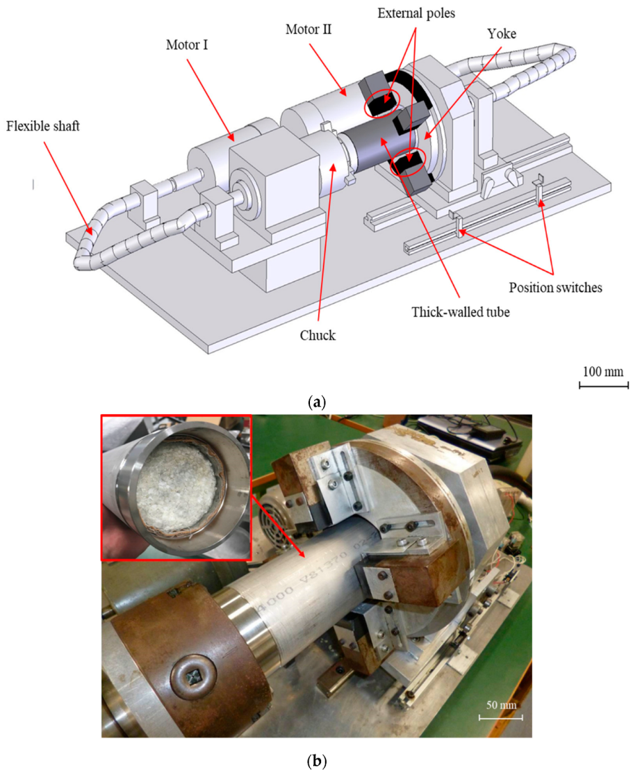
2.2. Experimental Setup and Auxiliary Magnetic Machining Tool

The three-dimensional diagram of the equipment and the external view of the experimental setup are, respectively, shown in Figure 2a,b. There are two motors in this equipment. Motor I drives the chuck to perform a rotational movement through coupling with a flexible shaft. The tube workpiece is fixed by the three-jaw chuck to perform a synchronous rotational movement. The rotational units of the magnetic poles are composed of four ferrite magnets (50 × 35 × 26 mm) and located on the outside of the tube workpiece. They are arranged in the type of “N-S-S-N” and fixed on the yoke. In this way, two pairs of “N-S” closed magnetic field circuit form around the “tube wall” of the workpieces. Motor II controls the rotational direction and speed of the external magnetic poles. The rotating device of the magnetic poles reciprocates along the axis of the tube workpiece through a pair of position switches. The mixed magnetic abrasive injected into the tube follows with the movement of the external magnetic poles to create friction on the internal surface of the tube workpiece. Hence, the internal surface finishing of the tube workpiece can be achieved. Since the mixed magnetic abrasive presents a slurry, a foam is used to plug one end of the workpiece to prevent the mixed magnetic abrasive from leaking.
Based on the above-mentioned experimental setup, an auxiliary magnetic machining tool was designed and stuffed into the tube workpiece. The strength of the magnetic field can be improved in a closed magnetic field circuit. Figure 3a,b show the design and external view of the auxiliary magnetic machining tool. The auxiliary magnetic machining tool is composed of a pair of N-S permanent magnets, which are two Nd-Fe-B 380/80 (the minimum of coercivity was approximately 677 kA/m) permanent magnets with the measurements of 24 × 24 × 12 mm. The two Nd-Fe-B permanent magnets stick to a magnetic material yoke (SS400). The auxiliary magnetic machining tool looks similar to a stone with the magnetism from the outward appearance; thus, it is called a “magnetic stone”. Additionally, in order to prevent the edge of the auxiliary magnetic machining tool from directly hitting the internal surface of the tube workpiece, the magnetic stone was evenly wrapped with a thin layer of non-woven fabric (WA#3000). The non-woven fabric is not only used for polishing, but it also retains the mixed magnetic abrasive particles to adsorb on the surface of the magnetic machining tool.

2.3. Experimental Conditions

This study focused on investigating the different combinations of the mixed magnetic abrasive, the relative rotation speed of the tube workpiece and the external magnetic poles, and the multi-stage processing in the case of high-speed rotations. The detailed experimental conditions are shown in Table 1, Table 2 and Table 3. The workpiece was an SUS304 stainless-steel welded tube with a 5 mm wall thickness and 200 mm in length. The initial surface was created by a pickling process. The working gap between the internal and external magnets was 9 mm, and the working gap between the internal magnets and internal surface of the workpiece was 1 mm. The feeding speed of the external poles was set to 1280 mm/min; the finishing length of the workpiece was limited to 90 mm through a pair of position switches. The finishing time was selected as 120 min for experiments I and II. In order to investigate the effect of the amount of mixed magnetic abrasive on the finishing characteristics, we planned 3 kinds of combinations, as shown in Table 1. We also considered 3 kinds of combinations of relative rotation speed, as shown in Table 2, in order to investigate the influence of the relative rotation speed of the tube workpiece and the external magnetic poles on the finishing characteristics. The equivalent cutting speeds were, respectively, 48, 52, and 147 min−1.

3. Results

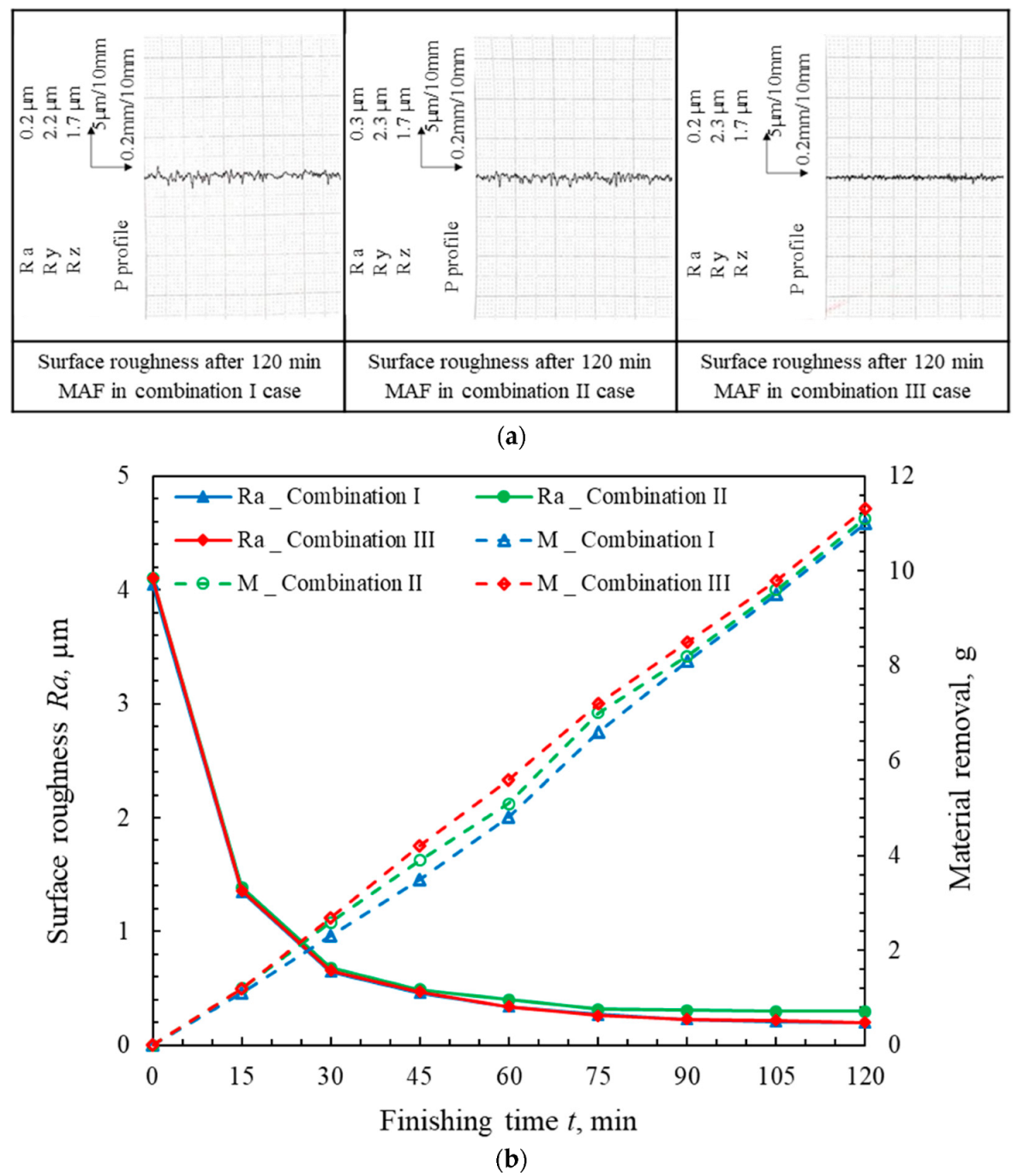
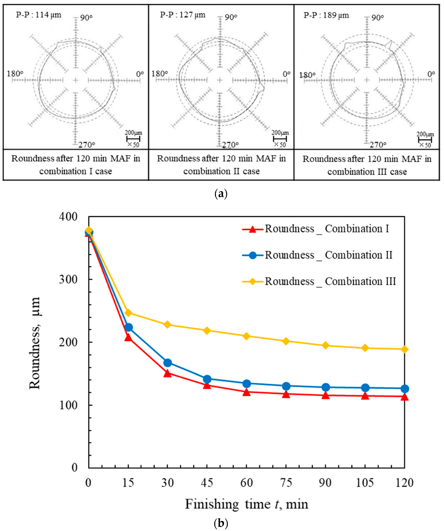
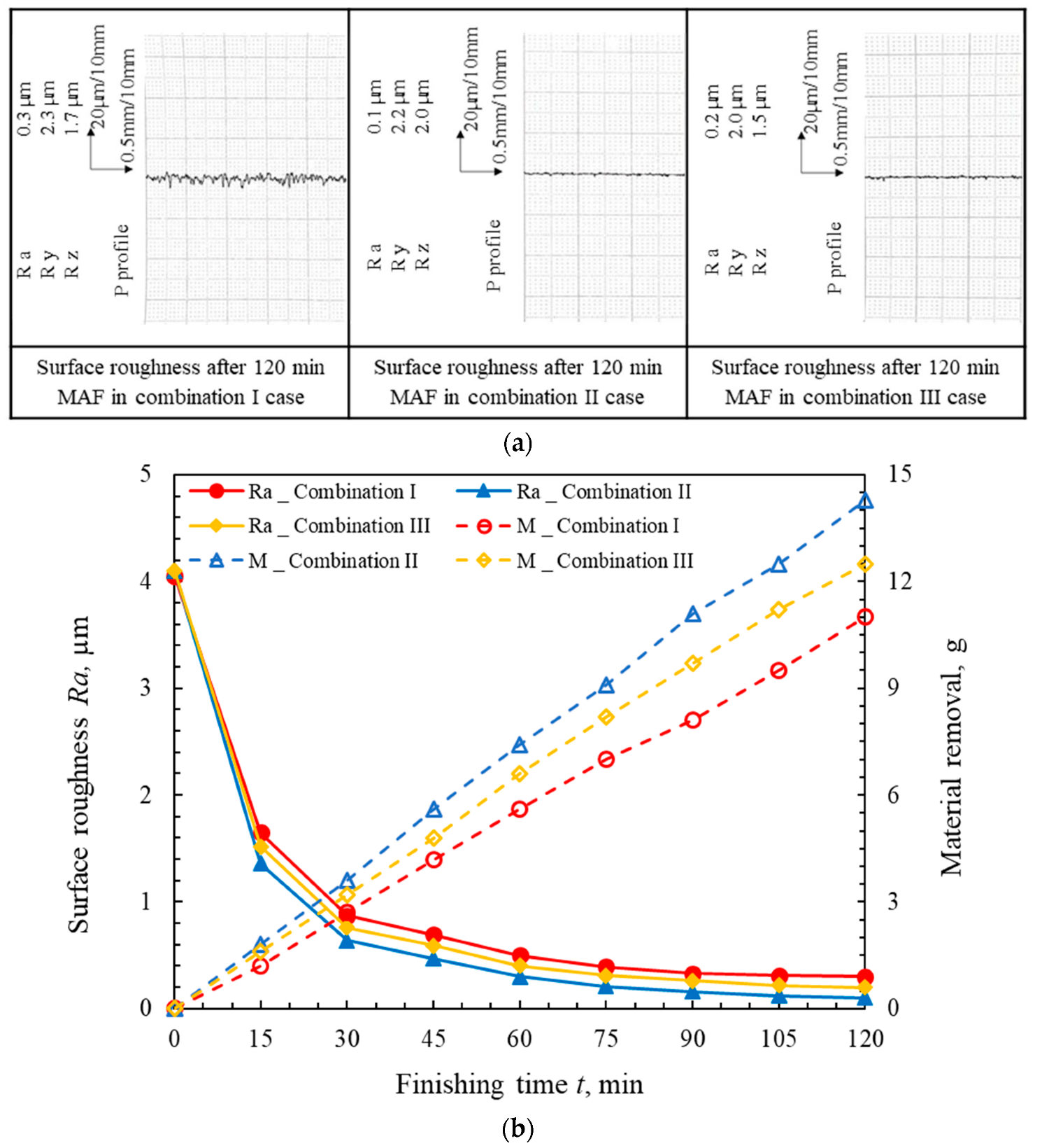
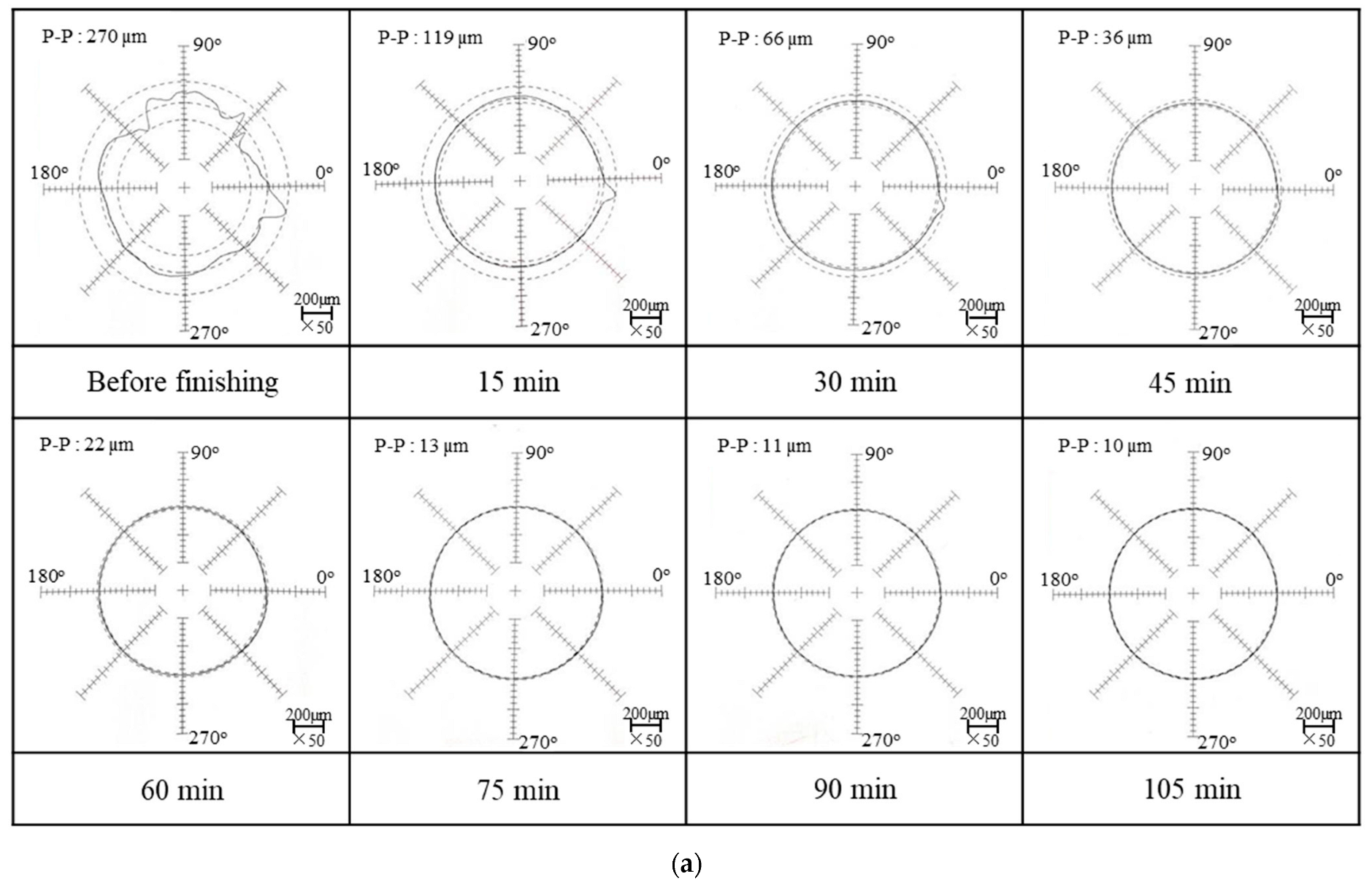
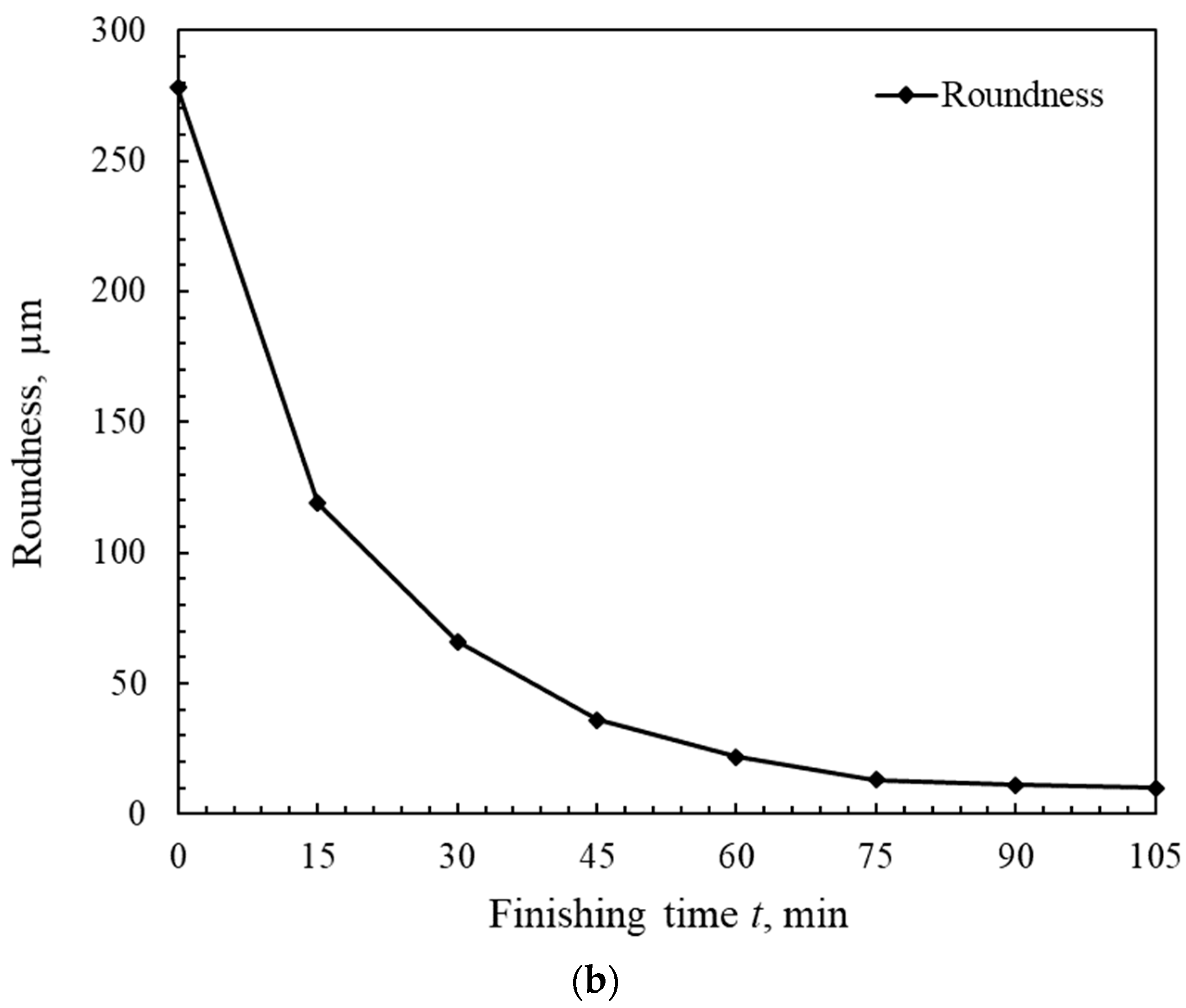
3.1. Effect of the Amount of Mixed Magnetic Abrasive on the Roundness and Surface Roughness

Figure 4 shows the change in roundness of the internal surface in the three different combinations of mixed magnetic abrasive after 120 min of the MAF process. After each finishing stage, the change in roundness of the internal surface was measured by a roundness meter, as shown in Figure 4b. From the experimental results, it can be confirmed that the change in roundness of the internal surface in the conditions of combinations I and II are similar and better than the roundness of the internal surface in the condition of combination III. Additionally, it was also found that the change in roundness of the internal surface was steady after 60 min of finishing. The profile morphologies of the roundness in different combinations after 120 min of the MAF process are shown in Figure 4a. The profile morphology of the internal surface in the condition of combination I was the best. Thus, the optimal combination of the mixed magnetic abrasive was considered as 20 g of 1680 µm electrolytic iron powder and 20 mL of 7.5 wt% #400WA slurry for the roundness of the internal surface. Since the ability of the magnetic field to adsorb mixed magnetic abrasive is limited, excessive mixed magnetic abrasive will cause the abrasive particles to squeeze each other, so that the finishing efficiency is reduced. Furthermore, the reason for the roundness being almost unchanged was that the #400WA abrasive and roundness reached a balance when the finishing time exceeded 60 min.
The change in surface roughness Ra and material removal M in the three different combinations of the mixed magnetic abrasive are shown in Figure 5. From the experimental results, as shown in Figure 5b, it can be observed that the surface roughness Ra in the conditions of combinations I and III are similar, and that they are better than the surface roughness Ra of the internal surface in the condition of combination II. The material removal increased with the increase in the amount of mixed magnetic abrasive. In addition, it was also found that the rate of change in surface roughness Ra of the internal surface was significantly slowed down after 60 min of finishing. The profile morphologies of the internal surface in different combinations after 120 min of the MAF process are shown in Figure 5a. The profile morphology of the internal surface in the condition of combination I was the best. Therefore, the optimal combination of the mixed magnetic abrasive was considered as 20 g of 1680 µm electrolytic iron powder and 20 mL of 7.5 wt% #400WA slurry for the surface roughness Ra. Since the size of the magnetic abrasive particles and the surface roughness reached a balance, the change in surface roughness Ra was not obvious after 60 min of finishing.

3.2. Effect of the Relative Rotation Speed of the Tube Workpiece and the External Magnetic Poles on the Roundness and Surface Roughness

The change in roundness of the internal surface in the three different combinations of workpiece and external pole revolutions after 120 min of the MAF process are described in Figure 6. From the experimental results, as shown in Figure 6b, it can be observed that the roundness in the condition of combination I is better than that in the other two combinations (II and III). The profile morphology of the roundness after 120 min of the MAF process is optimal in the condition of combination I, as can be observed in Figure 6a. This is because the auxiliary magnetic machining tool produces a high centrifugal force with a high-speed rotation of external poles. The best roundness for the internal surface can be obtained at a high rotation speed of the external poles.
Figure 7 shows the change in surface roughness Ra and material removal M in the three different combinations of the workpiece and external poles revolutions after 120 min of the MAF process. Figure 7b reveals that the surface roughness Ra in the condition of combination II is slightly better than that in the other two combinations (I and III). The greatest material removal M was also obtained in the condition of combination II. The optimal profile morphology of the internal surface was considered in the condition of combination II, as can be observed in Figure 7a. A large centrifugal force was generated with a high-speed rotation of external poles. On the other hand, a high polishing efficiency can be realized from the considerable speed difference between the rotations of the external poles and the workpiece. However, the extremely high speed of the external poles or very-high speed difference between the rotations of the external poles and the workpiece easily causes the internal poles to overturn in the tube. Hence, a better surface roughness of the internal surface was easily obtained in the condition of combination II.

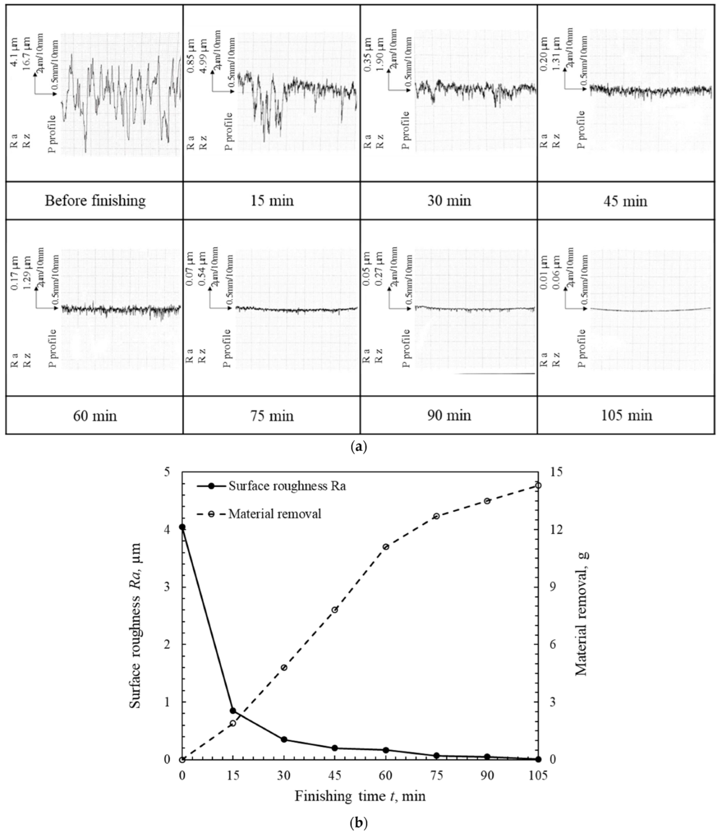
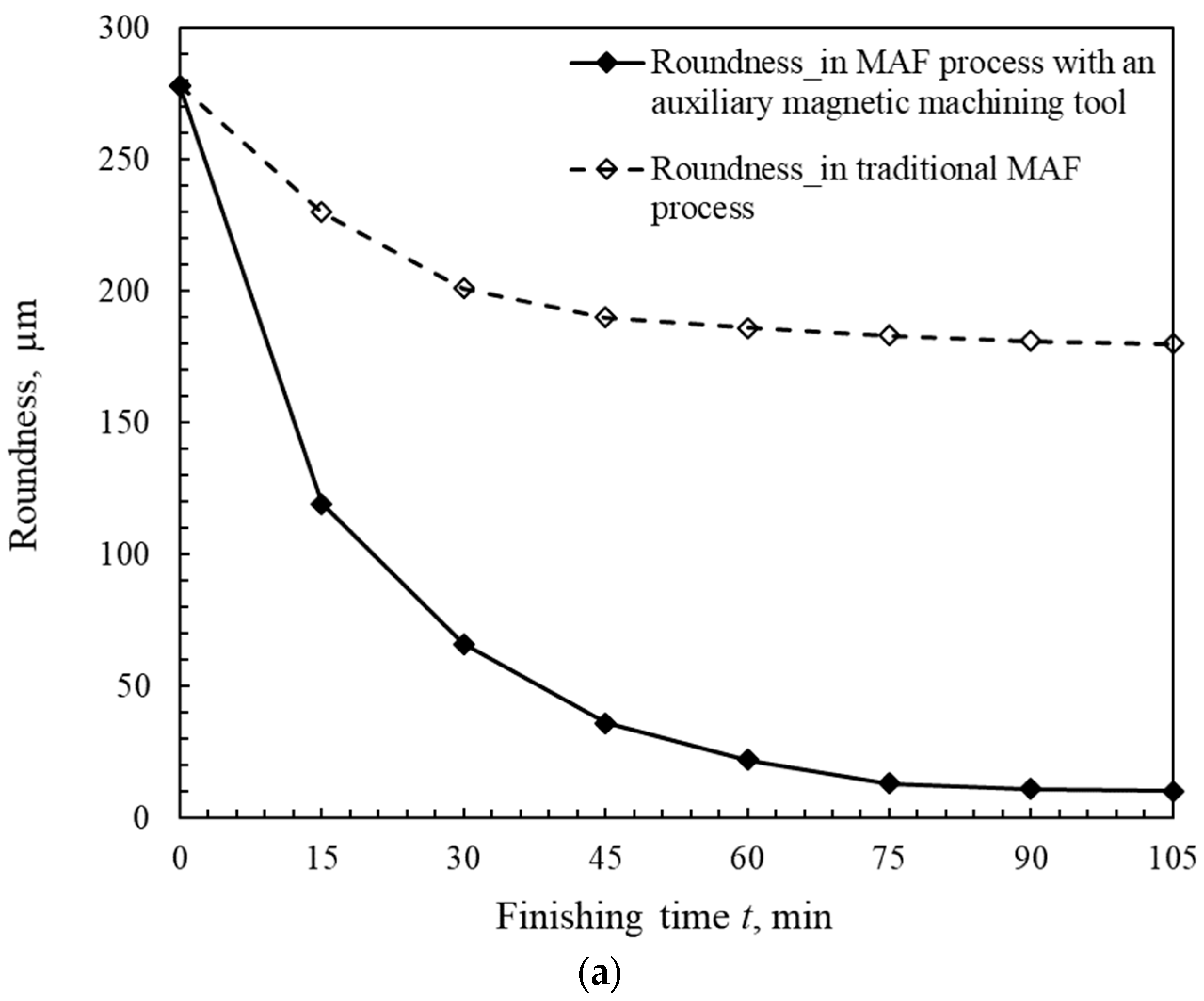
3.3. Multi-Stage MAF Processes in the Case of High-Speed Rotations

Based on the above-mentioned two experimental investigations, we performed this experiment in multiple stages in the case of a high-speed rotation. Compared with the previous experiments, the rotation speeds of the workpiece and external poles were, respectively, raised to 240 and 300 min−1. According to the degree of change in roundness and surface roughness Ra, we also adjusted the particles sizes of the mixed magnetic abrasive during the different finishing stages. The first three finishing stages were executed 2 times, and each finishing stage lasted 15 min. The last finishing stage was only executed once. The total finishing time was 105 min. Moreover, we chose a workpiece with a smaller weld seam to replace the previous workpiece.
Based on the influence of the size of the magnetic abrasive particles on the surface roughness, the multi-stage MAF process was performed by continuously adjusting the size of the magnetic abrasive particles. The profile morphologies and change in roundness of the internal surface after each finishing stage are respectively shown in Figure 8a,b. Compared with the above-mentioned two experimental results, it was found that the roundness of the internal surface was significantly improved at a high-speed rotation, and the roundness reached 66 µm after the first two finishing stages (30 min). This was because a larger centripetal force was generated in the case of the high-speed rotation. On the other hand, the roundness of the internal surface continued to be improved further by reducing the size of the abrasive particles from the third finishing stage (45 min). The roundness reached 22 µm by using 20 g of 330 µm electrolytic iron powder mixed with 20 mL of #1000WA slurry after the fourth finishing stage (60 min), and the roundness reached 11 µm by using 20 g of 75 µm electrolytic iron powder mixed with 20 mL of #4000WA slurry after the sixth finishing stage (90 min). Hence, it was considered that the used abrasive particle sizes matched the roundness in different finishing stages. Finally, the roundness reached 10 µm by using 20 g of 30 µm electrolytic iron powder mixed with 20 mL of 1~2 µm diamond particles after the last finishing stage (105 min). The change in the roundness almost reached the limit until the last finishing stages.
The change in surface roughness Ra and material removal M in the case of high-speed rotations after 105 min of the multi-stage MAF process are shown in Figure 9a,b. Compared with the above-mentioned two experimental results, it was regarded that the surface roughness of the internal surface Ra drastically declined to 0.35 µm at a high-speed rotation after the first two finishing stages. Subsequently, the surface roughness Ra continued to decrease to 0.17 µm when the size of the abrasive particles decreased after the fourth finishing stage. However, the change in surface roughness Ra was very limited when the size of the abrasive particles was reduced further. The surface roughness Ra can reach 10 nm by using 20 g of 75 µm electrolytic iron powder mixed with 20 mL of #4000WA slurry after the last finishing stages. On the other hand, the material removal M was significant in the first four finishing stages, and the material removal rate tended to decrease when the size of the abrasive particles decreased further during the last three finishing stages. Thus, the high-speed rotation and adjusting the size of the abrasive particles in a multi-stage process played a vital role in attaining both a better surface roughness and roundness.
The non-contact 3D morphology of the unfinished and finished internal surfaces are shown in Figure 10a. The original morphology with a lot of initial texture lines can be clearly observed on the internal surface of the tube workpiece before finishing. Compared with the original morphology of internal surface, it was recognized that the protruding part of the original internal surface was almost removed after the MAF process. Although the individual points remain higher or lower after the MAF process, the morphology of the finished internal surface can be considered as uniform. Furthermore, from the physical photos of the internal surface before and after 105 min of finishing, as shown in Figure 10b, it was confirmed that not only can the weld bead be removed, but mirror-finishing can also be achieved by using the MAF process.

4. Discussion

During the MAF process, it was assumed that the internal surface profile of the workpiece was uniform and the initial surface roughness was assumed to be Ra0. The mixed magnetic abrasive reciprocated motion along the axis of the workpiece under the action of the magnetic field force. The ratio of the peak-to-valley roughness Ra0 and the arithmetic average roughness Ra in the scratch direction were constant. Assumed Rai was the surface roughness of the internal surface, which was obtained after the i-th finishing. According to the parameter of the mixed magnetic abrasive used during each finishing stage, the calculation model of the change in surface roughness is described by Formula (1):
R a i = R a i 1 1 7 N l s R c 2 R w 2 [ d g 2 4 sin 1 2 t ( d g t ) d g t ( d g t ) ( d g 2 t ) ]  
In Formula (1), “N” is the number of abrasive particles that act on the unit area, “ls” is the finishing length, “Rw” is the radius of the mixed magnetic abrasive slurry, “RC” is the inner diameter of the tube workpiece, “dg” is the diameter of the abrasive particle, and “t” is the depth of material removal. From Formula (1), it can be observed that the material removal depth should be greater when the inner surface of the tube workpiece is rough. Moreover, the diameter of the abrasive particle should correspond to the current surface roughness. In order to obtain a high-precision inner surface, it is necessary to adjust the size of the abrasive particle diameter in time with the change in the surface roughness of the workpiece.
In the MAF process, the finishing force in X, Y, Z directions and synthetic forces can be calculated by Formulas (2)–(5).
F x = K D 3 χ μ 0 H ( H / x )
F y = K D 3 χ μ 0 ( H / y )
F z = K D 3 χ μ 0 H ( H / z )
F2 = Fx2 + Fy2 + Fz2
where “K” is the correction coefficient, “D” is the diameter of the magnetic abrasive particle, “χ” is the susceptibility of the magnetic abrasive particle, “μ0” is the permeability of space, “H” is the intensity of the magnetic field, and H / x and H / y are, respectively, the gradients of the magnetic field intensity in the x and y directions. From Formulas (2)–(5), it is considered that the intensity of magnetic field “H” is the main factor that affects the finishing force. The intensity of magnetic field “H” can be calculated by Equation (6):
H = B/µ
where “B” is the magnetic flux density and “µ” is the magnetic permeability of the medium. The intensity of magnetic field “H” is proportional to magnetic flux density “B”. The nephogram graph of the magnetic flux density and the distribution map of magnetic field lines in the traditional MAF process and the MAF process with an auxiliary magnetic machining tool were analyzed by Ansys Maxwell software and shown in Figure 11 and Figure 12. The maximum element size of the mesh was set to 0.5 mm. The magnetic flux density (approximately 0.54 T) near the internal surface of the tube wall in the MAF process with an auxiliary magnetic machining tool was greater than that (approximately 0.16 T) in the traditional MAF process. Additionally, a relatively strong magnetic flux density was generated on the end face of the magnetic pole perpendicular to the direction of the workpiece. From Figure 12, it can be observed that the aggregation effect of the magnetic force lines is obvious near the internal surface of the tube wall when using an auxiliary magnetic machining tool inside the tube workpiece. From the comparison, it was regarded that the magnetic machining force in the MAF process with an auxiliary magnetic machining tool was greater than that in the traditional MAF process. Hence, this new finishing process method can be proven to finish, more efficiently, the internal surface of the thick-walled tube.
Finally, the comparisons of roundness and surface roughness in the traditional MAF process and MAF process with an auxiliary magnetic machining tool are shown in Figure 13. It can be observed that the roundness of the internal surface following the MAF process with an auxiliary magnetic machining tool is better than that after the traditional MAF process, as shown in Figure 13a. In addition, it can also be observed that the surface roughness Ra following the MAF process with an auxiliary magnetic machining tool is less than that following the traditional MAF process; the material removal in the MAF process with an auxiliary magnetic machining tool is 2.4 times greater than that in the traditional MAF process, as can be observed in Figure 13b.

5. Conclusions

This paper proposed a novel MAF process that is magnetic abrasive finishing with an auxiliary magnetic machining tool for the internal surface finishing of a thick-walled tube. The effect of some of the main finishing parameters on the finishing characteristics was investigated in this study. The main conclusions are summarized as follows:
  • The proposed method of magnetic abrasive finishing with an auxiliary magnetic machining tool successfully achieved the internal surface finishing of the thick-walled tube. Additionally, the auxiliary magnetic machining tool was designed and applied in the experiments of the MAF process to improve the strength of magnetic field force.
  • A better internal surface quality was easily obtained in the case of a high-speed rotation. Since the auxiliary magnetic machining tool produced a large centripetal force with a high-speed rotation in a closed magnetic field circuit, the roundness and surface roughness could be improved.
  • On the other hand, the size of the abrasive particles should match the surface quality workpiece. Hence, the final experiment was performed by adjusting the size of the abrasive particles in a multi-stage process to obtain better internal surface quality.
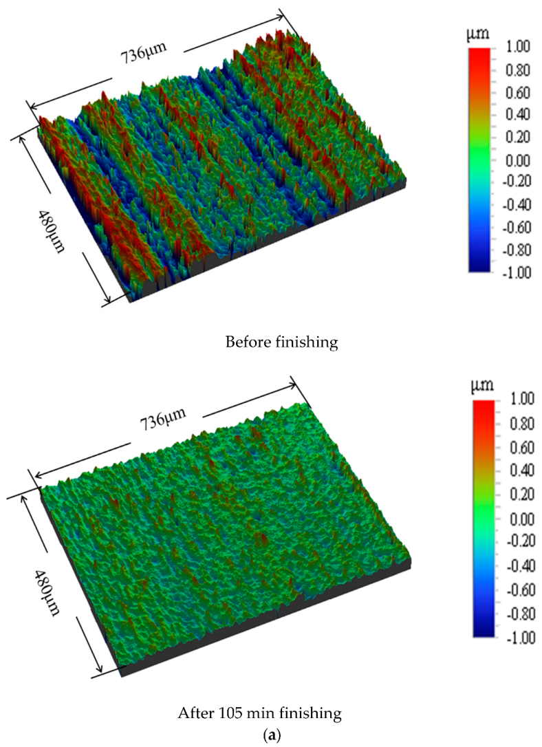
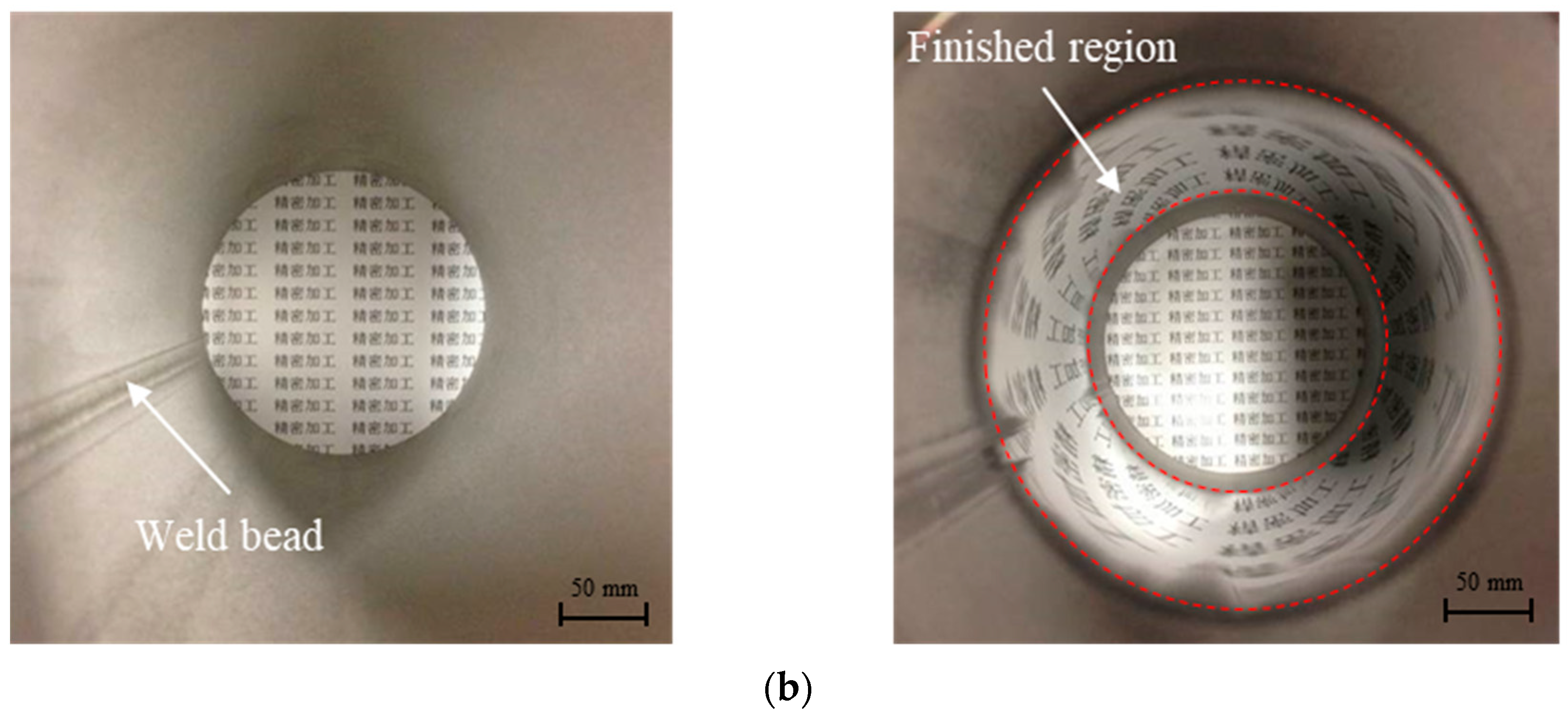
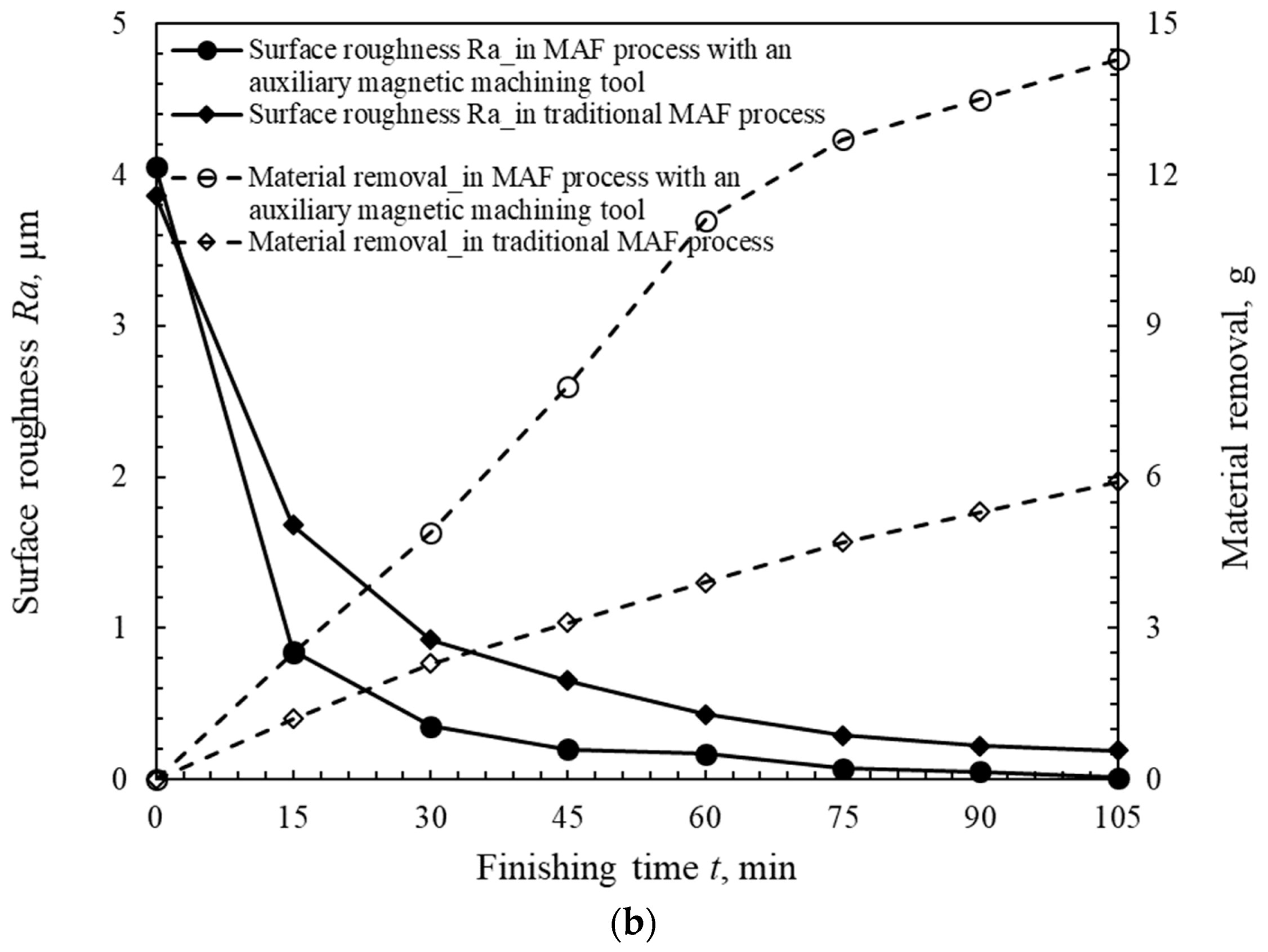
  • Compared with the traditional MAF process, the roundness and the surface roughness were improved by using an auxiliary magnetic machining tool. Furthermore, the roundness reached 10 µm from an original roundness value of 270 µm, and the surface roughness reached 10 nm from an original roughness value of 4.1 µm in a multi-stage process in the case of high-speed rotation after 105 min of the MAF process.
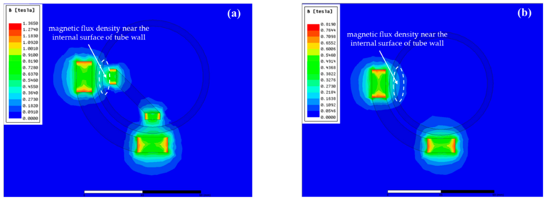
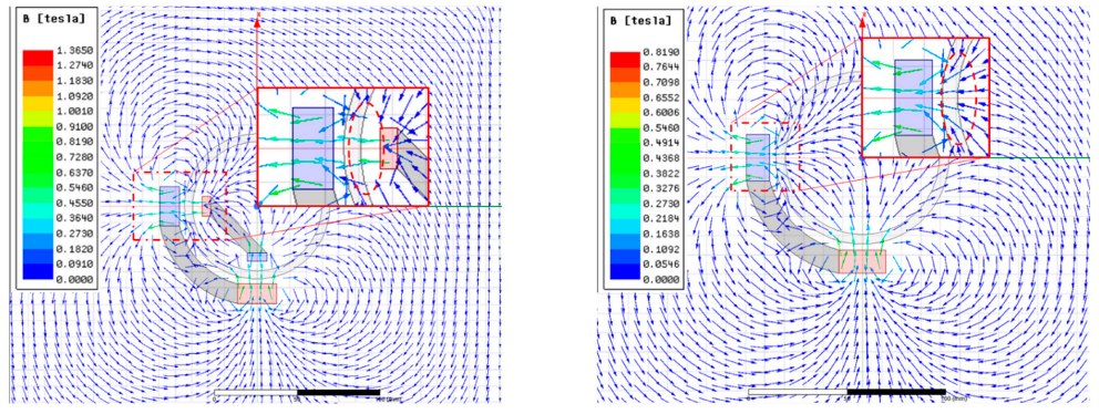
  • The nephogram graph of the magnetic flux density and the distribution map of the magnetic field lines in the traditional MAF process and MAF process with an auxiliary magnetic machining tool were analyzed by Ansys Maxwell software. The comparison results reveal that a greater magnetic flux density and a better aggregation effect of the magnetic force lines are generated in a closed magnetic field circuit.

Author Contributions

The first author, Y.Y., is responsible for writing this paper and analyzing the magnetic field of the magnetic machining tools. The corresponding author, X.S., his responsible for proposing the method, planning the experiments, and developing the experiments. Y.X. is responsible for collecting and processing the data. B.L. and Y.F. are responsible for performing the experiments. R.C. and Y.J. are responsible designing the magnetic machining tools and analyzing the magnetic field of the magnetic machining tools. W.H. statistically analyzed and measured the works. All authors have read and agreed to the published version of the manuscript.

Funding

We declare the valuable contributions to and support for this study from Dr. Start Funding from Longyan University (LB2019002 and LB2020005), the Huaqiao University Engineering Research Center of Brittle Materials Machining (MOE, 2020IME-003), Young Teachers’ Education Research Project of Fujian (JAT210448), Fundamental Research Funds for the Provincial Universities of Zhejiang (RF-A2020003) and Natural Science Foundation of Fujian Province (Pending).

Institutional Review Board Statement

Not applicable.

Informed Consent Statement

Not applicable.

Data Availability Statement

Not applicable.

Acknowledgments

This work was supported by Yunlong Jiang from the Utsunomiya University Creative Department for Innovation (CDI).

Conflicts of Interest

The authors declare no conflict of interest.

References

  1. Fisher, J.; Kaufmann, E.; Pense, A. Effect of Corrosion on Crack Development and Fatigue Life. Transp. Res. Rec. 1998, 1624, 110–117. [Google Scholar] [CrossRef]
  2. Kumar, C.G.; Anand, S.K. Significance of microbial biofilms in food industry: A review. Int. J. Food Microbiol. 1998, 42, 9–27. [Google Scholar] [CrossRef]
  3. Hang, W.; Wei, L.Q.; Debela, T.T.; Chen, H.Y.; Zhou, L.B.; Yuan, J.L.; Ma, Y. Crystallographic orientation effect on the polishing behavior of LiTaO3 single crystal and its correlation with strain rate sensitivity. Ceram. Int. 2022, 48, 7766–7777. [Google Scholar] [CrossRef]
  4. Shinmura, T.; Takazawa, K.; Hatano, E.; Matsunaga, M. Study on magnetic abrasive finishing. Ann. CIRP 1990, 39, 325–328. [Google Scholar] [CrossRef]
  5. Sun, X.; Zou, Y.H. Development of magnetic abrasive finishing combined with electrolytic process for finishing SUS304 stainless steel plane. Int. J. Adv. Manuf. Technol. 2017, 92, 3373–3384. [Google Scholar] [CrossRef]
  6. Liu, J.N.; Zou, Y.H. Study on Mechanism of Roundness Improvement by the Internal Magnetic Abrasive Finishing Process Using Magnetic Machining Tool. Machines 2022, 9, 112. [Google Scholar] [CrossRef]
  7. Deng, Y.M.; Zhao, Y.G.; Zhao, G.Y.; Gao, Y.W.; Liu, G.X.; Wang, K. Study on magnetic abrasive finishing of the inner surface of Ni–Ti alloy cardiovascular stents tube. Int. J. Adv. Manuf. Technol. 2021, 118, 2299–2309. [Google Scholar] [CrossRef]
  8. Shinmura, T.; Takazawa, K.; Hatano, E. Study on magnetic abrasive finishing: Rounding condition and its confirmation by experiment. Bull. Jpn. Soc. Precis. Eng. 1986, 52, 1598–1603. (In Japanese) [Google Scholar] [CrossRef]
  9. Yamaguchi, H.; Shinmura, T.; Sekine, M. Uniform Internal Finishing of SUS304 Stainless Steel Bent Tube Using a Magnetic Abrasive Finishing Process. J. Manuf. Sci. Eng. 2005, 127, 605–611. [Google Scholar] [CrossRef]
  10. Wang, Y.; Hu, D. Study on the inner surface finishing of tubing by magnetic abrasive finishing. Int. J. Mach. Tools Manuf. 2005, 45, 43–49. [Google Scholar] [CrossRef]
  11. Yamaguchi, H.; Shinmura, T. Study on a new internal finishing process by the application of magnetic abrasive machining: Discussion of the roundness. Bull. Jpn. Soc. Precis. Eng. 1996, 62, 1617–1621. (In Japanese) [Google Scholar] [CrossRef]
  12. Shinmura, T.; Aizawa, T. Study on Internal Finishing of a Non-ferromagnetic Tubing by Magnetic Abrasive Machining Process. Bull. Jpn. Soc. Precis. Eng. 1989, 23, 37–41. (In Japanese) [Google Scholar]
  13. Shinmura, T.; Yamaguchi, H. Study on a New Internal Finishing Process by the Application of Magnetic Abrasive Machining: Internal Finishing of Stainless Steel Tube and Clean Gas Bomb. JSME Int. J. C-Mech. Sy. 1995, 38, 798–804. [Google Scholar] [CrossRef]
  14. Zhang, S.R.; Yang, L.F.; Wu, G.X. Experimental Study on Increasing Magnetic Abrasive Finishing Efficiency of Finishing Nonferromagnetic Materials. Key Eng. Mater. 2007, 359, 300–304. [Google Scholar] [CrossRef]
  15. Yamaguchi, H.; Shinmura, T.; Ikeda, R. Study of Internal Finishing of Austenitic Stainless Steel Capillary Tubes by Magnetic Abrasive Finishing. J. Manuf. Sci. Eng. 2007, 129, 885–892. [Google Scholar] [CrossRef]
  16. Hitomi, Y.; Anil, K.S.; Michael, T.; Fukuo, H. Magnetic Abrasive Finishing of cutting tools for high-speed machining of titanium alloys. CIRP J. Manuf. Sci. Technol. 2014, 7, 299–304. [Google Scholar]
  17. Muhamad, M.R.; Zou, Y.H.; Sugiyama, H.S. Development of a new internal finishing of tube by magnetic abrasive finishing process combined with electrochemical machining. Int. J. Mech. Eng. Appl. 2015, 3, 22–29. [Google Scholar]
  18. Muhamad, M.R.; Zou, Y.H.; Sugiyama, H.S. Investigation of the finishing characteristics in an internal tube finishing process by magnetic abrasive finishing combined with electrolysis. Trans. IMF 2016, 94, 159–165. [Google Scholar] [CrossRef]
  19. Muhamad, M.R.; Jamaludin, M.F.; Ab Karim, M.S.; Yusof, F.; Zou, Y.H. Effects of electrolysis on magnetic abrasive finishing of AA6063-T1 tube internal surface using combination machining tool. Materialwiss. Werkst. 2018, 49, 442–452. [Google Scholar] [CrossRef]
  20. Wang, C.; Loh, Y.M.; Cheung, C.F.; Wang, S.; Ho, L.T.; Li, Z. Shape-adaptive magnetic field-assisted batch polishing of three-dimensional surfaces. Precis. Eng. 2022, 76, 261–283. [Google Scholar] [CrossRef]
  21. Wang, T.; Huang, L.; Kang, H.; Choi, H.; Kim, D.W.; Tayabaly, K.; Idir, M. RIFTA: A Robust Iterative Fourier Transform-based dwell time Algorithm for ultra-precision ion beam figuring of synchrotron mirrors. Sci. Rep. 2020, 10, 8135. [Google Scholar] [CrossRef] [PubMed]
  22. Wang, C.J.; Cheung, C.F.; Ho, L.T.; Liu, M.Y.; Lee, W.B. A novel multi-jet polishing process and tool for high-efficiency polishing. Int. J. Mach. Tools Manuf. 2017, 115, 60–73. [Google Scholar] [CrossRef]
  23. Beaucamp, A.; Namba, Y. Super-smooth finishing of diamond turned hard X-ray molding dies by combined fluid jet and bonnet polishing. CIRP Ann. 2013, 62, 315–318. [Google Scholar] [CrossRef]
Figure 1. (a) Machining principle of traditional magnetic abrasive finishing process for the thin-walled tube workpiece; (b) machining principle of magnetic abrasive finishing process with an auxiliary magnetic machining tool for the tube workpiece.
Machines 10 00529 g001
Figure 2. Three-dimensional model and external view of experimental setup. (a) Three-dimensional model of experimental setup; (b) physical photo of experimental setup.
Machines 10 00529 g002
Figure 3. Design and external view of auxiliary magnetic machining tool.
Machines 10 00529 g003
Figure 4. Change in roundness of internal surface in different combinations of mixed magnetic abrasive after 120 min of the MAF process. (a) Profile morphologies of the roundness after 120 min of MAF process; (b) change in roundness of internal surface after each finishing stage.
Machines 10 00529 g004
Figure 5. Change in surface roughness Ra and material removal M in different combinations of mixed magnetic abrasive after 120 min of MAF process. (a) Profile morphologies of the internal surface roughness after 120 min of MAF process; (b) change in surface roughness Ra and material removal M after each finishing stage.
Machines 10 00529 g005
Figure 6. Change in roundness of internal surface in different combinations of workpiece and external pole revolutions after 120 min of MAF process. (a) Profile morphologies of the roundness after 120 min of MAF process; (b) change in roundness of internal surface after each finishing stage.
Machines 10 00529 g006
Figure 7. Change in surface roughness Ra and material removal M in different combinations of workpiece and external pole revolutions after 120 min of MAF process. (a) Profile morphologies of the internal surface roughness after 120 min of MAF process; (b) change in surface roughness Ra and material removal M after each finishing stage.
Machines 10 00529 g007
Figure 8. Change in roundness of internal surface in a multi-stage process in the case of high-speed rotation after 105 min of MAF process. (a) Profile morphologies of the roundness after each finishing stage; (b) change in roundness of internal surface after each finishing stage.
Machines 10 00529 g008aMachines 10 00529 g008b
Figure 9. Change in surface roughness Ra and material removal M in a multi-stage process in the case of high-speed rotation after 105 min of MAF process. (a) Profile morphologies of the internal surface roughness after 105 min of MAF process; (b) change in surface roughness Ra and material removal M after each finishing stage.
Machines 10 00529 g009
Figure 10. Comparison of the internal surface before and after finishing. (a) Non-contact 3D morphology of unfinished and finished internal surfaces; (b) physical photos of the internal surface before and after finishing (“精密加工” means “Precision Machining”).
Machines 10 00529 g010aMachines 10 00529 g010b
Figure 11. Nephogram graph of magnetic flux density for the traditional MAF and MAF with additional magnetic tool. (a) Nephogram graph of the magnetic flux density for MAF with additional magnetic tool; (b) Nephogram graph of magnetic flux density for the traditional MAF.
Machines 10 00529 g011
Figure 12. Distribution map of magnetic field lines for the traditional MAF and MAF with additional magnetic tool. (Left) Distribution map of magnetic field lines for MAF with additional magnetic tool; (Right) Distribution map of magnetic field lines for the traditional MAF.
Machines 10 00529 g012
Figure 13. Comparison of the finishing surface quality in two different finishing methods. (a) Change in roundness of internal surface in two different finishing methods; (b) change in surface roughness Ra and material removal M in two different finishing methods.
Machines 10 00529 g013aMachines 10 00529 g013b
Table 1. Experimental conditions of experiment I.
WorkpieceSUS304 stainless-steel welded tube ∅89 × ∅79.1 × 200 mm
Auxiliary magnetic machining toolMagnetic material: Nd-Fe-B; type: NdFeB380/80
Yoke: SS400 steel
Molding material: polymer
Working gapBetween the internal and external magnets: 9 mm
Between the internal magnets and internal surface of workpiece: 1 mm
Between the external magnets and external surface of workpiece: 3 mm
Rotation speed of workpiece180 min−1
Rotation speed of external poles131 min−1
Feeding speed of external poles1280 mm/min
Finishing length90 mm
Combinations of mixed magnetic abrasive Combination I: 20 g (1680 µm electrolytic iron powder) and 20 mL (7.5 wt% #400WA slurry)
Combination II: 30 g (1680 µm electrolytic iron powder) and 20 mL (7.5 wt% #400WA slurry)
Combination III: 30 g (1680 µm electrolytic iron powder) and 30 mL (7.5 wt% #400WA slurry)
Finishing time8 × 15 min
Table 2. Experimental conditions of experiment II.
WorkpieceSUS304 stainless-steel welded tube ∅89 × ∅79.1 × 200 mm
Magnetic particlesElectrolytic icon particles, 1680 µm, 20 g
Abrasives slurry#400WA slurry 7.5 wt%, 20 mL
Combinations of workpiece and external pole revolutionsCombination I: 180 min−1 (workpiece) and 132 min−1 (external pole)
Combination II: 129 min−1 (workpiece) and 181 min−1 (external pole)
Combination III: 82 min−1 (workpiece) and 229 min−1 (external pole)
Table 3. Experimental conditions of experimental III.
WorkpieceSUS304 stainless-steel welded tube ∅90 × ∅80 × 200 mm
Rotation speed of workpiece240 min−1
Rotation speed of external poles300 min−1
Combination of mixed magnetic abrasive in different finishing stagesStage I: 30 g (1680 µm electrolytic iron powder) and 20 mL (#400WA slurry)
Stage II: 20 g (330 µm electrolytic iron powder) and 20 mL (#1000WA slurry)
Stage III: 20 g (75 µm electrolytic iron powder) and 20 mL (#4000WA slurry)
Stage Ⅳ: 20 g (30 µm electrolytic iron powder) and 20 mL (1~2 µm diamond particles)
Finishing timeStage I: 2 × 15 min
Stage II: 2 × 15 min
Stage III: 2 × 15 min
Stage Ⅳ: 1 × 15 min
Publisher’s Note: MDPI stays neutral with regard to jurisdictional claims in published maps and institutional affiliations.

