Article

Design, Manufacture, and Performance Testing of Extrusion–Pultrusion Machine for Fiber-Reinforced Thermoplastic Pellet Production

by
Cahyo Budiyantoro
1,2,
Heru S. B. Rochardjo
1,* and
Gesang Nugroho
1
1
Department of Mechanical and Industrial Engineering, Universitas Gadjah Mada, Yogyakarta 55281, Indonesia
2
Department of Mechanical Engineering, Universitas Muhammadiyah Yogyakarta, Yogyakarta 55183, Indonesia
*
Author to whom correspondence should be addressed.
Submission received: 29 December 2020 / Revised: 3 February 2021 / Accepted: 5 February 2021 / Published: 17 February 2021
(This article belongs to the Section Machine Design and Theory)

Abstract

:
This study aimed to develop an extrusion and pultrusion system for producing carbon fiber-filled thermoplastic pellets. The extruder delivers a plastic melt to an impregnation die in sufficient volume and is pulled out along with the fibers. The fibers pass in a sideways stretched condition through spreader pins attached in the melt pool, which can then be wetted optimally. The wetting effect was also improved by immersing fiber in a coupling agent solution at an elevated temperature before feeding to the extruder die. For machine performance testing, polypropylene was used as a matrix resin with the following parameters: a screw speed of 5 rpm, a die temperature of 210 °C, and a pulling speed of 56 mm/s. The pull-out test was conducted to assess the interfacial shear strength (IFSS) between fibers and matrix. Scanning electron microscopy (SEM) was applied to characterize the quality of fiber impregnation. SEM characterized a good bonding performance between carbon fiber and the matrix. The average IFSS of the results indicated a good resistance of fiber–matrix bonding against a pulling force. It proved that the combination of the extrusion–pultrusion system can produce high-quality filaments as a raw material of composite pellets.

1. Introduction

The manufacturing of thermoplastic-based composite components must consider several things, including selecting raw material, product design concepts, and fabrication techniques. There are two existing methods used to prepare the raw material for carbon fiber reinforced plastics (CFRPs): fiber-reinforced plastic granules and direct fiber-reinforced thermoplastic [1]. In the first method, semi-finished fibrous granules are fabricated first and then processed by injection molding or compression molding. In the second method, fibers, resins, and related additives are compounded in the extruder, and the compounded material is shaped into a final product by injection or compression molding. With those methods, fibers are usually chopped and mixed with the polymer matrix in either thermokinetic mixers or mixing chambers to blend them before entering in twin-screw extruders, and these methods are considered not adequate for an industrial scale [2,3]. The polymer pellets and chopped fibers are fed and transported into the screw, compressed by the feeding forces, and shaped by a solid plug, which thoroughly fills the screw channel [4]. The feeding is governed by the plastic’s relative friction against the screw and the barrel wall, which pushes the plug to the next zone. Fibers and resins do not coalesce in pellets when fed to the hopper, therefore there is no guarantee that all the fiber can continuously move along the molten plastic; thus, the fiber content’s consistency in the pellet cannot be ensured. Furthermore, in the stage of fiber-filled plastic pellet production, the bonding quality between fiber and matrix is usually not a significant concern. However, increasing the bonding quality of fiber and matrix bonding in pellets will reduce production cycle times at a later stage.
To maintain the fiber content’s stability in composite pellets, continuous fiber feeding is required in the pellet manufacturing method. Continuous fiber feeding is commonly applied in the pultrusion process, where the fiber content in the composite and the product’s dimension can be maintained stable; this method is most widely used in the composite pellet manufacturing industry. In this method, the reinforcing fibers are stretched unidirectionally across the resin bath and impregnated. The fiber that has been wetted by resin will then pass through the die, which is heated at the resin curing temperature. This process more often uses thermoset-based resins such as polyester, polyurethane, vinyl ester, and epoxy. There are several problems with the application of pultrusion to thermoplastic materials. Thermoplastic materials are limited to low-viscosity resins due to fiber wet-out requirements. Thermoplastic resins have a remarkably higher viscosity (ηTP = 200–5000 Pa s) than thermoset resins (ηTS = 0.2–10 Pa s), so the potential problems with thermoplastic impregnation are higher [5]. A uniform wetting of the single fibers is an essential issue [6]; therefore, an impregnation system should be introduced in the production of thermoplastic pellets. There are several methods for thermoplastic impregnation: powder impregnation, laminating, solvent impregnation, and melt impregnation. Melt impregnation is the most economical method to cover every fiber with penetrating plastic melt through fiber bundles. With this method, no extra investments for solvent removal and recycling are needed, and it can be used for any type of thermoplastic matrix [7]. The wetting of fiber can be fulfilled mechanically by the die design and fiber’s moving mechanism in the plastic melt [8]. During the impregnation stage, the fiber bundle must be in a wide-spread condition so that each strand of fiber is aligned and not overlapping and can be wet evenly by the matrix. Fiber spreading can be done by adding some spreading pins to the die design, where the fiber bundle will spread as it passes through the pin. The pin cross-curve radius and the height difference between pins affect the stretched fibers that pass through it [9]. Fiber spreading can overcome impregnation problems in high-viscosity thermoplastic. Another problem with the thermoplastic pultrusion is that the thermoplastic material has a limited residence time to be kept under melt conditions. If the residence time is exceeded, there will be degradation of the resin. The plastic melt in the resin bath must always be changed and come out along with the product to minimize the residence time. In the case of pultrusion, it is common to use a large volume of resin bath to accommodate a significant amount of resin melt. To control the volume of plastic melt that enters the resin bath, it requires a mechanism of rotating the screw to force the melt out of the die, like the extrusion process’s mechanism.
In a composite system, thermoplastic commonly has low surface energy and bonding adhesion [10]. A treatment on the fiber surface is needed to improve the surface energy, surface roughness, or chemical surface change so that the bonding strength and durability of composite adhesive bonding can be improved. The methods that can be used in fiber surface treatment, including wet oxidizing, whiskerization, sizing, thermal treatment, and applying coupling agent (CA). Those methods aim to improve the number of reactive groups or increase the fiber’s surface roughness to enhance the bonding quality with the matrix. Fiber treatment using a CA is a standard method among the other [11]. Silane CA forms an alkoxysilane group that can be reacted with the hydroxyl group after hydrolysis. Han et al. [12] proved that the interfacial strength between the polypropylene matrix and carbon fiber could be increased by applying a combination of silane coupling agent and plasma treatment. The hydroxyl group on the carbon fibers induced by plasma treatment reacted with the silane CA, reinforcing the polypropylene and the carbon fiber interface through an interpenetrating polymer network. Shi et al. [13] investigated the effect of carbon fiber surface treatment on composite mechanical properties; nitric acid treatment on carbon fibers increased the composites’ mechanical properties. Moreover, the improvement was achieved when the silane CA was applied to carbon fiber. It proved that the interfacial strength of the composite was enhanced by applying the coupling agent.
Several studies related to fiber composite filament manufacturing have been conducted, some of which can be used to manufacture composite pellets. Marissen et al. [14] designed melt impregnation technology that can be integrated with the extrusion process in fiber-reinforced composites. The fiber bundle passed through five conical spreading pins in the polypropylene matrix. This method can improve impregnation quality; however, this technology is complex enough to be applied in mass production and retains the plastic melt in a container. Marissen only considers impregnation without observing other quality indicators, such as fiber–matrix bonding. Zolfaghari et al. [15] developed an extrusion method to manufacture continuous glass fiber-reinforced wood plastic composite. This method is equipped with a fiber feeder, spreader pins, and an impregnation die. However, in this method, the spreader pins are placed outside the matrix melting system. The fibers return to form fiber bundles when they are pulled into the impregnation die, so there is not enough contact with the matrix. Fiber treatment is also not carried out in order to improve impregnation quality. Wang et al. [16] have established an extrusion–calendering method to manufacture unidirectional continuous fiber-reinforced polypropylene single-polymer composites. The type of fiber used is continuous PP fiber so that it does not cause problems in terms of impregnation. To cover the fibers with a matrix, a two-stage calendering process is required.
In this study, an extrusion–pultrusion machine was developed to produce a carbon fiber-filled thermoplastic composite filament. The machine was designed and manufactured to accommodate an integration function of extrusion and pultrusion. The fiber was subjected to coupling agent treatment at elevated temperature to increase their surface roughness before feeding them into extruder die. The impregnation die had a melt pool, and the fiber passed through spreader pins attached to this melt pool. The filament was targeted to have uniformity in shape and dimensions, high volume fraction, and high impregnation quality. Furthermore, the filaments can be cut into pellets and used to manufacture complex products through the molding process. However, this study aimed to prove the design concept and ensure the machine’s performance in producing filaments as the base material for composite pellets. In this stage, a feasibility study was carried experimentally. Further research is needed to investigate the effect of different process parameters on the quality of the composite filament.

2. Design Considerations

2.1. Pellet Material

The composite pellet product was targeted to have a diameter of 2 mm with the fiber fully covered and wetted uniformly by the matrix. For the machine performance testing, a high impact polypropylene copolymer Cosmoplene AW564 made under license by Sumitomo Chemical Co. Japan was used as a matrix material. This material was medium flow, high impact, and high stiffness copolymer grade [17]. Carbon fiber T700SC 12K [18], made by Toray, Tokyo, Japan, was used as continuous reinforcement. γ-aminopropyltriethoxy Silane (APTS) was chosen as a coupling agent supplied by Hangzhou Jessica Chemicals Co., Ltd. It is commonly used in composite materials to improve the compatibility between the matrix resin and inorganic substance, significantly improving the flexure strength, tensile strength, and other properties of composite materials [19]. The properties of the incorporated material are shown in Table 1.

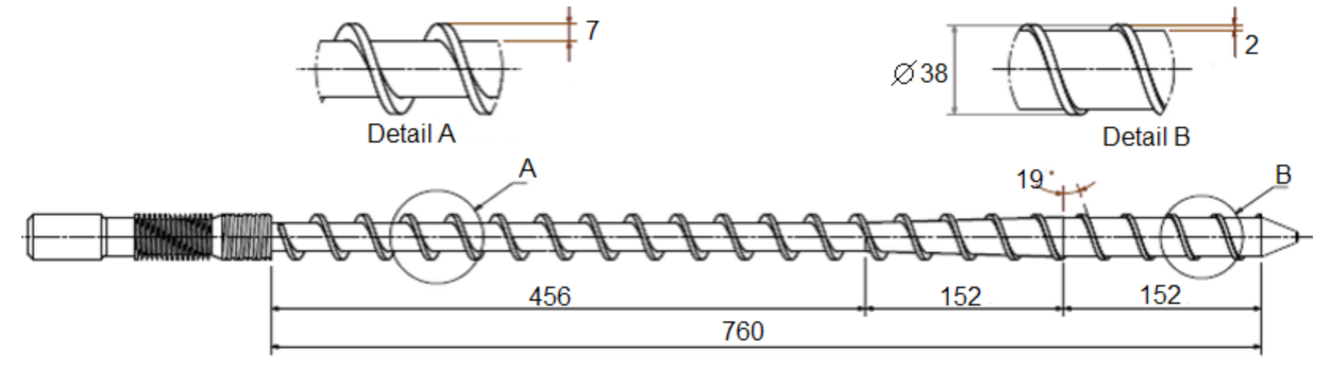
2.2. Design Features of Extrusion Unit

The machine was divided into two units to represent two functions, namely, extrusion, and pultrusion. The extrusion unit was designed with a simple type of screw—a single screw extruder. In this system, the aim of the screw was just to deliver the plastic melt to the impregnation die and force it out of the die. This system remarkably minimizes the required torque and stress working on the drive motor because this unit’s function is only a melt feeder into a limited volume of the melt pool, and the melt must be continuously removed from the die without exceeding residence time. A single screw extruder is a drag and pressure building equipment. The screw speed and the constraint at the end of the extruder dictate the feed rate [20]. The standard single-screw extruder designs consisted of three sections: the feeding zone, compression zone, and metering zone. The material of the screw and barrel must be treated appropriately to obtain optimum wear resistance. The screw material was AISI 4140, which was treated with flame hardening to obtain 55 HRC hardness. AISI 4140 is suitable tool steel for non-corrosive plastic materials such as nylon, PP, LDPE, and HDPE [21]. The screw diameter was 38 mm with an L/D ratio of 20; the screw length was 760 mm. A comparison of the screw heights in the feed zone and the metering zone (compression ratio) was determined at 3.5:1. The screw design scheme is shown in Figure 1.
The die was designed in two types: secondary die and impregnated die (as shown in Figure 2). The secondary die was a transition element that led the plastic melt, pressed out by the screw rotation, to turn 90° to the impregnation die. From the side section view, the secondary die geometry was streamlined so that there was no dead spot that could cause thermally degraded material to flow into the melt stream. A fiber guide was attached in the middle of the die. It was used as a fiber path fed from the side, perpendicular to the barrel axis. The fiber guide’s end was positioned to exceed the barrel’s central axis; this position prevented the plastic melt from flowing back towards the fiber entrance.
In the impregnation die, there was a melt pool as a temporary melt reservoir. The volume of melt entering the melt pool was calculated from the output according to Equation (1). The volumetric drag flow rate (QD) was calculated (Equation (2)), while Vz was the plastic velocity in the channel obtained from Equation (3) [21]. The screw dimension related to the equation is described in Figure 3 and Table 2.
Q = QDQPQLF
Q D = W × H × V z 2
V z = π × D × N × cos φ
where QD is the drag flow, QP is the pressure flow, QLF is the leakage flow, W is the channel width, H is the channel height, D is the screw diameter, N is the screw speed, and α is the helix angle of the screw.
Heating was applied to the barrel to heat and melt the polymer electrically before the extrusion process. The heating temperature was then monitored to maintain the ideal extrusion temperatures. Instead of heat produced electrically, the compression zone of the screw produced more heat through shear in the material. The extrusion unit was equipped with three heating bands on the barrel and two heating cartridges on the die. The heating cartridge temperature can be adjusted according to the melting temperature of plastic material and monitored on the controlled display with help of thermocouples. Table 3 shows recommended heating temperatures for several types of plastics [21]. The drive motor rotated the screw inside the barrel at a constant speed and supplied enough torque to move the plastic melt with a specific viscosity toward the end of the die. The main driving unit was a 12 HP asynchronous 3 phase motor with a maximum rotation of 1460 rpm; the motor was connected with a speed reducer with a ratio of 30:1 by using a belt transmission. The ratio of the two pulleys was 1:2.5, so the total ratio of the screw drive transmission was 75:1. The maximum screw rotation was 19 rpm; the rotation could be varied from low to maximum by setting the Toshiba VF-nC3C Inverter. Sensors in the extrusion machine monitored temperatures along the barrel, screw speeds, the die head pressure, and power consumption. Nevertheless, in this design, the most critical parameters to be maintained consistently were the melt temperature and the screw rotation.

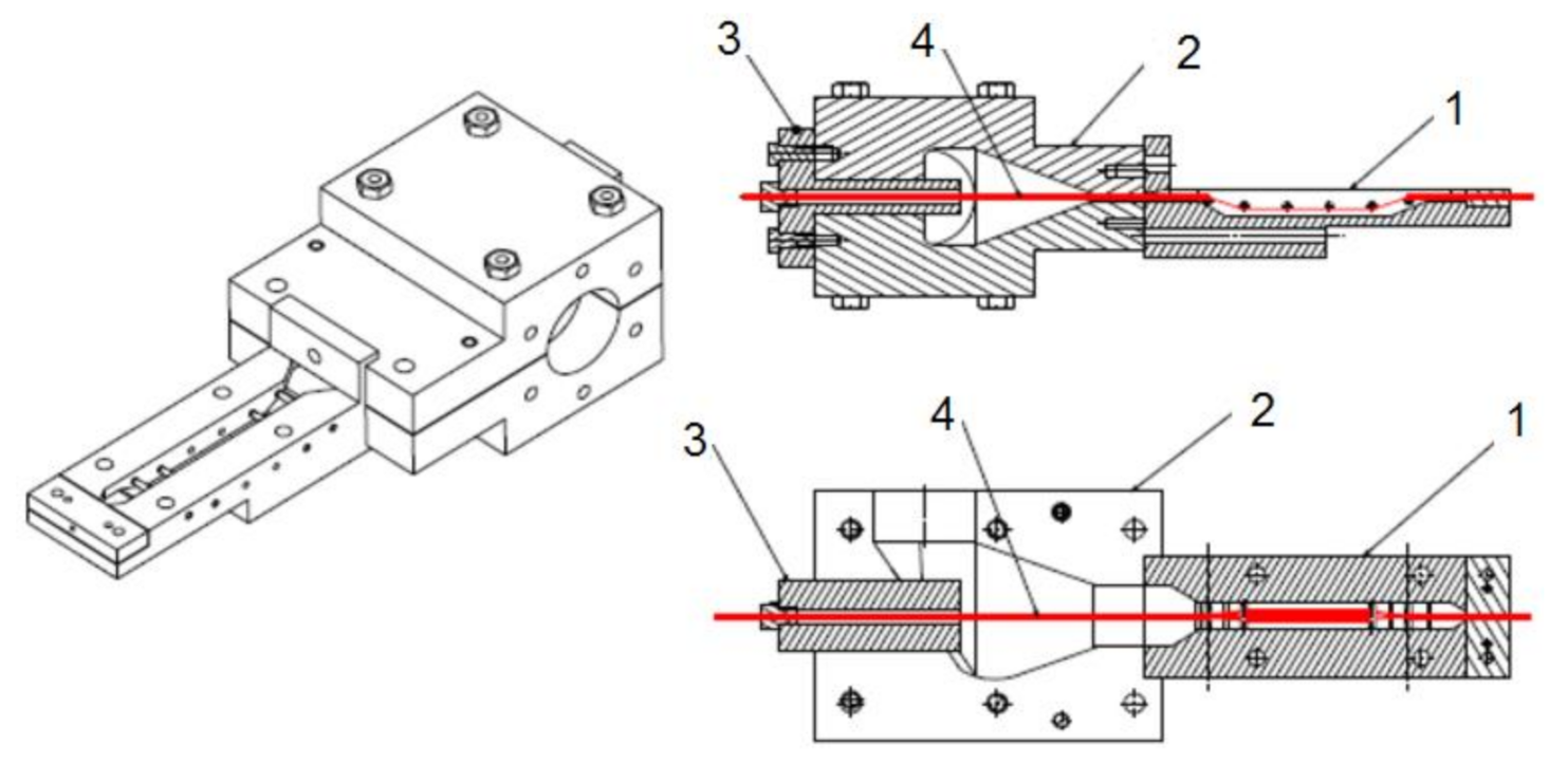
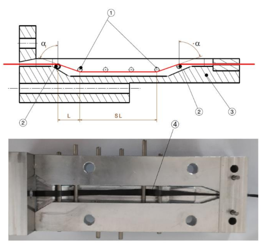
2.3. Design Features of Pultrusion Unit

In principle, this unit works to pull the impregnated fiber out of a cylindrical die using a pulling unit to form a fibrous composite filament. In the impregnation die, four spreading pins are installed where the fibers are passed from the upper side of pin 1 and pulled down to the bottom side of pin 2. The fibers are maintained until pin 3 and brought up to the die’s exit gate by pin 4. The impregnation dies’ design scheme is shown in Figure 4. The fiber will be compressed by the pin surface and spread sideways. This condition will allow the entire surface of the fiber to meet the matrix. Wilson [22] delivered a parameter model of the fiber bundle’s cross-section, the spread fiber bundle’s width, the distance between adjacent pins, and other related parameters, as shown in Equation (4). Impregnation dies with spreader pin positions and geometry refers to the theoretical calculations proposed by Wilson:
d = ( 12 A L cos α ) 3
where d is the width of the spread fiber bundle, A is the cross-section of the fiber bundle, L is the distance between tangential point of the fiber bundle and the adjacent pin, and α is the angle formed by the fiber bundle slope and the vertical line. The linear and angular positions of the spreader pin in the impregnated die were designed according to Equation (4) to obtain a wider stretched fiber in a transverse direction. SL (spreader length) is the distance between two spreader pins; it governs impregnation time.
The product is pulled out of the impregnation die by a so-called pulling unit device. Due to the influence of die swelling, the filament diameter that comes out of the die becomes larger than the die diameter. The pulling unit’s speed and position will control the cross-section diameter of the filament, fiber volume fraction, and fibers’ position on the cross-section of the filament. The design of the pulling unit is shown in Figure 5. The roller gap adjuster controls the gap between the rollers according to the diameter of the filament. The centering guide maintains the filament position to remain in line with the extruder axis; shifting this axis will cause a shifting position of the fiber against the matrix that surrounds it. The pressure exerted by the press roller will attract the filament by the pulling roller rotation; the speed controller can adjust this rotational speed.

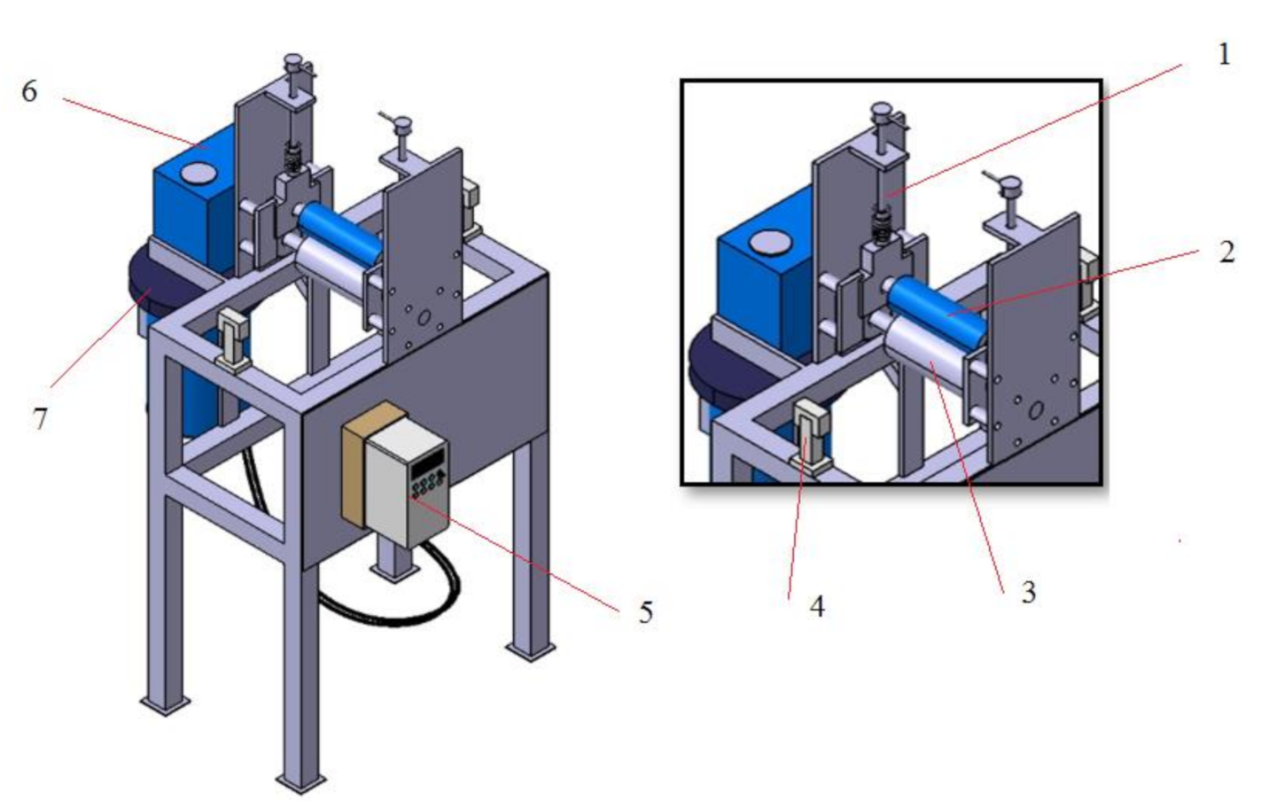
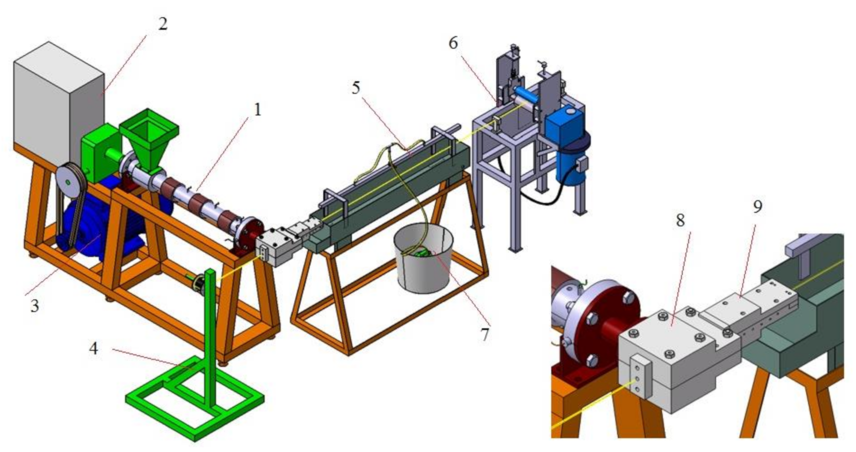
2.4. Total Assembly Design

Extrusion and pultrusion units were assembled completely into an extrusion–pultrusion machine; the complete design is shown in Figure 6. The fiber’s position was maintained in one axis from the fiber’s entry gate to the gap of the roller in the pulling unit. With a certain pull speed and always kept constant, the filament section’s diameter and shape could also be kept constant. The filament was always in the stretched condition and in-line with the die. Under these conditions, the use of an immersion cooling system was not possible. The cooling unit used a pumped water spray system; the spray water was collected in the tub and circulated back to the water container that had submerged the pump. After heading through the cooling process, the composite filament was wound on a sleeve. The filament rolls were then cut separately into pellets using a granulator.

2.5. Product Quality Testing

After building the machine based on the design, the machine performance was assessed by producing carbon fiber-reinforced PP filament and testing its quality. The product quality is indicated by cross-sectional area geometry, fiber volume fraction, impregnation quality, and interfacial shear strength between matrix and fiber. Linear and visual measurements evaluated the consistency of cross-sectional geometry. A pull-out test characterized the IFSS according to the ASTM D7913 standard, but the jig and experimental setup followed the method suggested by Joo et al. [24]. In this method, the pull-out specimen was clamped vertically into a specially designed metal frame, and the matrix envelope on the upper part of the specimen was peeled off so that only fibers were left, while at the bottom part, the shape of the composite remained. The upper part was clamped by the universal testing machine (20 KN UTM, Zwick/Roell, Germany) with a jaw grip; the crosshead speed was 100 mm/min. The upper part was considered the loaded end, whereas the bottom part was kept as a free end. Figure 7 shows the setup of pull-out testing. During tests, the load and the crosshead displacement were recorded, and the stress–strain diagram was plotted.
Scanning electron microscopy (EVO 10, Carl Zeiss Microscopy GmbH, Germany) was applied to the specimen’s cross-sectional surface to assess the morphological structure and the wetting condition between fibers and matrix. The small pieces of specimens were mounted in a vertical position on casted acrylic and gold-sputtered for 6 min before observation to prevent electrical charging during the examination. To attain a deeper examination at the micro-level, particularly the fiber condition, the magnification of 1000× to 7000× was set.
The fiber volume fraction and fiber mass fraction can be obtained with the help of theoretical calculation. When a void fraction is neglected, Equation (5) can be used to calculate the fiber volume fraction [25].
ν f = ρ c ρ m ρ f ρ m × 100 %
where ρc is the composite density, ρm is the matrix density, ρf is the fiber density, and νf is the fiber volume fraction.
To convert from volume fraction to mass fraction (wf), the following equation can be used:
w f =   ρ f ρ c v f

3. Results and Discussion

3.1. Calculating Machine Specification

Volumetric flow can be calculated based on Equation (1). There was no narrowing of barrel ends when meeting the secondary die entrance; therefore, the pressure drops, and leakage can be neglected. Table 1 shows the dimensions of the screw related to the volumetric flow. The screw speed could be varied from 0 to 50 rpm; it worked to supply the plastic melt to the melt pool, which had a volume of 34,295.4 mm3. In principle, the filament was made up of carbon fibers which were drawn through a melt pool carrying a small amount of plastic and coming out of the 2 mm die: due to low fluid requirements, a maximum screw speed was not required. Maximum screw speed will cause the volume of plastic melt to exceed the melt pool’s capacity and spill out of the die. The volumetric flow (QD) was calculated based on Equation (2); by setting a screw speed at 5 rpm, the volumetric flow is:
Q D = 38 × 7 × π × 38 × 5 × cos 19 2
QD = 76,274 mm3/min
According to those results above, the pool can be filled by volumetric flow in approximately 0.45 min from an empty state and will keep changing, so it does not go beyond the plastic residence time. Equation (7) is used to calculate the power required to drive the screw.
P = ρ × Q × C × T m T 0
where ρ is the density of plastic (kg/mm3) Q is the volumetric flow (mm3/min), C is the heat capacity of plastic (J/kg °C), Tm is the outlet temperature (°C), and T0 is the inlet temperature (°C).
In this case, the density of PP was 0.9 × 10⁻⁶ kg/mm3, and its heat capacity was 2100 J/kg K. The outlet temperature was 210 °C, whereas the inlet temperature was 35 °C. Then, the calculated power was:
P = 259,480 J/min = 4.32 kW = 5.9 HP
Considering the variety of plastic materials that can be processed in this machine, safety factor 2 was used in this design, so the motor’s power increased to 12 HP.

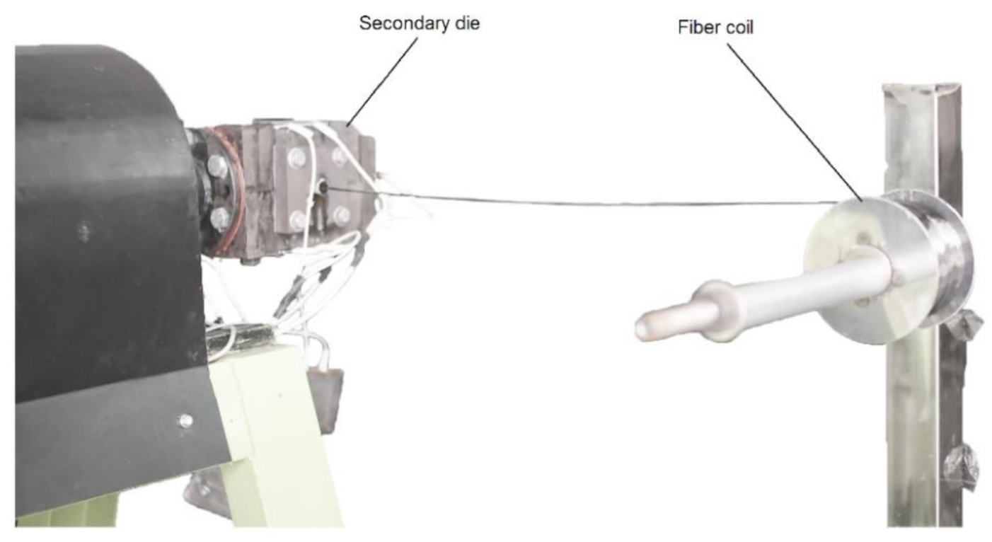
3.2. Impregnation Die

The main dimension of the impregnation die was manufactured according to Equation (4). It was targeted to obtain the width of fiber spreading (d) equal to the initial fiber width (7 mm). The fiber bundle entering the melt pool had a cylindrical cross-section with a diameter of around 2 mm; then, the cross-sectional area was 3.14 mm2. According to the design in Figure 4, the distance between the two tangential points of the fiber bundle and the adjacent pin (L) was 14 mm, then the rest of dimensions to be calculated were the angle between the fiber bundle slope and the vertical line (α).
α = cos 1 7 3 12 × 3.14 × 14
α = 49 °
The spreading condition of fibers was improved by the convex shape of the spreading pin [10], as shown in Figure 8. There were four pins attached to the die; two pins helped maintain the fibers in line with the die axis, while the rest acted as spreader pins. The distance between the two spreader pins (SL) was 82 mm. It was necessary to maintain the spread fibers for a longer impregnation time to achieve a better wetting effect. The impregnation of fibers occurred during contact with the pins where fiber bundles were spread out and open to receive the penetration thermoplastic melt. The impregnation time also depended on the pulling speed obtained from the pulling unit. A shear forces effect caused by pulling the fiber bundle over the pin immersed in the viscous molten polymer should be considered regarding the pulling unit’s work. The tensile strength of the fibers restricts the pulling force. The speed must be adjusted properly to avoid fiber breakage.

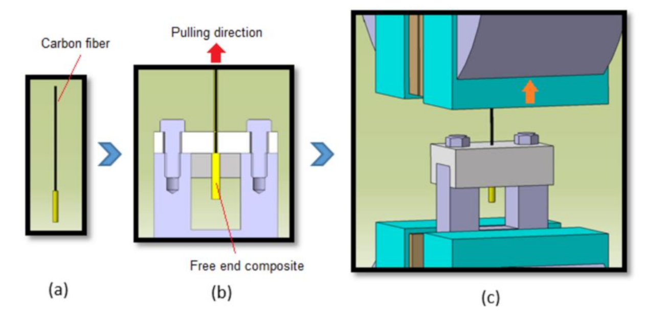
3.3. Processing of Specimen

The machine was successfully made according to the design. Machine performance was tested in the manufacture of carbon fiber-reinforced PP composites. The first step before composite processing was to apply the surface treatment on the carbon fiber. The silane coupling agent was mixed in distilled water, with a percentage of 1.5% (weight). Acetic acid was used to reduce the pH of the solution to 4.2. The solution was stirred evenly for 1 h to ensure a complete silane hydrolysis process [14]. Carbon fiber coils were immersed in the solution and heated at a temperature of 85 °C. Carbon fiber has no hydroxyl group content, which resulted in low adhesion to the matrix. The immersion process at elevated temperatures was expected to overcome the problem. For dispersing the coupling agent solution evenly over the fiber’s entire surface, the fiber wound slowly on two sleeves passed through a pin that was immersed in a solution, as shown in Figure 9. The fiber coils were rotated continuously for 1 h. Afterward, the fibers were washed in running water also by rolling them in the same device. Fiber coils were dried up in a forced air atmosphere at an elevated temperature of 80 °C for 1 h, and it was ensured that the fibers did not stick together and agglomerate. The treated fiber coils were fed to the secondary die and pulled together with a matrix out of the impregnation die (Figure 10).
The extrusion–pultrusion process is controlled by two variables, namely the treatment of raw materials and process parameters. The treatment variables can be the type of coupling agent, the duration and temperature of fiber immersion in the coupling agent solution, and moisture-sensitive materials such as nylon; it is also essential to consider drying before processing.
Process parameters that control product quality are screw speed, heating temperature, and filament pulling speed. The position and distance of spreader pins affect the fiber bend angle (α) and its spreading width; the condition is influenced by the impregnation’s design. Inside the impregnation die, the fiber bundles were pulled over the first pin, under the spreader pins, and finally over the fourth. Table 4 shows the process parameters used to produce carbon fiber-reinforced polypropylene. The screw speed was selected based on volumetric flow calculations adjusted to the volume requirements of plastic in the melt pool. The pulling speed value affects the filament diameter and the fiber volume fraction in the composite. Based on several experiments that have been carried out, a pulling speed of 56 mm/s can produce a filament diameter of about 2 mm. Nygård et al. [26] researched the effect of process parameters on glass fiber–polypropylene composites using the melt impregnation method. It was concluded that haul-off speeds of 3 m/min provided high impregnation efficiency. The heating temperature followed the recommendations from Table 2, which was in the range of 150–227 °C. Polypropylene is a hydrophobic material; therefore, plastic drying was not required. At this moment, the experiment was only to prove the machine’s capability to produce specimens of good quality; thus, parameter variations were not needed.
Fiber washing and drying are two essential steps during fiber treatment that greatly influence the quality of composite. Figure 11 shows the SEM results of unwashed and uncomplete dried fibers. Some amount of residual coupling agent solution debris was left in the composite. Moisturized fibers cannot be completely bonded to the matrix, indicated by the gap between the fiber and the matrix. This condition will undoubtedly reduce the mechanical properties of the composite.

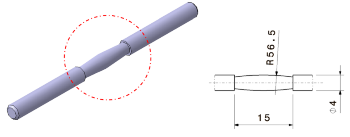
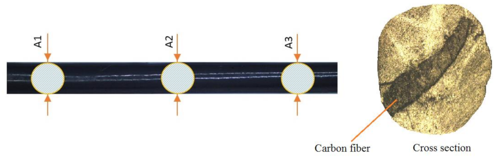
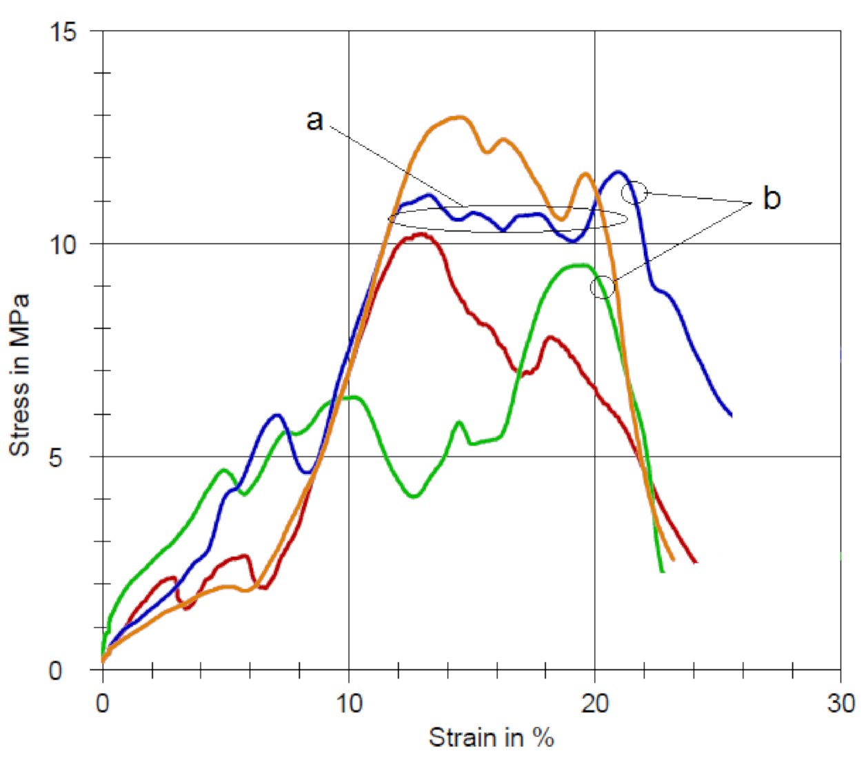
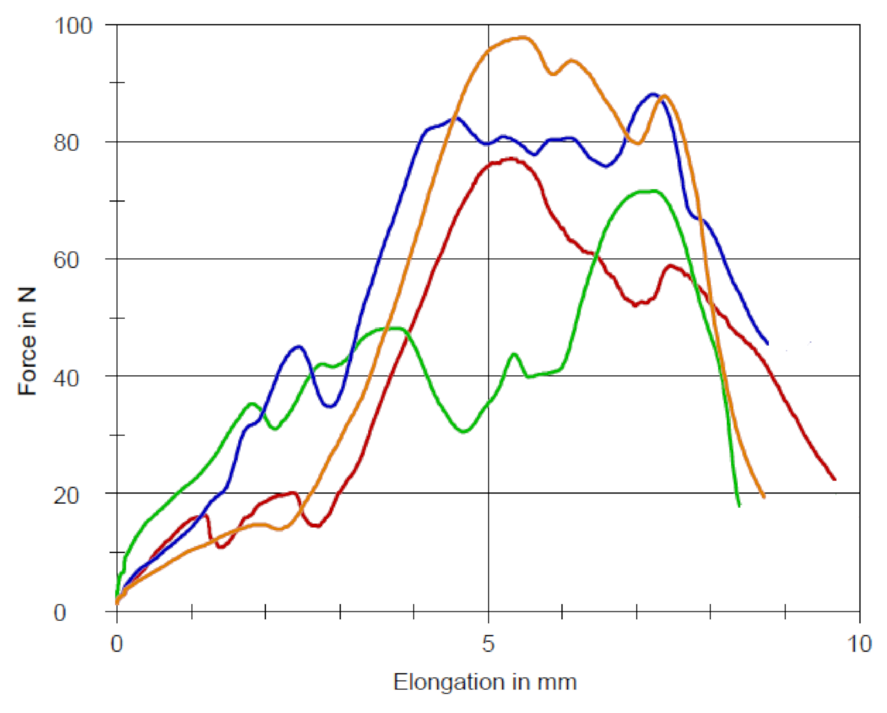
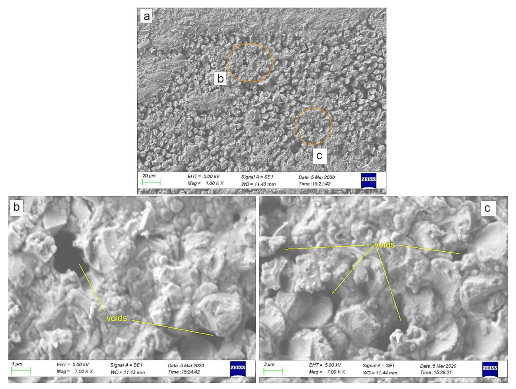
3.4. Specimen Measurement and Testing

Eight specimens were made using the parameters in Table 3; the specimens were cut to a length (L) of about 50 mm. The specimens were used to measure fiber volume fraction and to perform the pull-out test. Although the cylindrical die had a diameter of 3 mm, the cross-section of the filament undergoes a reduction in size and changes the cross-section into an oval shape. The cross-section reduction is influenced mainly by the pulling speed, while the pulling roller’s pressure influences the change in shape. Figure 12 shows the machine’s filament composite, whereas Table 5 describes the results of dimension measurement and calculation of fiber volume fraction. The cross-sectional diameter of the specimens was measured using a micrometer at three locations, namely A1, A2, and A3, then the area of each location was calculated. The average cross-sectional area of the specimen (Av) was calculated from these three areas. The volume fraction of fibers is calculated using Equation (5), and the composite density can be determined using the formula below:
ρ c = W A v × L
where ρc is the composite density, Av is the average cross-sectional area (cm2), L is the specimen length (cm), and W is the specimen weight (g).
The matrix fully covers the fibers, but the shape tends to be flat and does not follow the filament cross-section. The position and shape of fibers are mostly influenced by pulling speed and fiber guide position against the die axis.
At higher pulling speeds, where the material experiences a significant increase in temperature and a decrease in viscosity, the fiber position inside the die is shifted downstream [27]. These conditions do not directly affect the pellet’s quality, but, if necessary, modification of the die can improve the fiber’s position and shape. The eight samples used in Table 5 were obtained from the filament that was cut randomly (non-sequential). The machine can produce a composite filament with a stable weight and cross-section to obtain a uniform composite density. The average value of the fiber volume fraction was 20.3%, which can be increased by using multi-layer fiber feeding. The fiber content of composite pellets on the market is typically expressed as a mass fraction. Using Equation (6), the volume fraction of fibers can be converted into a mass fraction (wf):
w f = 1.8 1.08 × 20.3 %
wf = 33.9%
The mass fraction value is significant compared to the value of several types of PP/CF pellets on the market [28].
A pull-out test specimen was made by removing resin from the fiber along 40 mm, leaving 10 mm of the composite part. This remaining 10 mm of composite acted as a free end to hold the fiber against Zwick/Roell UTM’s pulling. A unique clamping device was used to hold the specimen; it was mounted on the UTM, as shown in Figure 7. The device has a central hole of 1 mm as a fiber entry gate before it is pulled out. The interfacial shear strength (IFSS) of the fiber–matrix can be seen from the pull-out test results in Figure 13 and Figure 14. The test was carried out on four identical samples with a length of 50 mm each. As shown in Figure 13a, the specimen stretched without increasing strength, caused by fibers sliding in the resin. Point b in Figure 13 shows that after maximum stress, the stress gradually decreased. It indicates that the bond between the fiber and the matrix began to loosen, then the fiber was pulled out of the matrix envelope. Similarly to Figure 13, Figure 14 shows a load–elongation curve. The increase in load at the start of the test is similar to that shown in Figure 13, where debonding covers the entire embedded length prior to the failure of the bundle. After the peak value, the load decreases sharply to attain a lower rate of decrease when the bundle is pulled out through its total length.
The maximum IFSS could reach 12.94 MPa, and the average value was 11.05 MPa. The test results showed that the fiber–matrix bonding quality is good. As a comparison with these results, Zhang et al. [29] conducted IFSS investigation on carbon fiber-reinforced polypropylene. For conventional CF/PP composites (without nucleating agents), the IFSS value was only 6.8 MPa. Additional nucleating agents increased IFSS to 13.4 MPa. Tanaka et al. [30] evaluated the PP modification’s influence on the fiber–matrix IFSS of CF/PP composites. The IFSS values of CF/unmodified PP and CF/medium polar modified PP was 11.3 MPa and 13.5 MPa, respectively.
The result above was verified by SEM analysis, as shown in Figure 15. It was confirmed that the high quality of fiber impregnation obtained the high IFSS of the composite. The fiber was fully covered and wetted by the matrix. However, some voids were still found. This condition can be explained by the fact that the matrix experienced high viscosity during the process due to the low processing temperature. The viscous plastic melt cannot penetrate those voids appropriately. The melt viscosity can be reduced by increasing the processing temperature and speed [31]. This simultaneously minimizes the occurrence of voids inside the composite.

4. Conclusions

The manufacturing and performance testing of the extrusion–pultrusion machine has been carried out successfully. The machine could produce filaments with a uniform geometry and dimension. The volume fraction of the composite filaments could reach 20.3% with good impregnation quality. Fiber surface treatment and the use of innovative design of the impregnation dies, which were equipped with spreader pins, resulted in a uniform impregnation effect on the fiber. Almost all fibers were covered (“wet-out”) by the matrix, hardly showing any gaps in the filament cross-section. The quality of impregnation was evidenced by the achievement of an average IFSS of 11.05 MPa, which is considerably high. Filaments with sufficient impregnation quality and volume fraction can be used as pellets for manufacturing structural composite products. Nevertheless, further research is still needed on this developed system, such as the variation of die design, fiber treatment, type of resin, and optimization of the processing parameters.

Author Contributions

Conceptualization, H.S.B.R.; data curation, H.S.B.R.; funding acquisition, H.S.B.R.; investigation, C.B.; methodology, C.B.; project administration, G.N.; resources, G.N.; software, C.B.; supervision, H.S.B.R. and G.N.; validation, G.N.; writing—original draft preparation, C.B.; writing—review and editing, H.S.B.R. and G.N. All authors have read and agreed to the published version of the manuscript.

Funding

This research was funded by the Ministry of Research and Technology/National Research and Innovation Agency of the Republic of Indonesia.

Institutional Review Board Statement

Not applicable.

Informed Consent Statement

Not applicable.

Data Availability Statement

Not applicable.

Acknowledgments

The authors would like to acknowledge the Department of Mechanical and Industrial Engineering, Universitas Gadjah Mada Yogyakarta, and the Department of Mechanical Engineering Universitas Muhammadiyah Yogyakarta for supporting the materials and equipment used in the experiment.

Conflicts of Interest

The authors declare no conflict of interest.

References

  1. Ren, P.; Dai, G. Fiber Dispersion, and Breakage in Deep Screw Channel during Processing of Long Fiber-reinforced Polypropylene. Fibers Polym. 2014, 15, 1507–1516. [Google Scholar] [CrossRef]
  2. Baillif, L.M. The Effect of Processing on Fiber Dispersion, Fiber Length, and Thermal Degradation of Bleached Sulfite Cellulose Fiber Polypropylene Composites. J. Thermoplast. Compos. Mater. 2009, 22, 115–133. [Google Scholar] [CrossRef]
  3. Hietala, M.; Oksman, K. Pelletized cellulose fibers used in twin-screw extrusion for biocomposite manufacturing: Fibre breakage and dispersion. Compos. Part A 2018, 109, 538–545. [Google Scholar] [CrossRef]
  4. Kutz, M. Applied Plastics Engineering Handbook: Processing, Materials, and Applications; William Andrew: Oxford, UK, 2011. [Google Scholar]
  5. Henninger, F.H. Beitrag zur Entwicklung neuartiger Fertigungsverfahren zur Herstellung von Bauteilen aus kontinuierlich faserverstärkten Thermoplasten Danksagung; Technischen Universität Kaiserslautern: Kaiserslautern, Germany, 2005. [Google Scholar]
  6. Köhler, T.; Röding, T.; Gries, T.; Seide, G. An Overview of Impregnation Methods for Carbon Fibre Reinforced Thermoplastics. Key Eng. Mater. 2017, 742, 473–481. [Google Scholar] [CrossRef] [Green Version]
  7. Peltonen, P.; Lahteenkorva, K.; Paakkonen, E.J.; Jarvela, P.K.; Tormala, P. Composite Materials Impregnation of a Polypropylene/Glass. J. Thermoplast. Compos. Mater. 1992, 5, 318–341. [Google Scholar] [CrossRef]
  8. Ho, K.K.C.; Shamsuddin, S.R.; Riaz, S.; Lamorinere, S.; Tran, M.Q.; Javaid, A.; Bismarck, A. Wet impregnation as route to unidirectional carbon fibre reinforced thermoplastic composites manufacturing. Plast. Rubber Compos. 2011, 40, 100–107. [Google Scholar] [CrossRef]
  9. Ren, F.; Yu, Y.; Cao, M.; Li, Y.; Xin, C.; He, Y. Effect of pneumatic spreading on impregnation and fiber fracture of continuous fiber-reinforced thermoplastic composites. J. Reinf. Plast. Compos. 2017, 36, 1554–1563. [Google Scholar] [CrossRef]
  10. Awaji, F.; Gilbert, M.; Kelly, G.; Fox, B.; Pigram, P.J. Adhesion of polymers. Prog. Polym. Sci. 2009, 34, 948–968. [Google Scholar] [CrossRef]
  11. Wenzhong, N. The effect of coupling agents on the mechanical properties of carbon fiber-reinforced polyimide composites. J. Thermoplast. Compos. Mater. 2015, 28, 1572–1582. [Google Scholar] [CrossRef]
  12. Han, S.H.; Oh, H.J.; Kim, S.S. Evaluation of fiber surface treatment on the interfacial behavior of carbon fiber-reinforced polypropylene composites. Compos. Part B 2014, 60, 98–105. [Google Scholar] [CrossRef]
  13. Shi, P.; Wu, W.; Chen, Y.; Liu, M.; Liu, Y. Influence of Fiber Surface Treatment on Mechanical Properties of CF/PET Composites. J. Macromol. Sci. 2012, 51, 1485–1497. [Google Scholar] [CrossRef]
  14. Marissen, R.; Van Der Drift, L.T.; Sterk, J. Technology for rapid impregnation of fibre bundles with a molten thermoplastic polymer. Compos. Sci. Technol. 2000, 60, 2029–2034. [Google Scholar] [CrossRef]
  15. Zolfaghari, A.; Behravesh, A.H.; Adli, A.; Sarabi, M.T. Continuous glass fiber reinforced wood plastic composite in extrusion process: Feasibility and processing. J. Reinf. Plast. Compos. 2013, 32, 52–60. [Google Scholar] [CrossRef]
  16. Wang, J.; Song, F.; Yu, M. Unidirectional continuous fiber-reinforced polypropylene single-polymer composites prepared by extrusion– calendering process. J. Thermoplast. Compos. Mater. 2019, 1–17. [Google Scholar] [CrossRef]
  17. Sumitomo, C. Cosmoplene® AW564 Technical Data Sheet; The Polyolefin CoMPany (Singapore) Pte Ltd.: Singapore, 2019. [Google Scholar]
  18. Torayca T700S Data Sheet, No. CFA-005. Available online: https://www.toraycma.com (accessed on 3 June 2020).
  19. γ-Amino Propyl Triethoxy Silane (APTS). Available online: http://www.jessicachem.com (accessed on 31 May 2020).
  20. Rosen, M.; Kiani, A. The Role of Plastics Compounding for Injection Molding. Plast. Eng. 2016, 72, 24–28. [Google Scholar] [CrossRef]
  21. Giles, H.F. Extrusion: The Definitive Processing Guide; William Andrew, Inc.: New York, NY, USA, 2005. [Google Scholar]
  22. Wilson, S.D.R. Lateral spreading of fibre tows. J. Eng. Math. 1997, 32, 19–26. [Google Scholar] [CrossRef]
  23. Budiyantoro, C.; Rochardjo, H.S.B.; Nugroho, G. Effects of Processing Variables of Extrusion–Pultrusion Method on the Impregnation Quality of Thermoplastic Composite Filaments. Polymers 2020, 12, 2833. [Google Scholar] [CrossRef] [PubMed]
  24. Joo, S.; Yu, M.; Stock, W.; Lee, J.; Kim, H. Design and manufacture of automotive composite front bumper assemble component considering interfacial bond characteristics between over-molded chopped glass fiber polypropylene and continuous glass fiber polypropylene composite. Compos. Struct. 2020, 236, 1–10. [Google Scholar] [CrossRef]
  25. Gibson, R.F. Principles of Composite Material Mechanics, 3rd ed; CRC Press: New York, NY, USA, 1994. [Google Scholar]
  26. Nygård, P.; Gustafson, C.G. Continuous glass fiber–polypropylene composites made by melt impregnation: Influence of processing method. J. Thermoplast. Compos. Mater. 2004, 17, 167–184. [Google Scholar] [CrossRef]
  27. Tucci, F.; Rubino, F.; Esperto, V.; Carlone, P. Integrated modeling of injection pultrusion. Proceedings of The 22nd International Esaform Conference On Material Forming, Vitoria-Gasteiz, Spain, 8–10 May 2019; pp. 1–6. [Google Scholar]
  28. Complēt® LCF30-PP. In Product Data Sheet; PlastiComp, Inc.: Winona, MI, USA; Available online: https://www.plasticomp.com/news/ (accessed on 31 January 2021).
  29. Zhang, K.; Li, Y.; He, X.; Nie, M.; Wang, Q. Mechanical interlock effect between polypropylene/carbon fiber composite generated by interfacial branched fibers. Compos.Sci. Technol. 2018, 167, 1–6. [Google Scholar] [CrossRef]
  30. Tanaka, K.; Ohno, K.; Katayama, T. Effects of PP modification and processing time on fiber/matrix interfacial strength for carbon fiber reinforced polypropylene. In Proceedings of the 2 International Conference on High Performance and Optimum Design of Structures and Materials (HPSM 2016), Siena, Italy, 19–21 September 2016; pp. 329–334. [Google Scholar]
  31. Wiedmer, S.; Manolesos, M. An Experimental Study of the Pultrusion of Carbon Fiber-Polyamide 12 Yarn. J. Thermoplast. Compos. Mater. 2006, 19, 97–111. [Google Scholar] [CrossRef] [Green Version]
Figure 1. Screw design (all dimensions are in mm).
Machines 09 00042 g001
Figure 2. Die design: (1) impregnation die; (2) secondary die; (3) fiber guide; (4) carbon fiber.
Machines 09 00042 g002
Figure 3. Screw dimension related to volumetric drag flow and pressure flow rates calculation [21].
Machines 09 00042 g003
Figure 4. Bottom impregnation die design: (1) spreader pins; (2) centering pins; (3) bottom die; (4) spreaded fiber.
Machines 09 00042 g004
Figure 5. Pulling unit: (1) roller gap adjuster; (2) press roller; (3) pulling roller; (4) centering guide; (5) speed control; (6) speed reducer; (7) motor.
Machines 09 00042 g005
Figure 6. Total assembly design: (1) extruder; (2) main control; (3) driving unit; (4) fiber feeder; (5) cooling bath; (6) pulling unit; (7) cooling pump; (8) secondary die; (9) impregnation die [23].
Machines 09 00042 g006
Figure 7. Pull-out test: (a) peeled off specimen; (b) clamping device; (c) testing [23].
Machines 09 00042 g007
Figure 8. Convex shaped spreader pin (all dimensions are in mm).
Machines 09 00042 g008
Figure 9. Fiber immersion device.
Machines 09 00042 g009
Figure 10. Fiber feeding.
Machines 09 00042 g010
Figure 11. Effect of unwashed and uncomplete dried fibers: (a) CA debris appeared; (b) gaps between fiber and matrix.
Machines 09 00042 g011
Figure 12. Measuring the cross-section of composite filament.
Machines 09 00042 g012
Figure 13. Pull-out test results: (a) fiber slide; (b) pull out starting point.
Machines 09 00042 g013
Figure 14. Pull-out curves (in Load–Elongation mode).
Machines 09 00042 g014
Figure 15. SEM images of CFR-PP: (a) 1000× magnification; (b) border section; (c) middle section.
Machines 09 00042 g015
Table 1. Material properties.
MaterialPropertiesValues
Carbon fiber (T700SC 12K)Filament diameter (µm)7
Density (g/cm3)1.8
Tensile strength (MPa)4900
Cosmoplene AW564-PPDensity (g/cm3)0.9
Cylinder temperature (°C)190–230
Tensile strength at yield (MPa)27.5
Tensile strength at break (MPa)23
Melt Flow Rate (g/10 min)9
VinyltrimethoxysilaneDensity (g/cm3)0.978
Table 2. Spreading width calculation.
SymbolParameterValues
WChannel width (mm)38
HChannel height (mm)7
DScrew diameter (mm)38
NScrew speed (rpm)50
αHelix angle (°)19
Table 3. The heating temperature of various thermoplastics.
MaterialHeating Zone 1 (°C)Heating Zone 2 (°C)Heating Zone 3 (°C)Die (°C)
Polypropylene150–180204–227204–227204–227
HDPE149–171177–199199–216199–216
Nylon 6221–249249–271266–288266–288
ABS177–193199–216216–240216–240
Polycarbonate171–193210–232227–260227–260
Table 4. Processing parameters.
ParameterValuesUnit
Screw speed5rpm
Heating temperature210—180—150°C
(Die—barrel zone 1—barrel zone 2)
Pulling speed56mm/s
Table 5. Fiber volume fraction measurements.
No.L (mm)W (g)Cross-Section Area (mm2)ρc (g/cm3)νf (%)
A1A2A3Av
149.40.173.173.123.373.221.0719.4
250.60.172.933.193.073.061.1021.8
348.50.162.822.933.142.961.1123.8
448.50.163.043.003.213.081.0718.9
549.10.173.303.223.143.221.0819.5
648.30.173.343.273.313.311.0618.2
748.80.173.173.203.303.221.1022.1
848.60.163.193.143.203.181.0718.8
Average of fiber volume fraction20.3
L: specimen length; W: specimen weight; Av: average cross-section area; ρc: composite density; νf: fiber volume fraction.
Publisher’s Note: MDPI stays neutral with regard to jurisdictional claims in published maps and institutional affiliations.

