
Design for the Automation of an AMBU Spur II Manual Respirator
by

Carles Domènech-Mestres
1, 
Elena Blanco-Romero
1, 
Albert de la Fuente-Morató
1 and 
Manuel Ayala-Chauvin
2,*
1
Centre de Disseny d’Equips Industrials, Universitat Politècnica de Catalunya, 08028 Barcelona, Spain
2
SISAu Research Group, Facultad de Ingeniería y Tecnologías de la Información y Comunicación, Universidad Tecnológica Indoamérica, Ambato 180103, Ecuador
*
Author to whom correspondence should be addressed.
Machines 2021, 9(2), 45; https://0-doi-org.brum.beds.ac.uk/10.3390/machines9020045
Submission received: 10 January 2021
/
Revised: 9 February 2021
/
Accepted: 10 February 2021
/
Published: 21 February 2021
(This article belongs to the Section Automation and Control Systems)
Abstract
:This article shows the design of a device to automatize an Ambu Spur II manual respirator. The aim of this compassionate medicine device is to provide an emergency alternative to conventional electric respirators—which are in much shortage—during the present COVID-19 pandemic. To develop the device, the classical method of product design based on concurrent engineering has been employed. First, the specifications of the machine have been determined, including the function determining the air volume provided at every moment of the breathing cycle; second, an adequate compression mechanism has been designed; third, the control circuit of the motor has been determined, which can be operated via a touchscreen and which includes sensor feedback; fourth, the device has been materialized with readily available materials and market components, mostly of low cost; and fifth, the machine has been successfully tested, complying with sanitary regulations and operating within desirable ranges. The device has been already manufactured to supply respirators to several hospitals around the Catalan Autonomous Community in Spain, but can also be replicated in developing countries such as Ecuador.
1. Introduction
Mechanical ventilation is the short-term, vital support technique most widely used worldwide. It is employed every day with patients with respiratory failure, as well as with heavily sedated patients in standard surgical procedures. The present medical crisis generated by the COVID-19 pandemic has caused a spike in respiratory failure cases that need mechanical respirators, which has triggered a shortage of such devices worldwide [1,2,3]. These shortages have led to serious consequences, especially in densely populated cities, with cases where people have had to operate manual, handheld respirators for protracted periods of time [4].
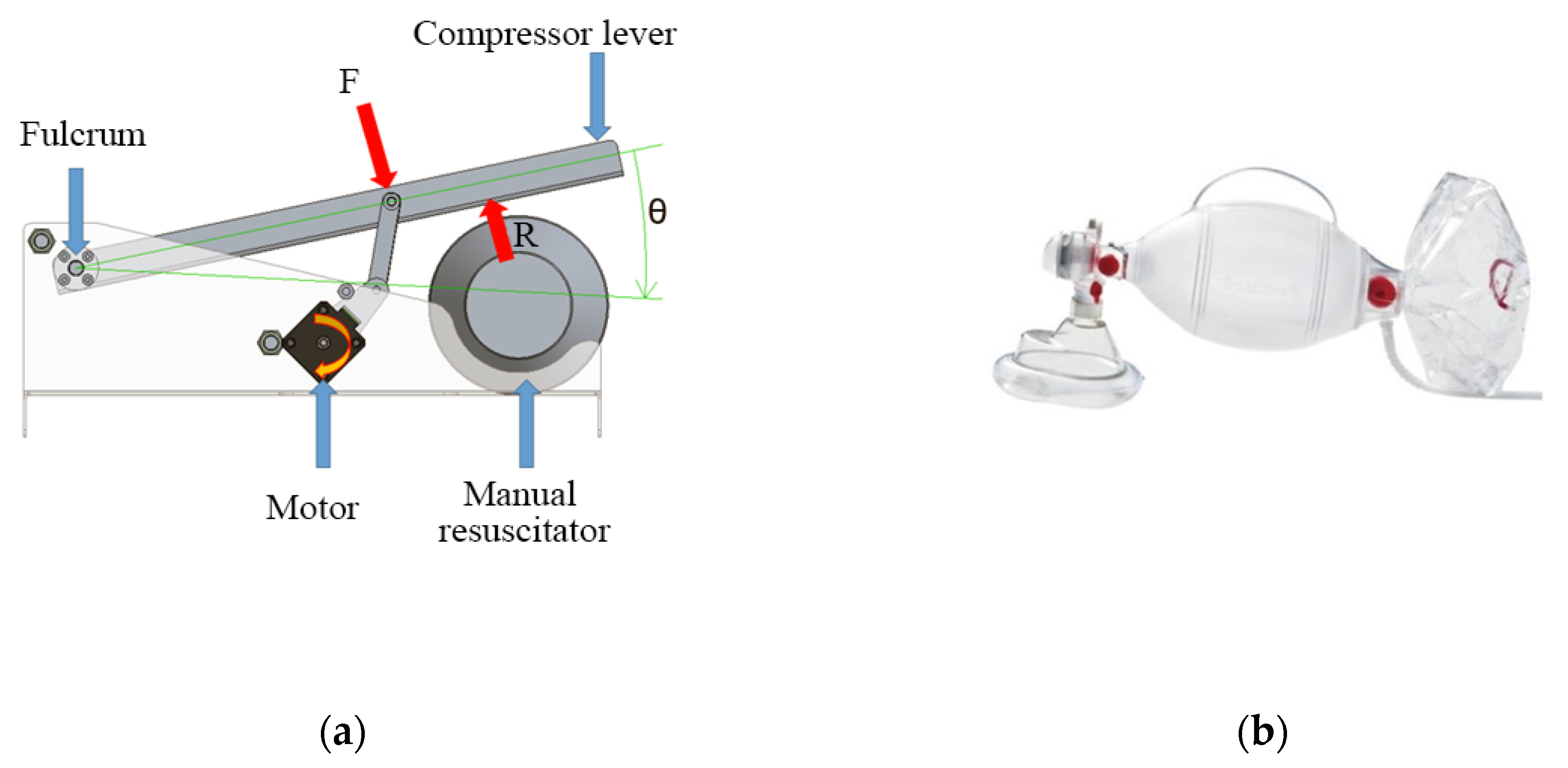
A manual respirator is a device that consists of a tube with a funnel-like face mask, an oval silicone bag, and a one-way valve that acts as the air inlet (see Figure 4b). When the bag is compressed repeatedly by an operator’s hand, it assists the patient with their breathing cycle [5]. These devices exist in various sizes that suit different ages and air volumes [6,7]. Manual respirators are meant to be used only during emergencies, given the inconvenience of requiring the constant implication of an operator that can become exhausted after protracted periods of time [8,9,10]. This also has the inconvenience of not letting the operator, usually a medical staffer, attend to other patients.
Since this is a manual device, it is impossible to control exactly the respiration parameters, such as the frequency of the cycle and the inspiration volume. The exact airflow vs. time curve that would suit a person best cannot be followed exactly either, unlike in an automatic respirator [11]. Some manual respirators are equipped with a pressure valve, which protects the patient’s lungs from overpressure, while other complements can be used to ensure a minimum threshold pressure throughout the cycle (PEEP valves) [12]. Expired gasses, except for a few special cases like divided respirators, are released to the atmosphere without any processing [13].
Automatized manual respirators, like the one described in this article, consist of a manual respirator and a compression device that automatically performs the respiration cycles [14]. While the lack of fine control over the breathing cycle (like any manual respirator) makes their long-term use not recommendable, automatized manual respirators still have the advantage of not needing the constant engagement of an operator, so they can be useful in emergencies in isolated zones, field hospitals, or poor regions [15]. The compression mechanism can also allow for the breathing cycle parameters to be loosely controlled with some sensors.
While a few models comparable to this article’s device do exist, there is no widely available commercial product capable of performing anything remotely similar. Given the present need for respirators for the pandemic, a great number of initiatives have been launched to solve this problem. Many low-cost, open-source devices have been created by researchers [16,17,18,19]. Some of such devices include OxyGEN [20], ResUHUrge [21], and Leitat [22], all of which have already been validated with patient trials. Furthermore, some older designs also exist, such as those from MIT [23].
Most of these respirators consist of a manual respirator with a compression system that controls some of the breathing cycle parameters and monitors some of the variables. Many of these control systems are purely mechanical (i.e., with no control electronics), so any modification of the breathing cycle parameters entails changing mechanical components such as cams or gears. All of this makes them rough and sometimes unreliable since the minimal resistance requirements and safety regulations are not always met [24].
On the other hand, the device in this article presents the advantages of implementing an electronic control system that can be modified with far greater flexibility while also allowing for more exact monitoring of the cycle. Furthermore, all the materials have been selected according to exact resistance criteria and complying with sanitary regulations.
2. Materials and Methods
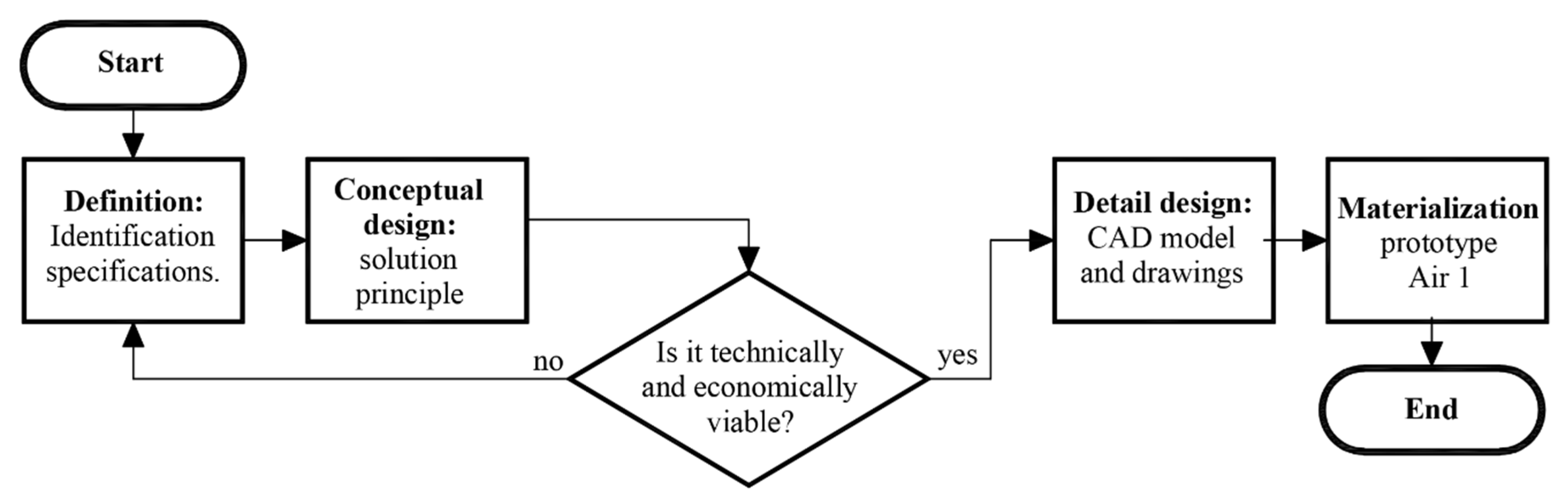
For the device’s design and fabrication process, the principles of concurrent engineering have been applied, where the design of products and processes are integrated in parallel. The following stages of the method are; (1) definitions, (2) conceptual design, (3) detail design, and (4) materialization design. Figure 1 shows the conceptual flowchart of this method.
However, it must be emphasized that before starting with any of the phases of the classical design method, an additional contextual analysis needs to be performed, where the economic and technical feasibility of the project must be in accordance with the geographical place where the process will be implemented.
2.1. Requirements
To ensure the correct implementation of the patient’s breathing cycle, the following requisites must be fulfilled:
- Provide a volume of 300 mL to 500 mL of air (or oxygenated mix) per breathing cycle.
- Maintain a positive end-expiratory pressure (PEEP) at a range between 5 cm H2O and 25 cm H2O. The PEEP is the pressure in the lungs above atmospheric pressure that exists at the end of expiration. This requisite is currently already implemented with a valve included in the manual respirator by default.
- Maintain the peak pressure at a range between 18 cm H2O and 40 cm H2O.
- Maintain the breathing cycle at about 15 respirations per minute.
- Divide the cycle into phases: inspiration (with an abrupt initial ramp), expiration (less abrupt), and a pause.
Additionally, to ensure the correct operation of the system, the following aspects must be monitored:
- Pressure provided by the AMBU in real-time
- Airflow provided by the AMBU in real-time (from which the delivered volume can be calculated).
The designed system must fulfil all these requirements while also keeping costs as low as possible and using standard commercial components.
2.2. Conceptual Design
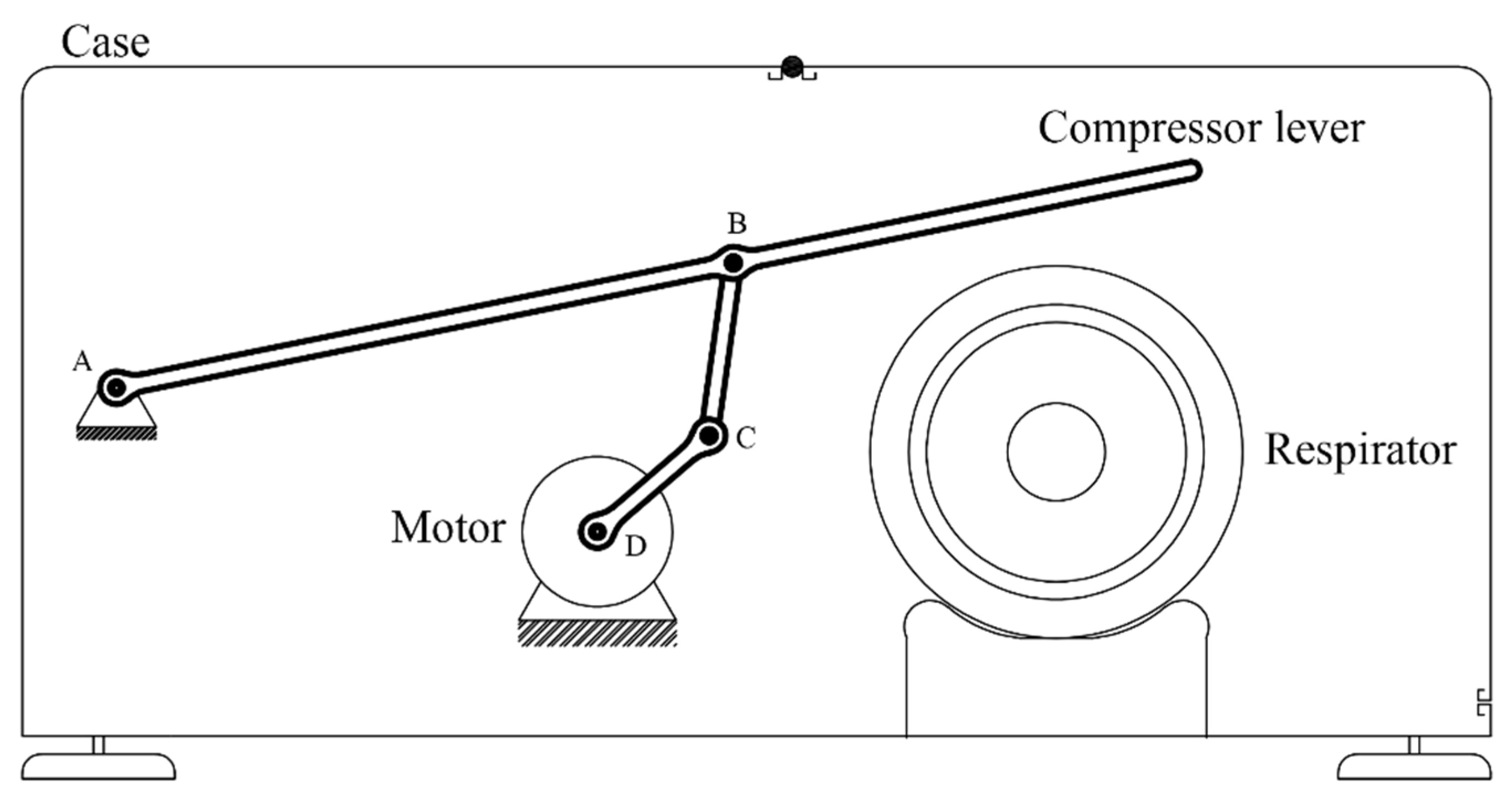
The system will consist of a manual respirator and—in order to perform a breathing cycle—a device to compress it. The compression mechanism will consist of a lever operated by an electrical motor via a four-bar linkage mechanism.
First of all, the parameters that define the breathing cycle will be determined (frequency, duration of each phase, etc.), from which the temporal evolution of the height of the compressor lever h will be extracted. Secondly, adequate dimensional parameters of the mechanism (bar lengths, positions) will be determined, from which the temporal evolution of the angle of the motor will be extracted. Finally, an adequate electronic control system will be determined, with custom-built software, sensors, and selectors to modify the breathing cycle parameters. Figure 2 shows the conceptual design of the device. The mechanism is composed of a lever operated with a motor by means of a four-bar linkage. Point A is the fulcrum of the lever, while point D is the axle of the motor. The end of the lever compresses the respirator, and the height of this end can be controlled by the rotation angle of the motor. The compression height is approximately proportional to the air volume delivered to the patient’s lugs. Therefore, by controlling the rotation angle of the motor, the volume of air delivered to the patient can be adjusted according to a pre-established breathing cycle.
Unlike mechanisms employing cams, this concept has the advantage of greater flexibility, since the air intake can be easily modified by the software operating the motor. It also has the added bonus of employing fewer movable parts, thus, decreasing the overall complexity, easing the standardization most components, and allowing for the possibility to be adapted to different sizes.
2.2.1. Breathing Cycle
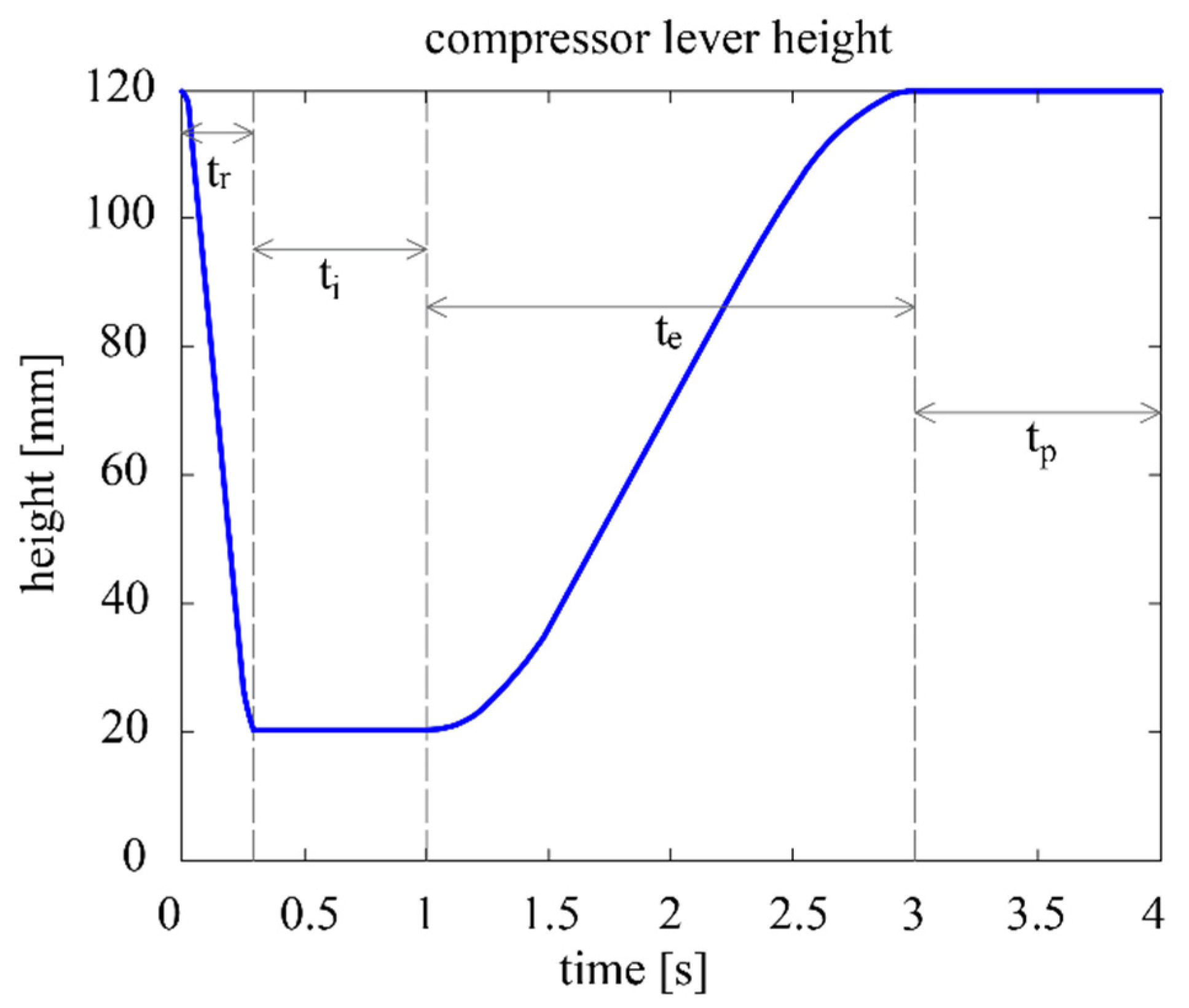
The contact point between the compression lever and the respirator is denoted as E, while the height from the base of the device up to E is denoted as h. The air volume delivered in each breathing cycle is determined by the maximum and minimum heights of E, and . The duration of the cycle is parameterized as , which is the inverse of the breathing frequency in cycles/min. After consulting the literature, the following concept of the parametric breathing cycle is established (see also Figure 3) [25,26]:
- Inspiration phase, divided into two subphases:
- 1.1
- Ramp subphase: the lever starts at and swiftly compresses the respirator until the compression reaches and the desired volume is be delivered to the patient. The duration of this subphase is the inspiration time , which remains at 0.3 s regardless of the cycle.
- 1.2
- Inspiration proper subphase: the air is delivered to the patient’s respiratory system, where it remains for a short time to ensure adequate oxygen absorption. The total duration of the inspiration phase (thus including ) is the inspiration time , which corresponds to 25% of .
- Expiration phase: the lever rises until reaching , and the respirator is progressively decompressed until its initial shape is reached. This phase is considerably less abrupt than the ramp subphase. The duration of the expiration phase is the expiration time , which corresponds to 50% of .
- Pause phase: The lever remains stationary at for the rest of the cycle. The duration of this phase is the expiration time , which corresponds to 25% of .
The curve that determines the evolution of height of h(t) is defined as a piecewise function. Each of the four segments of this function corresponds to the initial two subphases plus the other two phases of the cycle. Segments 1 and 3 correspond to constant functions with the minimum and maximum heights of the lever, respectively. Segments 1 and 3 are cubic functions defined by the coefficients a1…a4 and a5…a8, respectively. The values of these coefficients are determined by ensuring that the whole curve is continuous and derivable. The curve will thus have an equation of the following kind:
Once the desired height of the lever at every moment of the cycle is determined, the algorithm will now calculate the rotation of the stepper motor required to reach those heights.
2.2.2. Mechanism
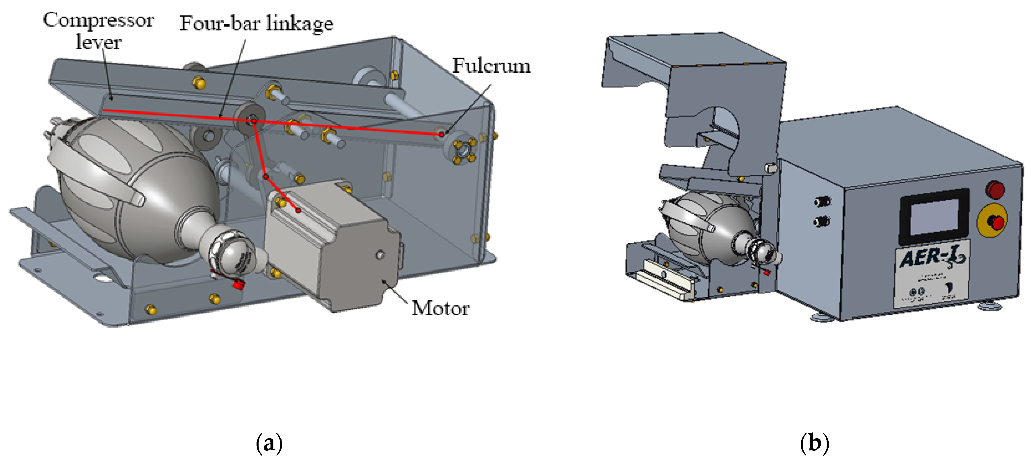
The mechanism to automatize the respirator is based on the four-bar linkage shown in Figure 4a. Figure 4b shows an AMBU Spur II manual respirator.
Once the desired compression height function h(t) is determined [27], now the necessary rotation of the motor will be found.
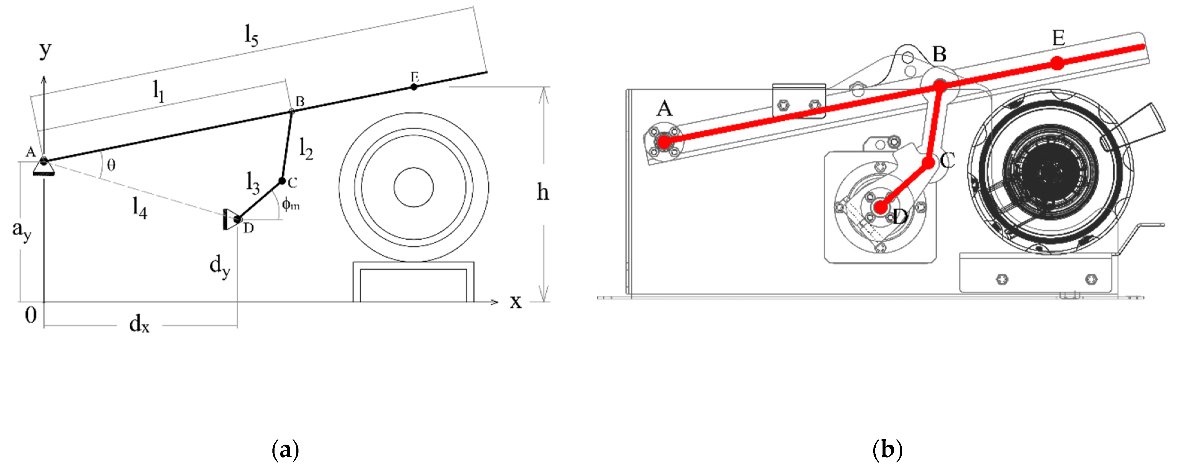
Figure 5a displays the conceptual design of the mechanism. The fulcrum of the compressor lever is at A. The vertical projection of this point to the ground will be the origin of the coordinate system O, with axes x and y, as the image shows. With this coordinate system, the coordinates of the static points A, D of the ground link will be described with the parameters ax, ay, dx, and dy.
The other parameters and variables of the mechanism will be as follows:
- The output link, with ends at A and B, has a length l1. The output link is part of the compression lever, which also includes the contact point with the respirator E. The distance between A and E is l5. The vertical coordinate of point E is the compression height h(t).
- The floating link has ends at B and C, and its length is l2.
- The input link has ends at C and D, and its length is l3. The motor rotates the shaft of the input link at D. The angle between the input link and the ground is .
Figure 5b shows the drawing of the detail design with the conceptual mechanism superimposed.
Once all the parameters and variables are determined, the short mathematical model to relate h(t) and will be as follows:
First, the static points A and D are defined by their parametric position vectors in the previously defined coordinate system:
Figure 5a,b show some auxiliary variables used to solve the model. The distance between A and D corresponds to the length of the ground link of the four-bar mechanism:
The inclination angle respect the horizontal θb of segment AB is (all angles in radian):
In a similar fashion, the inclination angle θr of segment AD is:
The combination of these angles will thus be the angle between segments AB and AD:
The distance f between points B and D will thus be:
With the law of cosines, angles and can be determined as:
By combining these two angles and , the angle of the motor respect the horizontal can be found:
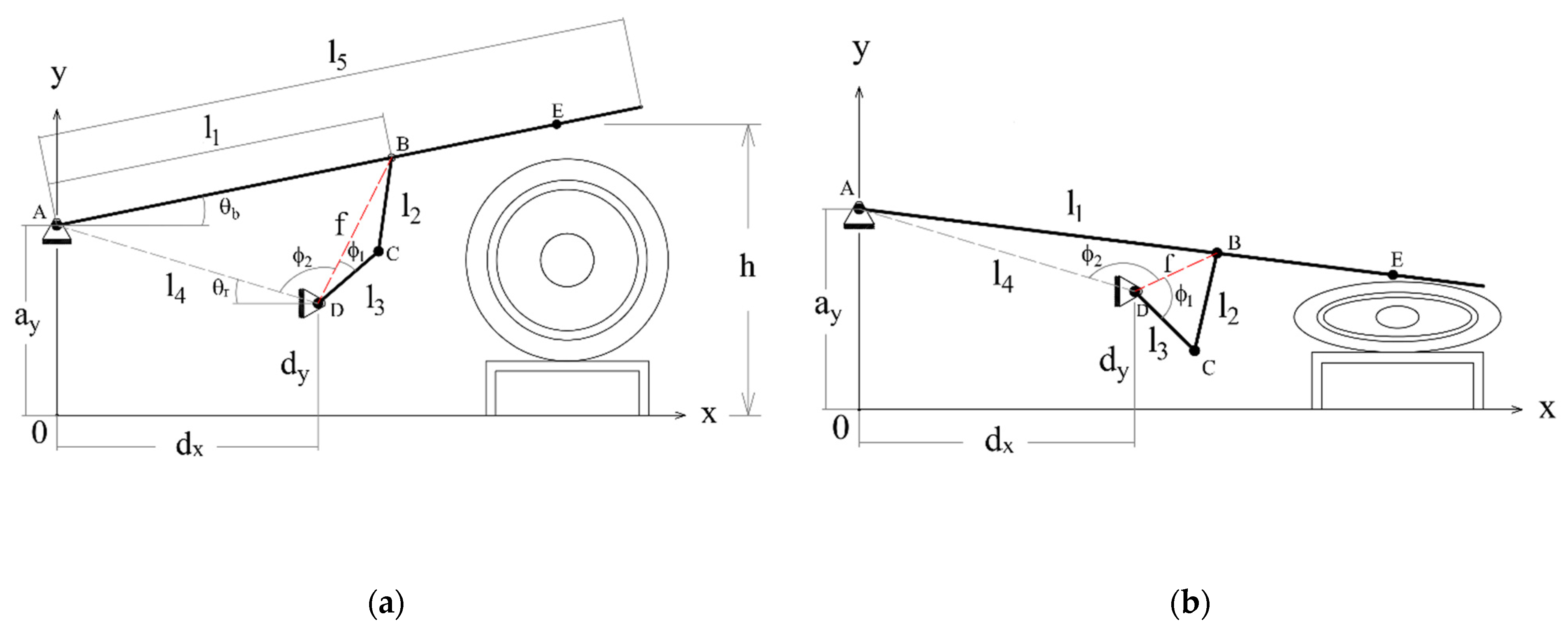
Figure 6a shows a diagram representing the mechanism in its initial position. In this case, the height h of the compression point E is at its greatest, and the respirator is not compressed at all. Figure 6b shows the mechanism at the end of the inspiration phase, when the height h is at its lowest and the respirator is more or less completely squeezed. The mechanism generates an adequate trajectory for point E that fits the pre-established respiration cycle.
2.2.3. Operation
The desired volume delivered to the patient will first be established and, from this, the parameters and of the cycle will be determined. After also inputting the desired frequency, the software will create the desired breathing cycle curve and find the necessary rotation angle of the motor . There will also be an option to regulate all the other parameters of the cycle, such as the durations of every phase and sub-phase.
Two sensors will provide feedback to the machine in order to prevent accidents. A flowmeter will be installed at the tube between the silicone bag and the face mask. By mathematically integrating the flow, the volume delivered to the patient’s lungs can be found, the cycle can be modified to ensure the adequate volume ranges are respected.
Furthermore, a pressure sensor will also be included to ensure that the values are not lower than the PEEP and not higher than the maximum threshold.
An emergency stop button will be installed in a prominent place to prevent any accidents.
It is not possible to use a completely automatic respirator with a conscious patient since their breathing reflexes and diaphragm contractions will conflict with the programmed breathing cycle. If a patient is conscious or still has breathing reflexes, they will need to be sedated completely to eliminate any conflict.
Some commercial mechanical respirators have sensors that can be used with conscious patients, detecting when they grasp for air and only then triggering the start of a new cycle only to help them. However, in the present design, this characteristic has been left for future improved versions.
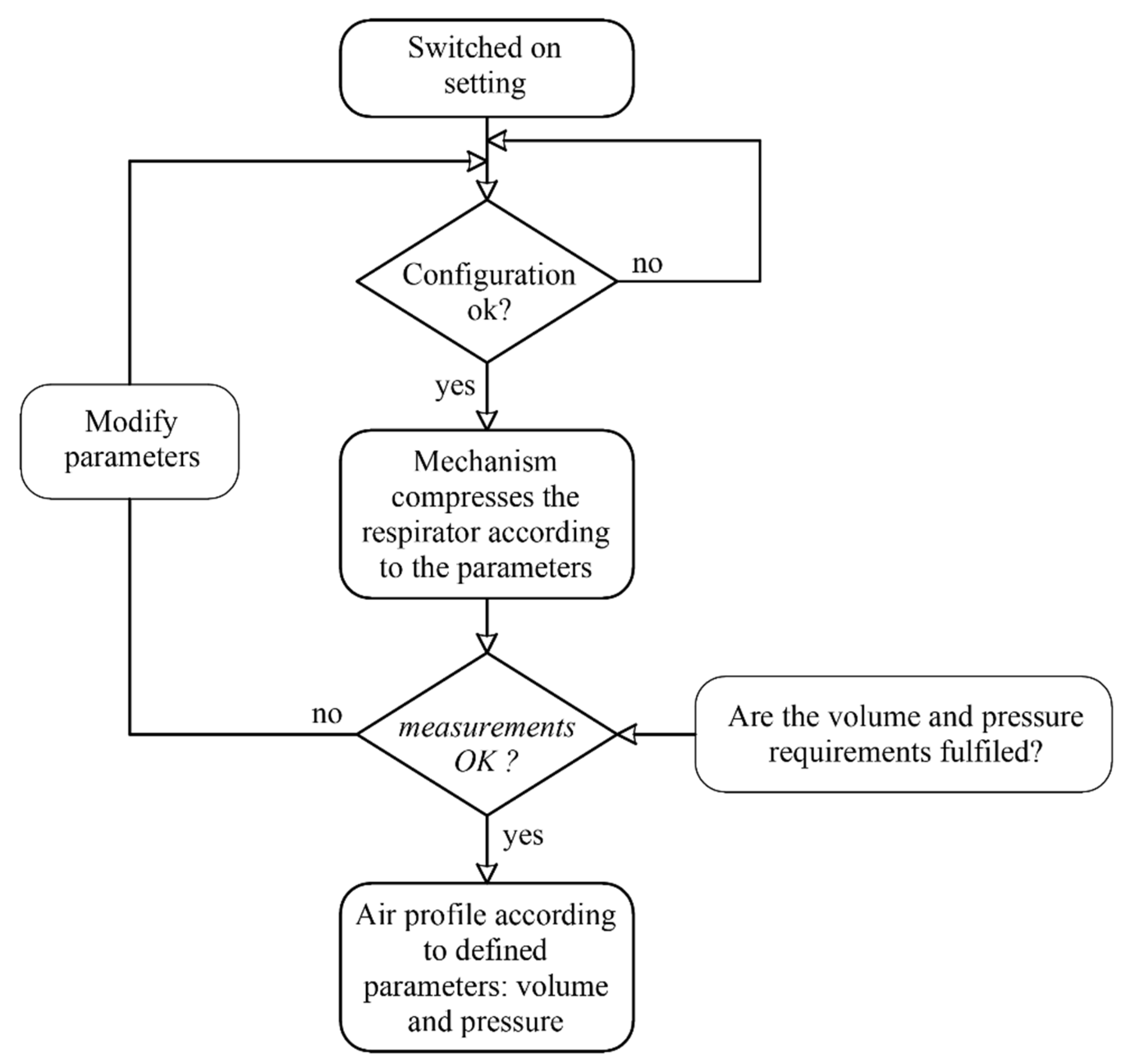
Figure 7 shows the flow diagram of the control. The system controls the rotation angle of the motor. Therefore, when the device is switched on, the motor will rotate until reaching a limit switch, with which the initial reference angle will be established. The control system collects the data of the flowmeter and the pressure sensor during the cycle, enabling the monitoring of the breathing cycle.
2.3. Design Details
This section will present the detail design of the mechanical and electrical aspects of the automation system.
2.3.1. Mechanism
The mechanism is responsible for operating the manual respirator, thus substituting a human operator. This mechanism consists of a four-bar linkage operated by a motor that moves a lever that compresses the respirator. Figure 8a shows the detail design of all the internal components, while Figure 8b shows the housing of the mechanism, with the respirator’s protective housing open. Suitable values for all the parametric dimensions of the model presented at 2.2.2 have been found in order to achieve a smooth operation.
From the detail design of the mechanism, the drawings of each part of the assembly can be created and be used for the materialization phase. The design will be modular for greater ease in assembly and maintenance, and all the materials will comply with sanitary regulations.
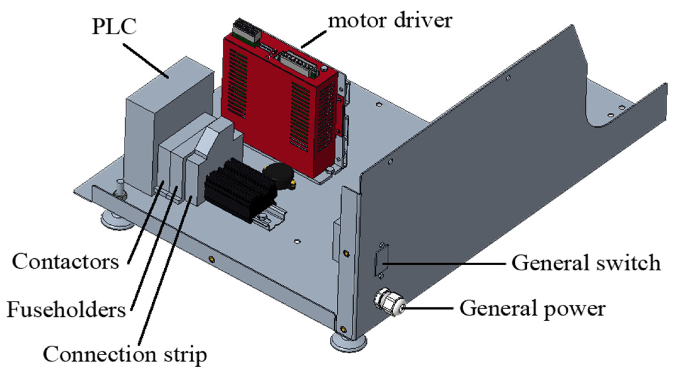
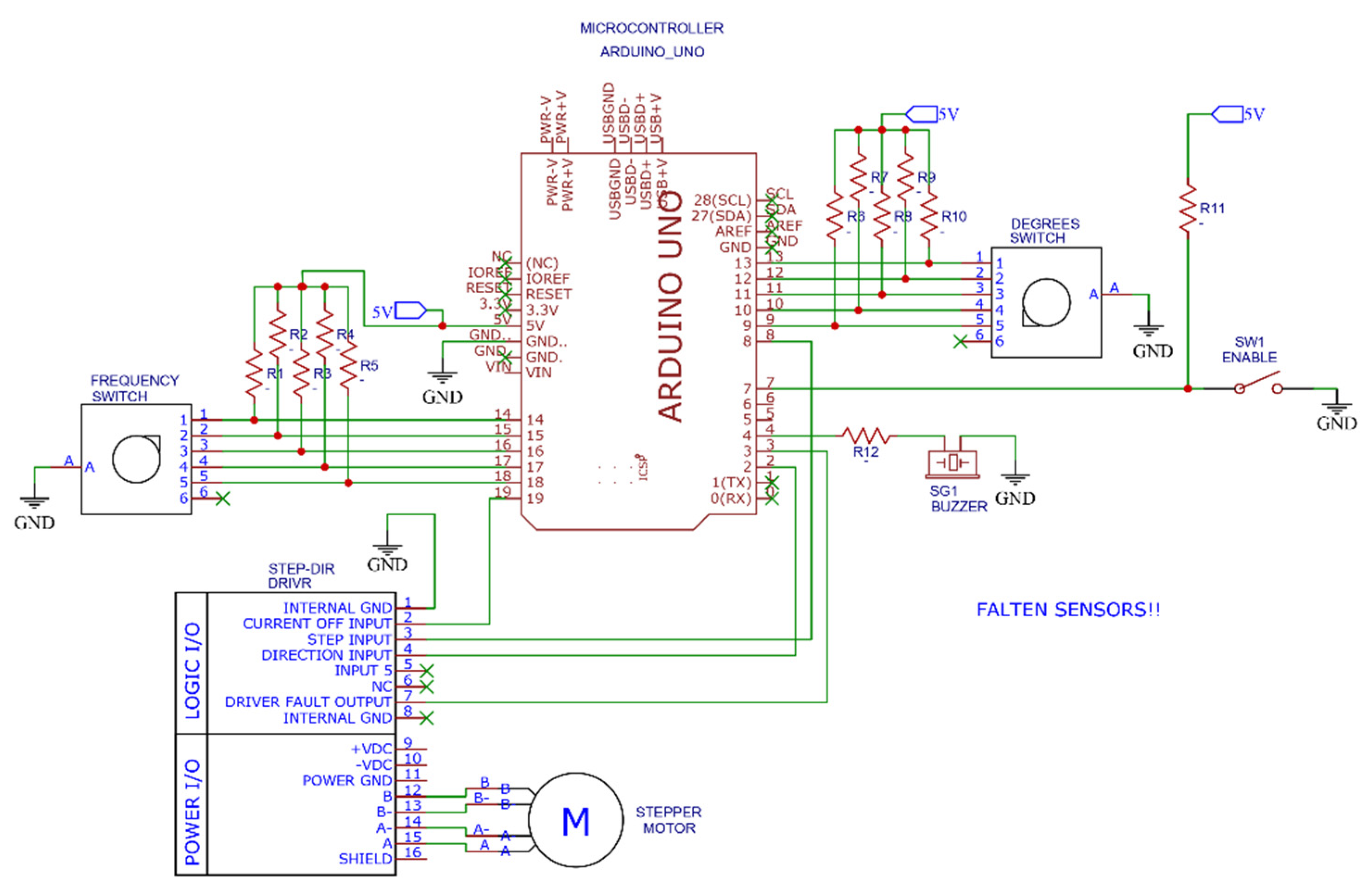
2.3.2. Electronic Circuit
The motor is governed by commercial, electronic control components. The parameters of the breathing cycle can be modified via a touchscreen mounted to the housing. Figure 9 shows the disposition of the control components, and Figure 10 shows the scheme of the electronic circuit.
All the electronic components are readily available worldwide and low cost (See Table 1). The machine’s code was implemented with open-source software such as IDE Arduino.
2.4. Materialization
The housing of the device is made of sheet metal of AISI-304L (1.4301) stainless steel, with 2 mm thickness. The outline of each structural part is first obtained via laser cut and then bent and welded. The parts are then pickled and polished to remove all irregularities and leave a smooth superficial finish.
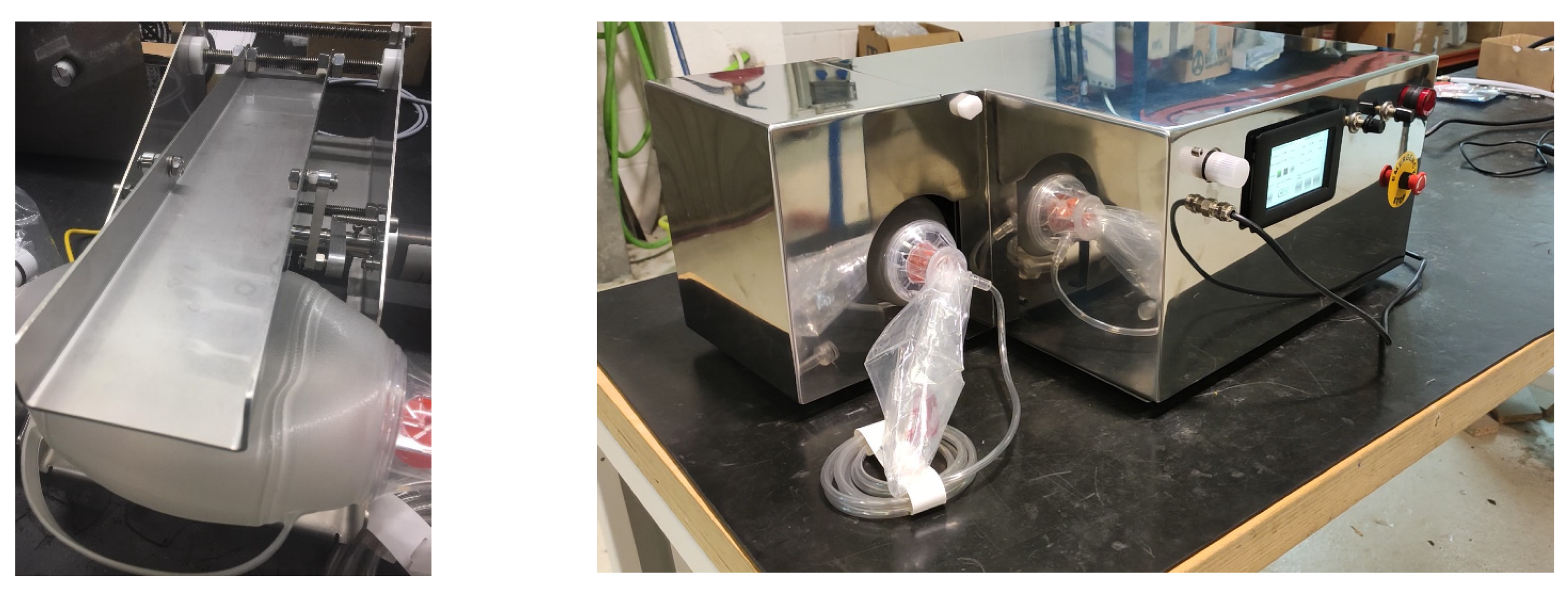
The lever and supports of the compression mechanism are made of the same bent stainless steel, while most of the other mobile elements are obtained via CNC machining. All the parts must undergo dimensional control according to the ISO-9001:2015 quality standard. Figure 11) shows the respirator without housing so that the mechanism can be seen, while Figure 11) shows the complete system with the housing, mechanism, electronics, and manual respirator.
The device can undergo sterilization processes with ozone or UV light.
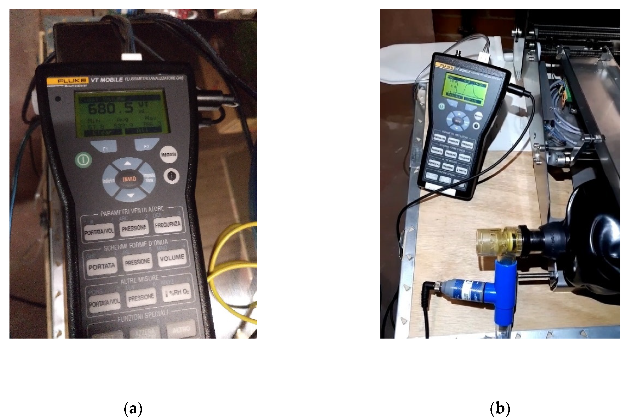
Tests
The gas flow analyzer FLUKE VT MOBILE has been used to test the reliability of the flow and pressure levels. The following magnitudes have been measured with this tool: bidirectional flow rate, volume, vacuum, pressure, and oxygen concentration. Figure 12a shows the volume measurements, while Figure 12b shows the pressure measurements.
3. Results
The following graphs show the results obtained for different configurations. Figure 13a shows the temporal evolution of the motor angle during a breathing cycle, while Figure 13b shows the temporal evolution of the motor angular velocity, both for a frequency of 15 cycles/min.
In the same vein, Figure 14a,b show the same results but with a frequency of 10 cycles per minute.
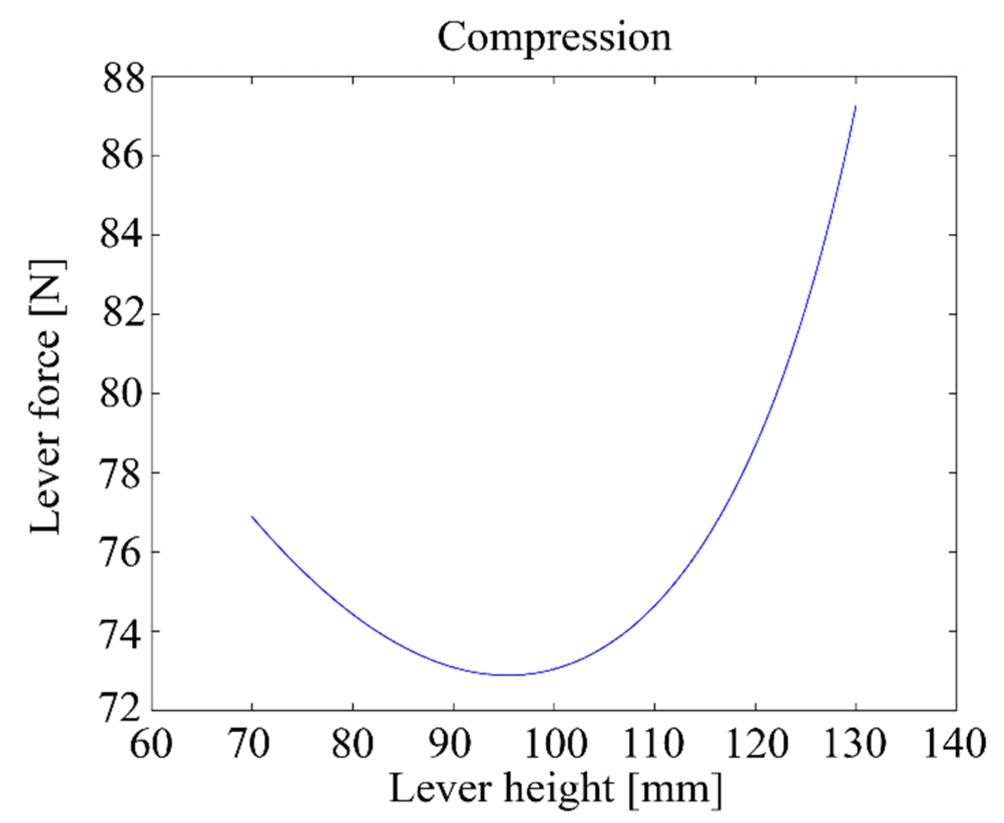
Figure 15 shows the relationship between the height h of the lever and the maximum compression force when the motor delivers a 5 Nm torque.
Table 2 shows the ranges of operation of the designed machine, which the machine complies with.
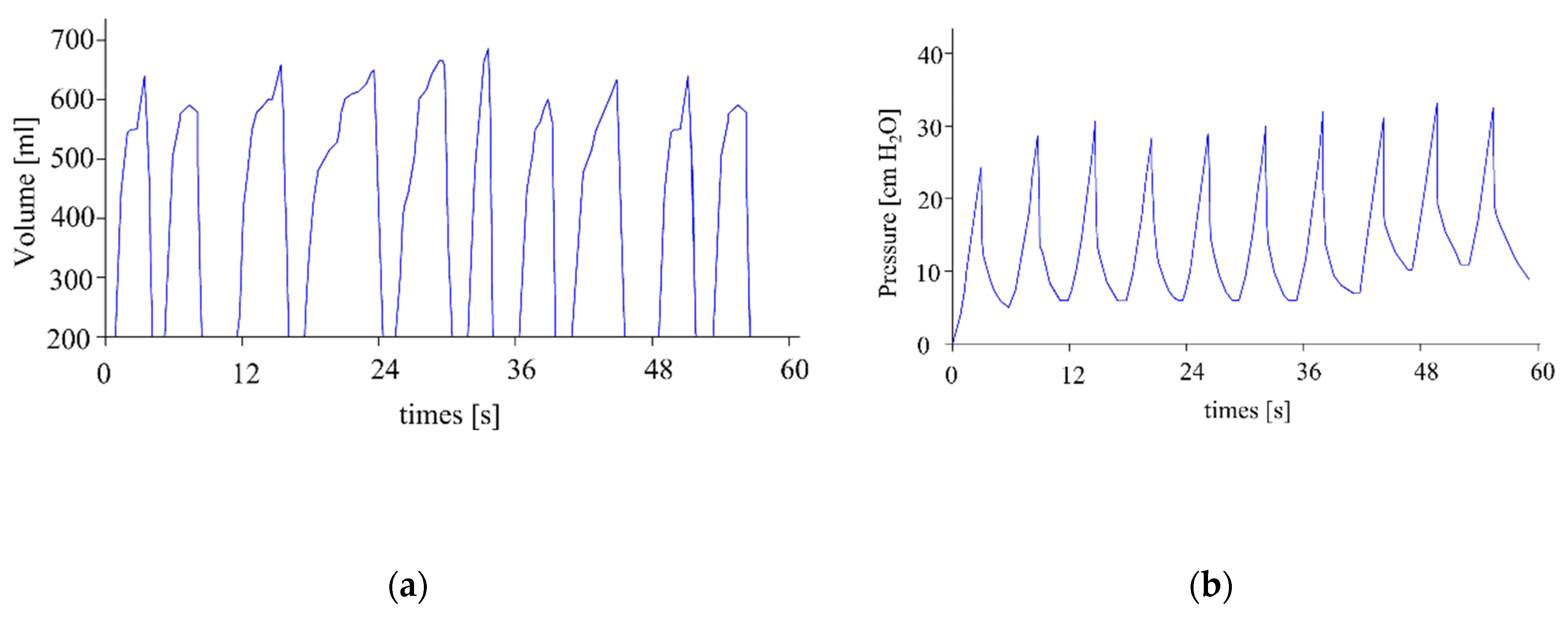
Figure 16a shows the experimental measurements of volume, while Figure 16b shows the experimental measurements of pressure. Both results are for a frequency of 10 cycles/minute, a PEEP of 10 cm H2O, a threshold alarm maximum pressure of 1 cm H2O, and a threshold alarm maximum pressure of 42 cm H2O. Both measurements show that the machine operates within the recommended ranges.
Tests were performed on the prototype to simulate the working conditions of a commercial respirator. The pressure and flow sensors were tested, and an alarm was calibrated to notify when the thresholds of maximum volume, maximum pressure and minimum pressure were reached. To simulate a rise in pressure, the exit tube of the respirator was blocked progressively; while to control the volume delivered in a practical way, a balloon was attached to the mask of the respirator.
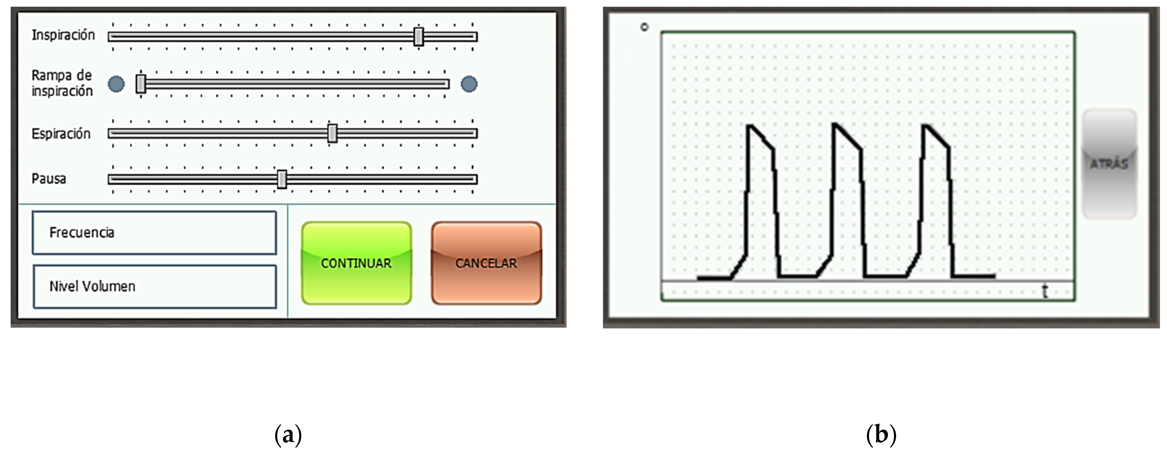
Figure 17a shows the menu with the parameters of the respiration cycle, each of which can be modified. Each slider governs a different parameter. In descending order: % of the cycle devoted to the inspiration phase, % of the inspiration phase devoted to the ramp subphase, % of the cycle devoted to the expiration phase, % of the cycle devoted to the pause phase, breathing frequency in cycles per minute, and total volume delivered to the patient in milliliters. Figure 17b touchscreen of the device with the readings of the rotation sensor of the motor in real time. Units: angle [°] per time [s].
4. Discussion
The designed device aims to automate the use of manual resuscitators of the type AMBU Spur II. Therefore, the designed system will share some of its characteristics, such as the uncontrolled expulsion of expiration gases into the atmosphere, the protection against overpressure with a safety valve, and a lack of fine-tuning minute details of the respiration cycle.
However, with this device, a medical staffer can be freed from constant work on the manual respirator, allowing them to attend several patients simultaneously [28]. The pressures and volumes provided to the patient in each cycle can be displayed graphically, allowing for easy monitoring.
The device complies with all the regulations. The cost of the prototype has been of approximately 1200 USD, while with appropriate adjustments, the cost of the final product can be reduced to 800 USD. Considering the system features protection against overpressure and warning alarms, its cost is considerably lower than most commercial respirators [8].
The mechanism is simple and its control electronics can be governed with intuitive menus displayed on a touchscreen. The design is replicable and cheap, making it a suitable alternative for developing countries.
5. Conclusions
The present COVID-19 pandemic has generated an unprecedented high number of patients with respiratory problems, which in turn has created a general shortage of mechanical ventilators. For this reason, in this article, the design of a mechanism to automate an AMBU Spur II manual resuscitator has been described. The device consists of a four-bar linkage mechanism driven by an electric motor that compresses the respirator in a very controlled manner at about 15 cycles per minute, and that can be controlled via a touchscreen.
First, all the characteristics of the breathing cycle have been established, and then, the corresponding degree of compression of the respirator has been determined. After the compression vs. time curve of the cycle has been determined, an algorithm will calculate the rotation angle of the motor needed to accomplish the cycle. The device also features sensors to monitor the pressure and volume of the delivered air in order to prevent injuries while also ensuring a minimum PEEP pressure.
The mechanism has been successfully materialized and tested, thus fulfilling the original objective: solving the shortage of mechanical respirators and freeing medical staff from having to devote all their time to a single patient, while operating a manual respirator.
The control electronics use low-cost, readily available commercial components, and have been programmed with open source software. The design uses common materials and manufacturing techniques, so, while it has been fabricated in a Western European country, its production has also been replicated in developing countries such as Ecuador.
Author Contributions
Conceptualization, C.D.-M. and E.B.-R.; methodology, E.B.-R. and M.A.-C.; software, A.d.l.F.-M. and M.A.-C.; validation, M.A.-C., C.D.-M. and E.B.-R.; formal analysis, C.D.-M., E.B.-R., A.d.l.F.-M. and M.A.-C.; investigation, C.D.-M., E.B.-R., A.d.l.F.-M. and M.A.-C.; writing—original draft preparation, M.A.-C. and A.d.l.F.-M.; writing—review and editing, C.D.-M., E.B.-R., A.d.l.F.-M. and M.A.-C.; visualization, M.A.-C.; supervision, C.D.-M. and E.B.-R.; project administration, C.D.-M. and E.B.-R.; funding acquisition, C.D.-M. and E.B.-R. All authors have read and agreed to the published version of the manuscript.
Funding
This research was funded by Centre de Cooperació per al Desenvolupament de la UPC (CCD) and Universidad Tecnológica Indoamérica.
Institutional Review Board Statement
Not applicable.
Informed Consent Statement
Not applicable.
Data Availability Statement
The data presented in this study are available in https://bit.ly/39LJWgO.
Acknowledgments
Clàudia Cabré, Bartomeu Costa, Ana Fusté, Andreu Punsola, Adrià Sánchez, Alexandra Vega, Universitat Politècnica de Catalunya, Universidad Tecnológica Indoamérica, and Secretaría de Educación Superior, Ciencia, Tecnología e Innovación SENESCYT.
Conflicts of Interest
The authors declare no conflict of interest.
References
- Güler, H.; Ata, F. Design and Implementation of Training Mechanical Ventilator Set for Clinicians and Students. Procedia-Soc. Behav. Sci. 2013, 83, 493–496. [Google Scholar] [CrossRef] [Green Version]
- Darwood, A.; McCanny, J.; Kwasnicki, R.; Martin, B.; Jones, P. The design and evaluation of a novel low-cost portable ventilator. Anaesthesia 2019, 74, 1406–1415. [Google Scholar] [CrossRef]
- Pham, T.; Brochard, L.J.; Slutsky, A.S. Mechanical Ventilation: State of the Art. Mayo Clin. Proc. 2017, 92, 1382–1400. [Google Scholar] [CrossRef] [PubMed] [Green Version]
- Guevara, C.; Penas, M.S. Surveillance Routing of COVID-19 Infection Spread Using an Intelligent Infectious Diseases Algorithm. IEEE Access 2020, 8, 201925–201936. [Google Scholar] [CrossRef]
- Mills, P.J.; Baptiste, J.; Preston, J.; Barnas, G.M. Manual resuscitators and spontaneous ventilation-An evaluation. Crit. Care Med. 1991, 19, 1425–1431. [Google Scholar] [CrossRef] [PubMed]
- Prado, C.D.; Guinsburg, R.; De Almeida, M.F.B.; Mascaretti, R.S.; Vale, L.A.; Haddad, L.B.; Rebello, C.M. Manual Ventilation and Sustained Lung Inflation in an Experimental Model: Influence of Equipment Type and Operator’s Training. PLOS ONE 2016, 11, e0148475. [Google Scholar] [CrossRef]
- Ortiz, T.D.A.; Junior, G.F.; Volpe, M.S.; Beraldo, M.D.A.; Amato, M.B.P.; Carvalho, C.R.R.; Tucci, M.R.; Forti, G. Evaluation of manual resuscitators used in ICUs in Brazil. J. Bras. de Pneumol. 2013, 39, 595–603. [Google Scholar] [CrossRef] [Green Version]
- Castro-Camus, E.; Ornik, J.; Mach, C.; Hernandez-Cardoso, G.; Savalia, B.; Taiber, J.; Ruiz-Marquez, A.; Kesper, K.; Konde, S.; Sommer, C.; et al. Simple Ventilators for Emergency Use Based on Bag-Valve Pressing Systems: Lessons Learned and Future Steps. Appl. Sci. 2020, 10, 7229. [Google Scholar] [CrossRef]
- Davies, J.D.; Costa, B.K.; Asciutto, A.J. Approaches to Manual Ventilation. Respir. Care 2014, 59, 810–824. [Google Scholar] [CrossRef] [PubMed] [Green Version]
- Halpern, P.; Dang, T.; Epstein, Y.; Dimitriades, D.V.S.; Koenig, K.L. Six Hours of Manual Ventilation with a Bag-Valve-Mask Device Is Feasible and Clinically Consistent. Crit. Care Med. 2019, 47, e222–e226. [Google Scholar] [CrossRef] [PubMed]
- Culbreth, R.E.; Gardenhire, D.S. Manual bag valve mask ventilation performance among respiratory therapists. Hear. Lung 2020. [Google Scholar] [CrossRef]
- Tusman, G.; Campos, M.; Gogniat, E. COVID-19: Cómo transformar un ventilador de no invasiva en un ventilador de críticos. Rev. Española Anestesiol. Reanim. 2020, 67, 367–373. [Google Scholar] [CrossRef]
- Roy, S.; Bunting, L.; Stahl, S.; Textor, D. Inline Positive End-Expiratory Pressure Valves: The Essential Component of Individualized Split Ventilator Circuits. Crit. Care Explor. 2020, 2, e0198. [Google Scholar] [CrossRef] [PubMed]
- Petsiuk, A.; Tanikella, N.G.; Dertinger, S.; Pringle, A.; Oberloier, S.; Pearce, J.M. Partially RepRapable automated open source bag valve mask-based ventilator. HardwareX 2020, 8, e00131. [Google Scholar] [CrossRef] [PubMed]
- Gino, B.; Wang, Z.; D’Entremont, P.; Renouf, T.S.; Dubrowski, A. Automated Inflating Resuscitator (AIR): Design and Development of a 3D-Printed Ventilator Prototype and Corresponding Simulation Scenario Based on the Management of a Critical COVID-19 Patient. Cureus 2020, 12, e9134. [Google Scholar] [CrossRef]
- Fang, Z.; Li, A.I.; Wang, H.; Zhang, R.; Mai, X.; Pan, T. AmbuBox: A Fast-Deployable Low-Cost Ventilator for COVID-19 Emergent Care. SLAS Technol. Transl. Life Sci. Innov. 2020, 25, 573–584. [Google Scholar] [CrossRef]
- Garmendia, O.; Rodríguez-Lazaro, M.A.; Otero, J.; Phan, P.; Stoyanova, A.; Dinh-Xuan, A.T.; Gozal, D.; Navajas, D.; Montserrat, J.M.; Farré, R. Low-cost, easy-to-build noninvasive pressure support ventilator for under-resourced regions: Open source hardware description, performance and feasibility testing. Eur. Respir. J. 2020, 55, 2000846. [Google Scholar] [CrossRef] [Green Version]
- Vasan, A.; Weekes, R.; Connacher, W.; Sieker, J.; Stambaugh, M.; Suresh, P.; Lee, D.E.; Mazzei, W.; Schlaepfer, E.; Vallejos, T.; et al. MADVent: A low-cost ventilator for patients with COVID-19. Med. Devices Sens. 2020, 3, 1–14. [Google Scholar] [CrossRef]
- Acho, L.; Vargas, A.N.; Pujol-Vázquez, G. Low-Cost, Open-Source Mechanical Ventilator with Pulmonary Monitoring for COVID-19 Patients. Actuators 2020, 9, 84. [Google Scholar] [CrossRef]
- OxyGEN: OxyGEN Project. Available online: https://www.oxygen.protofy.xyz/ (accessed on 5 January 2020).
- Fernández, F.J.V.; Segovia, J.S.; Bravo, I.M.; Ramos, C.G.; Castilla, D.R.; López, J.G.; Márquez, J.M.A. ResUHUrge: A Low Cost and Fully Functional Ventilator Indicated for Application in COVID-19 Patients. Sensors 2020, 20, 6774. [Google Scholar] [CrossRef] [PubMed]
- Leitat: Leitat. Available online: https://covid-leitat.org/en/ventilator/ (accessed on 1 May 2020).
- MIT: MIT Emergency Ventilator. Available online: https://emergency-vent.mit.edu/ (accessed on 1 May 2020).
- Kakkar, K.; Gupta, B. Is the use of automated artificial manual breathing unit resuscitators justified during a pandemic mechanical ventilator crisis? Acute Crit. Care 2020, 35, 220–222. [Google Scholar] [CrossRef] [PubMed]
- Redondo, L.C. Manual de Ventilación Mecánica; Formación Alcalá: Alcalá la Real, Spain, 2008. [Google Scholar]
- Rodríguez, A.E. Guía Esencial de Metodología en Ventilación Mecánica no Invasiva/Essential Guide of Methodology in Non-Invasive Mechanical Ventilation; Editorial Médica Panamericana: Madrid, Spain, 2010. [Google Scholar]
- López-Herce, J. Carrillo, Ángel Ventilación mecánica: Indicaciones, modalidades y programación y controles. Anales de Pediatría Continuada 2008, 6, 321–329. [Google Scholar] [CrossRef]
- Bourrianne, P.; Chidzik, S.; Cohen, D.; Elmer, P.; Hallowell, T.; Kilbaugh, T.J.; Lange, D.; Leifer, A.M.; Marlow, D.R.; Meyers, P.D.; et al. Inexpensive multi-patient respiratory monitoring system for helmet ventilation during COVID-19 pandemic. medRxiv 2020. [Google Scholar] [CrossRef]
Figure 1.
Conceptual flowchart of the design process.

Figure 2.
Conceptual design.

Figure 3.
Compressor lever height vs. time at 15 cycles per minute.

Figure 4.
Conceptual design of the automation system of a manual respirator. (a) Mechanism based on a four-bar linkage; (b) Ambu Spur II manual respirator.
Figure 4.
Conceptual design of the automation system of a manual respirator. (a) Mechanism based on a four-bar linkage; (b) Ambu Spur II manual respirator.

Figure 5.
(a) Conceptual diagram of the mechanism, (b) geometry of the detail design with the diagram superimposed.
Figure 5.
(a) Conceptual diagram of the mechanism, (b) geometry of the detail design with the diagram superimposed.

Figure 6.
Conceptual diagram of the mechanism with some intermediate variables added; (a) initial position; (b) final position.
Figure 6.
Conceptual diagram of the mechanism with some intermediate variables added; (a) initial position; (b) final position.

Figure 7.
Flowchart control.

Figure 8.
Detail design of the automation mechanism; (a) internal four-bar mechanism; (b) housing (opened).
Figure 8.
Detail design of the automation mechanism; (a) internal four-bar mechanism; (b) housing (opened).

Figure 9.
Electronic design and their disposition inside the device.

Figure 10.
Scheme of the electronic control system.

Figure 11.
(a) respirator without the protective housing; and (b) complete system with the housing.

Figure 12.
Measurements; (a) volume; and (b) pressure.

Figure 13.
Parameters of the motor for 15 cycles per minute; (a) rotation angle; (b) angular velocity.
Figure 13.
Parameters of the motor for 15 cycles per minute; (a) rotation angle; (b) angular velocity.

Figure 14.
Parameters of the motor for 10 cycles per minute; (a) rotation angle; (b) angular velocity.
Figure 14.
Parameters of the motor for 10 cycles per minute; (a) rotation angle; (b) angular velocity.

Figure 15.
Lever compression force vs. lever height with a 5 Nm motor torque.

Figure 16.
Measures of (a) volume and (b) pressure.

Figure 17.
Touchscreen of the device (a) menu with the parameters of the respiration cycle; (b) motor position.
Figure 17.
Touchscreen of the device (a) menu with the parameters of the respiration cycle; (b) motor position.


Table 1.
Bill of materials.
| Quantity | Description | Cost € |
|---|---|---|
| 2 | Cooper Bussmann, 10 A Cartridge Fuse, 10 × 38 mm, Speed F | 73.6 |
| 2 | Phoenix Contact RIF-0-RPT-24DC/1, SPNO, 24V dc, DIN rail | 13.4 |
| 20 | Phoenix Contact, FBS 2-6 Jumper Bar for Modular Terminal Block | 8.80 |
| 1 | Panel Mount Blue LED Pilot Light Complete With Test Circuit, 22 mm Cutout, IP65 | 6.11 |
| 1 | Schurter 1 Pole Non Fused Isolator Switch—10 A Maximum Current | 23.3 |
| 1 | 4D Systems 4DCAPE-43T TFT LCD Colour Display/Touch Screen, 4.3in, 480 × 272 pixels | 88.6 |
| 1 | Phoenix Contact DIN Rail UPS, 24V dc Output—Buffer Module, input 100 → 350 V·dc, 85 → 264 V·ac | 210 |
| 1 | APEM Panel Mount Emergency Button—Twist to Reset, 16 mm Cutout Diameter, 2NC, Mushroom Head | 18.3 |
| 4 | Nu-Tech Engineering Adjustable Feet A300/001 M8 40 mm, 40 mm Dia. Stainless Steel, Stainless Steel 450 kg Static Load | 76.2 |
| 20 | Phoenix Contact, STTBS 2.5 BU, 500 V Spring Cage, Spring Clamp Termination, Black | 14.5 |
| 1 | Development kit interface USB to UART | 18.9 |
| 1 | ABB 2 Pole Type AC Residual Current Circuit Breaker, 25A FH200, 30 mA | 84.3 |
| 100 | RS PRO Insulated Crimp Bootlace Ferrule, 8 mm Pin Length, 1.7 mm Pin Diameter, 18 AWG·1 mm2 Wire Size, Red | 3.94 |
| 1 | Phoenix Contact Battery For Use With Energy Storage Device, 2866417, 130 × 52 × 110 mm | 108 |
| 2 | RS PRO Reed Switch Cylindrical 200V, NO, 500 mA | 19.1 |
| 100 | Molex, SL Female Crimp Terminal Contact 24AWG 16-02-0069 | 4.90 |
| 2 | RS PRO Cylindrical Proximity Switch Magnet, 11 × 28 mm | 9.06 |
| 1 | Omron EMI Filter for use with VZ B0P7, VZ B1P5—169mm Length, 20 A, 200 V ac, 1.5 kW | 41.9 |
| 2 | Mersen 32A Rail Mount Fuse Holder for 10 × 38 mm Fuse, 1P, 690V ac/dc | 9.62 |
| 1 | PLC Arduino ARDBOX 20 I/Os | 141 |
| 20 | Phoenix Contact, ST 2.5 RD, 800 V Feed Through Terminal Block, Spring Clamp Termination | 17.2 |
| 100 | RS PRO Insulated Crimp Bootlace Ferrule, 8 mm Pin Length, 1.1 mm Pin Diameter, 0.34 mm2 Wire Size, Pink | 8.25 |
| 1 | Mean Well MDR Switch Mode DIN Rail Panel Mount Power Supply with Overvoltage and Short Circuit Protection, 1 output 15V dc 670 mA 10 W | 13.9 |
| 10 | Molex 50-57-9005, SL female connector | 3.50 |
| 2 | RS PRO 1 Gang Rotary Wirewound Potentiometer with a 6 mm Dia. Shaft—5 kΩ, ±10%, 1W Power Rating, Linear, Panel Mount | 9.42 |
| TOTAL | 1028.14 € | |
Table 2.
Recommended operation ranges of a respirator.
| Operation Parameters | Recommended Ranges |
|---|---|
| Frequency | 5–30 cycles/min |
| Minimum pressure | 0–20 cm H2O |
| Maximum pressure | 30–60 cm H2O |
| Minimum volume | 200 mL |
| Maximum volume | 1000 mL |
Publisher’s Note: MDPI stays neutral with regard to jurisdictional claims in published maps and institutional affiliations. |
© 2021 by the authors. Licensee MDPI, Basel, Switzerland. This article is an open access article distributed under the terms and conditions of the Creative Commons Attribution (CC BY) license (http://creativecommons.org/licenses/by/4.0/).
Share and Cite
MDPI and ACS Style
Domènech-Mestres, C.; Blanco-Romero, E.; de la Fuente-Morató, A.; Ayala-Chauvin, M. Design for the Automation of an AMBU Spur II Manual Respirator. Machines 2021, 9, 45. https://0-doi-org.brum.beds.ac.uk/10.3390/machines9020045
AMA Style
Domènech-Mestres C, Blanco-Romero E, de la Fuente-Morató A, Ayala-Chauvin M. Design for the Automation of an AMBU Spur II Manual Respirator. Machines. 2021; 9(2):45. https://0-doi-org.brum.beds.ac.uk/10.3390/machines9020045
Chicago/Turabian StyleDomènech-Mestres, Carles, Elena Blanco-Romero, Albert de la Fuente-Morató, and Manuel Ayala-Chauvin. 2021. "Design for the Automation of an AMBU Spur II Manual Respirator" Machines 9, no. 2: 45. https://0-doi-org.brum.beds.ac.uk/10.3390/machines9020045
Note that from the first issue of 2016, this journal uses article numbers instead of page numbers. See further details here.