Article

On the Suspension Design of Paquitop, a Novel Service Robot for Home Assistance Applications

Department of Mechanical and Aerospace Engineering, Politecnico di Torino, 10129 Torino, Italy
*
Author to whom correspondence should be addressed.
Submission received: 27 January 2021 / Revised: 17 February 2021 / Accepted: 24 February 2021 / Published: 2 March 2021

Abstract

:
The general and constant ageing of the world population that has been observed in the last decade has led robotics researchers community to focus its aims to answer the ever-growing demand for health care, housing, care-giving, and social security. Among others, the researchers at Politecnico di Torino are developing a novel platform to enhance the performance offered by present-day issues, and to assess many others which were not even taken into consideration before they have been highlighted by the pandemic emergency currently in progress. This situation, in fact, made dramatically clear how important it is to have reliable non-human operators whom one can trust when the life of elderly or weak patients is endangered by the simple presence of other people. The platform, named Paquitop, features an innovative architecture conceived for omni-directional planar motion. The machine is designed for domestic, unstructured, and variously populated environments. Therefore, the mobile robot should be able to avoid or pass over small obstacles, passing through the capability to achieve specific person tracking tasks, and arriving to the need of operating with an high dynamic performance. Given its purpose, this work addresses the design of the suspension system which enables the platform to ensure a steady floor contact and adequate stability in every using condition. Different configurations of such system are then presented and compared through use-case simulations.

1. Introduction

The ageing of the population and the increasing attention to automatized caregiving are pushing research towards the development of autonomous machines, tailored to meet the need of assisting weak or non-self-sufficient subjects [1]. The current pandemic emergency caused by the Covid-19, has highlighted the need of freeing many activities from the presence of human operators, especially in hospital environments or geriatric wards and hospices, where patients are endangered by their closeness to other people [2]. Although human staff cannot be replaced entirely (e.g., for complex operations and companionship), properly conceived and instrumented robots can be entrusted with other duties. Blood pressure, temperature, and oxygen saturation measurements, patient monitoring, triage activities, delivery of lightweight medical products and documents or simply remote presence are some examples of tasks that could be easily assessed without the presence of humans. Moreover, autonomous machines can accomplish these easy tasks enabling a better redistribution of the precious human resource on those fundamental duties where operators cannot be replaced by robots.
Pursuing this objective automatically implies a variety of technical challenges that go far beyond a careful motion planning and smart control of the robotic system, even if significant advances were made in this sense [3]: on-line path planning [4], innovative use of sensors [5], and development of localization strategies [6] are examples of the fields that caught the attention of the research community. Alongside with such aspects, also the mechanical design plays a role of paramount importance [7,8], together with the development of dedicated models able to simulate mechanical system [9,10]. In the past, a class of robots was exploited more than others for domestic use, namely, those owning two fixed driven wheels, also known as differential-drive robots. Among others, DeSantis proposed path-tracking control for this class [11]; later on Chung et al. inquired their position kinematics and control [12]; in 2010 Chwa proposed a control law based on a recursive linearization of the robot model [13]; recently Bruzzone et al. developed an innovative actuation system merging the peculiarities of legged, wheeled, and tracked robots [14]. The reasons for such success lie in their simplicity of use and cost effectiveness. Nonetheless, their limited manoeuvrability makes them less attractive for applications where a superior orientation ability is required. The research about over-actuated robots mostly involved the problems linked to the non- or quasi-holonomic constraints they involve [15,16], and the difficulties aroused by the control of the over-abundant set of actuators [17]. As a matter of fact, most devices which involve actuation redundancy make use of omni-wheels, whose correct functioning strictly depends on the evenness and materials of the ground, and on the absence of wheels slip. Additionally, their use in unstructured environments can be extremely complex for autonomous motions, especially in presence of obstacles and surfaces with different friction characteristic since in such case the behaviour of the wheels can be very far from the expected kinematic behaviour. These are the premises which led the researchers at Politecnico di Torino to develop an innovative platform, named Paquitop [18], as the base modular frame for indoor robotized assistance applications. Therefore, the platform must exhibit strong manoeuvrability and be built with a modular approach to fulfil a variety of monitoring and basic assistance tasks in different scenarios. A robot with full in-plane mobility is therefore well desirable. The platform, whose conceptual design is shown in Figure 1, is an over actuated robot suspended on four wheels. Two of them are driven steering wheels, while two are standard off-centred passive castor wheels. Although almost all the kinematic architectures for mobile robots have already been somehow investigated, the main strength of the proposed solution lies in the mechanical design of its actuation system: on the one hand, such scheme provides a redundant set of actuated constraints with respect to the degrees of freedom, on the other hand, it allows taking advantage of omni-directional mobility without the disadvantages characterizing omnidirectional wheels (which poorly fit the use in domestic environments). Due to its particular workspace, the robot should be shaped on a human scale, in order to access all the spaces which are usually lived in by people.
Therefore, a non-axisymmetric footprint is preferable to a symmetric one so that the robot is able to offer, when needed, a reduced profile to pass through confined spaces. It is worth noticing that the presence of four contact points with the ground implies the need of using an adequate suspension system, necessary to assess the soil unevenness and to enhance its capability to overpass reasonably low obstacles without compromising its whole balance. In fact, most indoor robots do not make use of suspensions, while outdoor rovers provided with suspensions often adopt active systems [19,20]. To contain costs and complexity of the project, a passive suspension approach is preferable. In this paper, different designs of the suspension systems are discussed and compared through use-case simulations. The aim of the research is to provide design guidelines for the future construction phase of the prototype by evaluating the dynamic performance of the mobile robot adopting different configurations of suspensions.

2. Platform Mobility

In a study conducted by the authors [18] about the kinematic of this architecture, it was shown that the mobility of the robot can be classified into four different classes of steering configurations. As more deeply investigated in that work, the platform holonomic forward kinematics is ruled by:
x ˙ = [ r w 2 ( ϑ ˙ w r c γ + δ w r + ϑ ˙ w l c γ + δ w l ) r w 2 ( ϑ ˙ w r s γ + δ w r + ϑ ˙ w l s γ + δ w l ) r w 2 a ( ϑ ˙ w r c δ w r ϑ ˙ w l c δ w l ) ]
where x ˙ = [ x ˙ c y ˙ c γ ˙ ] T , with x c and y c coordinates of the origin of the chassis reference frame { c } and γ rotation angle of { c } with respect to the fixed reference frame { 0 } . The angles ϑ and δ respectively are the rotation about the axle and the steering angle of the generic wheel which will be identified through the symbol , an acronym that identifies each one of the wheels: w r ( w l ) for the right (left) driven wheel and c f ( c b ) for the front (back) castor wheel. Besides, the short-end notation c ε = cos ε and s ε = sin ε is adopted, where ε is a generic angle. The robot structure is described through a set of local reference frames defined in Figure 2.
The platform is provided with two independent actuated steering wheels to achieve omnidirectional mobility in the plane, but due to this actuation redundancy the joint variables ϑ and δ need to be assumed considering the constraint:
ϑ ˙ w r s δ w r ϑ ˙ w l s δ w l = 0
With a critical analysis of Equations (1) and (2), it is possible to define the aforementioned classes of steering configurations, briefly described hereby and illustrated in Table 1.
  • Configuration I: adopting different steering angles δ w r δ w l , the robot exploits all its degrees of actuation to achieve a general motion in the plane.
  • Configuration II: when the axes of the two driven wheels are parallel, but not 0 or π / 2 , the robot is able to translate while rotations are inhibited. Assuming δ w r = δ w l 0 , π / 2 Equation (2) imposes that the angular velocities ϑ ˙ w r and ϑ ˙ w l are equal. In this configuration, the platform is able to translate while maintaining a fixed direction of observation.
  • Configuration III: when the steering angles of the driven wheel are zero, the mobility of the robot corresponds to the well-known scenario of a differential actuation. Equation (2) is fulfilled whatever angular velocity is provided. Consequently, the robot is able to exhibit an angular velocity but loses the possibility of owning a y -directed velocity in { c } .
  • Configuration IV: when the steering angles are equal to π / 2 , the configuration of the robot is very similar to Configuration II with driven axes parallel and not coincident. However, the platform exhibits improvedstatic and dynamic performance which enables high accelerations of the robot. Besides, a small variation to just one of the two wheels, or opposed small angles around π / 2 , would also allow the robot to approach curved trajectories without relevant modifications to its ability to absorb higher accelerations in that direction.
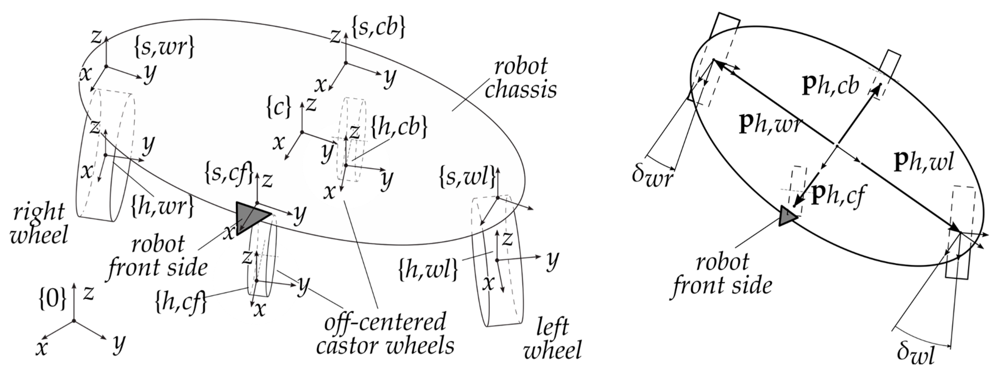
The mechanical structure proposed for the platform imparts advantages related mainly to manoeuvrability, but it introduces some disadvantages. For example, a proper mechanical design of the wheel suspension must be foreseen to guarantee a steady floor contact and stability in every using condition, even when the robot is passing over obstacles or is performing curved trajectories. Towards the comparison of different designs of the suspensions system, a dynamic model is presented and analysed. In the next section, this model is fitted to the peculiarities of the different suspension designs.

2.1. Kinematics

In the rest of the paper, the following short-end notation is used: R i j is the rotation matrix from the reference frame (r.f. in the following) { i } to r.f. { j } ; if the rotation takes place along one the r.f. axes x , y , z it is indicated with R e , ε with e axis and ε amount of rotation; the origin of the r.f.’s are indicated with the vector p i j which are the coordinates of the origin of the frame { j } expressed with respect to { i } ; for the sake of simplicity, the r.f. is omitted when the vector is expressed in { 0 } .
It is possible to identify the pose of the robot in the workspace through the r.f. { c } , attached to the chassis. The position of the origin of the r.f. { c } is defined by the position vector p c = [ x c y c z c ] T , while its orientation is described by three rotations around the axes x , y and z of the absolute frame { 0 } , i.e., R c = R z , γ R y , β R x , α . The robot pose is fully described in the Cartesian space by six kinematic parameters which are collected in the vector q = [ x c y c z c α β γ ] T .
The local r.f. { s , ~ } are solid with the chassis and the origin is coincident to the connection point of each suspension with the chassis. Thus, the origin position is expressed by four constant position vectors p c s , ~ . The z coordinates of such points with respect to { 0 } are directly relatable to the deformation of each spring-damper system as shown later.
The location of the centre of mass of the chassis can be described similarly, through the vector p c c m . For the sake of simplicity, and given the machine geometry, the position of the centre of mass has been assumed aligned to the z axis of r.f. { c } . The geometric parameters relevant to the definition of the model are shown in Figure 3. The resulting vectors with respect to { c } are:
p c s , w r = [ 0 a 0 ] T p c s , w l = [ 0 a 0 ] T p c s , c f = [ b 0 0 ] T p c s , c b = [ b 0 0 ] T p c c m = [ 0 0 p c m , z ] T
Given the vectors in Equation (3), the absolute positions of the relevant chassis points are:
p s , = p c + R c   p c s , p c m = p c + R c   p c c m
while the velocities are:
p ˙ s , = p ˙ c + ω c × R c   p c s , p ˙ c m = p ˙ c + ω c × R c   p c c m
where:
ω c = [ α ˙ c β c γ β ˙ s γ α ˙ c β s γ + β ˙ c γ α ˙ s β + γ ˙ ]

2.2. Simplified Dynamics Model

The dynamics of the robot is worked out through a Lagrangian approach starting from the kinematics described in the previous section in analogy with reference [18]. Since the mass of each wheel is negligible with respect to that born by the chassis and the field of application of Paquitop (a service robot in a domestic environment) implies a limited maximum velocity, with a consequent negligible vertical dynamics of the wheels, it is possible to disregard the contribution provided by the non-suspended masses, i.e., the four wheels. Under these assumptions, the robot dynamics can be approximately described by the Lagrangian of the chassis, given by:
L = T U
where T is the kinetic energy of the chassis and U is the potential energy of the conservative forces acting on it. In particular, the kinetic energy T can be expressed by:
T = 1 2 p ˙ c m T m p ˙ c m + 1 2 ω c T R c J c R c T ω c
where m is the robot mass and J c is the inertia tensor of the chassis expressed in terms of the r.f. { c } .
The potential energy U of the conservative forces shall collect the contributions of the four springs, one for each wheel, which suspend the robot chassis and the gravity potential associated with the chassis mass. Under the assumption of weightless perfectly rigid wheels, the forces exerted by the springs on the chassis are evaluated as:
F c k , = [ 0 0 k ( l 0 , l ) ] T
where k is the stiffness and l 0 , , l respectively are the free length and the actual length of the spring ~ . Referring to Figure 4, the free length of the spring has been set so that:
l 0 , = z c , 0 r + f 0 , k
where z c , 0 is the desired free height of the chassis from the contact plane, r is the wheel radius and f 0 , is the preload of the spring. Obviously, the sum of the four pre-load forces must equate the weight of the robot in static condition:
i = f 0 , i = m g
The actual length l , according to Figure 2, is given by:
l = d r d v , ~
where d and d v , ~ are the distances of the points p s , and p v , from the plane x - y of r.f. { 0 } . The distance d that can be estimated as it follows:
d w r = z c c α c β a t α d c f = z c c α c β b t β c α d w l = z c c α c β + a t α d c f = z c c α c β + b t β c α
with t α = tan α . The distances in Equation (13) clearly represent an approximation of the actual values of distance among the suspension attachment points and the ground, especially for the castor wheels for whom the presence of the off-centre length was disregarded. Nonetheless, it is worth remarking that in normal working conditions, the out-of-plane motions of the chassis should be kept as small as possible. In this case, (13) represents a reasonable approximation. The distances d v , ~ can be estimated similarly as it follows:
d v , ~ = z v , ~ c α c β
where z v , ~ is the z coordinate of the vector p v , with respect to {0}. Once the four spring forces have been defined, the potential energy turns:
U = 1 2 i = k ( l 0 , l ) 2 + m g ( z c z c , 0 )
where g is the gravity acceleration module. Similarly to what done for the elastic forces F c k , , a set of actions coming from the suspension’s dampers can be defined in the r.f. { c } :
F c c , = [ 0 0 c l ˙ ] T
with l ˙ the time derivative of the spring length defined by Equation (12). As known then, the dynamics equations of the mobile robot can be expressed by:
d d t ( L q ˙ ) L q = [ R c i =   F c c , R c i =   p c s , × F c c , ]

2.3. Castor Wheel’s Offset Effect

Equation (17) has been evaluated neglecting the off-centre length of the castor wheels. Some changes need to be done to evaluate the effect of the moving contact point between passive wheels and the ground, due to the castor wheel off-centre length. In this sense, the dynamic model here defined represents a further improvement of the model proposed in reference [21] where the effect of the moving contact point was neglected.
The vertical forces generated by the contact between castor wheels and the ground are applied to the contact points p v , which do not lie on the z axis of {h, ~ } reference frame, defined by the origin in p h , and orientation R c h , ~ = R c s , ~   R z , δ ~ . This leads to the generation of torque applied to the chassis along with the projection of y axis of {h, ~ } on the x y plane of { c } . The torques applied to the chassis by the castor wheels turn:
M c r c , ~ = R c s , c ~ ( p s , c ~ w , × F s , c ~ r c , )
where F s , c ~ r c , = [ 0 0 k ( l 0 , l ) c l ˙ ] T and p s , c ~ w , = R s , c ~ h , ~   [ b c 0 0 ] T .

3. Functional Suspension Design

The aim of the section is to introduce three different functional designs for the wheel suspension. As previously mentioned, the presence of suspension is fundamental to guarantee a steady floor contact and stability in every use condition. To identify the best solution for a future prototype of the platform, different configurations of the suspension system are compared. Such simulations do not consider as a possibility the use of extremely soft tyres for the negative effects they would have on the robot efficiency. In the following sections, the dynamic model previously presented is adapted to better describe the behaviour of the different suspension designs. At last, the model parameters are assumed for the next simulation phase.

3.1. Two Arms Suspensions: Design: 2A

The dynamics model presented in Section 3 is worked out assuming that each wheel suspension is independent. Such a configuration can be achieved in different ways. In this section, this suspension configuration is supposed to be built using two independent arms. Such brackets are connected to the wheels through an element which enables the steering motion, and to the chassis by a central revolute joint. Figure 5b shows a functional scheme for the actuated wheels. The same architecture can then be drawn for the castor wheels suspensions.
The connection between the wheel and the central revolute joint is realized through a single bracket for the sake of construction simplicity. Due to the kinematics offered by such scheme, the wheel will not purely move along the vertical axis, for the hypothesis of pure translation decays. Nonetheless, considering a range of motion of about ± 20   mm from the initial condition, and an arm length of 250   mm , the maximum rotation of the wheel is limited at ± 2.3 ° from the initial condition which is acceptable.
At this point of the design of the platform, it has not been defined yet where the spring-damper elements will be installed. Thus, in contrast to the illustration in Figure 5b, the suspension systems are supposed to be placed right above the wheels, as assumed in the model previously defined in Section 3. For these reasons, the dynamic Equation (17) describe the behaviour of this configuration without modifications.

3.2. Suspension Design: 2AR, Configuration 2A with a Generic Anti-Rool Device

In order to reduce the roll rotation of the platform, an anti-roll system can be implemented. Different technologies and architectures of such systems have been proposed in the past [22], particularly in automotive applications. Regardless of which type of anti-roll systems is adopted, the presence of such a system will be modelled as a generic torsional spring system acting on the roll axis of the platform. In this way, it is possible to evaluate the effectiveness of implementing this system over the robotic platform assuming equivalent torsional stiffness and it will be up to the designer to adapt the equivalent parameter to the specific technology chosen. The model presented in Section 3 needs to be modified to consider the presence of the anti-roll device. Let k a , r o l l be the stiffness of the torsional spring, then the device applies a torque to the chassis, given by:
M c a , r o l l , ~ = [ k a , r o l l α   0 0 ] T

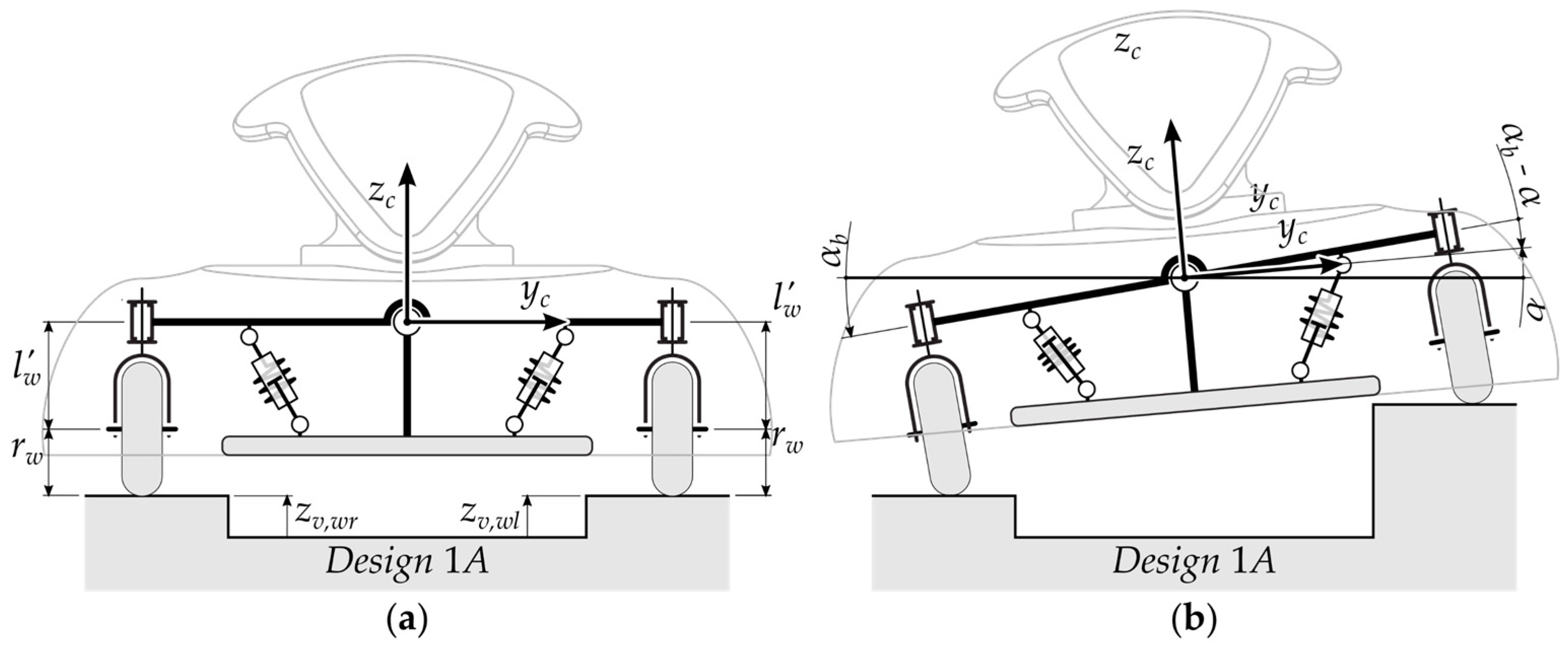
3.3. One Arm Suspensions: Design 1A

The last functional design proposed in this piece of research is characterized by a one-arm suspension for the actuated wheels, schematically represented in Figure 5a, and a two independent arms suspension for the passive wheels. As opposed to the other designs, this architecture introduces a kinematic constraint between the z coordinates of the contact points (actuated wheels-ground) and the coordinate z c of the chassis.
For this configuration, a different dynamic model is presented. The main parameters are depicted in Figure 6a. The presence of one-arm suspension introduces a kinematic constraint between the coordinates z v , ~ of the actuated wheels and the coordinate z c of the chassis. Under the hypothesis of small rotations, this constraint can be expressed by:
z c = z v , w r + z v , w l 2 + r w + l w
The spring-damper devices represented in Figure 6b can be modelled using an equivalent torsional spring-damper system characterized by the torsional stiffness k r o l l and the torsional damping coefficient c r o l l . This equivalent system works on the relative rotation between the suspension arm and the chassis over the roll axis. The rotation of the suspension arm is described by the auxiliary variable α b which can be related to the coordinates z v , ~ of the actuated wheels by the relation:
α b = z v , w l     z v , w r 2 a
Thus, the torque applied by the equivalent torsional spring-damping system can be expressed by:
M c r o l l = [ k r o l l ( α b α ) + c r o l l   ( α ˙ b α ˙ ) 0 0 ] T
Concerning the model presented in Section 1, the kinetic energy T remains unchanged, while the potential energy U varies:
U = 1 2 k r o l l ( α b α ) 2 + 1 2 k ( l 0 , l ) 2 + m g ( z c z c , 0 )
where stands for the acronym which identifies the castor wheels c f and c b , where the suspensions system remains the same as before. The set of actions coming from the suspension dampers can be defined in the r.f. { c } :
F c c , = [ 0 0 c l ˙ ] T ;             M c c , r o l l = [ c r o l l ( α ˙ ) 0 0 ] T
where ~ stands for the acronym which identifies the castor wheels c f and c b . Thus, the dynamics equations of the mobile robot can be expressed by:
d d t ( L x ˙ ) L x = [ R c i = F c c , R c ( i = p c s , × F c c , + M c c , r o l l ) ]

3.4. Parameter Selection

The succeeding analyses have been performed supposing the inertial and geometrical parameters of the robot chassis and the parameters of the suspension are as it follows:
  • Robot geometry: at this point of the design process, the geometry of the chassis is not precisely defined yet. The dimensions used here are hypothesized accordingly to the need of allowing the platform to work in a human-sized environment. Due to that, it is chosen a = 0.25   m , b = 0.15   m which provides the robot with a footprint similar to that of a person. The chassis has been supposed elliptical. The whole robot body was approximated by the prism built on such footprint, with a total eight of h = 0.4   m .
  • Robot mass and inertia: the inertial properties of the robot were estimated supposing a homogeneous mass distribution within the elliptic prism. With a mass m = 15   kg , the principal inertia moments are: J x , x = 0.434   kgm 2 , J y , y = 0.284   kgm 2 , J z , z = 0.319   kgm 2 . Given the shape and the uniform mass distribution, the centre mass is elevated by h / 2 with respect to the origin of r.f. { c } .
  • Robot suspension parameters: the analyses have been performed under the hypotheses of symmetrical left-right and front-back suspensions; therefore, it was considered:
    k w r = k w l = k w k c f = k c b = k c c w r = c w l = c w c c f = c c b = c c f 0 , w r = f 0 , w l = f 0 , w f 0 , c f = f 0 , c b = f 0 , c
  • Adopting the dynamic optimization method proposed in [21], the suspension parameters for the design 2A are evaluated to optimize the pitch roll dynamics, as suggested by the non-axisymmetric aspect of the robot which will produce remarkable out of plane rotations. In this way, the parameters of the suspensions turn to be k w = 2.698 · 10 3   N / m ; k c = 7.494 · 10 3   N / m ; c w = 200.2   Ns / m ; c c = 514.3   Ns / m . Concerning the other configurations of the suspensions system, parameters of the same order of magnitude of the respective parameters for the 2A design were selected: k a , r o l l = 100   N / rad ; k r o l l = 500   N / rad ; c r o l l = 50   Ns / rad . For the succeeding analyses, the suspensions were set up so that f 0 , c = 0 and f 0 , w = 1 2 m g . Such assumption is made because the passive wheels have been introduced as a simple solution for providing stability to a two-wheel platform without the need of complex self-balancing strategies. In this perspective, the additional contact points with the ground, provided by the passive wheels, become active only when the platform starts pitching, but no loads are applied on the castor wheels at zero velocity. The parameters are recapped in Table 2.

4. Simulation Results

In this section, the three architectures of the suspension system are tested through dynamics simulations of actual use cases implemented in the MatLab enviroment. The first steering configuration, identified in the first part of the paper as Configuration I, has been applied to the trajectories presented in Figure 7 and Figure 8. The two simulations were chosen to solicit the platform in different ways, simulating the loads caused by curved paths, Figure 7, and by the presence of obstacles laying on the ground, Figure 8.
In Case study 1 the robot reaches the cruise velocity of 1   m / s in the first straight section through a constant acceleration transient; similarly, a constant deceleration phase is used to stop the robot at the end of the path. During the curved sections, the linear velocity of the robot is planned to be constant at 1   m / s . The curved sections of the motion planning used for Case study 1 of Figure 7a are characterized by interesting kinematics properties. Adopting a fourth order Bezier polynomial with a particular choice of the control points, it is possible to avoid discontinuous steps of acceleration when approaching a curve. As an example, a qualitative representation of accelerations and velocities during a curved section is presented in Figure 7b.
It should be noticed that the module of the velocity is constant, while the module of acceleration varies continuously from 0   m / s 2 to a maximum value and then goes back to zero at the end of the curved section. Adopting this method, a smooth motion planning with zero-acceleration at curve approach is acquired. The trajectory in Case study 2 is straightway and characterized by the presence of an obstacle laying on the ground. In this case, the velocity of the robot is constant at 1.0   m / s . The obstacle is a small step, height 10   mm , width 10   mm , inclined at 20° with respect to the trajectory normal.
The resulting motions were imposed on the non-linearized dynamic model of Paquitop expressed by Equation (17) and adapted to the three functional suspension designs to compare the resulting solicitation on the non-controlled degrees of freedom. Moreover, the suspensions are supposed to work only in compression field to model the presence of limit switches which do not enable elongations over the free length of the systems. Physically, such switches prevent the suspensions to work in elongation field and, consequently, no traction force can be produced (as it actually happens when a wheel loses contact with ground).

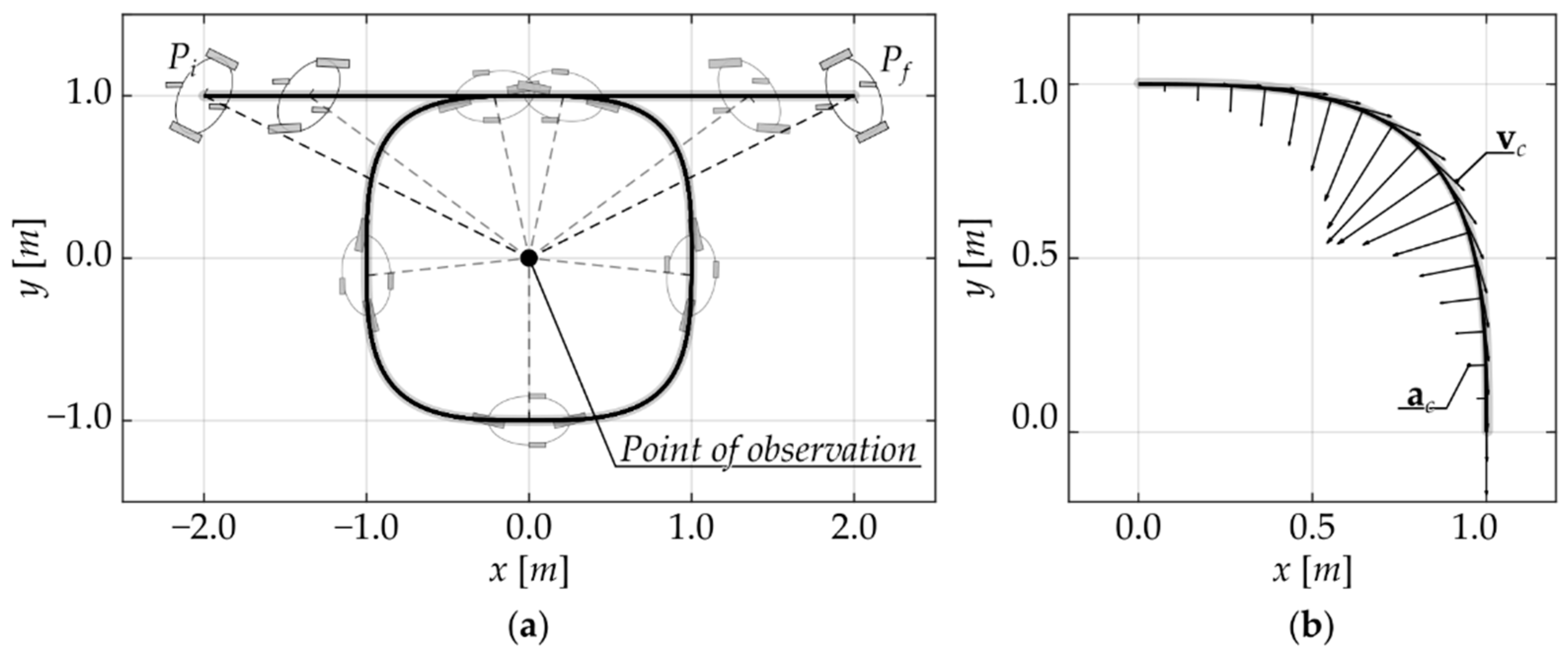
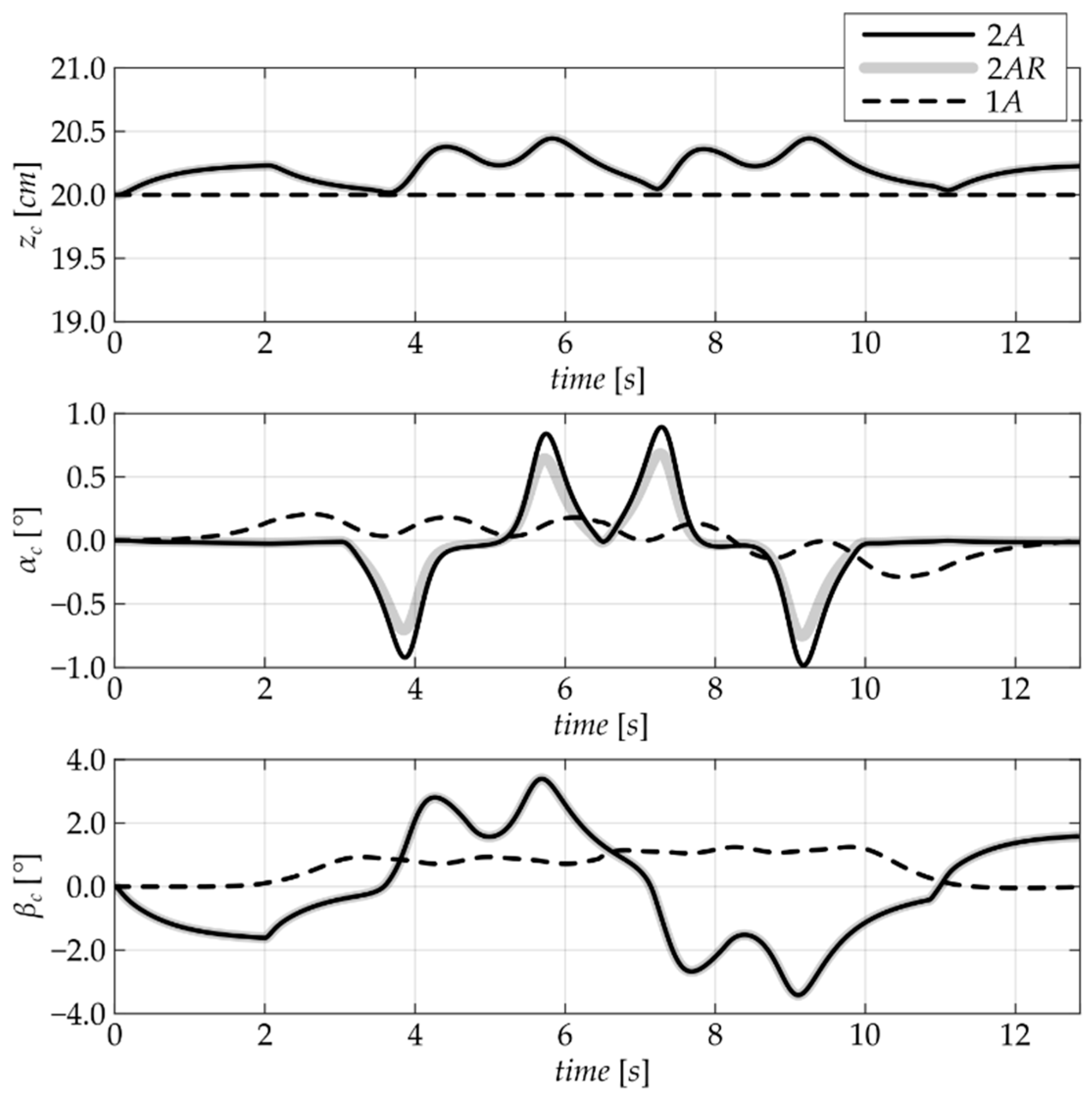
4.1. Case Study 1: The Curved Path

This case study involves steering Configuration I, namely the one where the robot exploits all of its degrees of actuation to achieve a general motion in the plane. In particular, the trajectory was run while keeping a constant line of sight with a point in the plane. This case represents an interesting use case since it exploits the actual peculiarities of the robot, provided by its degree of over-actuation. The dynamic simulation is built on the trajectory previously described, with a machine characterized by inertial and mass properties depicted in Section 3.4.
The test results are shown in Figure 9. The curves show that the design 1A results in maximum values of roll and pitch rotations that are 70.77 % and 63.22 % lower, respectively, compared to the 2A architecture, while no significant differences are revealed on the vertical axis. Furthermore, the improved dynamic performance is achieved with a simpler design of construction, which makes the one-arm configuration promising for the prototype architecture. Regarding the general order of magnitude of the response, the variation of the quantities is limited under 5   mm for the z c coordinate and under 5 ° for the pitch and roll angles. This fact underlines that the choice of the suspension parameters is coherent with the application and it makes the hypothesis of small variation acceptable. Concerning the differences between the 2A and the 2AR architectures, it should be noticed that the presence of the anti-roll device results in a 23.24 % lower α c absolute rotation, as expected.

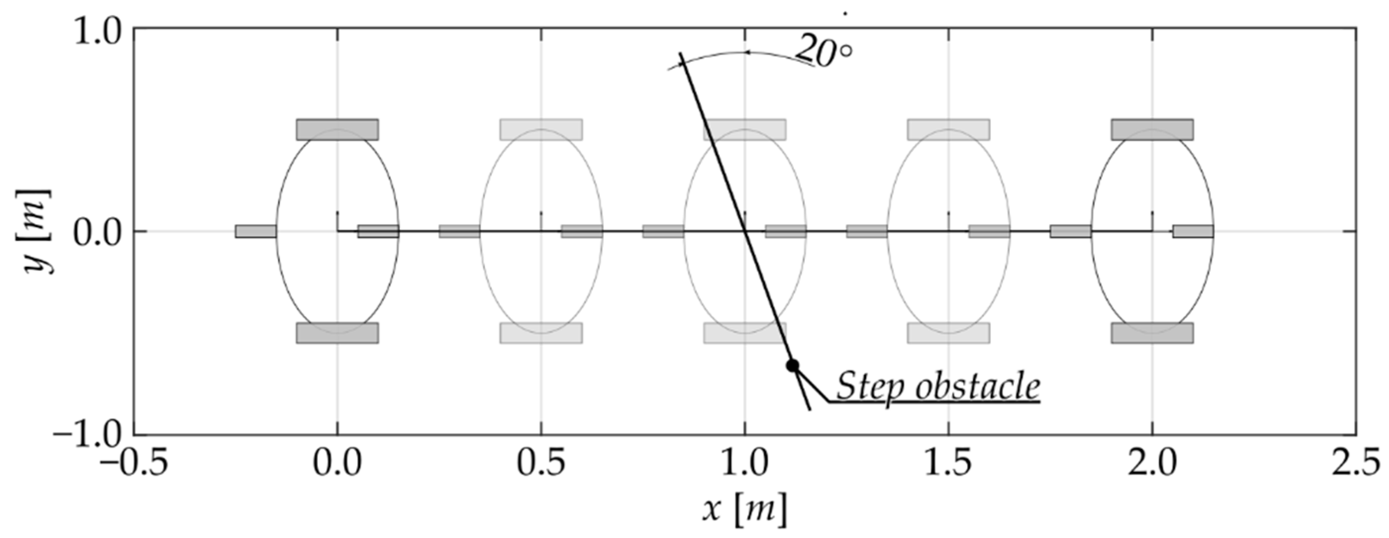
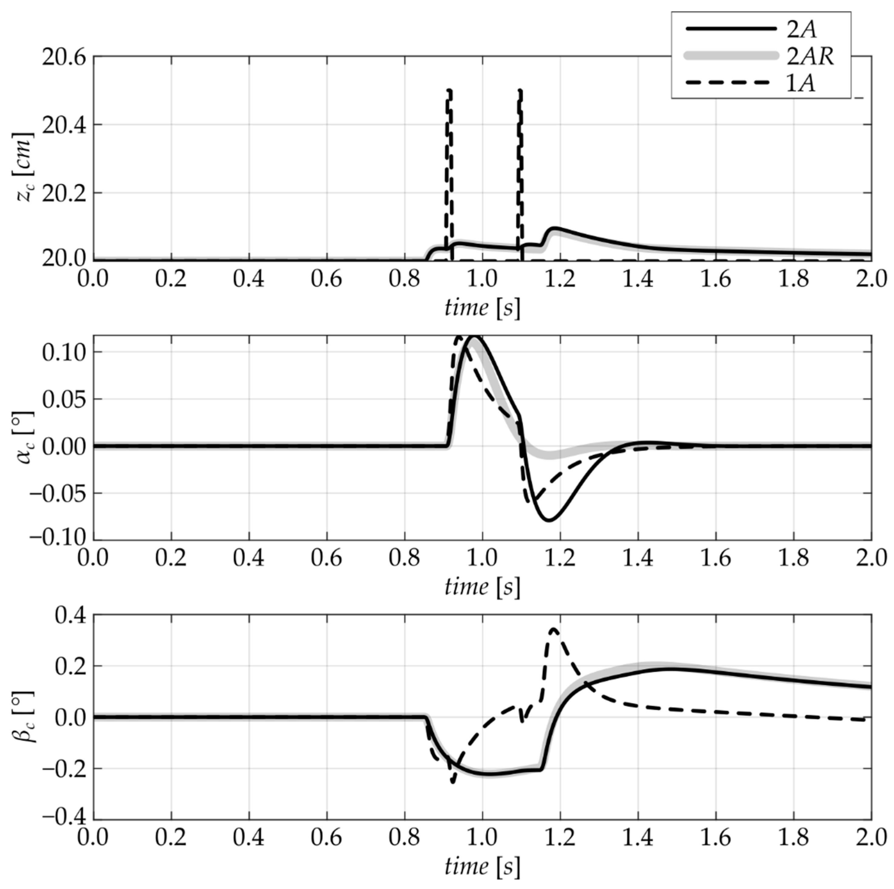
4.2. Case Study 2: Straight Path with an Obstacle

The second case aims at evaluating the robot behaviour while overpassing obstacles. In particular, a small step was considered, laying on the ground and tilted with respect to the trajectory of the platform. It is important to underline that the kinematic constraint introduced by the one-arm configuration (represented by Equation (20)) leads the platform to a high variation of the z c coordinate if both actuated wheels hit against the step simultaneously. This is a very uncommon situation in the field of application because the obstacles laying on the ground of a typical residence are randomly arranged. Therefore, an obstacle avoidance strategy can be implemented on the vehicle to ensure that the platform engages the step with a certain degree of rotation between the obstacle and the y axis of the platform. For this reason, the case study uses a tilted obstacle instead of a parallel one although it solicits also the pitch and roll degrees of freedom.
Figure 10 reports the test results for Case study 2. About the vertical motion of the platform, it is evident that, due to the presence of the kinematic constraint (20), the one-arm configuration does not filter enough the vertical disturbance introduced by the step. For this reason, the architectures 2A and 2AR show better behaviour at overpassing obstacles, with a maximum vertical displacement from the static equilibrium condition 80.74 % and 82.56 % lower, respectively, than the variation evaluated for design 1A. However, it should be underlined that due to the angle of inclination between the step and the trajectory of the robot, the vertical variation of the centre of the robot is a half of the height of the step, so a certain amount of filtration is achieved.

5. Conclusions

In this work, the authors investigated the effects of different architectures of the suspension system on the dynamic performance of the robotic platform Paquitop. The main objective of the project was that of providing a reliable architecture for omni-directional motions. The solution proposed by the authors addresses this with an over actuated architecture, which needs particular attention in the definition of the suspension parameters. In keeping with the kinematic capabilities of Paquitop, firstly a non-linear dynamics model is proposed to consider significant phenomena. This model is conceived to analyse the variation of the contact points between the passive wheels and the ground due to their off-centre length, the pre-load of the suspension and the fact that the suspension usually works only under compression. Secondly, this general model has been adapted to different architectures of the suspension system. These preliminary steps were used to perform two dynamic simulations of the robotic platform in typical use-case scenarios. The results reveal that the one-arm design for the suspension system is the most promising both for its simplicity of construction and the lower pitch and roll oscillations during curved trajectories, 70.77% and 63.22% respectively, compared to the 2A and 2AR architecture. Unfortunately, it is not optimal at overpassing obstacles, although, such a disadvantage can be addressed with a properly conceived obstacle-approach strategy which prevents the robot from engaging an obstacle with the two driven wheels simultaneously. Finally, it was shown that even if the dynamic performance is encouraging without an anti-roll system, its presence can significantly reduce the oscillations around the roll axis.

Author Contributions

Conceptualization, G.Q.; Methodology, L.T., A.B., P.C., L.C. and G.Q.; Formal Analysis, L.T., A.B., P.C., L.C. and G.Q.; Data Curation, L.T.; Writing—Original Draft Preparation, L.T.; Writing—Review & Editing, L.T., A.B., P.C., L.C. and G.Q.; Visualization, L.T.; Supervision, G.Q.; Project Administration, G.Q.; Funding Acquisition, G.Q. All authors have read and agreed to the published version of the manuscript.

Funding

This research received no external funding.

Institutional Review Board Statement

Not applicable.

Informed Consent Statement

Not applicable.

Data Availability Statement

Not applicable.

Conflicts of Interest

The authors declare no conflict of interest.

References

  1. Romero-Garcés, A.; Martínez-Cruz, J.; Inglés-Romero, J.F.; Vicente-Chicote, C.; Marfil, R.; Bandera, A. Measuring quality of service in a robotized comprehensive geriatric assessment scenario. Appl. Sci. 2020, 10, 6618. [Google Scholar]
  2. Yang, G.Z.; Nelson, B.J.; Murphy, R.R.; Choset, H.; Christensen, H.; Collins, S.H.; McNutt, M. Combating COVID-19—The role of robotics in managing public health and infectious diseases. Sci. Robot. 2020, 5589. [Google Scholar] [CrossRef] [Green Version]
  3. Rosolia, U.; Zhang, X.; Borrelli, F. Data-driven predictive control for autonomous systems. Annu. Rev. Control Robot. Auton. Syst. 2018, 1, 259–286. [Google Scholar] [CrossRef]
  4. Gia Luan, P.; Thinh, N.T. Real-time hybrid navigation system-based path planning and obstacle avoidance for mobile robots. Appl. Sci. 2020, 10, 3355. [Google Scholar] [CrossRef]
  5. Jung, J.W.; Park, J.S.; Kang, T.W.; Kang, J.G.; Kang, H.W. Mobile robot path planning using a laser range finder for environments with transparent obstacles. Appl. Sci. 2020, 10, 2799. [Google Scholar] [CrossRef] [Green Version]
  6. Aguiar, A.; Santos, F.; Sousa, A.J.; Santos, L. FAST-FUSION: An improved accuracy omnidirectional visual odometry system with sensor fusion and gpu optimization for embedded low cost hardware. Appl. Sci. 2019, 9, 5516. [Google Scholar] [CrossRef] [Green Version]
  7. Juel, W.K.; Haarslev, F.; Ram’ırez, E.R.; Marchetti, E.; Fischer, K.; Shaikh, D.; Manoonpong, P.; Hauch, C.; Bodenhagen, L.; Kruger, N. Smooth robot: Design for a novel modular welfare robot. J. Intell. Robot. Syst. 2020, 98, 19–37. [Google Scholar] [CrossRef]
  8. Ito, S.; Sugiura, S.; Masuda, Y.; Nohara, S.; Morita, R. Mechanism and control of a one-actuator mobile robot incorporating a torque limiter. J. Intell. Robot. Syst. 2020, 97, 431–448. [Google Scholar] [CrossRef]
  9. Rivera, Z.B.; De Simone, M.C.; Guida, D. Unmanned ground vehicle modelling in Gazebo/ROS-based environments. Machines 2019, 7, 42. [Google Scholar] [CrossRef] [Green Version]
  10. Vasiliev, A.; Dalyaev, I. Simulation Method for the Transport System of a Small-Sized Reconfigurable Mobile Robot. Machines 2021, 9, 8. [Google Scholar] [CrossRef]
  11. DeSantis, R.M. Modeling and path-tracking control of a mobile wheeled robot with a differential drive. Robotica 1995, 13, 401–410. [Google Scholar] [CrossRef]
  12. Chung, Y.; Park, C.; Harashima, F. A position control differential drive wheeled mobile robot. IEEE Trans. Ind. Electron. 2001, 48, 853–863. [Google Scholar] [CrossRef]
  13. Chwa, D. Tracking control of differential-drive wheeled mobile robots using a backstepping-like feed-back linearization. IEEE Trans. Syst. Man Cybern. Part A Syst. Hum. 2010, 40, 1285–1295. [Google Scholar] [CrossRef]
  14. Bruzzone, L.; Baggetta, M.; Nodehi, S.E.; Bilancia, P.; Fanghella, P. Functional Design of a Hybrid Leg-Wheel-Track Ground Mobile Robot. Machines 2021, 9, 10. [Google Scholar] [CrossRef]
  15. Korayem, M.H.; Ghariblu, H. Analysis of wheeled mobile flexible manipulator dynamic motions with maximum load carrying capacities. Robot. Auton. Syst. 2004, 48, 63–76. [Google Scholar] [CrossRef]
  16. White, G.D.; Bhatt, R.M.; Tang, C.P.; Krovi, V.N. Experimental evaluation of dynamic redundancy resolution in a nonholonomic wheeled mobile manipulator. IEEE/ASME Trans. Mechatron. 2009, 14, 349–357. [Google Scholar] [CrossRef]
  17. Dietrich, A.; Wimbock, T.; Albu-Schaffer, A.; Hirzinger, G. Reactive whole-body control: Dynamic mobile manipulation using a large number of actuated degrees of freedom. IEEE Robot. Autom. Mag. 2012, 19, 20–33. [Google Scholar] [CrossRef] [Green Version]
  18. Carbonari, L.; Botta, A.; Cavallone, P.; Quaglia, G. Functional design of a novel over-actuated mobile robotic platform for assistive tasks. In Proceedings of the International Conference on Robotics in Alpe-Adria Danube Region, Cham, Switzerland, 17–19 June 2020; pp. 380–389. [Google Scholar]
  19. Iagnemma, K.; Rzepniewski, A.; Dubowsky, S.; Schenker, P. Control of robotic vehicles with actively articulated suspensions in rough terrain. Auton. Robot. 2003, 14, 5–16. [Google Scholar] [CrossRef]
  20. Jiang, H.; Xu, G.; Zeng, W.; Gao, F.; Chong, K. Lateral stability of a mobile robot utilizing an active ad-justable suspension. Appl. Sci. 2019, 9, 4410. [Google Scholar] [CrossRef] [Green Version]
  21. Carbonari, L.; Botta, A.; Tagliavini, L.; Cavallone, P.; Quaglia, G. Dynamics characterization of paquitop, a novel platform for robotized domestic applications. In Proceedings of the IMECE International Mechanical Engineering Congress & Exposition, 16–19 November 2020. [Google Scholar]
  22. Tseng, H.E.; Hrovat, D. State of the art survey: Active and semi-active suspension control. Veh. Syst. Dyn. 2015, 53, 1034–1062. [Google Scholar] [CrossRef]
Figure 1. Preliminary conceptual design of the PAQUITOP robot.
Machines 09 00052 g001
Figure 2. Position of the bodies reference frames within the PAQUITOP kinematic structure.
Machines 09 00052 g002
Figure 3. Relevant geometrical parameters of the robot.
Machines 09 00052 g003
Figure 4. Spring force acting on the chassis body.
Machines 09 00052 g004
Figure 5. Suspensions configurations: (a) one-arm configuration (named 1A); (b) two-arms configurations (named 2A).
Machines 09 00052 g005
Figure 6. One arm suspension configuration: (a) Relevant geometrical parameters; (b) Definition of angular coordinates.
Machines 09 00052 g006
Figure 7. Use case simulation 1: curved path definition (a) qualitative representation of the accelerations and (b) velocities obtained in the curved sections
Machines 09 00052 g007
Figure 8. Use case simulation 2: straight path with a step obstacle.
Machines 09 00052 g008
Figure 9. Use case simulation 1: non-controlled degrees of freedom.
Machines 09 00052 g009
Figure 10. Use Case simulation 2: results.
Machines 09 00052 g010
Table 1. Possible steering configurations of the over-actuated mobile robot.
Configuration IConfiguration II
δ w r δ w l θ ˙ w r θ ˙ w l = s δ w l s δ w r
Machines 09 00052 i001
δ w r = δ w l 0 , π / 2
  θ ˙ w r = θ ˙ w l
Machines 09 00052 i002
Configuration IIIConfiguration IV
δ w r = δ w l = 0
Machines 09 00052 i003
δ w r = δ w l = π / 2
  θ ˙ w r = θ ˙ w l
Machines 09 00052 i004
Table 2. Robot parameters.
ParameterValueUnitsParameterValueUnits
a 0.250 m J x , x 0.434 kg   m 2
b 0.150 m J y , y 0.284 kg   m 2
h 0.400 m J z , z 0.319 kg   m 2
b c 0.015 m k w 2.698 · 10 3 N / m
r w 0.050 m k c 7.494 · 10 3 N / m
r c 0.040 m c w 200.2 Ns / m
p c m , z 0.200m c c 514.3 Ns / m
Publisher’s Note: MDPI stays neutral with regard to jurisdictional claims in published maps and institutional affiliations.

