
Feeling Machine for Process Monitoring of Components with Stock Allowance

Institute of Production Engineering and Machine Tools, Leibniz University Hannover, 30823 Garbsen, Germany
*
Author to whom correspondence should be addressed.
Machines 2021, 9(3), 53; https://0-doi-org.brum.beds.ac.uk/10.3390/machines9030053
Submission received: 29 January 2021
/
Revised: 18 February 2021
/
Accepted: 24 February 2021
/
Published: 4 March 2021
(This article belongs to the Section Advanced Manufacturing)
Abstract
:To realize the increasing automation and flexibilization of production, it is necessary to monitor component-specific characteristics under fluctuating production conditions. Signals with a high correlation to the process quality have to be evaluated. In machining, the process force is an important measurand, which is sensitive to changes in the process. Feeling machines with force-sensitive machine tool components are therefore a promising signal source to monitor the machining. However, the force is also sensitive to non-critical process fluctuations such as stock allowance. Consequently, it is necessary to perform signal pre-processing and generate features that increase the robustness of the monitoring. In this paper, the material-specific cutting force was investigated for the first time concerning its suitability for process monitoring of parts with a stock allowance. The sensitivity of confidence limits was evaluated based on the normed bandgap. For the investigation, face turning processes of 20MnCr5 were carried out. The results show that the use of material-specific cutting force improves the sensitivity of the confidence limits to process errors. In this context, the feeling machine can be used to substitute the dynamometer for process monitoring.
1. Introduction
In production, the aim is to increase product quality and reduce costs in manufacturing by full automation of manufacturing and autonomous machining processes. In this context, process monitoring systems are an important part of modern production plants. They protect machines and machine operators from damage, reduce downtime and improve workpiece quality by eliminating, e.g., chatter [1,2]. Rehorn et al. estimated that for machine tools with computer numerical control (CNC), downtime can be reduced by 20% and productivity can be increased by up to 50% by integrating a process monitoring system. For the increase of machine utilization, a potential of more than 40% is even seen, if a process monitoring system is used [3]. In addition, the integration of monitoring systems will reduce personnel requirements and related costs also.
To monitor the machining process, signals that are sensitive to process errors must be measured and evaluated. Therefore, force-sensitive signals are selected whenever the opportunity exists, since the cutting force is an important parameter for characterizing the machining process [4,5]. The required cutting force is specific and depends, for example, on workpiece material, process parameters, and tool geometry. If the machining leads to a critical tool failure, a sudden change in the force amplitude occurs [6]. In contrast, flank wear leads to a slow increase in the cutting force and crater wear decreasing cutting force, respectively [7]. Due to the high relevance of the process force in the evaluation of machining, various approaches have been developed to determine the force during the process. In the industrial environment, signals from the machine control system (PLC) are most frequently used for process monitoring. These signals are provided by modern PLCs in the interpolation cycle. If the process force is reconstructed of these signals, the force components can be extracted from the axis currents [8]. However, the reconstruction of the force requires a high modeling effort, which must be performed separately for each machine [9,10]. If external sensors are used, the process force can be measured with high accuracy [11]. However, these systems have a high initial cost, limit the working space and require the additional integration of power and data transmission [12]. The quality of a simulated force by virtual machining is limited, if tool wear and thermal effects have to be considered in real-time [13].
Denkena et al. presented an additional approach with the “feeling” machine [14,15]. In this approach, the structure of the feeling machine is locally modified by the integration of notches in order to locally increase the mechanical loads. The strain occurring during machining is measured at the notch ground using strain gauges. Based on a calibration, a matrix is determined to transform the signals of the strain gauges into force signals. This enables a flexible force measurement without significantly influencing the static and dynamic machine behavior. To determine the forces in a lathe, a force-sensitive tool turret was developed [16]. Subsequently, the suitability of the sensory component for process monitoring was investigated. For this purpose, Denkena et al. investigated the sensitivity of the developed turret regarding tool breakage and tool wear in turning processes. In particular, for roughing processes sensitive and robust monitoring could be achieved by using statistical confidence limits [17].
Statistical and fixed limits are the most commonly used method for monitoring machining operations by commercial process monitoring systems [2]. In the laboratory, machine-learning methods are also increasingly used to identify various process errors. In this context, force signals are also frequently used. The machine-learning methods offer a lot of potential but are currently rarely applied in the industry. The reasons for this are the required expert knowledge for configuration, the black-box behavior and the fact that only few data from process errors are available for teaching the models [18,19,20]. However, the use of process force to monitor series production is also subject to various restrictions. For example, deviations in material properties between individual batches or variations in the geometry of semi-finished products result in fluctuations of the process force. These geometric variations can result from previous forming processes within the process chain. The European Standard EN 10243-1 specifies the dimensional tolerances for steel drop and vertical press forgings made under hammers and presses [21]. Pater summarized similar observations for the production of rotationally symmetrical components based on cross wedge rolling [22]. These dimensional fluctuations are equivalent to a variation in the depth of cut during machining. The variation in stock allowance results in a higher standard deviation of the amplitude of the force-sensitive signal. This leads to a widening of the statistical confidence limits and decreasing monitoring sensitivity. Data-driven methods for predicting the geometry of formed parts have already been investigated [23,24]. Due to the simplified model assumptions required for modeling the complex manufacturing processes, they are associated with some uncertainties. The information gained from these approaches is currently used to control the forming process. In particular, the use of data from the forming process for their application for process monitoring of the machining process is subject of current research.
Therefore, this paper investigates an approach for increasing the sensitivity of process monitoring for turning processes of components with dimensional fluctuations. In this context, the cutting force was measured with a feeling machine and a dynamometer and standardized based on an online simulation of the material removal rate. Afterward, face turning operations with different stock allowance fluctuations for various depths of cut were performed. Based on the material-specific cutting force, confidence limits for monitoring were generated and evaluated with regard to their sensitivity. Additionally, the influence of deviations in the prediction of the component geometry on the robustness of the process monitoring was revealed. Finally, the two measuring systems were compared in terms of their suitability for monitoring components with dimensional variations.
2. Materials and Methods
2.1. Machining and Data Acquisition
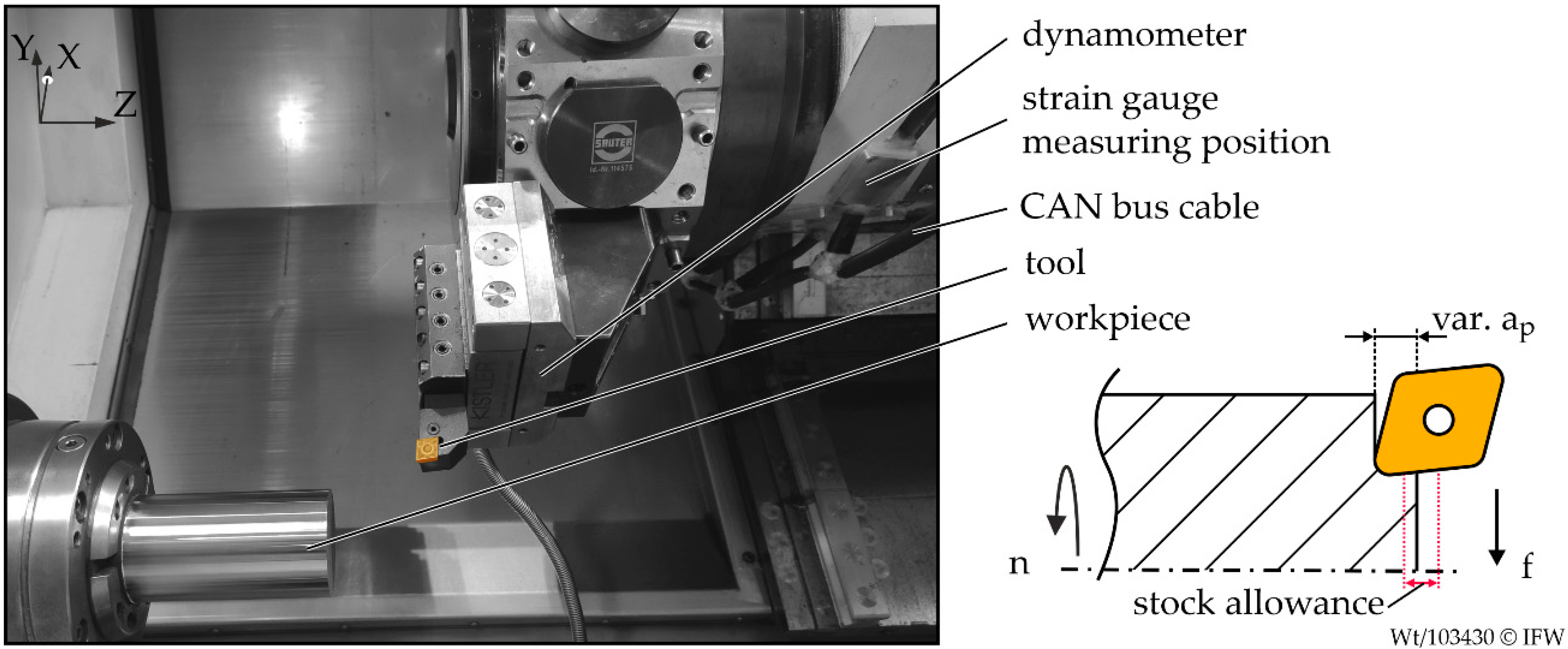
Experimental tests were performed on the turning center Gildemeister CTX420 linear (Bielefeld, Germany). The lathe is equipped with a feeling turret to measure the process forces. The sampling rate of the feeling turret was 1000 Hz with a selected low-pass filter of 25 Hz. The force resolution of the feeling turret is 64 N in the direction of passive force Fp, 43 N in the direction of cutting force Fc and 44 N in the direction of feed force Fz [16]. In addition, the process force was measured by a dynamometer (Kistler 9129A, Winterthur, Switzerland) with a sampling rate of 1000 Hz and a preset low-pass frequency of 30 Hz. The axis positions were provided by the numerical control via the field bus interface with a frequency of 83 Hz. An industrial personal computer (IPC) was connected to the field bus interface of the Siemens Powerline 840D machine control (München, Germany). Further, the IPC was connected to the CAN bus of the feeling turret. During the machining, indexable inserts with a CNMG120408 geometry from Garant were used (Reutlingen, Germany). The measurement setup is depicted in Figure 1.
Face turning operations were performed to investigate the confidence limits of a process monitoring approach. The depth of cut ap was varied between the processes, while the cutting speed vc and the feed rate f remained constant. For all processes, the material 20MnCr5 was machined. The workpieces exhibit a diameter of 60 mm and a length of 120 mm. Each process series included 100 facing operations. Process series with different depths of cut were carried out. Between the 100 facing operations, the stock allowance was randomly varied. After each process series, the indexable insert was replaced.
2.2. Monitoring Parameters
In addition to the measured cutting force Fc, it was analyzed, if the material-specific cutting force Fc,mat is suitable for monitoring process errors during machining workpieces with high stock allowance fluctuations. The forces were measured with the feeling machine and a dynamometer. The standardized force Fc,mat is approximately independent from the chip width and consequently from ap. Therefore, Fc,mat is more robust to variations in stock allowance, if the current material removal rate Qw (MRR) is known in a sufficient quality. The MRR was determined parallel to the process in a virtual layer by a dexel-based cutting simulation. The cutting simulation calculated the tool engagement conditions, e.g., cross-section of undeformed chip, based on the predefined geometry of the semi-finished part and the current position of the tool center point [13]. The workpiece was discretized by the dexel simulation with a resolution of 0.4 mm. The material-specific cutting force was calculated using the following equation.
Detailed investigations have already been carried out for the drop forging of steel components concerning the expected tolerance range [21]. According to this information, an expected tolerance range of −0.5 mm to +0.9 mm was defined for the investigations in this paper. The tolerance variations were according to the Weibull distribution. Based on process data of previous production steps or by process chain integrated measurement technology it is possible to predict the geometry after forming. However, this information is subject to a certain degree of uncertainty, depending on the method selected. This would lead to an inaccurate Fc,mat. To consider this error, the influence of geometric prediction errors on the sensitivity of the confidence limits was investigated. The geometric prediction errors can be assumed to be normally distributed in the first approach [25]. The 6σ range of the prediction error was varied in three steps. Based on the material-specific cutting forces Fc,mat6σ generated by this method, it was investigated which level of process uncertainty was allowed before the loss of sensitivity of the confidence limits exceeded a defined limit. The signal flow diagram is presented in Figure 2.
2.3. Monitoring Limits
The confidence limits for process monitoring were calculated based on the approach of the confidence estimator parallel to the machining process [26]. In this context, the monitoring signals presented in Section 2.2 were evaluated individually and an upper and lower confidence limit was calculated Lup,low. The approach provides that the confidence limits were updated after each process. Therefore, the expected mean value and the standard deviation σ for each current measurement value i was determined. For this purpose, the new measurements were compared with those already made and weighted about their actuality. Therefore, teaching processes are required at the beginning to generate reference values. Based on the safety value Csaftey, the distance between and the confidence limits were influenced. For the following investigations, a safety value Csaftey = 6 was used:
To take into account temporal variations, the confidence limit as a function h(i) was calculated. This function determines a confidence limit for the expected value x(i), which allows a time delay for a defined time K. For the investigations, K was set to 100 ms:
According to the combination of Equations (1) and (2), the shift of time and amplitude was taken into account during the calculation of the confidence limits. The values of h and σ were calculated by a moving average to allow dynamic weighting of the different measurements:
Based on the defined parameters Csaftey and K, a maximum of two false alarms could be ensured within a process series of 100 machining operations. The first ten processes that are necessary for the initial learning of the confidence limits were excluded.
3. Results and Discussion
3.1. Investigation of the Material-Specific Cutting Force for Process Monitoring
Process monitoring can be improved by using a specific monitoring parameter. This parameter has to be sensitive to process force changes without being affected by allowance fluctuation. The material-specific cutting force Fc,mat is a characteristic value that matches these properties. If the geometry of the workpiece is known, the actual MRR can be calculated using a cutting simulation. Based on the MRR the material-specific cutting force Fc,mat can be calculated, as shown in Figure 2. Due to the proportional relationship between ap and Fc, the standardization considers the stock allowance and the resulting confidence limits are closer to the signal and therefore more sensitive. The following section will discuss the results based on the dynamometer measurements.
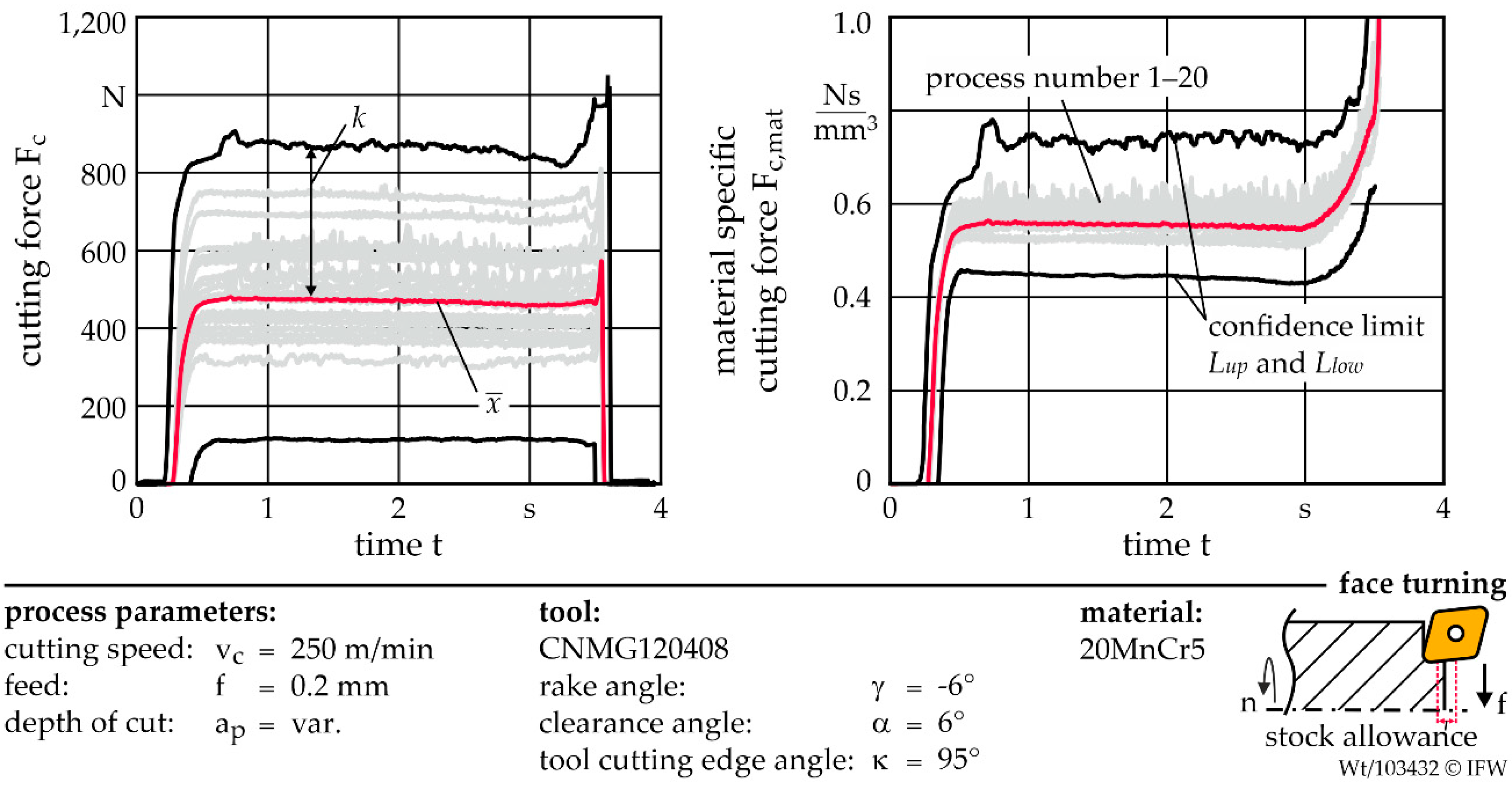
Figure 3 presents an example of the resulting confidence limits for processes with stock allowance fluctuations. For this purpose, twenty face turning operations were performed and ap was varied randomly based on the Weibull distribution defined in Section 2.2. The confidence limits were generated based on the cutting force Fc and the standardized material-specific cutting force Fc,mat.
To evaluate the sensitivity of the confidence limits of different signal sources the normed bandgap NB was calculated. The NB describes the distance k between the mean value and the lower or upper confidence limit Lup,low. Thus, NB defines the ratio by which the monitored signal has to change to detect a process error.
A small NB indicates a higher sensitivity of the confidence limits compared to a high NB. If the NB value increases to one, the distance between Lup,low and is as high as the amplitude of . As result, the lower confidence limit is zero. Consequently, process errors that cause a drop in force are not detected. This type of signal characteristic can be observed, if the tool breaks [27]. For this reason, a normed bandgap of one is defined as a limit value. If this is exceeded, robust monitoring of the tool breakage is not possible. If a process error results in the same percentage change for different signals, the NB can be used to directly compare the sensitivity of the signal sources. Since the cutting force Fc and the material-specific cutting force Fc,mat are determined with the same measuring system and therefore the percentage change is identical, the normed bandgap can be used to compare the two signals.
In the next step, the evolution of the NB based on the upper confidence limit was investigated for different signals and three process series. Therefore, the normed bandgap was averaged over the particular machining operation and the parameter was calculated. Each process series contains 100 facing operations with a nominal ap of 1 mm. To represent the stock allowance fluctuations, the deviation from the nominal value ap was randomly determined for each process from the previously defined Weibull distribution. The resulting stock allowance for the individual process numbers and process series A to C are shown in Figure 4a.
If the measured cutting force Fc is used to generate the confidence limits, the NB value increases significantly during the teach-in period of the first ten processes. Depending on the characteristics and distribution of the stock allowance fluctuation during the 100 performed processes, minor differences in the trend can be observed, depicted in Figure 4b. The variation of the normed bandgap for each process series is at = 1 and exceeds this limit several times. If the simulated MRR is used to standardize the cutting force, the can be significantly reduced. The variation among the three process series is also lower and the average is 0.27. The sensitivity to process errors that cause a change in the cutting force can thus be increased by a factor of four. Since the measurement series do not differ significantly, measurement series A is used in the following investigations.
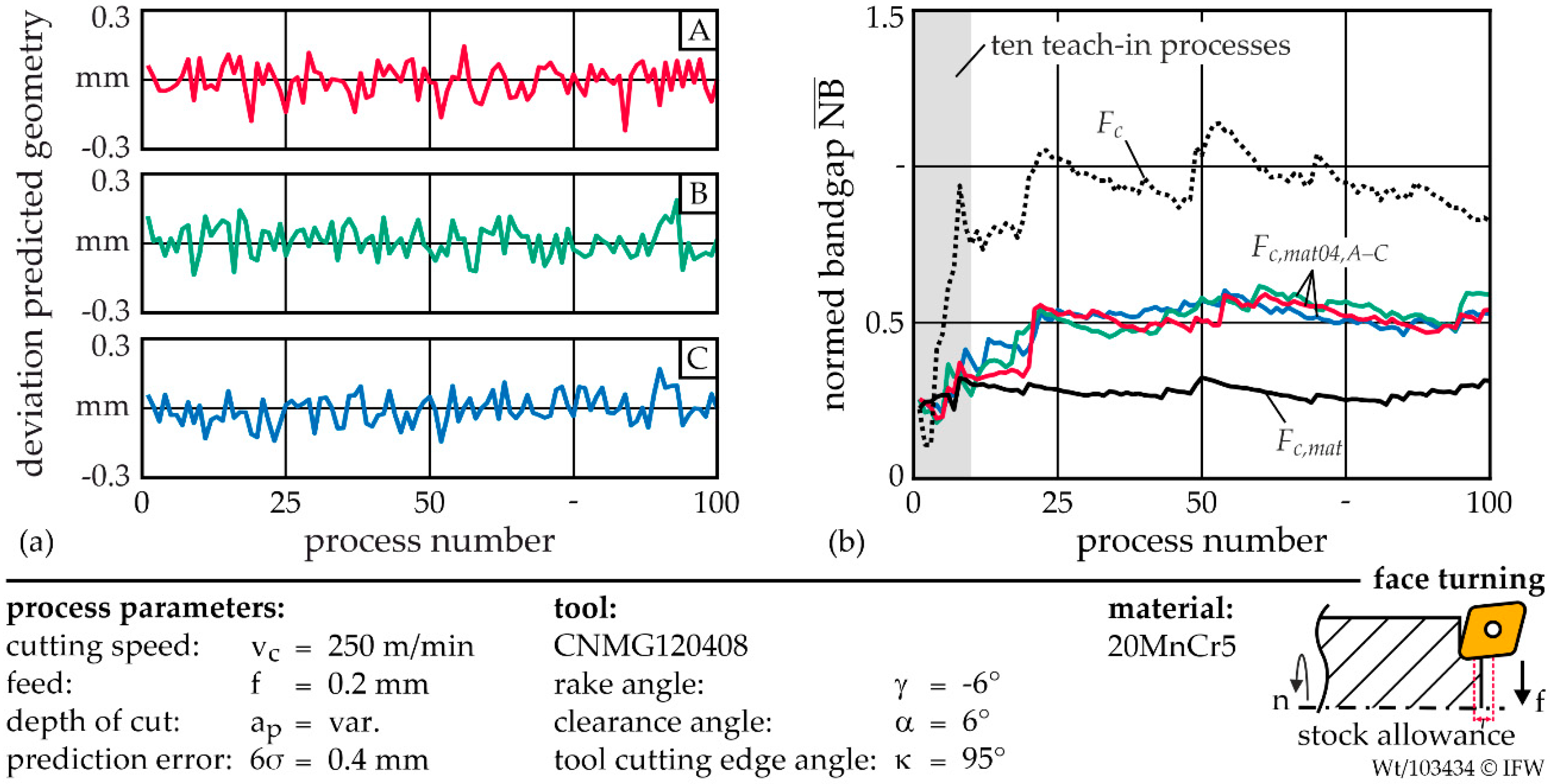
Since the process data-based prediction of the workpiece geometry is subject to errors, the impact of the resulting deviation from the actual MRR on the generated confidence limits is investigated. For this purpose, the actual depth of cut ap was assigned a random deviation within the cutting simulation. It was defined that the error is normally distributed and is located in a range of 6σ = 0.4 mm. As a result, a material-specific cutting force Fc,mat04 has been generated which represents an additional uncertainty. This was repeated three times for the investigation. The prediction errors for the 100 performed processes and the resulting are presented in Figure 5a.
The comparison of the shows that even, if the geometry prediction deviates from the actual shape, a significant increase in sensitivity is still achieved. If the error is normally distributed, no significant differences are determined for the evolution of . After 25 processes, the mean normed bandgap is about = 0.5 for all three process series. Consequently, the application of the material-specific cutting force is still twice as sensitive as the application of the cutting force, depicted in Figure 5b.
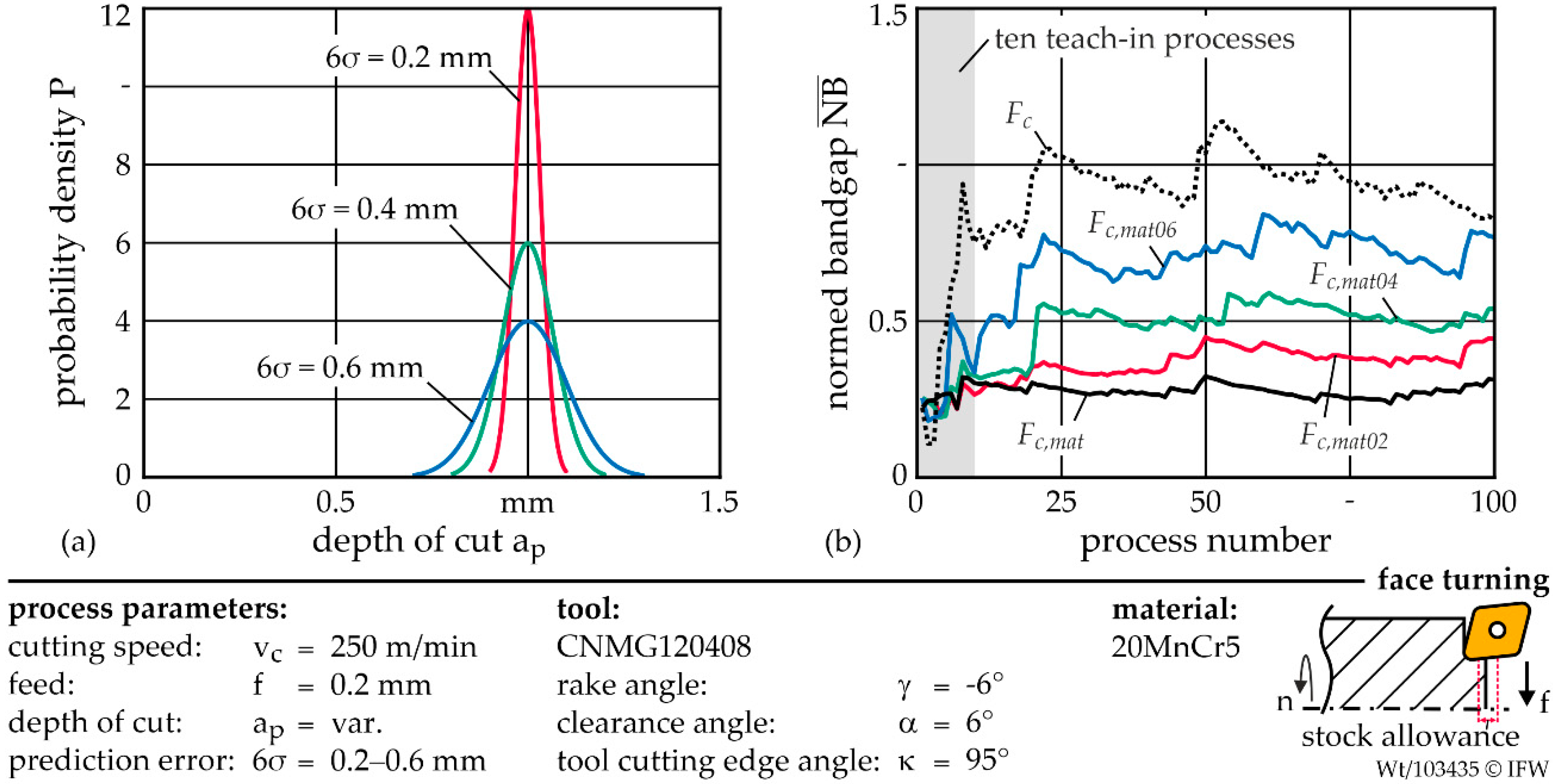
Next, the influence of the variation of the range of uncertainty 6σ on the generation of the confidence limits is investigated. The prediction error of the component geometry of 6σ is varied in three steps from 0.2 mm to 0.6 mm. Again, the process series A from Figure 4a was used. To account for the error in the predicted depth of cut, the normally distributed deviation A from Figure 5a was scaled according to the new range.
In Figure 6a the resulting normal distributions and their characteristics are visualized for a nominal ap of 1 mm. Figure 6b shows the resulting normed bandgaps for the cutting force Fc, the material-specific cutting force Fc,mat and the three signals that are subject to uncertainties Fc,mat6σ. Reducing the error range by half to 6σ = 0.2 mm also reduces the loss of sensitivity by about 50%. The increase of the prediction error range to 6σ = 0.6 mm leads to an increase of 25% compared to 6σ = 0.4 mm. Therefore, the behavior is approximately proportional. Even if the range of the normally distributed prediction error is 60% of the nominal depth of cut, the confidence limits of the material-specific cutting force show a higher sensitivity to process errors. The normed bandgap of the confidence limits is at maximum = 0.8 and after the first ten processes at no point higher than the of Fc.
3.2. Comparison of Dynamometer and Feeling Machine
In the following section, the application of the developed feeling machine in the context of process monitoring by material-specific cutting force is shown. Furthermore, the performance compared to a dynamometer is demonstrated. For this purpose, the cutting force reconstructed by strain gauges is evaluated identically to the previous section. The forces were measured simultaneously with the feeling machine and dynamometer. The results for the normed bandgaps based on signals of the feeling machine are depicted in Figure 7.
If the feeling machine is used to determine Fc,mat, an average of 0.43 is achieved. Thus, has increased by 0.16 compared to the dynamometer. The feeling machine is also less sensitive, if the three different normally distributed prediction errors are considered in the determination of Fc,mat6σ. For each of the three error ranges, is increased by an average of about 0.16 as well. As a result, the sensitivity of the feeling machine is partially lower for Fc,mat06 compared to Fc. However, if the prediction error is 6σ = 0.4 mm, the material-specific cutting force is more sensitive for the entire process series. Comparing the non-standardized cutting force signal Fc of the feeling machine with the dynamometer, the sensitivity is even slightly improved. This is explained by the fact that chip formation influences the force signal and affects the standard deviation of the measured signal. Due to the larger distance of the structure-integrated sensor technology of the feeling machine to the process, these effects will be dampened to a higher degree.
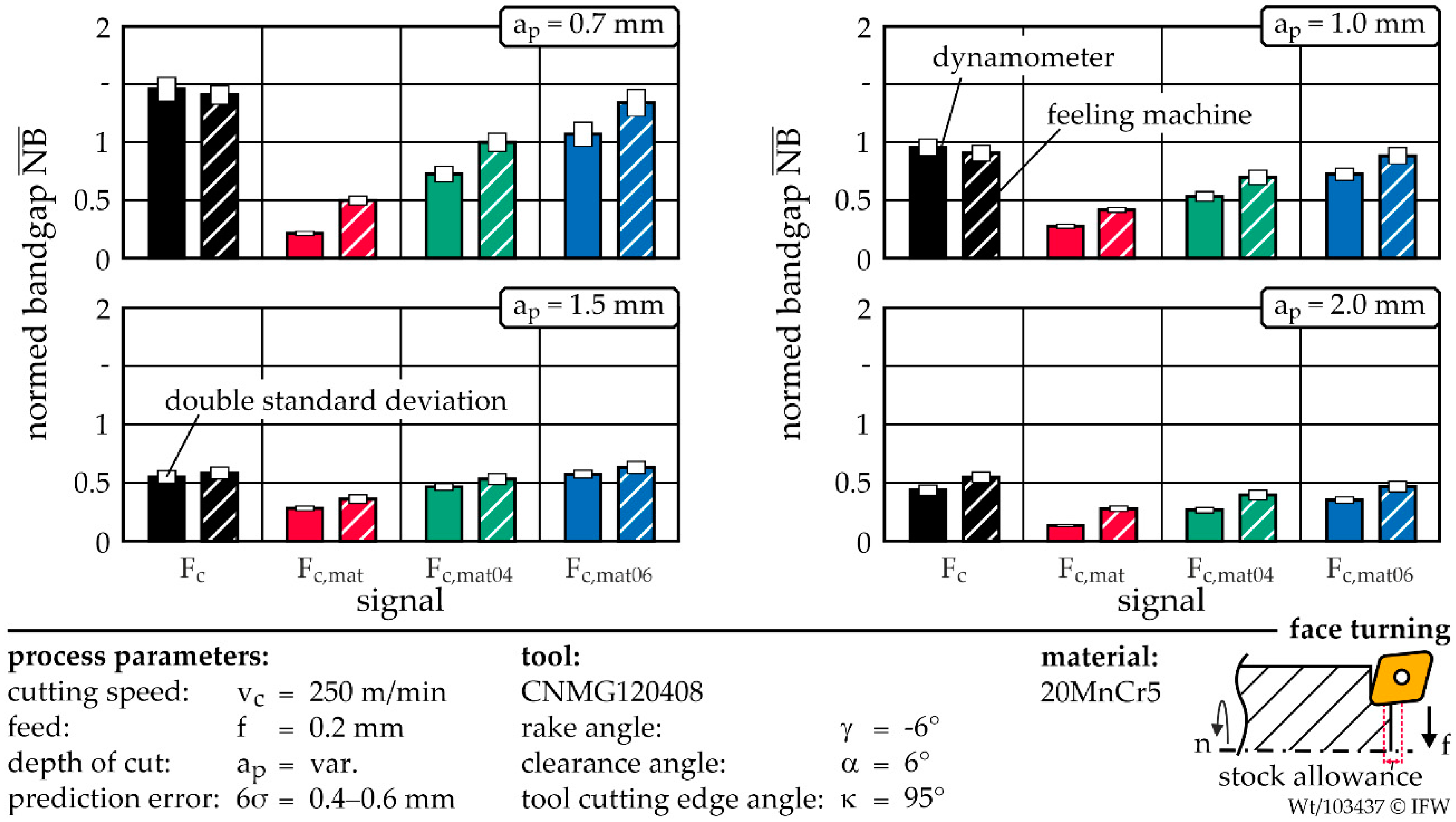
Finally, the sensitivity for both systems is determined for different depths of cut. For this purpose, the investigations are repeated for the depths of cut ap of 0.7 mm, 1.5 mm, and 2 mm. The sensitivities are shown for Fc, Fc,mat and the two prediction errors of 6σ = 0.4 mm and 6σ = 0.6 mm. The bar graphs depicted in Figure 8 represent the mean value over process numbers 51–100. For a depth of cut of 0.7 mm, the cutting force Fc from both signal sources has a low sensitivity with an above 1.4. The sensitivity to process errors is also insufficient for a prediction error of 6σ = 0.6 mm. If the prediction error range is reduced to 0.4 mm, the for the dynamometer and feeling machine is below one. In this case, the dynamometer has a significantly higher sensitivity. Compared to the feeling machine, the is lower by about 25% for Fc,mat04 and reduced by 50% for Fc,mat.
The evaluation of the process series with an initial ap of 1.5 mm shows that all considered signals are below = 1. However, the material-specific cutting force only performs better, if 6σ is less or equal to 0.4mm. While the sensitivity of Fc has improved significantly compared to ap = 1 mm, the sensitivity of Fc,mat increases poorly. This is because as ap increases, the relative percentage of the incorrect ap prediction decreases and therefore contributes less to an absolute variation of the cutting force. In addition, the chip formation mechanism can vary for individual process parameters, which represents an additional disturbance variable in the generation and evaluation of the confidence limits. For an initial depth of cut of ap = 2 mm, the sensitivity of the confidence limits based on Fc increases again slightly and the for the dynamometer is less than 0.5. However, all three investigated material-specific cutting forces have a higher sensitivity than the cutting force Fc. Compared to ap = 1.5 mm, the normed bandgap of Fc,mat has improved significantly and is now 0.13, if the dynamometer is used. For the feeling machine, the normed bandgap is 0.27.
The use of the material-specific cutting force has advantages for process monitoring in terms of sensitivity to the cutting force signal. However, the uncertainty in the determination of the workpiece geometry should not exceed 6σ = 0.4 mm to guarantee this advantage for different depths of cut, if the feeling turret is used.
4. Conclusions
In this paper, the application of a new characteristic value for confidence limit based process monitoring of workpieces with stock allowance fluctuations is investigated. For this purpose, the cutting force is measured and standardized based on the online simulated material removal rate. Furthermore, for the first time, the feeling machine and the dynamometer are compared with regard to their suitability for monitoring components with dimensional deviations. The signal sensitivity of both systems is compared based on the normed bandgap . For each process series, 100 facing processes are performed. If the information about the geometry of the semi-finished part is available, the MRR can be simulated and the material-specific cutting force Fc,mat can be calculated. The investigations show that the use of Fc,mat is significantly more sensitive to process errors than the non-standardized cutting force Fc. This is due to the fact that Fc,mat is not influenced by the actual depth of cut for a wide range of process parameters. For the investigated machining process, the sensitivity of the confidence limits for the process parameters vc = 250 m/min, f = 0.2 mm and ap = 1 mm is higher by a factor of 4. The sensitivity also varies less between the different process series, if Fc,mat is used. To take into account that inaccurate geometry information leads to an additional fluctuation in the calculation of Fc,mat, the ap was provided with a normally distributed error. The analysis demonstrates that even if this error increases to a range of 6σ = 0.4 mm, the use of Fc,mat is still more sensitive for both systems. This is valid for all examined ap. If the dynamometer is used, the Fc,mat has a higher sensitivity even with an uncertainty of 6σ = 0.6 mm. However, the sensitivity of the confidence limits generated by the feeling turret is also sufficient. For the investigated boundary conditions, the technology can be used for process monitoring of tool breakage, if an initial depth of cut of higher than 1 mm is selected. The new characteristic value Fc,mat can be used for any turning operation. The only requirement is the information about the process force and a cutting simulation to calculate the MRR.
Author Contributions
Conceptualization, M.W. and B.B.; Funding acquisition, B.D. and B.B.; Investigation, M.W.; Methodology, M.W. and B.B.; Supervision, B.D.; Validation, B.B.; Writing—original draft, M.W.; Writing—review and editing, B.D. and B.B. All authors have read and agreed to the published version of the manuscript.
Funding
The results presented in this paper were obtained within the Collaborative Research Centre 1153 ‘‘Process chain to produce hybrid high-performance components by Tailored Forming’’ in the subproject B5 (252662854). The authors would like to thank the German Research Foundation (DFG) for its financial and organizational support of this project.
Institutional Review Board Statement
Not applicable.
Informed Consent Statement
Not applicable.
Conflicts of Interest
The authors declare no conflict of interest.
References
- Siddhpura, A.; Paurobally, R. A review of flank wear prediction methods for tool condition monitoring in a turning process. Int. J. Adv. Manuf. Technol. 2013, 65, 371–393. [Google Scholar] [CrossRef]
- Teti, R.; Jemielniak, K.; O’Donnell, G.; Dornfeld, D. Advanced monitoring of machining operations. Ann. CIRP 2010, 59, 717–739. [Google Scholar] [CrossRef] [Green Version]
- Rehorn, A.G.; Jiang, J.; Orban, P.E. State-of-the-art methods and results in tool condition monitoring: A review. Int. J. Adv. Manuf. Technol. 2005, 26, 693–710. [Google Scholar] [CrossRef]
- Dan, L.; Mathew, J. Tool wear and failure monitoring techniques for turning-A review. Int. J. Mach. Tools Manuf. 1990, 30, 579–598. [Google Scholar] [CrossRef]
- Dimla, D.E. Sensor signals for tool-wear monitoring in metal cutting operations-a review of methods. Int. J. Mach. Tools Manuf. 2000, 40, 1073–1098. [Google Scholar] [CrossRef]
- Balsamo, V.; Caggiano, A.; Jemielniak, K.; Kossakowska, J.; Nejman, M.; Teti, R. Multi Sensor Signal Processing for Catastrophic Tool Failure Detection in Turning. Procedia CIRP 2016, 41, 939–944. [Google Scholar] [CrossRef]
- Novak, A.; Wiklund, H. On-Line Prediction of the Tool Life. Ann. CIRP 1996, 45, 93–96. [Google Scholar] [CrossRef]
- Altintas, Y. Prediction of cutting forces and tool breakage in milling from feed drive current measurement. J. Eng. Industry 1992, 114, 386–392. [Google Scholar] [CrossRef]
- Shinno, H.; Hashizume, H.; Yoshioka, H. Sensor-less Monitoring of Cutting Force during Ultraprecision Machining. Ann. CIRP 2003, 52, 303–306. [Google Scholar] [CrossRef]
- Yamada, Y.; Kakinuma, Y. Sensorless cutting force estimation for full-closed controlled ball-screw-driven stage. Int. J. Adv. Manuf. Technol. 2016, 87, 3337–3348. [Google Scholar] [CrossRef]
- Lauro, C.H.; Brandão, L.C.; Baldo, D.; Reis, R.A.; Davim, J.P. Monitoring and processing signal applied in machining processes-A review. Measurement 2014, 58, 73–86. [Google Scholar] [CrossRef]
- Kumme, R.; Mack, O.; Bill, B.; Haab, H.R.; Gossweiler, C. Investigation of Piezoelectric Force Measuring Devices in Force Calibration and Force Standard Machines. In Proceedings of the 17th International Conference on Force, Mass, Torque and Pressure Measurement IMEKO TC3, Istanbul, Turkey, 17–21 September 2001; pp. 92–103. [Google Scholar]
- Altintas, Y.; Kersting, P.; Biermann, D.; Budak, E.; Denkena, B.; Lazoglu, I. Virtual process systems for part machining operations. Ann. CIRP 2014, 63, 585–605. [Google Scholar] [CrossRef]
- Denkena, B.; Boujnah, H. Feeling machines for online detection and compensation of tool deflection in milling. Ann. CIRP 2018, 67, 423–426. [Google Scholar] [CrossRef]
- Denkena, B.; Mörke, T. Cyber-Physical and Gentelligent Systems in Manufacturing and Life Cycle. Genetics and Intelligence-Keys to Industry 4.0, 1st ed.; Academic Press: Cambridge, MA, USA, 2017; pp. 308–315. [Google Scholar]
- Bergmann, B.; Witt, M. Feeling machine for material-specific machining. Ann. CIRP 2020, 69, 353–356. [Google Scholar] [CrossRef]
- Denkena, B.; Bergmann, B.; Witt, M. Feeling Machine for Process Monitoring of Turning Hybrid Solid Components. Metals 2020, 10, 930. [Google Scholar] [CrossRef]
- Zhou, Y.; Xue, W. Review of tool condition monitoring methods in milling processes. Int. J. Adv. Manuf. Technol. 2018, 96, 2509–2523. [Google Scholar] [CrossRef]
- Bhat, N.N.; Dutta, S.; Vashisth, T.; Pal, S.; Pal, S.K.; Sen, R. Tool condition monitoring by SVM classification of machined surface images in turning. Int. J. Adv. Manuf. Technol. 2016, 83, 1487–1502. [Google Scholar] [CrossRef]
- Abellan-Nebot, J.V.; Subirón, F.R. A review of machining monitoring systems based on artificial intelligence process models. Int. J. Adv. Manuf. Technol. 2010, 47, 237–257. [Google Scholar] [CrossRef]
- EN 10243-1. Steel Die Forgings-Tolerances on Dimensions-Part 1: Drop and Vertical Press Forgings; DIN: Berlin, Germany, 2000. [Google Scholar]
- Pater, Z. Cross-wedge rolling. Compr. Mater. Process. 2014, 3, 211–279. [Google Scholar] [CrossRef]
- Kirchen, I.; Vogel-Heuser, B.; Hildenbrand, P.; Schulte, R.; Vogel, M.; Lechner, M.; Merklein, M. Data-driven model development for quality prediction in forming technology. In Proceedings of the IEEE 15th International Conference on Industrial Informatics (INDIN), Emden, Germany, 24–26 July 2017; pp. 775–780. [Google Scholar] [CrossRef]
- Denkena, B.; Behrens, B.-A.; Bergmann, B.; Stonis, M.; Kruse, J.; Witt, M. Potential of process information transfer along the process chain of hybrid components for process monitoring the cutting process. Prod. Eng. 2021. [Google Scholar] [CrossRef]
- Gertsbakh, I. Measurement Theory for Engineers, 1st ed.; Springer-Verlag: Berlin, Germany, 2003. [Google Scholar] [CrossRef]
- Brinkhaus, J.W. Statistische Verfahren zur selbstlernenden Überwachung spanender Bearbeitungen in Werkzeugmaschinen: (Statistical Methods for Self-Teaching Monitoring of Machining Operations in Machine Tools). Ph.D. Thesis, Leibniz University, Hannover, Germany, 5 May 2009. [Google Scholar]
- Tlusty, J.; Andrews, G.C. A Critical Review of Sensors for Unmanned Machining. Ann. CIRP 1983, 32, 563–572. [Google Scholar] [CrossRef]
Figure 1.
Presentation of the measurement setup.

Figure 2.
Visualization of the signal flow diagram for the determination of the material-specific cutting force.
Figure 2.
Visualization of the signal flow diagram for the determination of the material-specific cutting force.

Figure 3.
Confidence limits for Fc, and Fc,mat during face turning process with different depths of cut.
Figure 3.
Confidence limits for Fc, and Fc,mat during face turning process with different depths of cut.

Figure 4.
(a) Distribution of three process series with different stock allowance variation and (b) evolution of normed bandgaps for one hundred facing operations per series.
Figure 4.
(a) Distribution of three process series with different stock allowance variation and (b) evolution of normed bandgaps for one hundred facing operations per series.

Figure 5.
(a) Distribution of three process series with different deviation of the predicted geometry and (b) evolution of normed bandgaps for one hundred facing operations per series for stock allowance variation A.
Figure 5.
(a) Distribution of three process series with different deviation of the predicted geometry and (b) evolution of normed bandgaps for one hundred facing operations per series for stock allowance variation A.

Figure 6.
(a) Display of the probability density for three different prediction error ranges and (b) evolution of normed bandgaps for one hundred facing operations per series for stock allowance variation A, deviation of the predicted geometry A and the different prediction error ranges.
Figure 6.
(a) Display of the probability density for three different prediction error ranges and (b) evolution of normed bandgaps for one hundred facing operations per series for stock allowance variation A, deviation of the predicted geometry A and the different prediction error ranges.

Figure 7.
Comparison of the evolution of the normed bandgaps for one hundred facing operations per series for stock allowance variation A, deviation of the predicted geometry A and the different prediction error ranges by using signals provided by the feeling machine.
Figure 7.
Comparison of the evolution of the normed bandgaps for one hundred facing operations per series for stock allowance variation A, deviation of the predicted geometry A and the different prediction error ranges by using signals provided by the feeling machine.

Figure 8.
Comparison of the normed bandgaps for different initial depths of cut for stock allowance variation A, deviation of the predicted geometry A and the different prediction error ranges by using a dynamometer or the feeling machine.
Figure 8.
Comparison of the normed bandgaps for different initial depths of cut for stock allowance variation A, deviation of the predicted geometry A and the different prediction error ranges by using a dynamometer or the feeling machine.

Publisher’s Note: MDPI stays neutral with regard to jurisdictional claims in published maps and institutional affiliations. |
© 2021 by the authors. Licensee MDPI, Basel, Switzerland. This article is an open access article distributed under the terms and conditions of the Creative Commons Attribution (CC BY) license (http://creativecommons.org/licenses/by/4.0/).
Share and Cite
MDPI and ACS Style
Denkena, B.; Bergmann, B.; Witt, M. Feeling Machine for Process Monitoring of Components with Stock Allowance. Machines 2021, 9, 53. https://0-doi-org.brum.beds.ac.uk/10.3390/machines9030053
AMA Style
Denkena B, Bergmann B, Witt M. Feeling Machine for Process Monitoring of Components with Stock Allowance. Machines. 2021; 9(3):53. https://0-doi-org.brum.beds.ac.uk/10.3390/machines9030053
Chicago/Turabian StyleDenkena, Berend, Benjamin Bergmann, and Matthias Witt. 2021. "Feeling Machine for Process Monitoring of Components with Stock Allowance" Machines 9, no. 3: 53. https://0-doi-org.brum.beds.ac.uk/10.3390/machines9030053
Note that from the first issue of 2016, this journal uses article numbers instead of page numbers. See further details here.