Article

Thermodynamic Performance Analysis of Solar Based Organic Rankine Cycle Coupled with Thermal Storage for a Semi-Arid Climate

School of Mechanical Engineering & IEDT, Kyungpook National University, Daegu 41566, Korea
*
Author to whom correspondence should be addressed.
Submission received: 18 March 2021 / Revised: 7 April 2021 / Accepted: 15 April 2021 / Published: 28 April 2021
(This article belongs to the Section Electromechanical Energy Conversion Systems)

Abstract

:
This study focuses on the thermodynamic performance analysis of the solar organic Rankine cycle (SORC) that uses solar radiation over a moderate temperature range. A compound parabolic collector (CPC) was adjusted to collect solar radiation because of its long-lasting nature and featured low concentration ratios, which are favorable for moderate temperature applications. A thermal storage tank was fixed to preserve the solar energy and ensure the system’s continuous performance during unfavorable weather. However, water was used as the heat transfer fluid and R245fa was used as the working fluid in this system. The performance in both the hottest and coldest months was analyzed using the average hourly profile in MATLAB using weather data from Riyadh, Saudi Arabia. Variations in the tank temperature during the charging and discharging modes were found. The hourly based thermal efficiency and net power output for both configurations were also compared. The results show that at 17:00, when the cycle was about to shut down, the thermal efficiency was 12.79% and the network output was 16 kW in July, whereas in January, the efficiency was ~12.80% and the net power output was 15.54 kW.

1. Introduction

Fossil fuel depletion and its strong environmental impact have urged researchers to discover alternative resources to eradicate their deadly consequences. Development in the field of renewable energy resources is diminishing our high dependence on non-renewable energy resources by significant proportions. The use of renewable energy resources seeks to resolve the energy crisis and attain sustainable human development through its capability to deplete fossil fuel consumption and minimize environmental hazards. Greenhouse gases from fossil fuel combustion have a significant negative impact on the environment and are a serious unforeseeable cause of global climate change. Hence, the weather is becoming colder, wetter, and hotter. Moreover, as the sea level rises, it makes a vast portion of the Earth untenantable as proclaimed by the Intergovernmental Panel Climate Change (IPCC) [1]. Therefore, alternative energy sources are urgently needed to tackle this inexorable global problem. Researchers have focused their attention on a variety of feasible alternatives for energy generation, including the use of solar energy, human waste, geothermal heat from the earth, flue gas from biogas combustion, and waste heat from power plants. Solar energy has immense capability for generating and producing clean energy, which has attracted a lot of attention, especially in the current period because of its minimal pollution and its immense possibilities for applications.
Saudi Arabia established the National Renewable Energy Program with a vital ambition to localize the kingdom’s renewable energy market while fulfilling the highest international standards, as a program focused on activating their local resources for renewable energy production. The country plans to produce a total of 9.5 gigawatts of renewable energy by 2023, with an incremental target of 3.45 gigawatts in 2020 [2]. Under the United Nations Climate Change Conference (2012) in Qatar, Saudi Arabia declared its aim of supplying a third of its solar power demand by 2032 with 41 GW of solar capacity [3]. The ORC application, which uses renewable energy, has attracted significant attention for power generation. ORC is recommended due to its high efficiency in retrieving lower grade heat similar to solar energy, geothermal energy, waste heat, and marine thermal energy [4,5]. ORC manifests excellent flexibility, better safety, excellent reliability, and simplicity [6]. The solar organic Rankine cycle propounds an effective technique for using solar energy. A new arrangement of the solar system with low temperature and regenerative ORC was represented, which comprises compound parabolic collectors and ORC [7]. Solar-based power plants are an attractive option as they can incorporate dry cooling and enable green energy in arid regions [8].
Different types of modern solar collectors, including parabolic trough and flat-panel collectors, solar towers, and dish-shaped receivers are used to generate solar energy to meet energy demand [9,10]. ORC is ideal for low-end heat-to-power conversion, evacuated tube or CPC collectors are suitable for solar energy collection and supply significant heat sources for the efficient performance of ORC [11]. Considering the low-temperature solar power generation of a CPC collector of low concentration ratio and ORC, we determined that it acquires a two-stage collector and heat storage device to increase the heat collection efficiency. CPC and ORC technology have also been analyzed to prove the system’s feasibility [12]. Jing et al. [13] introduced the low-temperature SORC, making use of R123 with a CPC; the effect of the collector inclination fixing, a relation linking the heat exchanger, CPC collector, and ORC evaporation temperature on system performance was analyzed. The results specify three factors with a notable effect on annual power production and are key points for optimization. The non-tracking type concentrated solar collector has thermal efficiency over the temperature range of 180 °C to 200 °C, which has generated a lot of attention [14]. These non-tracking concentrated collectors are known as CPC collectors. CPCs with smaller concentration ratios (less than 3) are capable of acquiring most of the diffuse radiation incident on their apertures and focus them without tracking the sun [15]. The characteristic of CPC as a solar collector is discussed and its advantages upon a flat plate and evacuated collector are presented [16,17]. The various CPC collectors are available in the industrial market and depend upon the proposed variables, they can be adjusted to the solar power generation system.
To achieve the standard performance of SORC, the system requires thermal energy storage devices (TES). Thermal energy storage is a key element of the solar power system evolution. The intermittent complexion of sunlight is a major flaw in solar power which causes disparity among the consumer needs and obtained heat source. However, connecting energy storage can switch the excessive energy from a peak-insolation interval to nighttime or a period of adverse weather conditions, therefore making the power system more efficient, dependable, and limber. The main advantage of solar ORC over photovoltaic technology is that cost-effective thermal energy storage devices can be used instead of electrochemical batteries, which store additional heat energy in its thermal rather than electrical form, which is cheaper than the current commercial batteries and has a longer service life [18]. A vast scale of TES was examined for use alongside solar power systems. The existing TES idea for larger-scale concentrated solar power (CSP) systems promotes that steam Rankine power plants generally use an indirect two-tank system to provide storage space to operate for 6 to 12 h at maximum capacity. In this adjustment, the molten salt mixture is pumped from the cold storage tank through the heat exchanger to the hot storage tank, where it is heated by the heat transfer oil of the solar field. To supply superheated vapor at 100 bar, the salt temperatures in the hot and cold storage tanks must be in the range of 390 °C–300 °C [19]. The single-tank thermocline technique is suggested as an inexpensive alternative to two-tank systems and usually comprises inexpensive fillers such as quartzite and granite particles to supply a greater specific heat capacity and minimize the requisite storage volume and additional heat transfer fluid cost [20,21]. A domestic-scale solar combined heat and power system coupled with the thermal energy storage solution was compared. The research was solicitous with estimating a range of latent and sensible TES for operating SORC [22].
Previously, researchers propounded and examined different arrangements of the solar ORC cycle, whereas some focused on amalgamating systems with thermal storage. Alvi et al. [23] modeled, simulated, and compared the phase change material storage tanks. In this system, flat plate collector array covering a total area of 150 m2 is used as a heat source, and a phase change material tank with a surface area of 25.82 m2 is used as a heat storage device for configurations. Selecting a working fluid is essential for efficient power generation from ORC, as the thermodynamic properties of the working fluid affect the thermal efficiency of the system [24]. R245fa and water were selected as the working fluids for direct and indirect SORC systems. Wang et al. [25] studied how the off-design model of an ORC cycle operated by solar energy is presented with the CPC collector to collect the solar radiation, and how the thermal storage is deployed to achieve the continuous operation of the entire system. The system is analyzed under different time frame conditions and decreased ambient temperature, where the system manages to produce the maximum average exergy efficiency in December and maximum net power output in July or in September. Wang et al. [26] established the mathematical models to simulate solar-driven regenerative ORC under steady-state conditions. It was added that by utilizing heat storage into the system, constant and smooth performance can be attained over a long period. Li et al. [27] discuss the dynamic performance of SORC with TES. The impact of storage capacity, solar variation, and evaporation temperature were examined. It was stated that storage capacity should be preferred according to solar variation to retrain dynamic impact. Freeman et al. [28] introduced a small domestic-scale combined solar heat and power system combined with ORC to analyze the capability of the system in the UK. The authors identified two factors to boost the performance of the system: increasing the efficiency of the solar collector while keeping the operating temperature ideal and allowing the cycle to attain a smooth, steady power output for progressing load profile.
However, the above studies reveal that the reviewed literature is mainly concerned with design and time simulation. Detailed modeling and analysis of the SORC component for the complete day based on real-time geographical data had not been reported yet. Therefore, the present study developed a comprehensive thermodynamic analysis of the SORC system based on a CPC, thermal energy storage, and an ORC that uses selected organic working fluids, namely R245fa due to its thermodynamic performance and zero effect on the environment. The novelty of this work shows the evaluation of the thermodynamic performance and the comparison of cycle performance based on an hourly basis. The paper includes:
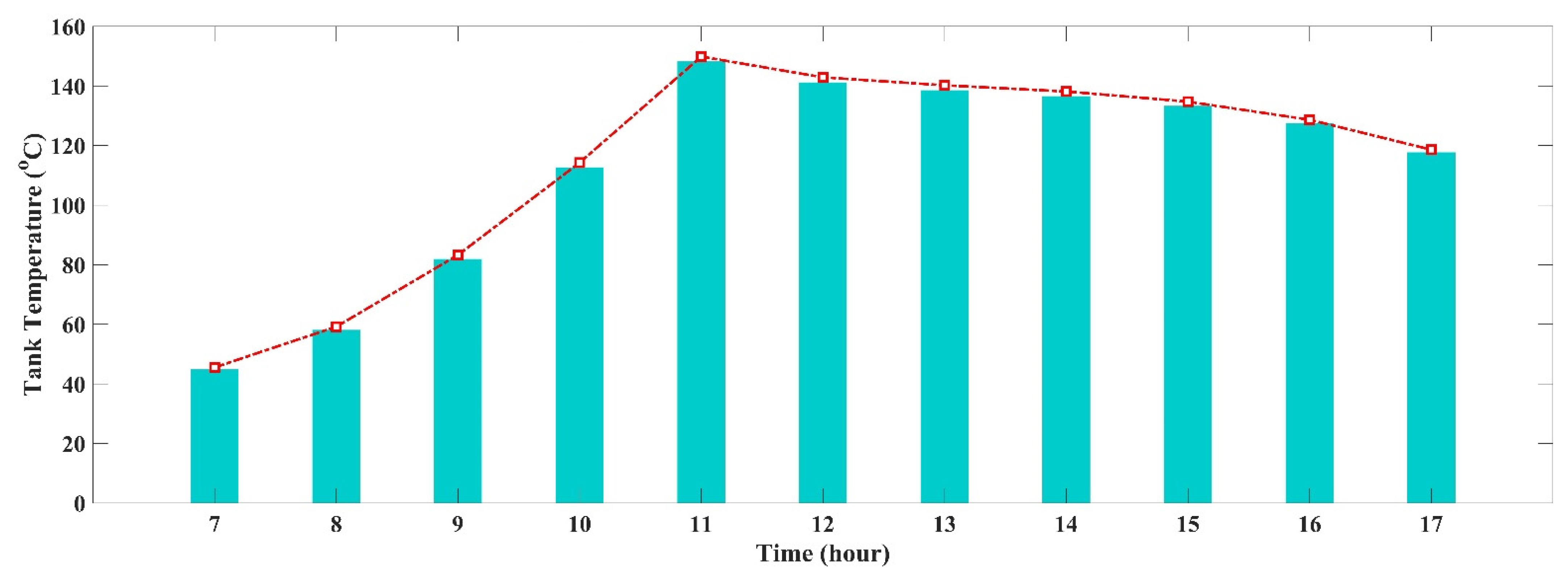
  • Temperature profile variation during the charging and discharging mode is indicated and compared under the hottest and coldest month of weather conditions on an hourly basis.
  • The thermodynamic performance of the system is based on the variation in the system efficiencies and net power output.

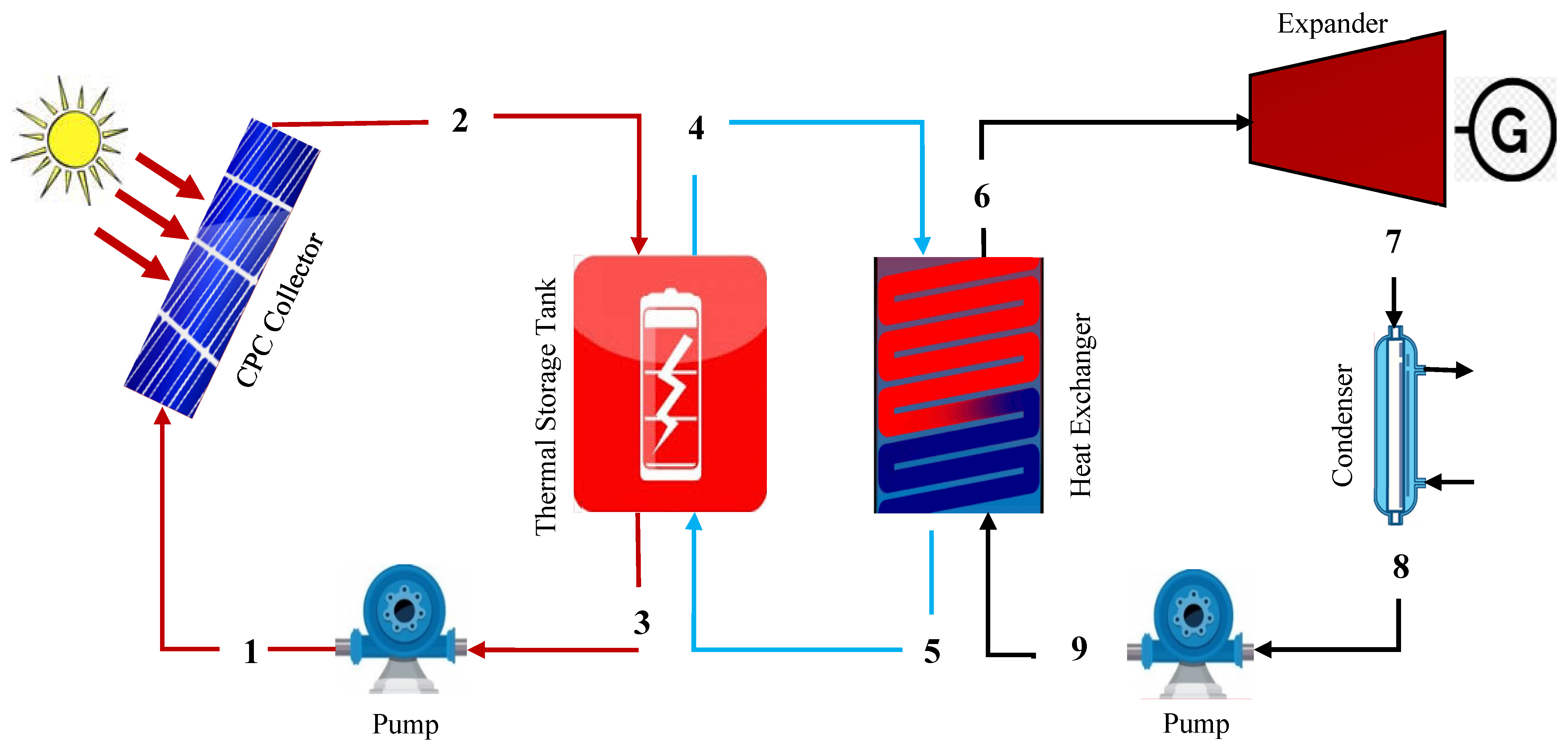
2. System Description

The schematic layout presents the amalgamation of the solar cycle and the organic Rankine cycle as shown in Figure 1. Here, the ORC cycle is driven through solar energy. The compound parabolic collector (CPC) at state 1 is adjusted to accumulate solar radiation due to its doable nature which allows CPCs to be employed in the absence of steady tracking, and also features low concentration ratios which are favorable for moderate temperature applications. A thermal energy storage (TES) tank with water (temperature range 45 °C–148 °C) at state 2 was affixed between the solar collector and the ORC to preserve the excess heat energy from the high-insolation periods until nighttime or periods of unfavorable meteorological conditions, through CPC, to establish the constant and steady performance of the overall system. A pump is used at state 3 to enhance the pressure of the heat source (water) to accelerate the heat energy in CPC.
However, the organic Rankine cycle includes the expander, condenser, pump, and heat exchanger. Where working fluid R245fa (ranging from 113 °C–143 °C) at state point 6 is passed through the expander after obtaining heat from the heat exchanger, is where it expands to produce the desired work output. State 5 is the outlet from the heat exchanger after supplying the heat to the ORC system. Then, state 7 undergoes a condensation process, where the working fluid is released from the expander, enters the condenser to dissipate heat through the cooling water, and transforms its phase from vapor to liquid, thereby obtaining a saturated liquid. Finally, the compression process in the pump occurs in state 8, which raises the pressure of the working fluid to the desired pressure. Finally, the working fluid is pumped back into the heat exchanger to continue a new cycle. In this cycle, the high-pressure working fluid reaches the heat exchanger at state point 9 and receives the preserved heat from the thermal energy storage, which enters the ORC system from state point 4.
In this case, Riyadh in Saudi Arabia is preferred as the reference location. Average hourly profiles based on direct normal irradiation (DNI) data are acquired by utilizing the Global Solar Atlas application [29] and the climatic daily average temperature data were obtained using the European Commission site [30]. Riyadh represents a hot desert climate with an intensely long hot summer while winter is mild and short. Thus, it is noted that July has the maximum DNI and the hottest month with greater ambient temperature, whereas January has the least DNI and is the coldest month of the year with minimal ambient temperature. The daily average ambient temperature together with the average hourly profiles of solar radiation received at collector surfaces for the entire day for both the month of summer and winter are shown in Figure 2, respectively.
The values of DNI data and climatic data were added to MATLAB to analyze each configuration with similar preconditions. The system was designed to start working as soon as the surface of solar collectors gains solar radiation. Charging and discharging are the two function modes of a storage system.

3. Thermodynamic Modeling

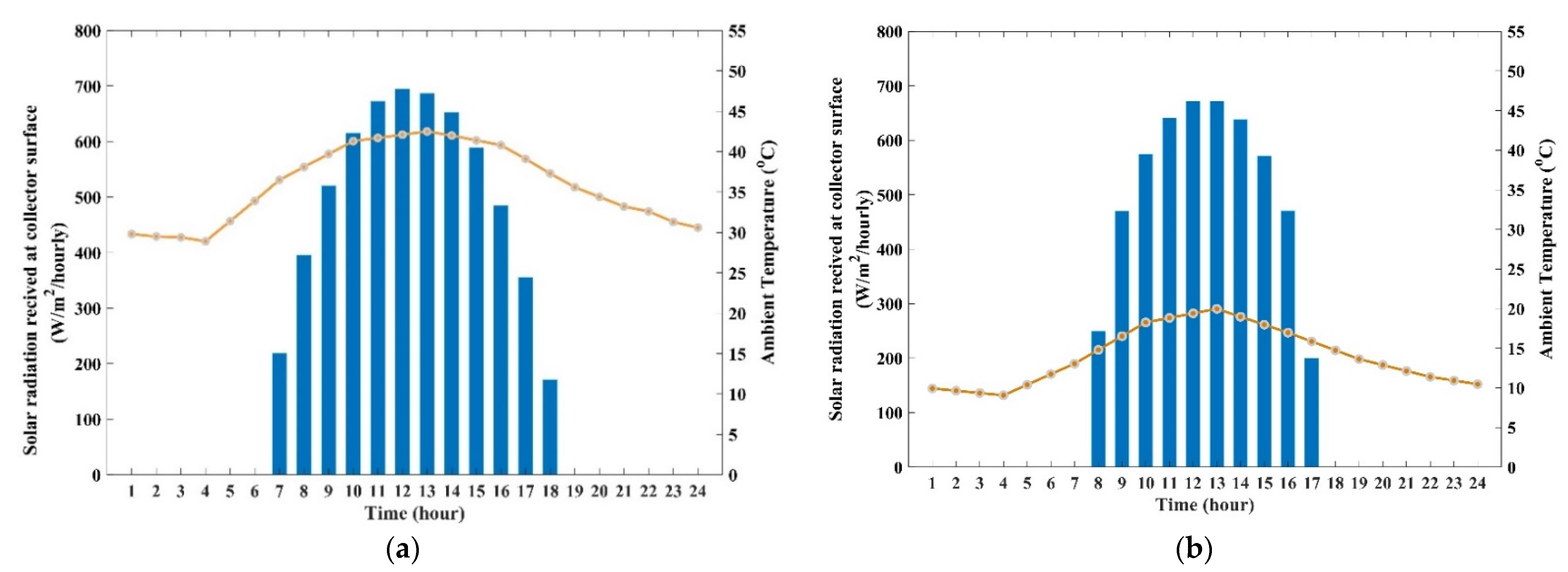
3.1. Solar Collectors

Solar collectors are used for absorbing solar energy, which involves both direct and scatters radiation. This includes various types such as a parabolic trough and flat-panel collectors which are used to generate solar thermal energy to meet energy demands. CPC collectors were used in this study, which is suitable for the energy collection from both beam and diffuse radiation and to supply a heat source for the efficient performance of ORC.
The solar collector thermal efficiency can be calculated as
η c o = a 0 a 1 ( T 1 T a m b ) D N I a 2 ( T 1 T a m b ) 2 D N I
where a 0 , a 1 and a 2 are the solar collector efficiency constant, a 0 is the efficiency of the collector, and a 1 and a 2 are the first and second heat loss coefficients. Here, T 1 means the inlet temperature to solar panel and T a m b means the ambient temperature.
The coefficient of solar collector efficiencies is shown in Table 1.
The amount of heat received from the collector can be calculated as
Q c o = η c o × D N I × N × A c o
The outlet temperature of the collector can be calculated as
T 2 = T 1 + Q c o m c p
here m c p is a mass of specific heat capacity.

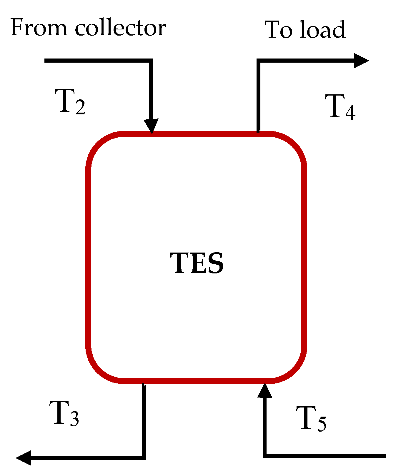
3.2. Thermal Energy Storage Tank

In the current system, it was assumed that a well-mixed sensible thermal energy storage system is used to collect the solar energy as shown in Figure 3, where the temperature of the water varies in a tank according to time. Moreover, the outside temperature of the tank T e n v was assumed to be constant and the losses in the water tank were also calculated.
Where T 2 is the outlet temperature of the collector, T 3 is an outlet from TES, T 4 is the load to drive ORC and T 5 is the rejected heat from the heat exchanger.
The heat balance in the tank can be obtained as
( ρ V c p ) d T s t o r d t = Q u Q l o a d U A ( T s t o r T e n v )
where Q u is the useful heat charging from the solar panel, Q l o a d is the discharging heat to drivers (ORC), T s t o r is the temperature of thermal energy storage and T e n v is the outside tank temperature, which can be calculated as
Q u = m c p ( T 2 T s t o r )
Q l o a d = m c p ( T s t o r T 5 )
Q l o s s = U A ( T s t o r T e n v )
The detailed mathematical modeling study of the TES tank and CPC collector were discussed in [31].
Water is used as a storage fluid at a pressure of 500 kPa in a sensible heat storage system. The cylindrical hot water storage tank had a diameter of 1 m, a height of 2 m, 0.006 m thickness, and was made of steel plate ( ρ = 7800 kg m−3, C p = 0.46 kJ kg−1 K−1). Additionally, 0.02 m-thick glass wool insulation material was used to completely insulate it. It is presumed that the starting temperature of the TES was 45 °C.

3.3. Organic Rankine Cycle

The basic configuration of the ORC system was modeled to simulate the present work. R245fa was used as a working fluid for ORC in the current study due to its low-temperature thermodynamic performance, and the fact that it has a critical temperature of 154 °C. The few assumptions made to simplify the analysis are as follows:
  • Pressure drops in the heat exchanger, condenser, and connecting pipes are neglected;
  • The system is assumed to be in steady-state condition;
  • The isentropic efficiency of the pump and expander are chosen, respectively.
The working fluid R245fa properties are listed in Table 2, including its ozone depletion potential (ODP) and global warming potential (GWP).
The parameters and assumptions used for the thermodynamic design of SORC are presented in Table 3.
The ratio of power generated in the expander can be calculated as
Q e x p = m O R C ( h 6 h 7 ) = m O R C ( h 6 h 7 s ) η e x p
where m O R C is the mass flow of the fluid in the organic Rankine cycle, h 6 inlet enthalpy to the expander, h 7 is the ideal outlet enthalpy from the expander while h 7 s is the isentropic enthalpy, and η e x p is the efficiency of the expander.
The heat rejected in condenser—ORC can be calculated as
Q c o n d = m O R C ( h 7 h 8 )
here h 8 (ideal enthalpy) outlet from the condenser.
The power consumed by the pump can be calculated as
Q P = m O R C ( h 9 h 8 ) = m O R C ( h 9 s h 8 ) / η P
Thus, the h 9 ideal outlet enthalpy from the pump, h 9 s an isentropic enthalpy and η P is the efficiency of the pump.
The heat transferred to the heat exchanger can be calculated as
Q h x = m O R C ( h 9 h 6 ) = m c p ( h 4 h 5 )
where m c p is specific heat capacity, h 4 an inlet to a heat exchanger and h 5 is the outlet from the heat exchanger.

4. Results and Discussion

The present work specifies Riyadh city in Saudi Arabia as a reference location having coordinates (24.63° N, 46.71° E) to examine performance on an hourly basis for a solar-based organic Rankine cycle in two different months. The average hourly profiles for the different months were taken, where January was selected as the coldest (winter) and July as the hottest (summer) month. A time frame of 24 h was chosen for the simulation process. A complete day simulation was carried out to determine the performance of both the hottest and the coldest months. The variation in temperature profiles during the charging and discharging mode was also compared.
Moreover, the variation in the results of system efficiencies and net power output for both winter and summer were also examined. MATLAB was used to perform the simulation to study the functioning of the system [32]. REFPROP [33], founded by the National Institute of Standards and Technology, was used to measure the thermodynamics properties of the working fluids.

4.1. Performance of July (Hottest) Month on an Hourly Basis

4.1.1. Variation in the Tank Temperature Profiles during Charging Mode

At the time of charging mode, the temperature profiles of the tank during the month of summer (July) are illustrated in Figure 4. The figure shows increasing trends in tank temperature with the increase in solar radiation. In the summer month of July, sunrise is at 07:00 a.m., at which time the solar system is turned ON to charge the TES with 10 kg/s mass flow. The mass flow of 10 kg/s was used to take advantage of the maximum amount of solar radiation at its peak time and store the most energy and heat in the thermal energy storage.
At the pressure of 500 kPa, the boiling point of the water reaches 150 °C, the parameter range selected for water as a working fluid has a maximum limit of 150 °C, and after this point, the working fluid starts to change its property and will change its property. From the figure, we can see that the system has attained a temperature of 148 °C at 11:00 a.m. after the 4 h of continuous charging. Thus, further increasing the temperature will lead to a change in the property and phase of the fluid. Due to which the system needs to start its discharging to prevent the phase change of the working fluid. However, TES then starts to discharge the energy stored from 11:00 a.m. to generate the work output from the SORC system. The results show that during the hottest month, the system manages to perform about 6 h a day. It should be noted that while discharging the stored energy from the tank, TES is also being charged for the longer run.

4.1.2. Variation in the Tank Temperature Profiles during Discharging Mode

During the time of discharging mode, the TES temperature reached 148 °C at 11:00 a.m. Above this, the working fluid may be affected. Thus, the system starts to discharge the TES to operate the ORC cycle from 11:00 a.m. until 17:00 p.m. when the temperature reaches 117 °C. After this point, the system is set to be stopped because the heat stored in the TES is not enough to supply the energy to the heat exchanger. However, Figure 4, shows the temperature drop in the tank as soon as the TES starts to discharge. However, at the same time, the system stores the energy in the tank as the solar radiation is still available so that the system can operate for a longer period. Thus, it can be seen that the system becomes discharged for 6 h to generate power output.

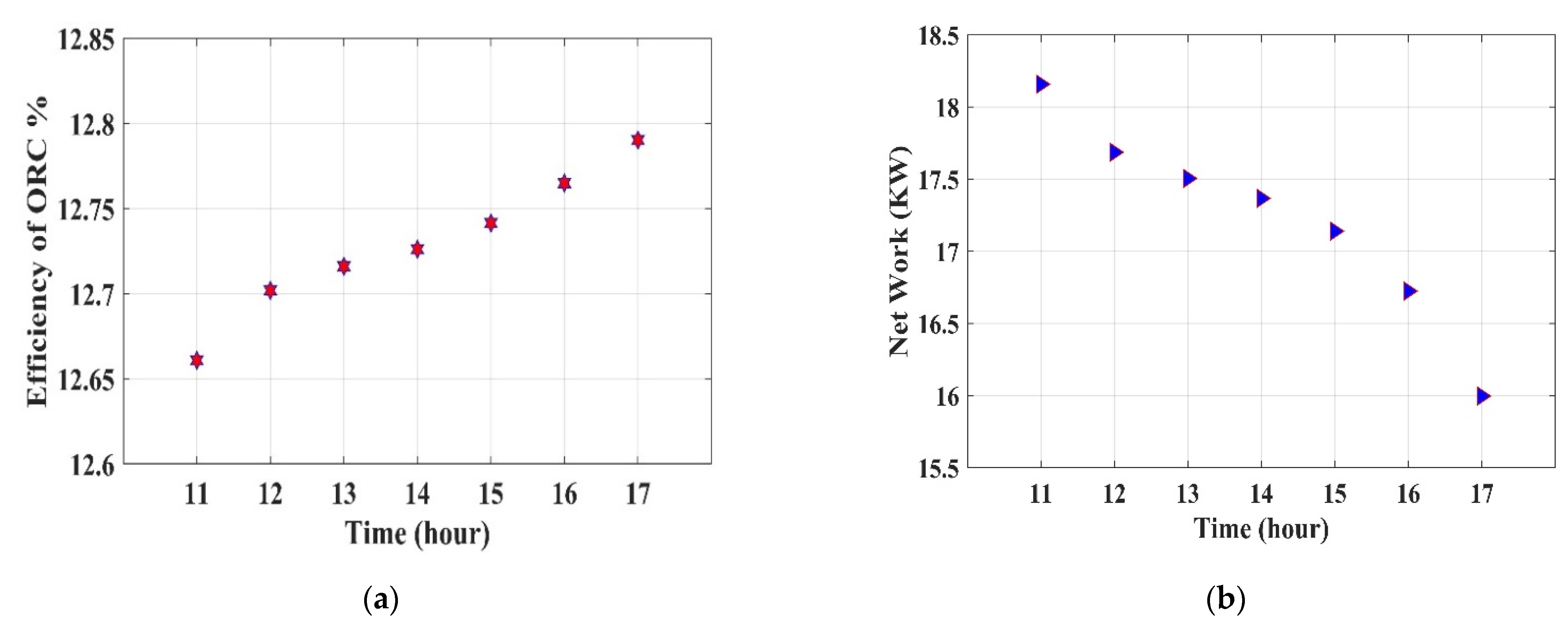
4.1.3. Variation in the System Efficiencies and Net Power Output

The system efficiencies and net power output of the system during the month of July can be seen in Figure 5. It can be observed that with the change in the time frame, there is a slight variation in the efficiencies and net power output of the system. The results show that with the increase in the efficiency of the system, the net power output decreases. Thus, at 11:00 a.m., the system has the least efficiency with 12.66%, whereas the net power output is greater with 18.1 kW; however, at 17:00 p.m., the system has an efficiency of 12.79% with the 16 kW of power output.

4.2. Performance of January (Coldest) Month on an Hourly Basis

4.2.1. Variation in the Tank Temperature Profiles during Charging Mode

Figure 6 shows the temperature profiles of the tank during the month of winter (January). In the month of winter, sunrise is at 08:00 a.m., at which time the system undergoes charging mode to operate the thermal storage tank. At the pressure of 500 kPa, in the month of January, the system attained a temperature of 120 °C at 11 a.m. after 3 h of charging. At 500 kPa, the boiling point of the water was 150 °C so further increasing the temperature of the TES will lead to an increase in the temperature of more than 150 °C, which will change the phase of the water. For a better performance of the system and to prevent the water from phase change, the thermal storage tank begins to discharge the stored energy at 11 a.m. to produce the net power output from the system. It is concluded that in the coldest month, the system achieves 6 h of work a day.

4.2.2. Variation in the Tank Temperature Profiles during Discharging Mode

In the winter month of January, due to the low solar radiation at the starting phase as compared to the summer month of July, the temperature in the tank attains 120 °C before discharging. Figure 6 shows that, at 11:00 a.m., the system starts the TES to discharge the stored energy to produce the work output. The graph trend in the figure shows the slight increment in the tank temperature, which is because it has a similar amount of solar radiation with 10 kg/s mass flow and the lower ambient temperature which results in a minimal loss in collectors.

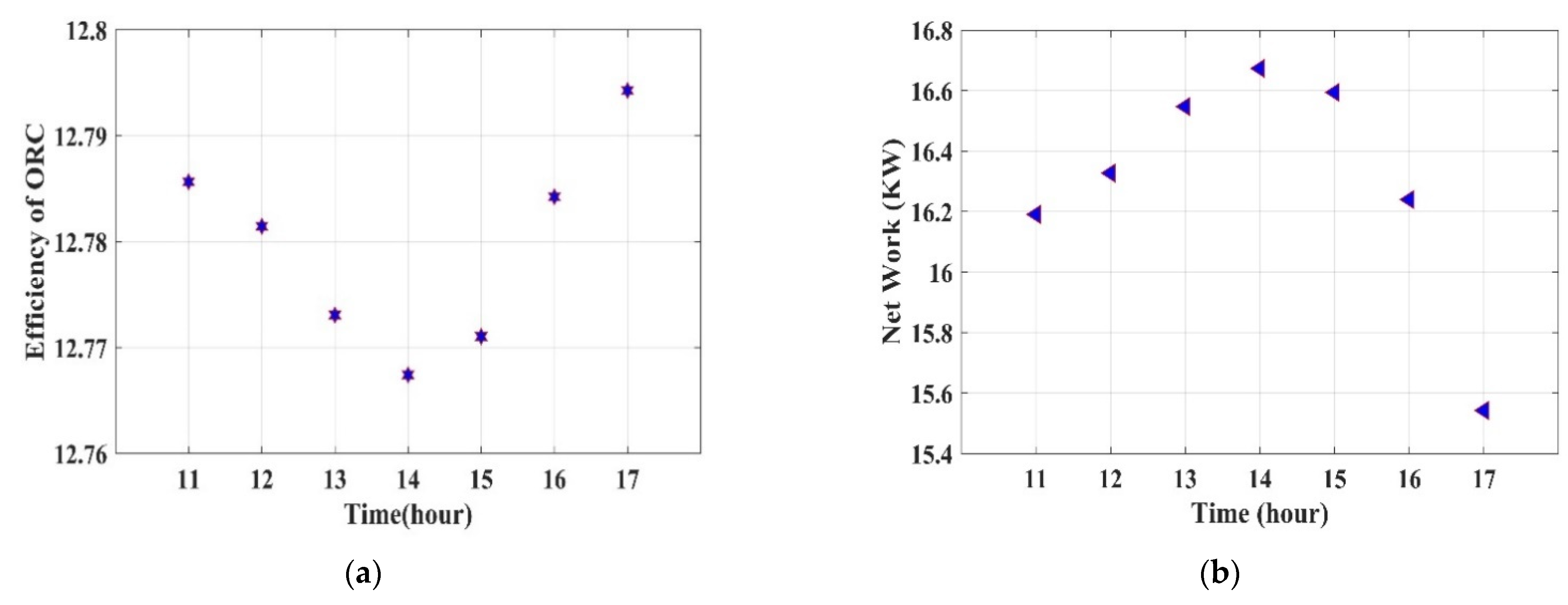
4.2.3. Variation in the System Efficiencies and Net Power Output

Figure 7 illustrates the system efficiencies and net power output of the system for January. The graph trend for system efficiency shows a slight decrement in the first half of the cycle and then starts to increase in the latter half, while the net power output of the system can be seen in the increasing trend in the first half of the interval and starts to decrease in the next half. The results indicate that the efficiency of the ORC system starts to decrease from 12.79% at 11:00 a.m. to around 12.70% at 14:00 p.m. and then again starts to increase to 12.79% at 17:00 p.m. While considering the net power output, it was seen to be increasing from 16.19 kW at 11:00 a.m. to 16.67 kW at 14:00 p.m. and further starts to decrease until 17:00 p.m. The presented results show that the efficiency of the system is nearly the same in both the hottest and coldest months of summer and winter, respectively, which is due to the direct normal radiation that is approximately the same in both cases, but due to the lower ambient temperature in winter, the losses are minimum in comparison with those in summer. However, this shows that the system is acceptable for use in semi-arid climates under different seasons.

5. Conclusions

In this paper, a moderate temperature solar organic Rankine cycle system has been designed, which consists of the CPC collectors, TES tank, and the power cycle. The thermal storage tank is established to preserve the excess heat energy from high-insolation periods to produce the stability and steady performance of the overall system. Solar energy is based on sunlight (solar radiation) which varies every hour depending upon the climate and location of the place. The study of this system establishes the hourly performance analysis which is possibly a better option to benefit the event of practically applying the solar energy cycle by computing the net output of the system for the entire day. The thermodynamic performance analysis of the tank temperature was compared for both the hottest and coldest months of the year. The system shows that the tank temperature profile changes with the time frame.
The results conclude that while the tank is in the charging mode, it attains a maximum temperature of 148 °C at 11:00 a.m. on a day in the summer month of July, which is 28 °C greater than that during the winter month of January. Whereas the result shows that in discharging mode, the system operates for 6 h a day with the tank temperature decreased to 118.6 °C, in summer as in winter, the system produces a work output for 6 h with the tank temperature decreased to 112.1 °C. The net power output of the system in July is greater at 11:00 a.m. with 18.1 kW, while in January, it is greater at 14:00 p.m. with the power output of 16.67 kW, as the average household electricity consumption in kWh per day is around 30 kWh, and thus this system is capable of providing more than 50% of energy support. The thermal efficiency is 12.79% in July while in January, efficiency is almost 12.80%—which is nearly the same because the direct normal radiation is approximately the same in both cases, however, due to the lower ambient temperature in winter, losses are minimal in comparison with summer. The model under given boundary conditions shows better overall thermal efficiencies in winter, thus the net power output of the system is higher in summer. The system presented the layout configuration which is simple and doable.

Author Contributions

Conceptualization, methodology, formal analysis, and original draft preparation by N.M.A.A. and B.K. M.-H.K. supervised the research and edited the manuscript. All authors have read and agreed to the published version of the manuscript.

Funding

This research received no external funding.

Institutional Review Board Statement

Not applicable.

Informed Consent Statement

Not applicable.

Data Availability Statement

Data are contained within the article.

Conflicts of Interest

The authors declare no conflict of interest.

Nomenclature

A area ( m 2 )
N number of collectors
Ttemperature (°C)
η efficiency (%)
Q heat rate (W)
m mass flow (Kg-s)
d t time
ρ density (Kg/ m 3 )
V volume ( m 3 )
U loss coefficient (W/m2K)
h specific enthalpy (J/kg)
sspecific entropy (J/kg·K)
Abbreviations
CPCcompound parabolic collector
TESthermal energy storage
SORCsolar organic Rankine cycle
ORCorganic Rankine cycle
DNIdirect normal irradiation (Wh/ m 2 )
Subscripts
a m b ambient temperature (°C)
c o collector
condcondenser
c p specific heat capacity (J/kg·K)
e n v outside tank temperature (°C)
expexpander
hxheat exchanger
Ppump
s t o r thermal energy storge

References

  1. Pachauri, R.K.; Allen, M.R.; Barros, V.R.; Broome, J.; Cramer, W.; Christ, R.; Church, J.A.; Clarke, L.; Dahe, Q.; van Ypserle, J.P.; et al. IPCC, 2014: Climate Change 2014: Synthesis Report. Contribution of Working Groups I, II and III to the Fifth Assessment Report of the Intergovernmental Panel on Climate Change; IPCC: Geneva, Switzerland, 2014. [Google Scholar]
  2. King Abdullah City for Atomic and Renewable Energy © 2020. Available online: https://www.energy.gov.sa/ar/FutureEnergy/RenewableEnergy/Pages/default.aspx (accessed on 6 November 2020).
  3. Boisgibault, L.; Al Kabbani, F. Energy Transition in Metropolises, Rural Areas and Deserts; John Wiley & Sons: Hoboken, NJ, USA, 2020. [Google Scholar]
  4. Tchanche, B.F.; Lambrinos, G.; Frangoudakis, A.; Papadakis, G. Low-grade heat conversion into power using organic Rankine cycles—A review of various applications. Renew. Sustain. Energy Rev. 2011, 15, 3963–3979. [Google Scholar] [CrossRef]
  5. Vetter, C.; Wiemer, H.J.; Kuhn, D. Comparison of sub- and supercritical Organic Rankine Cycles for power generation from low-temperature/low-enthalpy geothermal wells, considering specific net power output and efficiency. Appl. Therm. Eng. 2013, 51, 871–879. [Google Scholar] [CrossRef]
  6. Nafey, A.S.; Sharaf, M.A. Combined solar organic Rankine cycle with reverse osmosis desalination process: Energy, exergy, and cost evaluations. Renew. Energy 2010, 35, 2571–2580. [Google Scholar] [CrossRef]
  7. Pei, G.; Li, J.; Ji, J. Analysis of low temperature solar thermal electric generation using regenerative Organic Rankine Cycle. Appl. Therm. Eng. 2010, 30, 998–1004. [Google Scholar] [CrossRef]
  8. Khatoon, S.; Kim, M.H. Potential improvement and comparative assessment of supercritical Brayton cycles for arid climate. Energy Convers. Manag. 2019, 200, 112082. [Google Scholar] [CrossRef]
  9. Liu, Q.; Bai, Z.; Wang, X.; Lei, J.; Jin, H. Investigation of thermodynamic performances for two solar-biomass hybrid combined cycle power generation systems. Energy Convers. Manag. 2016, 122, 252–262. [Google Scholar] [CrossRef]
  10. Zhang, H.L.; Baeyens, J.; Degrève, J.; Cacères, G. Concentrated solar power plants: Review and design methodology. Renew. Sustain. Energy Rev. 2013, 22, 466–481. [Google Scholar] [CrossRef]
  11. Mills, D. Advances in solar thermal electricity technology. Sol. Energy 2004, 76, 19–31. [Google Scholar] [CrossRef]
  12. Gang, P.; Jing, L.; Jie, J. Design and analysis of a novel low-temperature solar thermal electric system with two-stage collectors and heat storage units. Renew. Energy 2011, 36, 2324–2333. [Google Scholar] [CrossRef]
  13. Jing, L.; Gang, P.; Jie, J. Optimization of low temperature solar thermal electric generation with Organic Rankine Cycle in different areas. Appl. Energy 2010, 87, 3355–3365. [Google Scholar] [CrossRef]
  14. Saitoh, T.S.; Kato, J.; Yamada, N. Advanced 3-D CPC solar collector for thermal electric system. Heat Transf. Asian Res. 2006, 35, 323–335. [Google Scholar] [CrossRef]
  15. Pereira, M.C. Design and Performance of a Novel Non-Evacuated 1. 2X Cpc Type Concentrator. Int. Sol. Energy Soc. 1986, 2, 1199–1204. [Google Scholar]
  16. Rabl, A.; O’Gallagher, J.; Winston, R. Design and test of non-evacuated solar collectors with compound parabolic concentrators. Sol. Energy 1980, 25, 335–351. [Google Scholar] [CrossRef] [Green Version]
  17. Saitoh, T.S.; Hoshi, A. Proposed solar Rankine cycle system with phase change steam accumulator and CPC solar collector. Proc. Intersoc. Energy Convers. Eng. Conf. 2002, 20150, 725–730. [Google Scholar]
  18. Colonna, P.; Casati, E.; Trapp, C.; Mathijssen, T. Organic Rankine cycle power systems: A review. In Proceedings of the International Conference on Power Engineering (ICOPE); The Japan Society of Mechanical Engineers: Tokyo, Japan, 2015. [Google Scholar]
  19. Kelly, B.; Kearney, D. Thermal Storage Commercial Plant Design Study for a 2-Tank Indirect Molten Salt System: Final Report, 13 May 2002–31 December 2004; National Renewable Energy Lab (NREL): Golden, CO, USA, 2002.
  20. Decker, T.; Burkhardt, J. Life Cycle Assessment of Thermal Energy Storage: Two-Tank Indirect and Thermocline; Energy Sustainability: San Francisco, CA, USA, 2017; pp. 1–2. [Google Scholar]
  21. Hoffmann, J.F.; Fasquelle, T.; Goetz, V.; Py, X. A thermocline thermal energy storage system with filler materials for concentrated solar power plants: Experimental data and numerical model sensitivity to different experimental tank scales. Appl. Therm. Eng. 2016, 100, 753–761. [Google Scholar] [CrossRef]
  22. Freeman, J.; Guarracino, I.; Kalogirou, S.A.; Markides, C.N. A small-scale solar organic Rankine cycle combined heat and power system with integrated thermal energy storage. Appl. Therm. Eng. 2017, 127, 1543–1554. [Google Scholar] [CrossRef]
  23. Alvi, J.Z.; Feng, Y.; Wang, Q.; Imran, M.; Alvi, J. Modelling, simulation and comparison of phase change material storage based direct and indirect solar organic Rankine cycle systems. Appl. Therm. Eng. 2020, 170, 114780. [Google Scholar] [CrossRef]
  24. Khatoon, S.; Almefreji, N.M.A.; Kim, M.-H. Thermodynamic Study of a Combined Power and Refrigeration System for Low-Grade Heat Energy Source. Energies 2021, 14, 410. [Google Scholar] [CrossRef]
  25. Wang, J.; Yan, Z.; Zhao, P.; Dai, Y. Off-design performance analysis of a solar-powered organic Rankine cycle. Energy Convers. Manag. 2014, 80, 150–157. [Google Scholar] [CrossRef]
  26. Wang, M.; Wang, J.; Zhao, Y.; Zhao, P.; Dai, Y. Thermodynamic analysis and optimization of a solar-driven regenerative organic Rankine cycle (ORC) based on flat-plate solar collectors. Appl. Therm. Eng. 2013, 50, 816–825. [Google Scholar] [CrossRef]
  27. Li, S.; Ma, H.; Li, W. Dynamic performance analysis of solar organic Rankine cycle with thermal energy storage. Appl. Therm. Eng. 2018, 129, 155–164. [Google Scholar] [CrossRef] [Green Version]
  28. Freeman, J.; Hellgardt, K.; Markides, C.N. An assessment of solar-powered organic Rankine cycle systems for combined heating and power in UK domestic applications. Appl. Energy 2015, 138, 605–620. [Google Scholar] [CrossRef] [Green Version]
  29. Global Solar Atlas. Available online: https://globalsolaratlas.info/map (accessed on 3 February 2021).
  30. European Commission. Available online: https://ec.europa.eu/jrc/en/PVGIS/docs/faq (accessed on 3 February 2021).
  31. Wang, J.; Dai, Y.; Gao, L.; Ma, S. A new combined cooling, heating and power system driven by solar energy. Renew. Energy 2009, 34, 2780–2788. [Google Scholar] [CrossRef]
  32. MATLAB Math Works—R2015a (Version 9.2). 2015. Available online: https://ch.mathworks.com/products/matlab/whatsnew.html (accessed on 3 February 2021).
  33. Lemmon, E.; Mc Linden, M.; Huber, M. NIST Reference Fluid Thermodynamic and Transport Properties Database: REFPROP Version 10. NIST Stand. Ref. Database 2018, 23, v7. [Google Scholar]
Figure 1. Schematic diagram of solar-based organic Rankine cycle.
Machines 09 00088 g001
Figure 2. Climatic data of Riyadh, Saudi Arabia, (average hourly profile): (a) hottest month; and (b) coldest month.
Machines 09 00088 g002
Figure 3. A well-mixed sensible thermal energy storage.
Machines 09 00088 g003
Figure 4. Variation in the tank temperature profiles during the charging and discharging mode in July.
Machines 09 00088 g004
Figure 5. Variation in the system efficiency (a); and net power output (b) during July.
Machines 09 00088 g005
Figure 6. Variation in the tank temperature profiles during the charging and discharging mode in January.
Machines 09 00088 g006
Figure 7. Variations in system efficiencies (a) and net power output (b) during the month of January.
Machines 09 00088 g007
Table 1. Design parameters of compound parabolic concentrators (CPC) [27].
Efficiency CoefficientFirst Heat Loss CoefficientSecond Heat Loss Coefficient
a 0 a 1   ( W / m 2   K ) a 2   ( W / m 2   K )
0.68310.21250.001672
Table 2. Properties of working fluid R245fa [24].
PropertyValue
Molar mass (Kg/kmol)134.05
Critical temperature (°C)154.01
Critical pressure (MPa)3.651
ODP0
GWP820
Table 3. Design parameter of solar organic Rankine cycle.
ParameterValueUnit
Number of CPC75-
Size of CPC2 m 2
Height of TES 2 m
The diameter of TES1 m
Thickness0.006 m
Expander efficiency 0.85%
Pump efficiency0.80%
Pinch point temperature in the evaporator 5°C
Pressure inlet to the expander1300kPa
Pressure outlet from the expander180kPa
Publisher’s Note: MDPI stays neutral with regard to jurisdictional claims in published maps and institutional affiliations.

