
Designing a Low-Cost Mechatronic Device for Semi-Automatic Saffron Harvesting


1
Department of Mechanical, Energy and Management Engineering (DIMEG), University of Calabria, 87036 Rende, Italy
2
Department of Mechanical and Aerospace Engineering (DIMEAS), Polytechnic of Turin, 10129 Turin, Italy
*
Author to whom correspondence should be addressed.
Machines 2021, 9(5), 94; https://0-doi-org.brum.beds.ac.uk/10.3390/machines9050094
Submission received: 2 April 2021
/
Revised: 4 May 2021
/
Accepted: 6 May 2021
/
Published: 9 May 2021
(This article belongs to the Special Issue Intelligent Machines and Control Systems)
Abstract
:This paper addresses the design of a novel mechatronic device for saffron harvesting. The main proposed challenge consists of proposing a new paradigm for semi-automatic harvesting of saffron flowers. The proposed novel solution is designed for being easily portable with user-friendly and cost-oriented features and with a fully electric battery-powered actuation. A preliminary concept design has been proposed as based on a specific novel cam mechanism in combination with an elastic spring for fulfilling the detachment of the flowers from their stems. Numerical calculations and simulations have been carried out to complete the full design of a proof-of-concept prototype. Preliminary experimental tests have been carried out to demonstrate the engineering feasibility and effectiveness of the proposed design solutions, whose concept has been submitted for patenting.
1. Introduction
Saffron is an important edible spice, which is used in several regional and international meals [1]. The production of saffron requires a complex process, which is mostly handled by manual workers, who need to bend their back for a significant amount of time with considerable discomfort and pain. In manual harvesting, a picker holds the stem of flowers between the thumb and index finger to separate it from the leaves. The fragile stem is broken through bending, then the picker can collect the flowers in a basket and go ahead to harvest the next saffron flower. The proposed device introduces a new harvesting approach that avoid pickers bending their backs, allowing a significant reduction of discomfort and pain while saving energy and improving the harvesting speed rate.
Multiple attempts have been made to automatize the saffron-harvesting process. Some examples are reported in [2,3,4,5,6,7], showing some semi-automatic and automatic systems aiming at solving both the absence of mechanization and the ergonomics of the operators. In both semi-automatic and automatic systems, the main design attention is addressed on the end-effector element, which plays a fundamental role in harvesting and detachment of the flower from the stem. In general, the end-effector is the main interface between the object to be manipulated and the user, as pointed out in several applications for the mechanical harvesting of horticultural products, such as reported for example in [8,9]. The literature reports multiple attempts of robotic hands for grasping objects [10,11,12,13,14], with some specific end-effectors designed for robotic harvesting such as reported in [15,16]. The main limitations of the existing solutions are that they are mostly designed for single-product applications [17,18], like tomatoes [19], strawberries [20] or cucumbers [21] while they result in being unsuitable for the mechanical harvesting of saffron, in particular, for the high fragility of saffron flowers where excessive applied forces will be strongly detrimental to the final quality of the spice.
One of the most interesting existing solutions for saffron harvesting is reported in [7]. This device is based on a pneumatic two-finger gripper that is capable of cutting the stem of saffron flowers while gently manipulating the flower. This solution was preliminarily experimentally tested showing promising harvesting rates. Nevertheless, the use of this device requires the availability of pressurized air for the pneumatic actuation system. Its use in the open field requires a compressor and an electric power supply, which makes the solution impractical from a portability viewpoint. Other fully automatic systems have been proposed in the literature as based on autonomous robot platforms in combination with complex electronic and mechanical components to identify, cut, collect, and store saffron flowers. One example of automatic harvesting systems is the Zaffy rover, featured in [3], which achieved a success rate of about 60%. Using an automatic system shows several limitations including the high cost of the initial investment, which is unsustainable for most of the small and medium-sized enterprises that deal with the production of saffron. Furthermore, the success rate of automatic systems has not yet reached sufficient levels, and it is still far lower than that of the human operator. Finally, many of the proposed solutions require production changes during the planting phase, requiring greater inter-row spaces to allowing sufficient space of large automatic machines. This reduces the production rates with a lower number of bulbs per square meter of land while the production of saffron is commonly limited to small land surfaces.
From the study of the state of the art emerges a strong need for a system that is simple and economic, with a productivity comparable to a human operator, and a low-cost, ergonomic, transportable, light, autonomous and semi-automatic. The proposed semi-automatic concept is an attempt to overcome the aforementioned limitations of both manual and automatic systems leading to significant productivity increases, reduction of required labor costs and efforts, while requiring a limited initial investment.
This paper addresses the design of a novel mechatronic device for a semi-automatic saffron harvesting. In particular, Section 2 focuses on materials and methods used for identifying the solution proposed. Section 3 focuses on conceptual design of solution, through the definition of the related technical and dynamic aspects. Section 4 shows the device dimensional synthesis with computer-aided design (CAD) modeling of the main components. Finally, Section 5 focuses on the rapid prototyping of the proposed end-effect. A preliminary experimental validation is reported in Section 6, to demonstrate the main functioning principles of the proposed device as well as its engineering feasibility.
2. Materials and Methods
Starting from the evaluation of the state of the art, a functional analysis was conducted. Table 1 reports a list of main tasks to be achieved with a proposal of solutions to fulfill them. The attached problem can be divided into two distinct parts. Namely, there should be a mechanical element (end-effector) that is able to make the cut on the stem without damaging the leaves, and an auxiliary device capable of allowing the movement and storage of the flowers. Once the flower has been separated from the plant, the second device will take the object from the work area and store it. Due to the great lightness of saffron flowers, a simple air flow can produce the required suction force to collect the flowers in a storage chamber.
An operator should be able to directly manage the operation of the proposed devices, as well as adjust some parameters such as the grasping force or the suction air flow. This requires a simple control unit with a user-friendly operation interface.
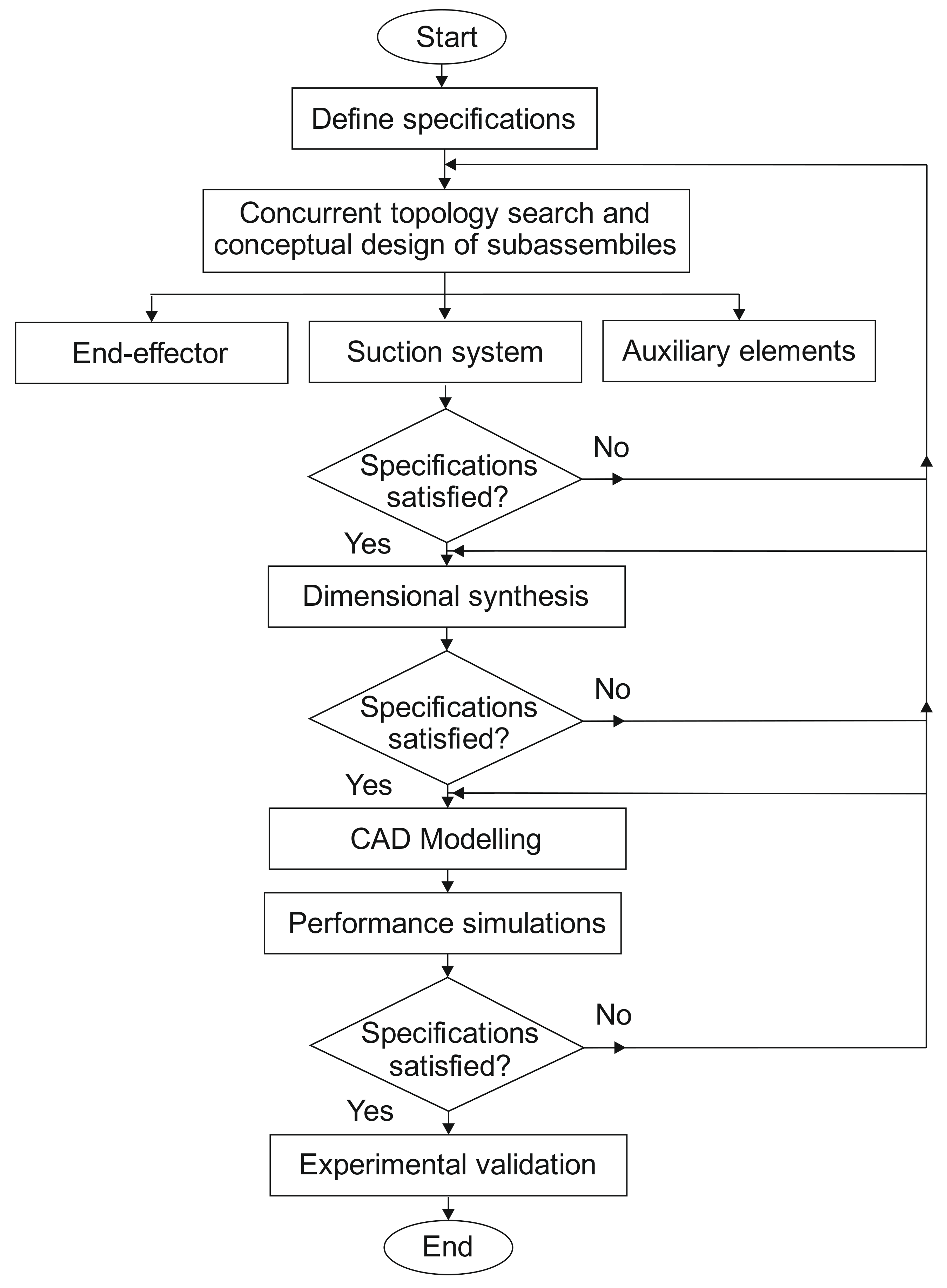
The main design steps are briefly summarized through the following flow-chart in Figure 1, which starts from the definition of the specifications up to the proposed preliminary experimental validation of the proposed device.
3. Conceptual Design
A first step, Table 2 was defined as based on the identified design requirements and constraints. Table 2 can be seen as a first guideline for next design phase. The conceptual design was then performed starting from the data in Table 2 and as a result of design choices that were also closely linked to the analysis of the state of the art. Then, a specific type-synthesis was carried out to identify the main working principles of the proposed device, which can be seen as something conceptually resembling a backpack brush cutter, with a suction element that can resemble a modern garden blower. The entire system can be composed of two distinct units, connected to each other through flexible elements. A first element will have the shape and size suitable to allow the operator to reach the flower without bending the back. At the lower end there will be both the end-effector, which will cut the flower, and the head of the suction system. Through a flexible rubber pipe, the cut flowers will reach the storage area, and both the suction system and the tank can be housed in a backpack-mounted structure, which can not only relieve the operator of the load weighing on the arms but can also make the whole device easily portable. Since the instrument will weigh down entirely on the shoulders and arms of the operator, it has been defined a desired maximum weight of the end-effector lower than 5 kg. The device must also have a fully electric power supply system, which can be powered by a battery to guarantee its autonomy for the entire harvesting phase. Finally, the system must have an average production cost accessible for small and medium-sized enterprises, which are the main producers of saffron.
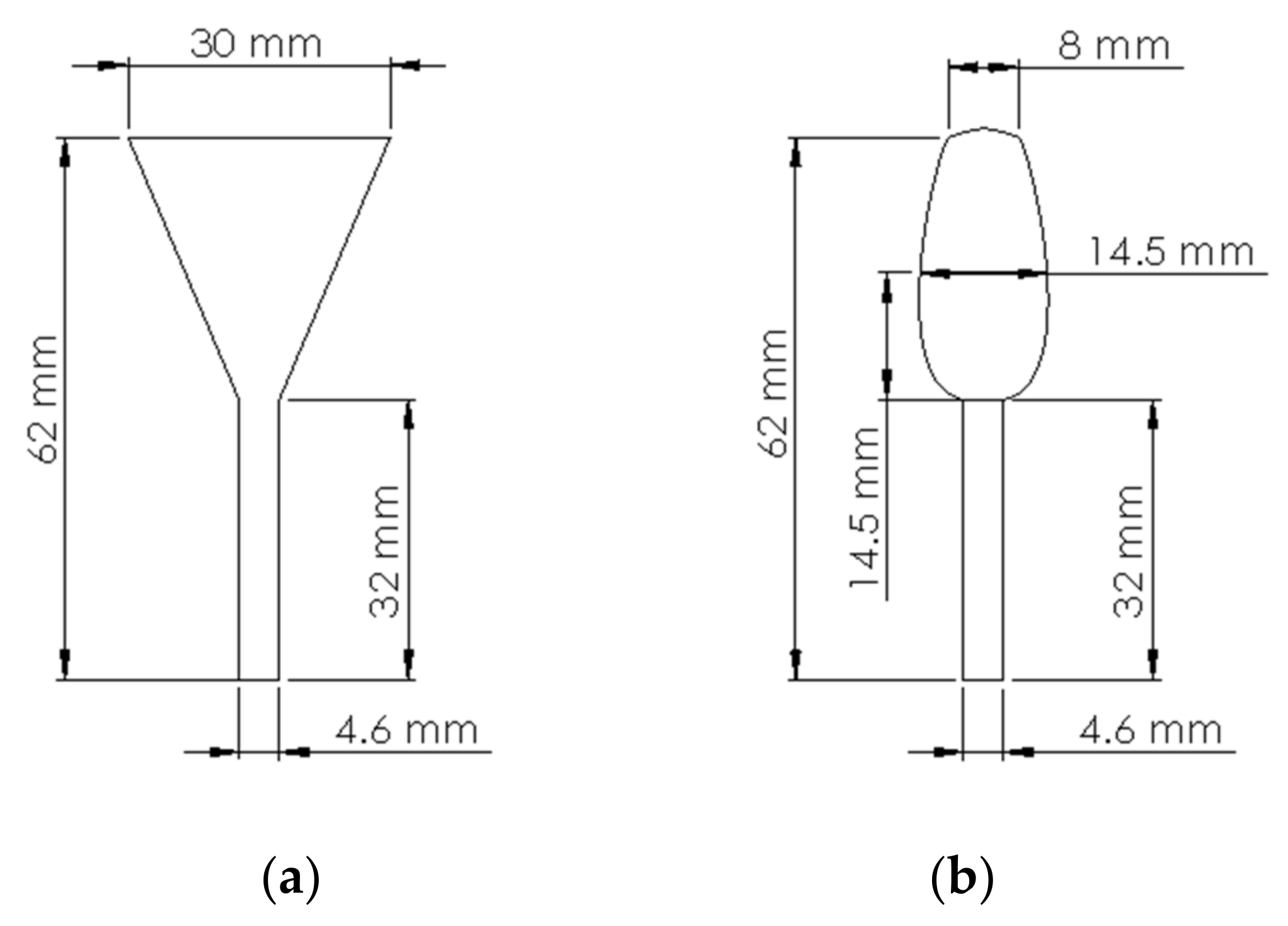
The end-effector shown in [7] can provide useful starting information in terms of design requirements for saffron harvesting. Based on the analysis of this device some key motion features have been identified as the basis for fulfilling the main harvesting and stem detachments tasks. Other allowed motions reported in [7] have been identified as unnecessary. Accordingly, a new concept design has been proposed by defining a novel simple mechanism for achieving the saffron flower harvesting and stem detachment tasks. In the proposed concept, there will be two fingers with a suitably modeled terminal profile, in such a way the two specular surfaces get closer to each other as the two elements are rotated, until, at the last stages of the rotation, they are close enough to guarantee the grasping of the aerial parts of the plant, while avoiding at the same time an excessive tightening which would compromise the integrity of the leaves. Once the rotation movement has been completed a specific traction or bending needs to be applied to achieve the detachment of the flower from the stem. This movement must be properly calibrated, so that the force exerted is sufficient to break the stem of the flower, but at the same time not producing irreversible damage to the leaves. The proposed design solution to achieve this consists of a cam in combination with a leaf spring, which accumulated mechanical energy. The cam can be regulated to set the release of the energy stored in the leaf spring, whose vibration results in the required bending and traction effects on the stem. Similarly, the suction system needs to be adjusted so that the air flow is just sufficient to let the flower float to the storage tank without damage. Consequently, the sizing of the vacuum pumps will be carried out starting from a simplified geometric model of the flower (Figure 2), to estimate its floating speed. Subsequently, once the suction duct has been sized, it will be possible to evaluate the total head losses along the entire path and, therefore, to trace the required pump model.
The tank, in which the collected flowers will be conveyed, will be suitably sized, in such a way as to prevent the flowers from being crushed or broken. It is essential that this is equipped with an opening or unloading system that makes the operation easy.
4. Device Synthesis
The sizing of the gripping elements with the relative handling was carried out. Two mirror fingers are placed at the ends of two transmission shafts by means of two gears having the same module and pitch circumference, to connect a single shaft to the actuation system and to obtain a mirror rotation of the two elements. The overall dimensions of the single finger are defined as the minimum required to hold a small stem of an average saffron flower that are reported in Figure 2.
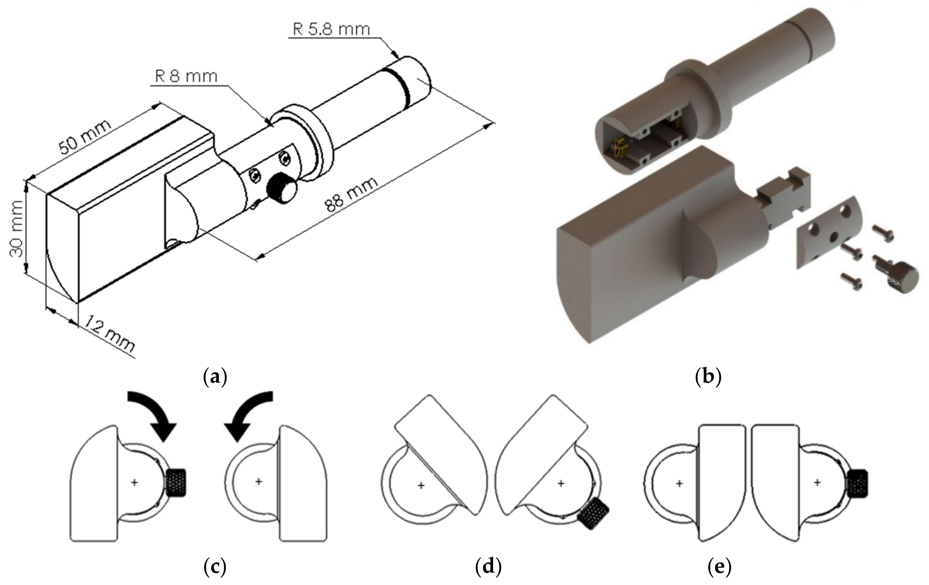
Figure 3 shows the main design features of the proposed two-finger gripper. Note that the surface of the proposed two fingers has been modeled with a round cross-section shape so that the rotation motion allows it to grasp a stem while keeping a minimum distance between the fingers of , as shown in the fully close configuration (Figure 3e). This distance prevents excessive stresses on the stem and can be regulated to fit the average stem diameter, which goes from to , due to cultivation or seasonal/climate parameters. The finger inter-axis distance regulation is achieved by a regulating screw (Figure 3b). The housing for the elements described so far consists of a front element with two holes for the passage of the fingers, and a rear plate with two grooves for the other end of the shafts. The plate has a rotoidal joint on the rear side that is used to create a leaf spring by means of a specifically designed hinge. The leaf spring is made from an aluminum plate that works also as a structural frame element to hold the other components. The design process of this element required careful attention at the sizing of the aluminum sheet thickness, which will have a direct influence on the applicable force values, and consequently on the elastic energy that becomes available in the return phase of the leaf spring movement. More details on the leaf spring design are given in Section 4.3.
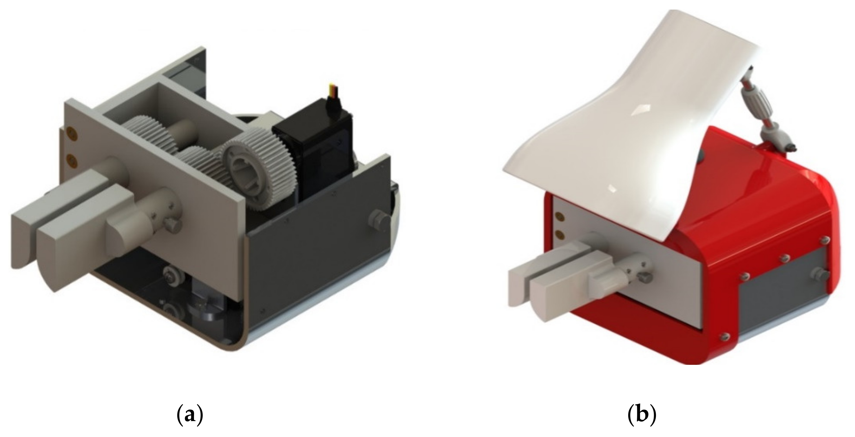
The need to protect the components of the end-effector from the work environment, widely exposed previously, has led to the creation of an external body, once again in plastic material, and essentially composed of two elements, which can be inserted one on top of the other, which will envelop the device with limited additional weight. On the upper side of the body there will be a hole for the cables, equipped with a special gasket to prevent any rainwater or the inevitable earth residues from entering the instrument. In addition to having a protective function, the external body of the end-effector will connect the end-effector to a maneuver rod, which will be made using the rigid section of the suction duct, thus avoiding the redundancy of the structural elements.
The suction head has been modeled as a separate element, connected to the external body by means of a hinge coupling, and positioned exactly above the two finger gripping elements as shown in Figure 4b). On the back side, an adjustable length tie rod has been inserted, connected at one end to the hood itself and at the other to the body of the end-effector. By manually rotating the central body of the tie rod, the operator will be able to adjust the angle between the ground and the maneuvering rod in a range from 30° to 45°.
One should note that the device presented in [7] is completely different from the one proposed in this work. The proposed new device has completely changed the operation paradigm for providing an easily portable fully electric actuation instead of a mixed electric/pneumatic actuation. Also, kinematic design and working principle is different as the new design introduces a cam mechanism and an elastic spring for the detaching of the flowers.
As for the modeling of the suction system we started with the geometry and dimensions of the main elements, such as vacuum pumps and batteries. Terminal velocity of saffron flowers has been estimated through equation of drag force (Equation (1) [22]), where is the drag coefficient, ρ is the air density ( in standard condition) and is the surface that the flower expose to airflow, considering as a critical condition the situation in which the weight force of a single flower equals the aerodynamic resistance [23].
The worst condition is represented by the closed flowers, as these expose a smaller surface to the airflow. Then, surface value has been evaluated from Figure 2 data, while drag coefficient of closed flower, equal to , has been identified from literature [22]. Terminal velocity has been found at about , for a flower of an average weight of 1 g. The air flow is overestimated to achieve a force ranging from 2 to 4 times the gravity force of a flower and considering an intake duct with a diameter of . To guarantee the above conditions, the vacuum pump must provide a flow rate of , which can be achieved with commercial devices.
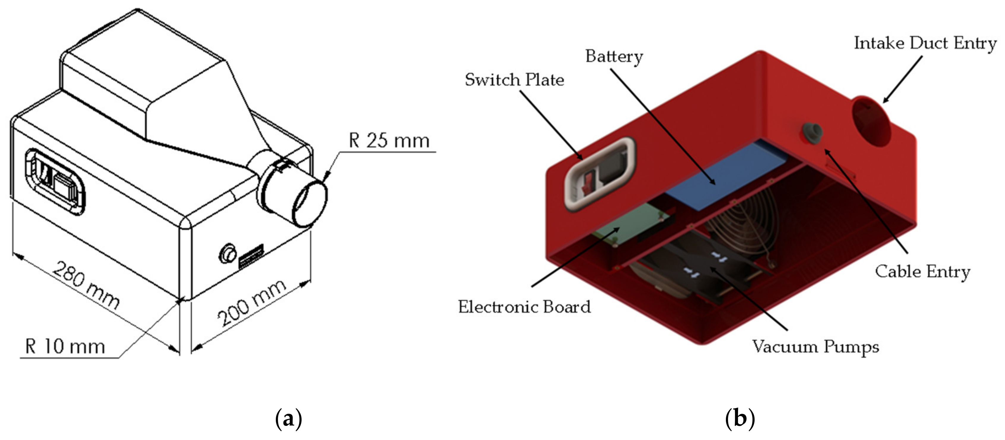
The total manometric head required by the pump was estimated by considering the geometry of the CAD model and the average height of the shoulders of an operator (about ). The approximate value, useful for a first estimate of the power required by the pump, is . A suitable commercial pump can be identified through online catalogues, such as the G1238B24BBZP-00 axial vacuum pump of Nidec Servo Corporation. Essentially, the suction system can be considered to be composed of two distinct bodies: a head, inside which all the electronic elements will be assembled, as well as the outlet of the suction duct, and a storage compartment, which will represent the real tank of the system under consideration, with a capacity of 14 liters. The two elements, which can be easily assembled by means of two toggle closures, will form the entire shoulder-mounted structure as schematically shown in Figure 5.
The battery pack must be able to power a total of two servomotors, which require approximately input, and two vacuum pumps, which instead require a power supply voltage of . The battery power capacity must be sufficient to ensure autonomy ranging from 3 to 6 h. For the purpose, a commercial Li-ion battery pack has been identified with an output voltage of and power capacity of .
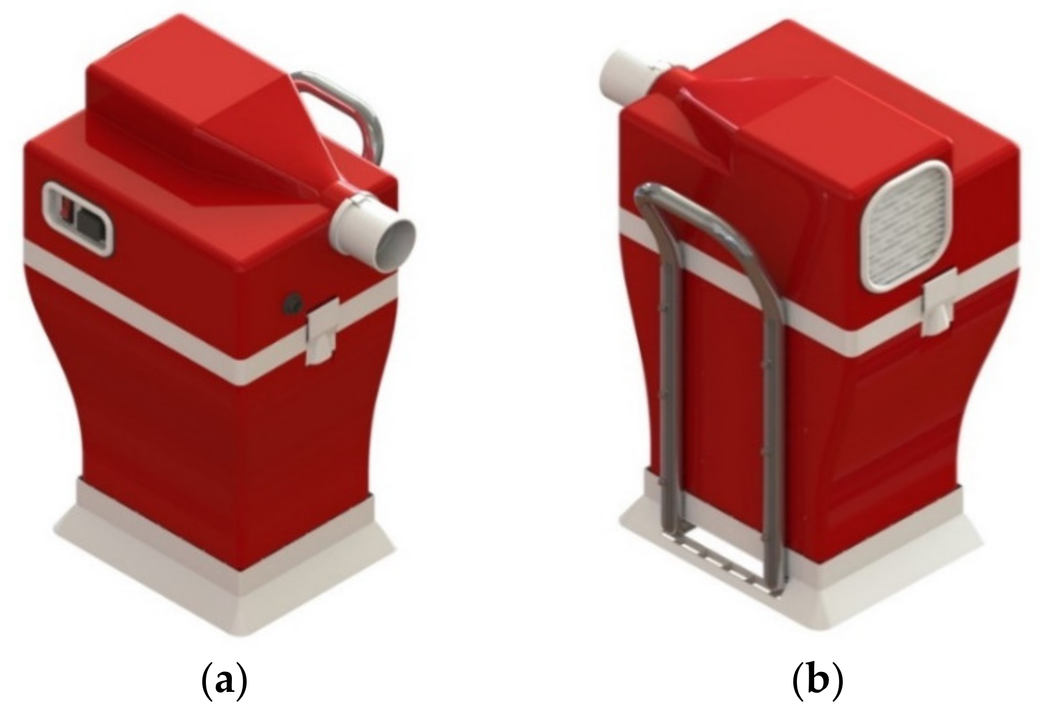
A small platform has been inserted at the base of the storage unit, which in addition to increasing the stability of the structure on surfaces such as the soil of the cultivation fields, allows direct contact to be avoided between the soil and the tank. On the back of the tank, through screw connections, an aluminum tube has been inserted, as outlined in Figure 6. The usefulness of this element lies, in addition to increasing the entire stiffness of the backpack and facilitating the assembly of the platform, in allowing the attachment of the harness which will then wrap around the operator’s shoulders, allowing to carry the instrument without engaging your hands.
One should note that this paper is mostly focused on the design of a proof-of-concept prototype where a first feasible engineering solution is identified. It is important to point out that such a design has been also carefully considering safety aspects including electric safety. and mechanical safety. Accordingly, the proposed device only uses low-voltage direct current (DC), which prevents risks of fulguration. Furthermore, electronic components have been isolated and protected against dust and humidity. Mechanical safety has been carefully considered so that human body and operator dresses cannot fit into any moving mechanical part. Also, torque limits are set to prevent any risk of mechanical injuries even in the unlikely event of hitting human limbs or soft tissues.
A further systematic analysis of safety aspects will be handled at the industrialization stage by considering, among other standards the European Standard EN ISO 13482 and any other legal requirements for CE marking. The Conformitè Europëenne (CE) Mark is defined as the European Union’s (EU) mandatory conformity marking for regulating the goods sold within the European Economic Area (EEA) since 1985. Also impact tests could be performed to assess safety, as proposed for example in [24].
4.1. Motor Sizing
The first servomotor performs the rotation of the fingers. It can be sized by considering a free body scheme with a rotation equilibrium as proposed in textbooks such as [25]. This allows the following equilibrium equation:
where is the driving torque, is the friction torque and is the moment of inertia. The only resistive forces will be friction and inertia of the involved mechanical elements. However, both friction and inertia are very small and can be considered as negligible in this specific case. Based on this assumption the size of the first servomotor can be set as equal to the second servomotor. Indeed, this choice has several practical advantages, including a simpler modular control hardware architecture. The second servomotor actuates the leaf spring motion by means of a cam system and a pulling cable. For the second servomotor sizing, it will be necessary to refer to the input force value on the leaf spring that was defined at the leaf spring design stage as equal to . Then, the radius of the pinion has been set at for achieving a compact design. This radius value leads to a required torque equal to . A suitable commercial servomotor was selected from available online catalogs as the Longruner LDX 218 QY10. This servomotor provides a maximum torque of , and requires power supply voltage ranging from to . As previously mentioned, the system will be equipped with two identical servomotors for driving both the fingers and the leaf spring.
4.2. Gears Sizing
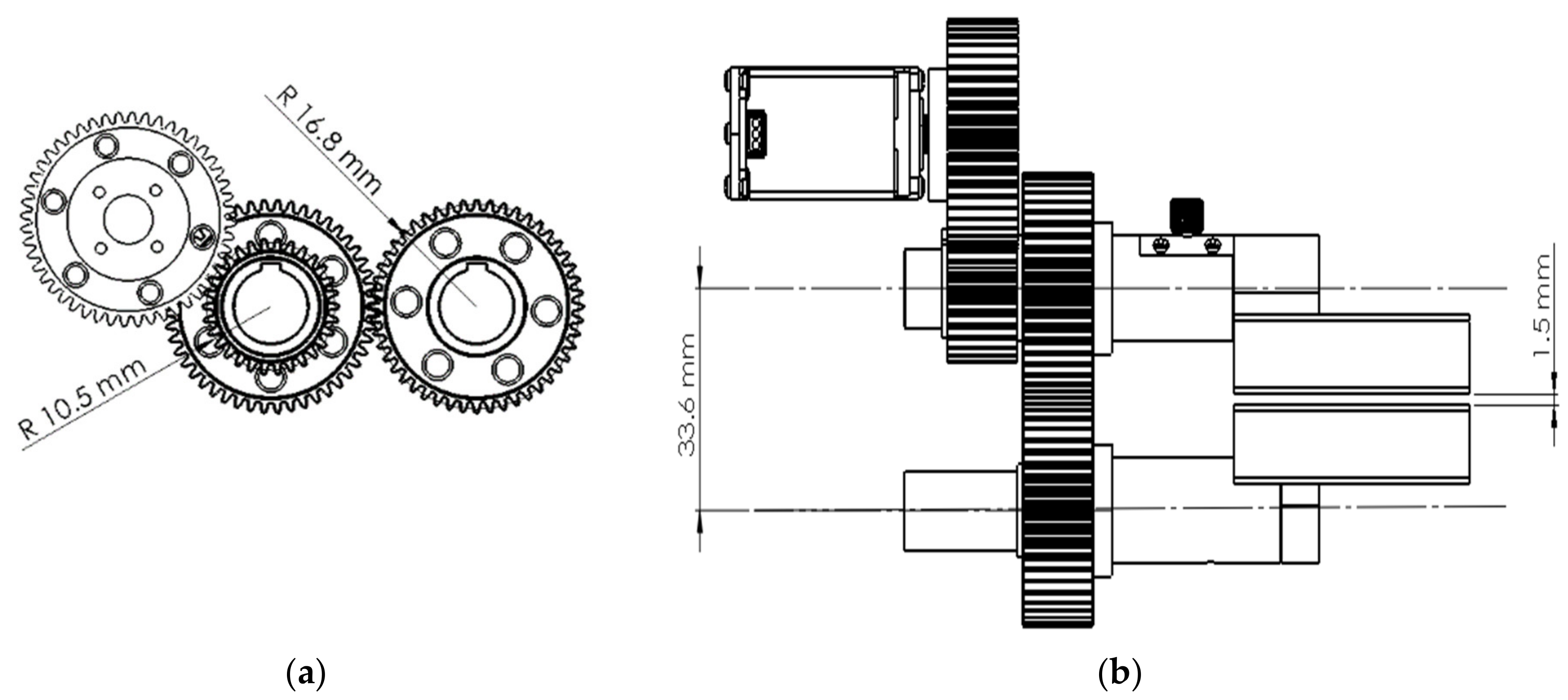
Starting from the dimensions of the gripping elements, and considering the data relating to the minimum distance that must be maintained between the two gripping surfaces (), it was possible to proceed with the sizing of the transmission system in Figure 7.
The distance between the central axis of the two shafts must be equal to , and this leads us to define the primitive radius of the two mirror gears, equal to . Two gears with a number of teeth and module respectively equal to 48 and 0.7 were chosen. Having decided to use a servomotor for the movement of the fingers and considering its the operation over a 180° arc as a data plate, to avoid positioning errors or too long times, it was decided to insert an additional gear that would allow to obtain a transmission ratio between shaft and motor. This additional toothed wheel, of the same module as the previous ones, will have a primitive radius of , and a number of teeth equal to , and will also be integral with one of the two transmission shafts. The pinion connected directly to the servomotor will act on this last element and consists of a toothed wheel that is identical in parameters to the two gears with a larger diameter, but having a different connection shape. In this way it will be possible to limit the maximum rotation of the servomotor to an arc of 112.5°, resulting in an output rotation of 180° on the two fingers.
4.3. Cam and Leaf Springs Design
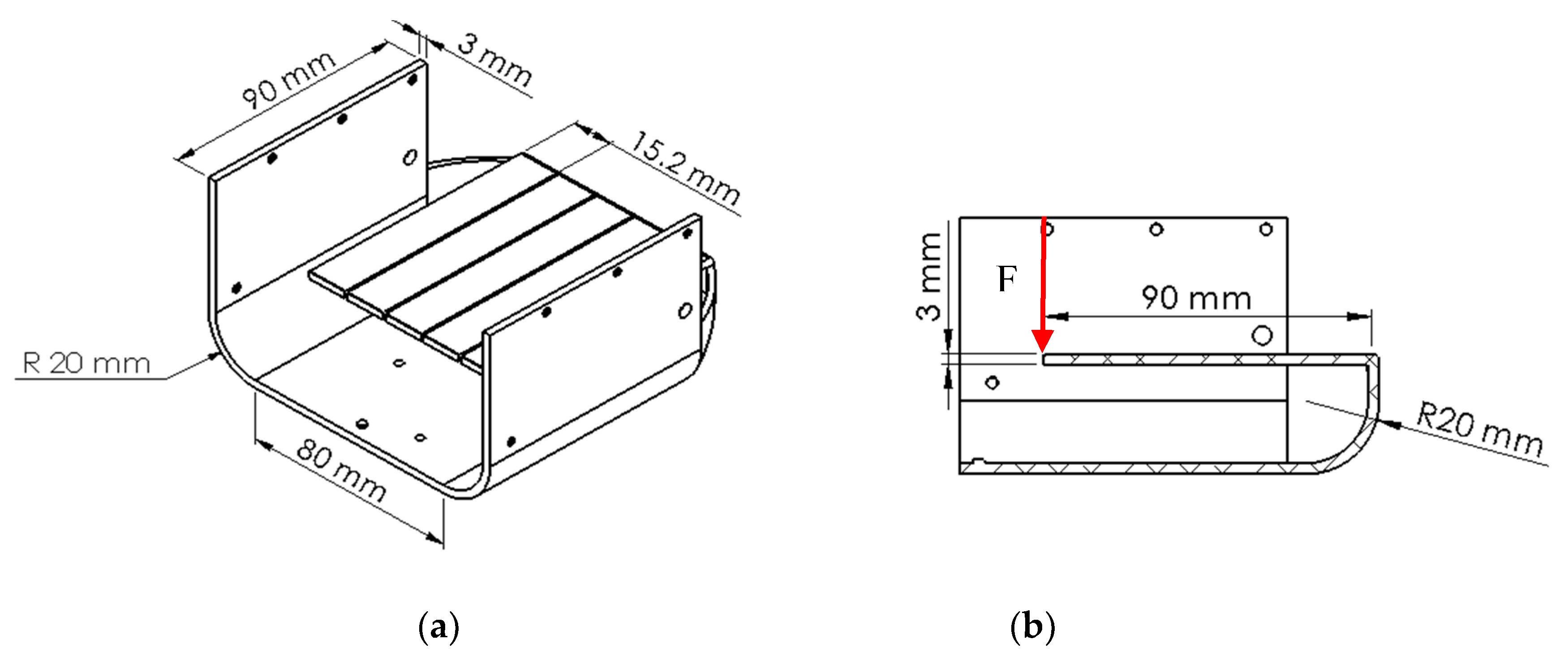
To proceed with the sizing of the leaf springs, a loading force for the leaf spring was set as equal to This value was sufficient to produce a compliant displacement of on the free end of the leaf spring. To reduce footprint size several leaf springs were arranged in parallel.
From definition of stiffness of the bent beam, as reported for example in [26], one can write:
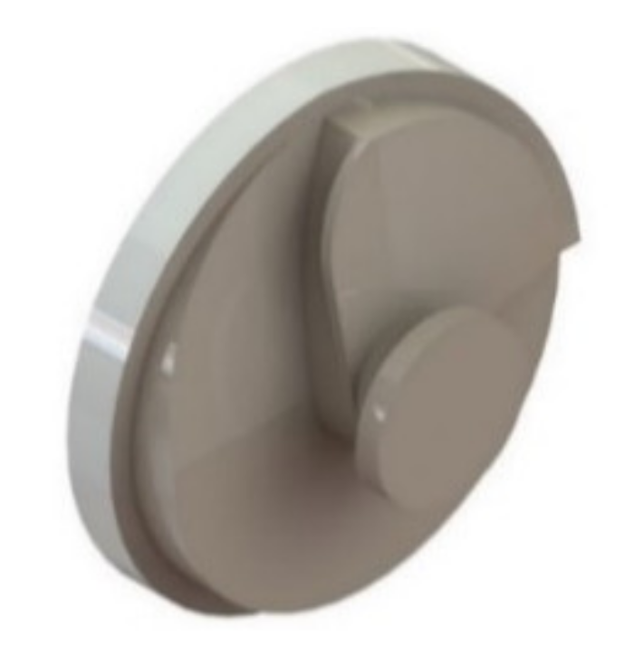
where n is the number of parallel leaf springs, E is the Young module, I is the static moment of inertia, L is the beam length and y is the compliant displacement along y direction. An iterative calculation spreadsheet was implemented to identify the most convenient value of . This value has been obtained by considering E = 69,000 for a standard aluminum alloy, values I and L have been based on an aluminum plate with geometric dimensions equal to 3.0 by 5.2 by 90.0 mm. Considering the results obtained, the whole case and leaf spring design was completed as detailed in Figure 8. The bending of the leaf spring was obtained by applying a pulling force at its free end. This was achieved by means of a nylon thread, through an innovative cam system specifically designed for this purpose as reported in Figure 9 and Figure 10.
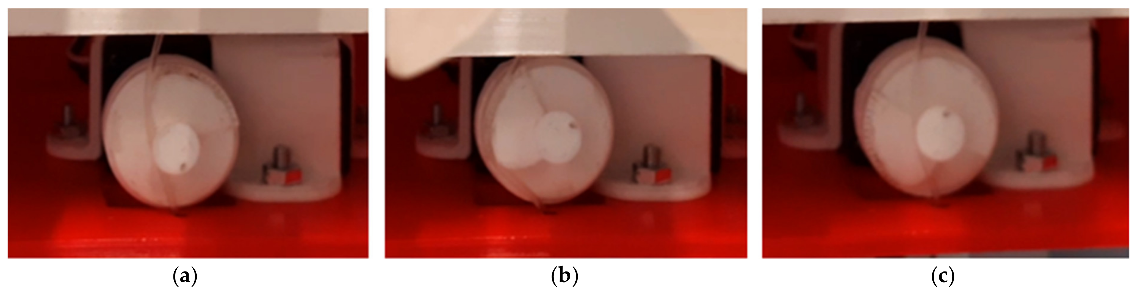
With this solution, one end of the nylon thread will be connected to the main plate of the gripper block, while the other will be rigidly connected to the structural case. In this way the wire, which at rest will be in a vertical position, will always have its axis tangent to the profile of the cam. The cam has been modeled in such a way that a first counterclockwise rotation of the cam of will put the wire in traction, then allowing its instantaneous release after a further rotation. The cam rotation and the two fingers motion are synchronized so that the release of the leaf spring is achieved when the two fingers are in the fully close configuration allowing the required detachment of the stem only after holding firmly a saffron flower. After this phase, the cam continues its rotation to automatically reload the leaf spring for the next operation while the fingers go back to the fully open configuration.
5. Rapid Prototyping of the End-Effector
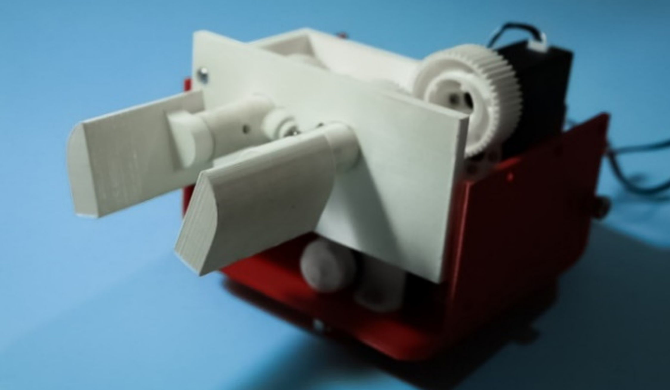
Starting from the CAD models created during the design phase, a prototype of the end-effector was created, using the 3D printing technique. As a raw material, polylactic acid (PLA) was selected. Most other components such as servomotors, raw aluminum plates or connection systems such as screws, nuts and inserts were selected as off-the-shelf. Once all the necessary elements were available, the assembly was completed, thus obtaining a proof-of concept prototype as shown in Figure 11.
6. Preliminary Experimental Tests
Several preliminary laboratory tests were carried out. A first session of tests focused on setting up all the operation parameters of the device. In particular, the successful operation of the proposed devices required a careful set up of the minimum inter axis distance between the fingers. Indeed, a small value of this parameter proved fundamental for achieving a successful harvesting of saffron flowers while too small values can generate excessive mechanical stresses to the stem. Accordingly, the most convenient tradeoff value was experimentally identified according to the specific stem sizes of the flower to be harvested.
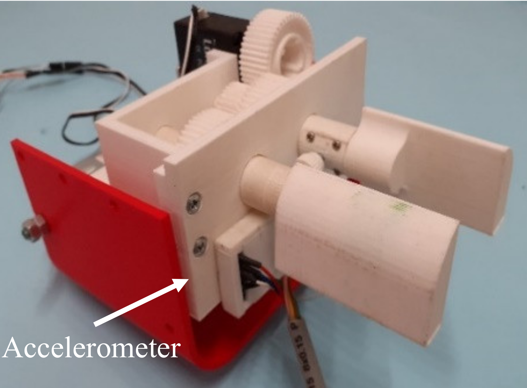
Further experimental tests were carried out by using an accelerometer FXLN8371Q analog triaxial accelerometer, manufactured by Freescale Semiconductor, Inc., with a selected sensitivity range of ±2 g. This accelerometer was selected due to its low-cost and user-friendly implementation for data acquisition with an Arduino® board. The sensor was placed near the two fingers on the prototype as shown in Figure 12. This specific position allowed the accelerations along X- and Y-axes lying on the plane parallel to the front structural plate to be measured, with the Z-axis being coaxial with the fingers. In this configuration, the gravitational acceleration will be detected through negative values, with components along Y- and Z-axes. Note that gravity accelerations are exactly equal to -g only when the Y-axis is aligned perfectly along vertical direction.
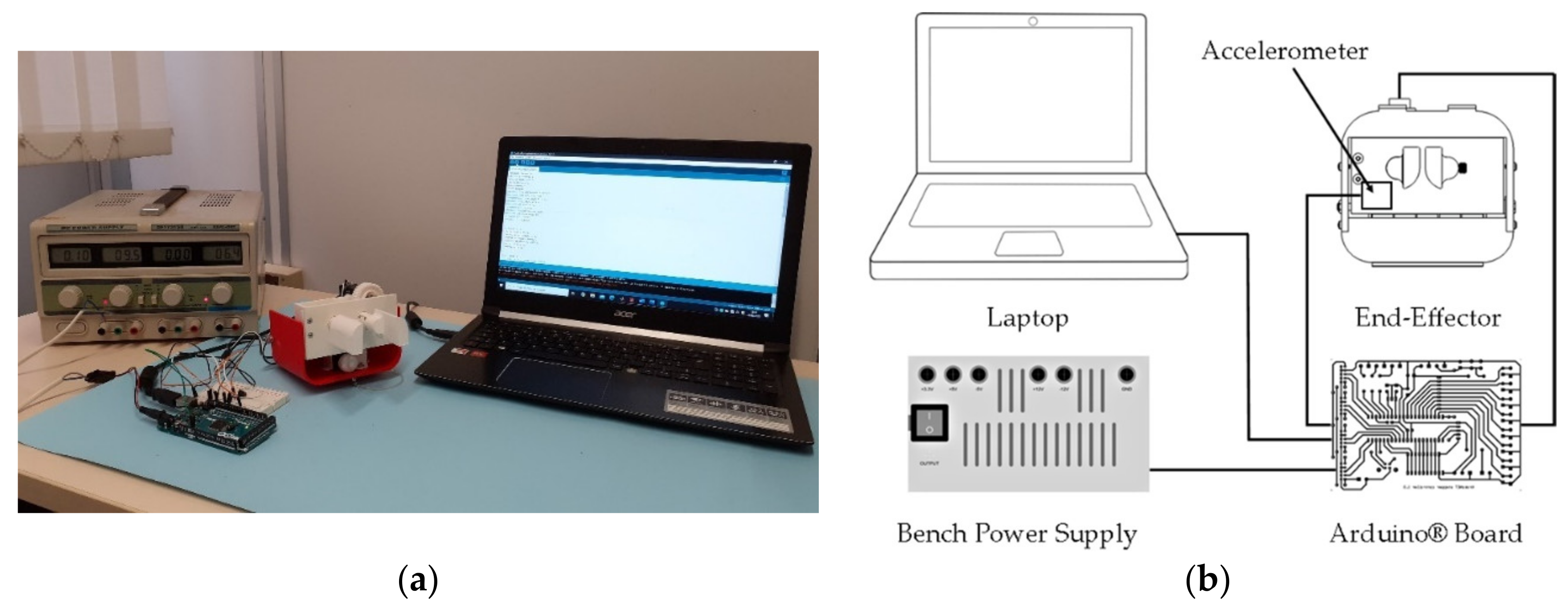
The electronic management of the accelerometer was achieved by using an Arduino® board as shown in the experimentation setup in Figure 13. The Arduino® board was integrated to manage the two servomotors on the device and the accelerometer. Accelerometer data sampling was set at of 0.005 s intervals.
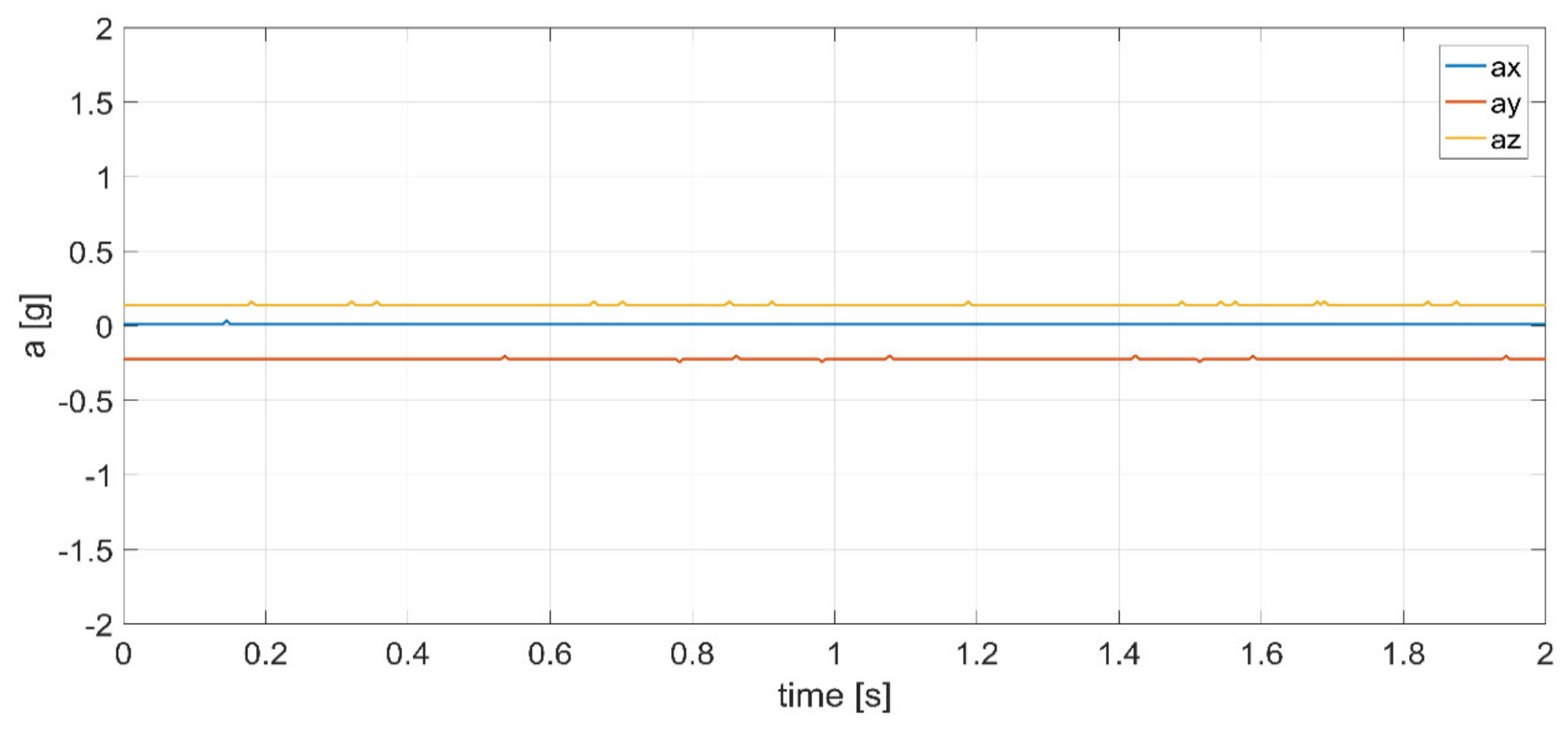
The first measurements have been carried out without making the end-effector perform any movement. Experimental results are shown in the plot of Figure 14 in terms of accelerations along X-, Y-, and Z-directions versus time. This allows to calibrate the sensor and remove any offset due to gravity and mounting conditions.
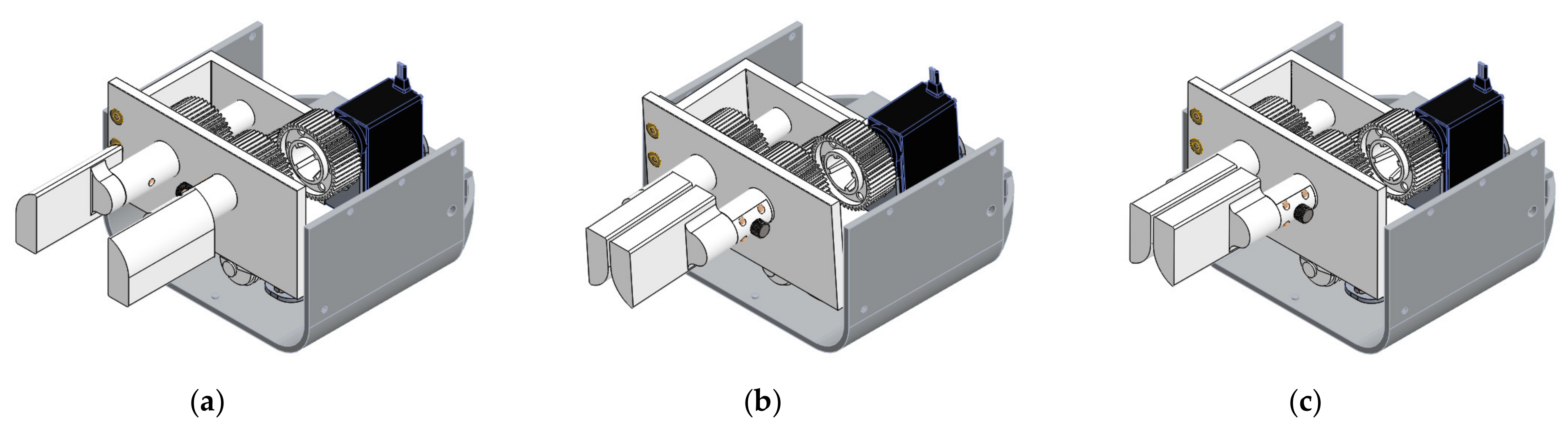
A further set of experimental tests was carried out with the end-effector standing on a laboratory desk while operation the two servomotors. The results obtained show the vibration effects due to the servomotors operation. For an easier interpretation of the experimental data, numerical simulations of the same operation condition were obtained within Solidworks® Motion simulation environment. Simulation data were obtained through a motion study in Solidworks® environment on a simplified 3D CAD model of the proposed device, as reported in Figure 15. The traction wire force was simulated by applying a load of 50 N on the upper surface of the front plate of the gripping module, while the leaf spring reaction was modeled through a compression spring below the gripping module. The software allowed the extraction of acceleration data of specific point, which correspond to the data collected by the accelerometer on the prototype.
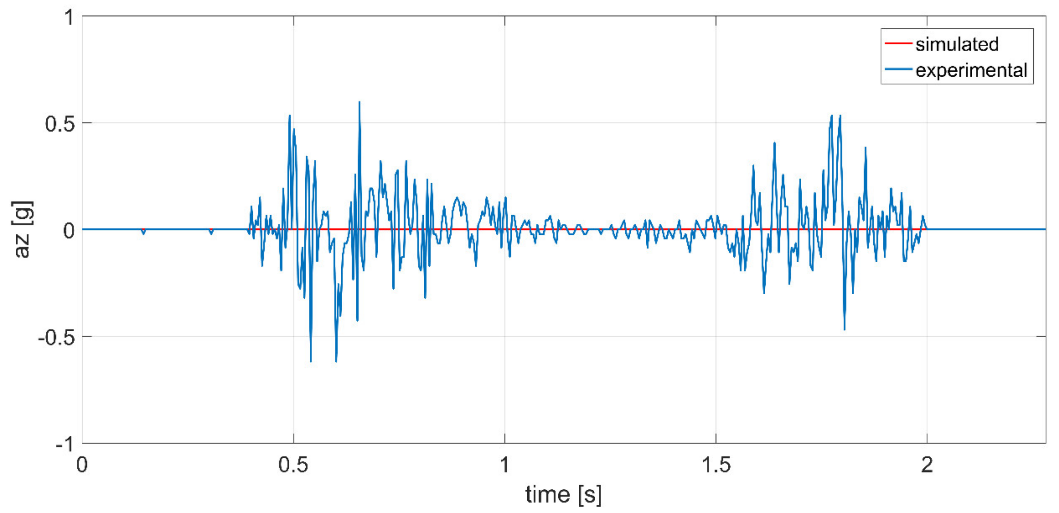
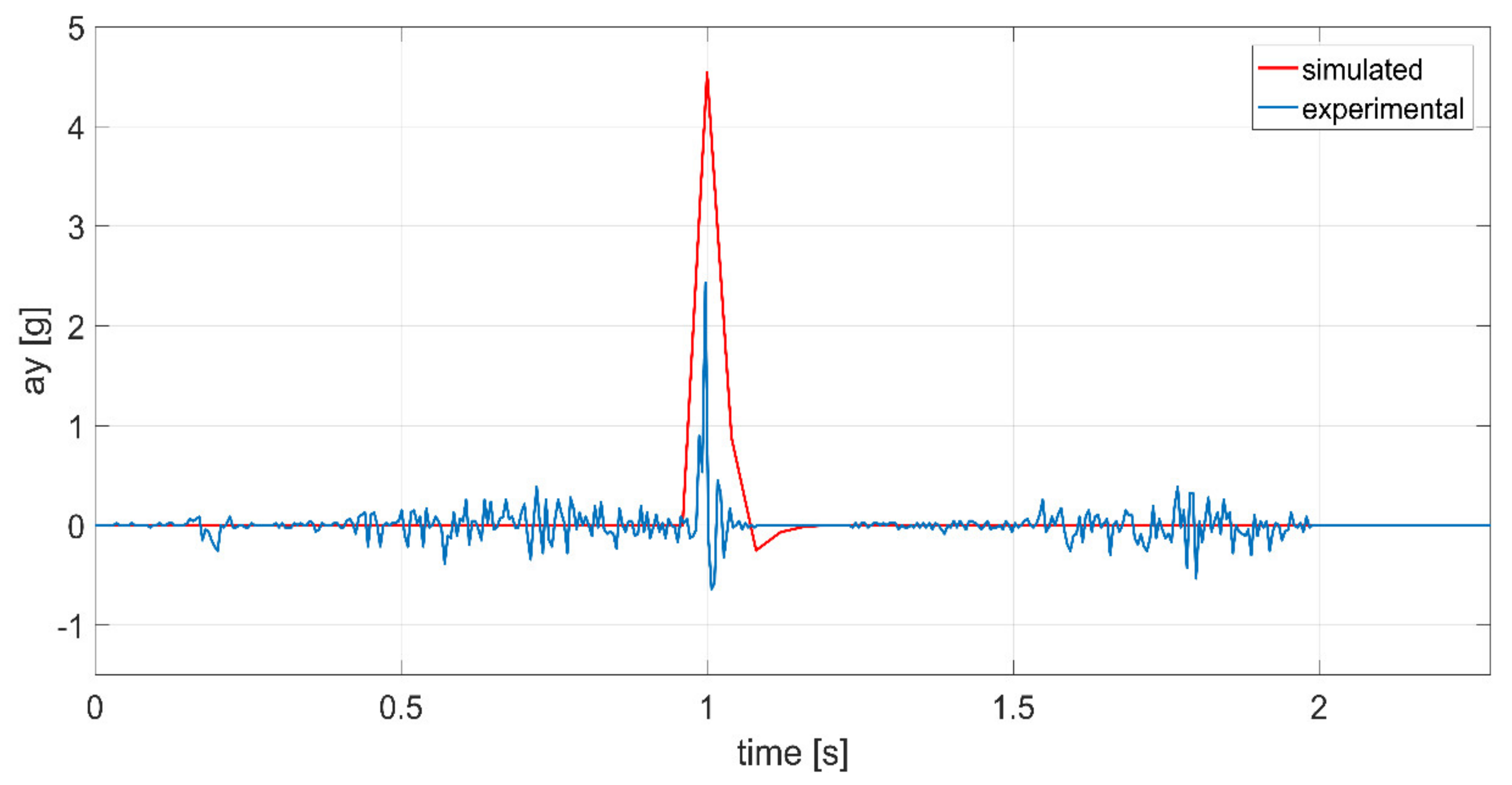
The data obtained are shown in the plots of Figure 16, Figure 17 and Figure 18 with a comparison of both numerical simulations and experimental results. Note that experimental data show an oscillatory trend, when the two servomotors were in operation, which is not evident in the numerical simulations. This is mostly due to the servomotors and gearboxes own vibrations that are not considered in the simulation model. Looking at the accelerations along X-axis (Figure 16), one can identify mostly the vibrations introduced by the servomotors and transmissions. The acceleration remains close to the null value when no element is in motion. There are two evident oscillatory trends in two distinct intervals, which corresponds to the servomotors operation. The same effect is visible in the trends detected on the accelerations along the Y-axis and Z-axis in Figure 17 and Figure 18, respectively.
Observing Figure 17, one can identify an acceleration peak in both theoretical and experimental data. This peak is representative of the instant in which the cam releases the traction wire, allowing the leaf spring to release its energy with a sudden upward motion. This effect can be seen clearly in the plots of Figure 18 where one can identify the release of the traction wire with the consequent activation of the leaf spring followed by a sudden acceleration of the fingers. The acceleration peak clearly shows the instant in which the gripping elements effectively cut the stem of the flowers. The high acceleration value is linked to the success of the operation, and it is representative of the correct calibration of the bending system. In the simulated data the peak acceleration reaches the value of 4.5 g, while in experimental line the peak just exceeds the value of 2 g. This is due to the approximations introduced in the simulation model where, in particular, the joint clearances are not modeled.
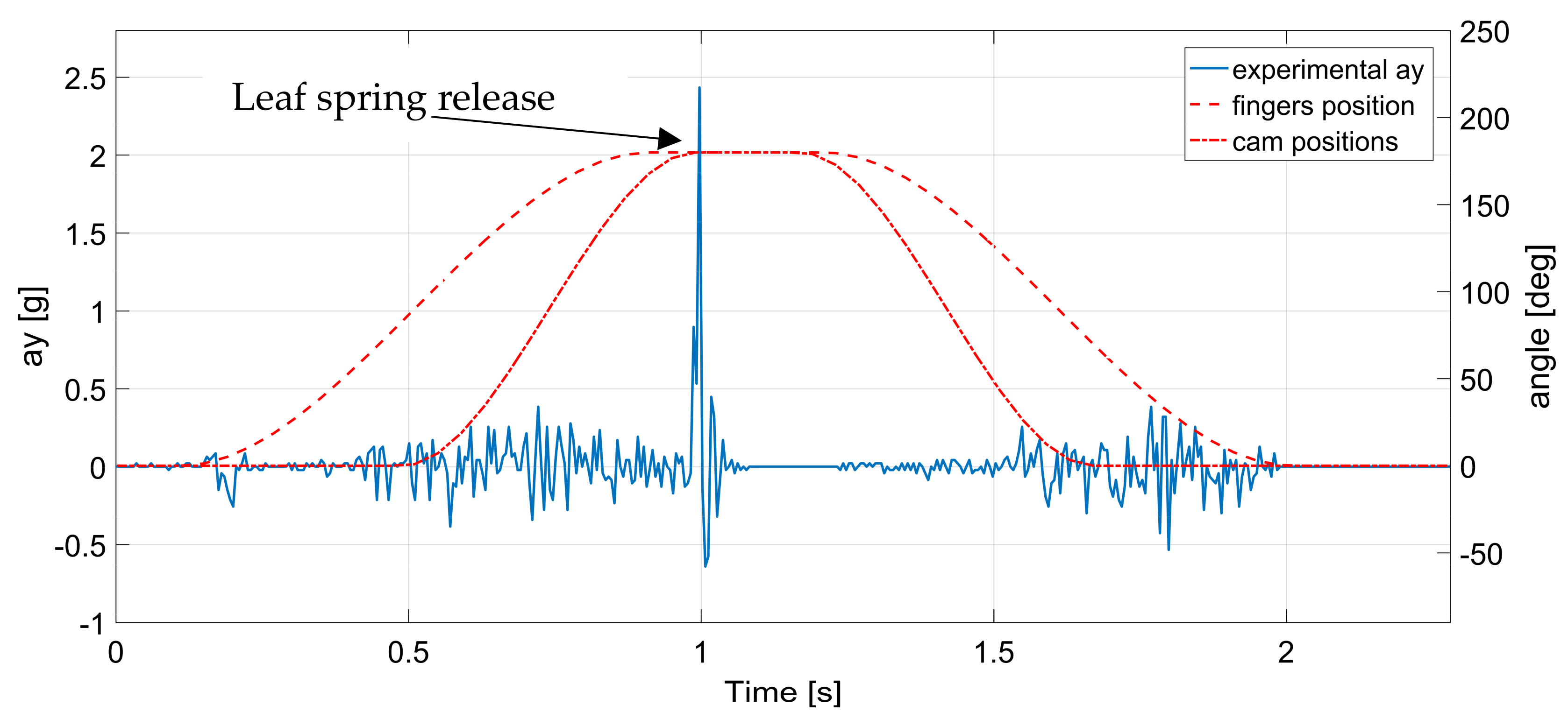
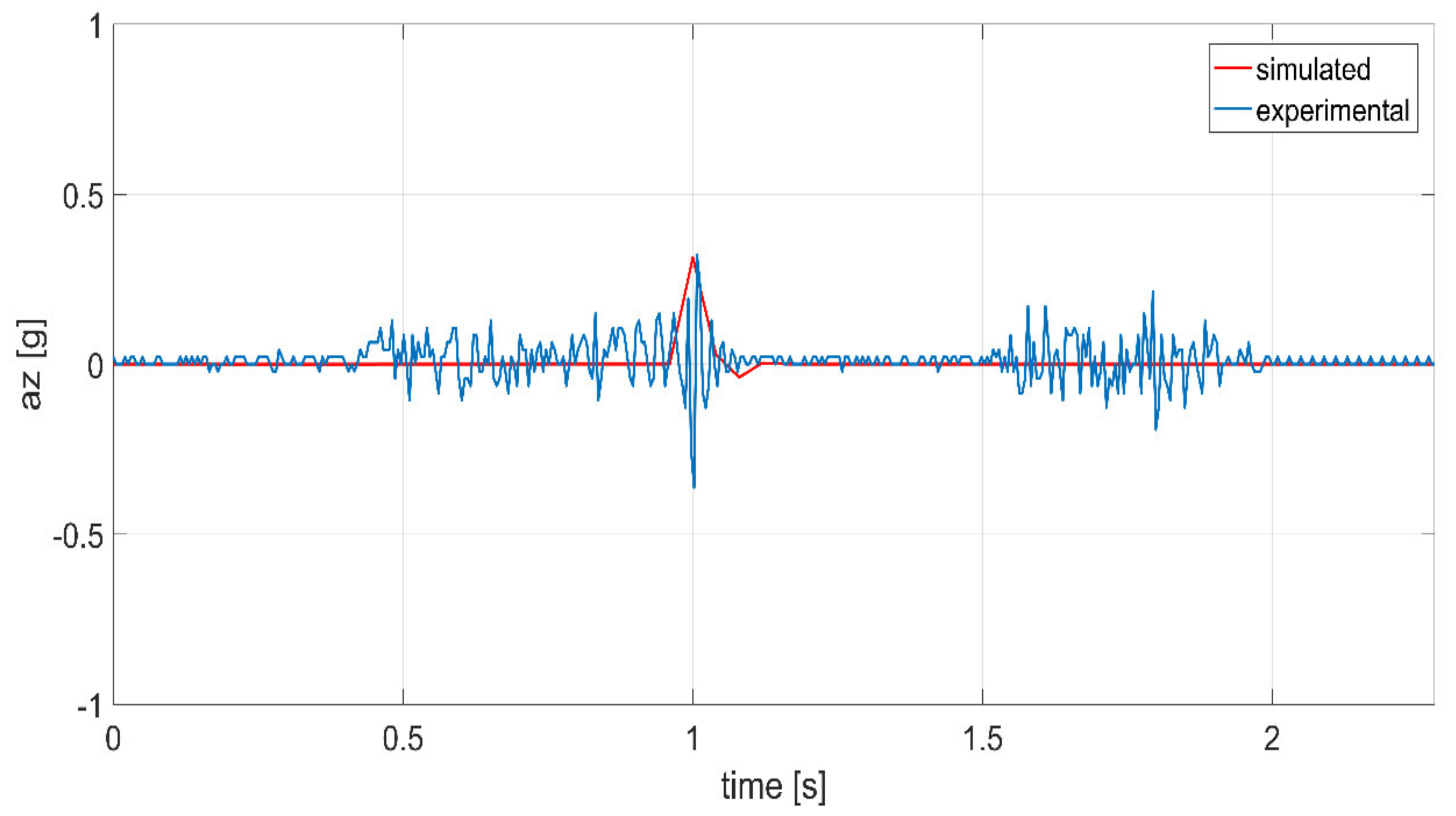
Figure 19 shows the accelerations along the Z-axis. Similarly, on Y-axis it is possible to observe a slight acceleration peak at the instant in which the wire is activated (Figure 19) in both simulated and experimental data. In particular, in the experimental data one can identify a first negative peak followed by the maximum positive acceleration peak with a value of about 2.5 g. This is due to the change in orientation that the gripping element performs with respect to the Z-axis. When the cam releases the traction wire, the plane parallel to the surface of the gripping system starts its movement from a negative inclination with respect to the horizontal plane and it ends its motion with a positive inclination angle. This explains the sign change in the acceleration peak value. Note that the initial negative inclination of the surface is not fully modeled in the simulations where a fully horizontal starting configuration is assumed. This effect is a source of offset between numerical and experimental data.
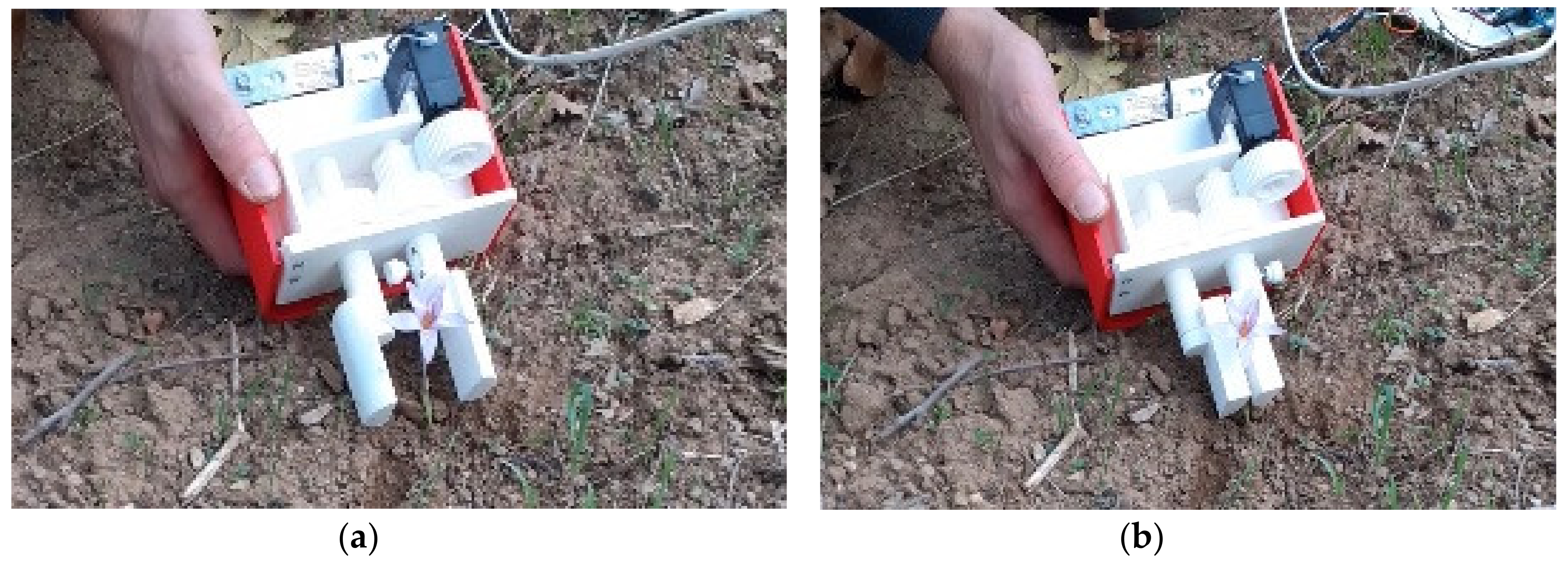
Finally, field tests were performed on wild saffron flowers as shown in Figure 20. Unfortunately, field tests can be performed only during few weeks and are limited by the seasonal blossoming of wild saffron flowers. Although preliminary the field tests demonstrated the effectiveness of the proposed harvesting principle. A further design optimization process should be planned for achieving optimized specifications and features as compared with the current proof-of-concept laboratory prototype.
Further activities will be planned in future to address other aspects such as, for example, the stigma separation, as reported in [23]. Also, further careful attention will be given to improving the prototype design, also as based on other topologies, or grasping strategies as proposed for example in [27,28,29,30], while we believe the results obtained fulfilled the aim of this work consisting in identifying a novel concept design and reporting a proof-of-concept prototype to demonstrate the feasibility of the proposed concept. In the future, we will consider also performing a design optimization with a systematic approach such as that one proposed, for example, in [31,32,33,34,35].
7. Conclusions
This paper addresses the design of a semi-automatic system for saffron flower harvesting. In particular, this paper proposes a conceptual design of a specific mechanism for the harvesting, stem detachment, and collection of saffron flowers in a storage tank by using air flow. Specific attention has been addressed to the design of a novel two-finger gripper in combination with a specific transmission system of a leaf spring and a cam that allow a gentle detachment of the saffron flower from the stem. The proposed design has been engineered towards a proof-of concept prototype by using rapid prototyping and off-the-shelf components. Numerical simulations and preliminary experimental tests have been carried out. Both numerical and experimental results demonstrate the engineering feasibility and effectiveness of the proposed harvesting strategy. Future work will include further field tests as well as a systematic optimization of the proposed design.
8. Patents
An Italian patent has been submitted for the proposed mechatronic device [36].
Author Contributions
Conceptualization, A.R.D. and G.C.; methodology, A.R.D. and G.C.; software, A.R.D.; analysis and validation, A.R.D. and G.C.; writing, A.R.D. and G.C.; review and editing, A.R.D. and G.C.; supervision, G.C. and A.M.B. All authors have read and agreed to the published version of the manuscript.
Funding
This research received no external funding.
Data Availability Statement
The data presented in this study are available on request from the corresponding author. The data are not publicly available due to intellectual property protection.
Conflicts of Interest
The authors declare no conflict of interest.
References
- Alonso Diaz-Marta, G.L.; Arghittu, A.; Astrka, K.; Betza, T.; Cambae; Conada Sanchez, M.; Cilloco, M.T.; Corona, G.; Curreli, M.; Deferera, D.; et al. White Book Saffron in Europe Problems and Strategies for Improving the Quality and Strengthen Competitiveness; INTERREG IIIC. 2006. Available online: https://www.researchgate.net/publication/269709026_White_Book_Saffron_in_Europe_Problems_and_Strategies_for_improving_the_quality_and_strengthen_competitiveness (accessed on 7 May 2021).
- Ruggiu, M.; Bertetto, A.M.A. Mechanical Device for Harvesting Crocus Sativus (Saffron) Flowers. Appl. Eng. Agric. 2006, 22, 491–498. [Google Scholar] [CrossRef]
- Antonelli, M.G.; Auriti, L.; Beomonte Zobel, P.; Raparelli, T. Development of a New Harvesting Module for Saffron Flower Detachment. Rom. Rev. Precis. Mech. Opt. Mechatron. 2011, 39, 163–168. [Google Scholar]
- Manuello Bertetto, A.; Ricciu, R. Mechanization in Harvesting Saffron: An Opportunity for Economic Development in Sardinia. In Proceedings of the Advances in Business-Related Scientific Research Conference, Olbia, Italy, 5–7 September 2012. [Google Scholar]
- Asimopoulos, N.; Parisses, C.; Smyrnaios, A.; Germanidis, N. Autonomous Vehicle for Saffron Harvesting. Procedia Technol. 2013, 8, 175–182. [Google Scholar] [CrossRef] [Green Version]
- Gambella, F.; Paschino, F.; Manuello Bertetto, A. Perspective in the Mechanization of Saffron (Crocus sativus L.). Int. J. Mech. Control 2013, 14, 3–8. [Google Scholar]
- Manuello Bertetto, A.; Ricciu, R.; Badas, M.G. A Mechanical Saffron Flower Harvesting System. Meccanica 2014, 49, 2785–2796. [Google Scholar] [CrossRef]
- Russo, M.; Ceccarelli, M.; Corves, B.; Hüsing, M.; Lorenz, M.; Cafolla, D.; Carbone, G. Design and Test of a Gripper Prototype for Horticulture Products. Rob. Comput. Integr. Manuf. 2017, 44, 266–275. [Google Scholar] [CrossRef]
- Backman, J.; Oksanen, T.; Visala, A. Navigation System for Agricultural Machines: Nonlinear Model Predictive Path Tracking. Comput. Electron. Agric. 2012, 82, 32–43. [Google Scholar] [CrossRef]
- Zappatore, G.A.; Reina, G.; Messina, A. Analysis of Highly Underactuated Robotic Hand. Int. J. Mech. Control 2017, 18, 17–23. [Google Scholar]
- Espinosa-García, F.J.; Arias-Montiel, M.; Ceccarelli, M.; Carbone, G.; Lugo-Gonzales, E. Design and Experimental Characterization of a Novel Subactuated Mechanism for Robotic Finger and Movable Palm. Int. J. Mech. Control 2019, 20, 141–146. [Google Scholar]
- Yan, W.; Deng, Z.; Chen, J.; Nie, H.; Zhang, J. Precision Grasp Planning for Multi-Finger Hand to Grasp Unknow Objects. Robotica 2019, 37, 1415–1437. [Google Scholar] [CrossRef]
- Robson, N.; Ghosh, S.; Soh, G.S. Kinematic Synthesis and Design of the Robust Closed Loop Articulated Minimally Actuated (CLAM) Hand. Robotica 2020, 38, 1921–1939. [Google Scholar] [CrossRef]
- Marwan, Q.M.; Chua, S.C.; Kwek, L.C. Comprehensive Review on Reaching and Grasping of Objects in Robotics. Robotica 2021, 1–34. [Google Scholar] [CrossRef]
- Kondo, N.; Monta, M. Fruit Harvesting Robotics. J. Robot. Mechatron. 1999, 11, 321–325. [Google Scholar] [CrossRef]
- Rosier, J.C.; Snel, R.; Goedvolk, E.J. Automated Harvesting of Flowers and Cuttings. In Proceedings of the International Conference on Systems, Man and Cybernetics. Information Intelligence and Systems, Beijing, China, 14–17 October 1996. [Google Scholar]
- Rodríguez, F.; Moreno, J.C.; Sánchez, J.A.; Berenguel, M. Grasping in Agriculture: State-of-the-Art and Main Characteristics. Grasping in Robotics; Springer: London, UK, 2013; pp. 385–409. [Google Scholar]
- Kapach, K.; Barnea, E.; Mainor, R.; Edan, Y.; Ben-Shaha, O. Computer Vision for Fruit and Harvesting Robots: State of the Art and Challenges Ahead. Int. J. Comput. Vis. Robot. 2012, 3. [Google Scholar] [CrossRef] [Green Version]
- Li, Z.G.; Liu, Z.; Li, P.P. Study on the Collision Mechanical Properties of Tomatoes Gripped by Harvesting Robot. Afr. J. Biotechnol. 2009, 8, 7000–7007. [Google Scholar]
- Dimeas, F.; Sako, D.V.; Moulianitis, V.C.; Aspragathos, N.A. Design and Fuzzy Control of a Robotic Gripper for Efficient Strawberry Harvesting. Robotica 2015, 33, 1085–1098. [Google Scholar] [CrossRef]
- Van Henten, E.J.; Hemming, L.; Van Tuijl, B.A.J.; Kornet, J.G.; Meuleman, J.; Bontsema, J.; Van Os, E.A. An Autonomous Robot for Harvesting Cucumbers in Greenhouses. Auton. Robot. 2002, 13, 241–258. [Google Scholar] [CrossRef]
- Hoerner, S.F. Fluid-Dynamic Drag: Practical Information on Aerodynamic Drag and Hydrodynamic Resistance; Hoerner Fluid Dynamics: Brick Town, NJ, USA, 1965. [Google Scholar]
- Manuello Bertetto, A.; Ricciu, R.; Obinu, M. Mechanized Trim of Saffron Flowers to Prepare the Stigma Separation. Int. J. Mech. Control 2017, 18, 129–134. [Google Scholar]
- Cordero, C.A.; Carbone, G.; Ceccarelli, M.; Echávarri, J.; Muñoz, J.L. Experimental tests in human-robot collision evaluation and characterization of a new safety index for robot operation. Mech. Mach. Theory 2014, 80, 184–199. [Google Scholar] [CrossRef] [Green Version]
- Uicker, J.J.; Pennock, G.R.; Shigley, J.E. Theory of Machines and Mechanisms, 5th ed.; Oxford University Press: New York, NY, USA, 2017. [Google Scholar]
- Shigley, J.E.; Mischke, C.R.; Budynas, R.G. Mechanical Engineering Design, 6th ed.; McGraw-Hill Education: New York, NY, USA, 2003. [Google Scholar]
- Carbone, G.; Ceccarelli, M. Experimental Tests on Feasible Operation of a Finger Mechanism in the LARM Hand. Mech. Based Des. Struct. Mach. 2008, 36, 1–13. [Google Scholar] [CrossRef]
- Yao, S.; Ceccarelli, M.; Carbone, G.; Zhan, Q.; Lu, Z. Analysis and optimal design of an underactuated finger mechanism for LARM hand. Front. Mech. Eng. Chin. 2011, 6, 332–343. [Google Scholar] [CrossRef]
- Yao, S.; Ceccarelli, M.; Carbone, G.; Dong, Z. Grasp Configuration Planning for a Low-Cost and Easy-Operation Underactuated Three-Fingered Robot Hand. Mech. Mach. Theory 2018, 129, 51–69. [Google Scholar] [CrossRef]
- Carbone, G.; Iannone, S.; Ceccarelli, M. Regulation and control of LARM hand III. Rob. Comput. Integr. Manuf. 2010, 26, 202–211. [Google Scholar] [CrossRef]
- Cao, L.; Dolovich, A.T.; Schwab, A.L.; Herder, J.L.; Zhang, W. Toward a Unified Design Approach for Both Compliant Mechanisms and Rigid-Body Mechanisms: Module Optimization. J. Mech. Des. Dec. 2015, 137. [Google Scholar] [CrossRef] [Green Version]
- Rodríguez, N.E.N.; Carbone, G.; Ceccarelli, M. Optimal design of driving mechanism in a 1-DOF anthropomorphic finger. Mech. Mach. Theory 2006, 41, 897–911. [Google Scholar] [CrossRef]
- Ceccarelli, M.; Rodriguez, N.E.N.; Carbone, G. Design and Tests of a Three Finger Hand with 1-DOF Articulated Fingers. Robotica 2006, 24, 183–196. [Google Scholar] [CrossRef]
- Ceccarelli, M.; Carbone, G.; Ottaviano, E. Multi criteria optimum design of manipulators. Bull. Pol. Acad. Sci. Tech. Sci. 2005, 53, 9–18. [Google Scholar]
- Hernández-Martínez, E.E.; Ceccarelli, M.; Carbone, G.; López-Cajún, C.S.; Jáuregui-Correa, J.C. Characterization of a cable-based parallel mechanism for measurement purposes. Mech. Based Des. Struct. Mach. 2010, 38, 25–49. [Google Scholar] [CrossRef]
- Denarda, A.; Carbone, G.; Manuello Bertetto, A. Sistema Semiautomatico per la Raccolta dei Fiori di Zafferano (Semiautomatic System for the Saffron Flower Harvesting). Italian Patent submission n.102020000028415, 25 November 2020. [Google Scholar]
Figure 1.
Design phases flowchart.

Figure 2.
A scheme of a saffron flower with main sizes and shape: (a) including petals; (b) the flower bud.
Figure 2.
A scheme of a saffron flower with main sizes and shape: (a) including petals; (b) the flower bud.

Figure 3.
Grasping elements architecture: (a) main sizes; (b) regulation system exploded view; (c) open configuration with indication of fingers rotation directions; (d) intermediate configuration; (e) fully closed configuration.
Figure 3.
Grasping elements architecture: (a) main sizes; (b) regulation system exploded view; (c) open configuration with indication of fingers rotation directions; (d) intermediate configuration; (e) fully closed configuration.

Figure 4.
Assembly for end-effector: (a) internal part assembly; (b) external part assembly.

Figure 5.
Suction system headboard architecture: (a) main sizes; (b) internal part assembly description.
Figure 5.
Suction system headboard architecture: (a) main sizes; (b) internal part assembly description.

Figure 6.
Portable collecting device; (a) front view; (b) back view.

Figure 7.
The proposed transmissions architecture: (a) a lateral view; (b) a top view.

Figure 8.
The proposed leaf spring architecture: (a) isometric view; (b) longitudinal section.

Figure 9.
Three-dimensional (3D) computer-aided design (CAD) model of the proposed cam.

Figure 10.
Cam system operation sequence: (a) wire hooking in the first handling phase; (b) wire traction and leaf-spring loading; (c) wire snap and elastic energy releasing.
Figure 10.
Cam system operation sequence: (a) wire hooking in the first handling phase; (b) wire traction and leaf-spring loading; (c) wire snap and elastic energy releasing.

Figure 11.
A photo of the final prototype at DIMEG, University of Calabria.

Figure 12.
A detailed view of the accelerometer positioning on the end-effector.

Figure 13.
Experimental setup: (a) laboratory view; (b) setup scheme.

Figure 14.
Plot of the experimentally measured accelerations when the device stands still.

Figure 15.
Snapshots of motion simulation in Solidworks® environment: (a) finger fully open; (b) finger fully close; (c) leaf spring release (modeled with an equivalent compression spring and vertical load of 50 N).
Figure 15.
Snapshots of motion simulation in Solidworks® environment: (a) finger fully open; (b) finger fully close; (c) leaf spring release (modeled with an equivalent compression spring and vertical load of 50 N).

Figure 16.
Comparison of the simulated and experimentally measured acceleration along X-axis versus time during a grasping test.
Figure 16.
Comparison of the simulated and experimentally measured acceleration along X-axis versus time during a grasping test.

Figure 17.
Comparison of the simulated and experimentally measured acceleration along Y-axis versus time during a grasping test.
Figure 17.
Comparison of the simulated and experimentally measured acceleration along Y-axis versus time during a grasping test.

Figure 18.
Comparison of the experimentally measured data versus time during a grasping test (blue line gives the accelerations along Y-axis aY, red dotted line gives the angular positions of the fingers, red solid line gives the angular position of the cam system).
Figure 18.
Comparison of the experimentally measured data versus time during a grasping test (blue line gives the accelerations along Y-axis aY, red dotted line gives the angular positions of the fingers, red solid line gives the angular position of the cam system).

Figure 19.
Comparison of the simulated and experimentally measured acceleration along Z-axis versus time during a grasping test.
Figure 19.
Comparison of the simulated and experimentally measured acceleration along Z-axis versus time during a grasping test.

Figure 20.
Field tests on wild saffron flowers: (a) approaching the flower; (b) harvesting phase.


Table 1.
Functional analysis of the proposed device.
| What to Do | How to Do It | |
|---|---|---|
| End-Effector | Include the Flower | Allowing the inclusion of the flower within the work environment, without damaging the surrounding ones. |
| Stem Cutting | The leaves involved during the operation must not be damaged. | |
| Suction System | Moving Cut Flowers | The air flow must allow the cut flower to be gripped without subjecting it to excessive stress. |
| Flower Storage | The cut flowers must flow into a special storage chamber, which allows them to be transported while avoiding compression. | |
| Control Unit | Unit Management | The operator must be able to manage the power supply as well as the implementation of the devices, through valves and switches. |
Table 2.
Technical specifications of the proposed device.
| Value | Notes | |
|---|---|---|
| Harvest Time | 2–5 s/flower | Positioning, cutting, suction. |
| Shape | Gardening Tool | Manual unit connected with a shoulder-mounted element. |
| Weight | 3–5 kg | Total Weight. |
| Implementation | Electrical | For suction system and end-effector. |
| Power Supply | 18–40 V | Rechargeable electric battery. |
| Autonomy | 3–6 h | Half a working day. |
| Materials | Aluminum–Plastic | Maybe rubber, fabric or steel. |
| Operating Temperature | 18 °C–28 °C | Room temperature. |
| Work Environment | Open Field | Moisture, organic materials, atmospheric precipitation. |
| Production Cost | 300–500 € | Average cost range. |
Publisher’s Note: MDPI stays neutral with regard to jurisdictional claims in published maps and institutional affiliations. |
© 2021 by the authors. Licensee MDPI, Basel, Switzerland. This article is an open access article distributed under the terms and conditions of the Creative Commons Attribution (CC BY) license (https://creativecommons.org/licenses/by/4.0/).
Share and Cite
MDPI and ACS Style
Denarda, A.R.; Bertetto, A.M.; Carbone, G. Designing a Low-Cost Mechatronic Device for Semi-Automatic Saffron Harvesting. Machines 2021, 9, 94. https://0-doi-org.brum.beds.ac.uk/10.3390/machines9050094
AMA Style
Denarda AR, Bertetto AM, Carbone G. Designing a Low-Cost Mechatronic Device for Semi-Automatic Saffron Harvesting. Machines. 2021; 9(5):94. https://0-doi-org.brum.beds.ac.uk/10.3390/machines9050094
Chicago/Turabian StyleDenarda, Alessandro Rocco, Andrea Manuello Bertetto, and Giuseppe Carbone. 2021. "Designing a Low-Cost Mechatronic Device for Semi-Automatic Saffron Harvesting" Machines 9, no. 5: 94. https://0-doi-org.brum.beds.ac.uk/10.3390/machines9050094
Note that from the first issue of 2016, this journal uses article numbers instead of page numbers. See further details here.