Article

Research Facilities for Europe’s Next Generation Gravitational-Wave Detector Einstein Telescope

by
Sibilla Di Pace
1,2,†,
Valentina Mangano
1,2,†,
Lorenzo Pierini
1,2,†,
Amirsajjad Rezaei
1,2,†,
Jan-Simon Hennig
3,4,‡,
Margot Hennig
3,4,‡,
Daniela Pascucci
5,‡,
Annalisa Allocca
6,7,§,
Iara Tosta e Melo
8,§,
Vishnu G. Nair
9,10,‖,
Philippe Orban
11,‖,
Ameer Sider
9,‖,
Shahar Shani-Kadmiel
12,‖ and
Joris van Heijningen
13,*
1
Dipartimento di Fisica, Università degli Studi di Roma “La Sapienza”, I-00185 Roma, Italy
2
Istituto Nazionale di Fisica Nucleare (INFN), Sezione di Roma, I-00185 Roma, Italy
3
Department of Gravitational Waves and Fundamental Physics, Maastricht University, P.O. Box 616, 6200 MD Maastricht, The Netherlands
4
Nikhef, Science Park 105, 1098 XG Amsterdam, The Netherlands
5
Department of Physics and Astronomy, Universiteit Gent, B-9000 Gent, Belgium
6
Dipartimento di Fisica, Università di Napoli Federico II, I-80126 Napoli, Italy
7
Istituto Nazionale di Fisica Nucleare (INFN), Sezione di Napoli, Complesso Universitario di Monte S. Angelo, I-80126 Napoli, Italy
8
Laboratori Nazionali del Sud, Istituto Nazionale di Fisica Nucleare (INFN), I-95123 Catania, Italy
9
Precision Mechatronics Laboratory, Université de Liège, B-4000 Liège, Belgium
10
Manipal Institute of Technology, Manipal Academy of Higher Education, Manipal 576104, India
11
Urban and Environmental Engineering, Faculty of Applied Sciences, Université de Liège, B-4000 Liège, Belgium
12
R&D Department of Seismology and Acoustics, Royal Netherlands Meteorological Institute (KNMI), 3731 GA De Bilt, The Netherlands
13
Centre for Cosmology, Particle Physics and Phenomenology (CP3), Université Catholique de Louvain, B-1348 Louvain-la-Neuve, Belgium
*
Author to whom correspondence should be addressed.
On behalf of the Amaldi Research Center Collaboration.
On behalf of the ETpathfinder Collaboration.
§
On behalf of the SarGrav Collaboration.
On behalf of the E-TEST Collaboration.
Submission received: 29 January 2022 / Revised: 8 March 2022 / Accepted: 10 March 2022 / Published: 28 April 2022
(This article belongs to the Special Issue Present and Future of Gravitational Wave Astronomy)

Abstract

:
The Einstein Telescope is Europe’s next generation gravitational-wave detector. To develop all necessary technology, four research facilities have emerged across Europe: The Amaldi Research Center (ARC) in Rome (Italy), ETpathfinder in Maastricht (The Netherlands), SarGrav in the Sos Enattos mines on Sardinia (Italy) and E-TEST in Liége (Belgium) and its surroundings. The ARC pursues the investigation of a large cryostat, equipped with dedicated low-vibration cooling lines, to test full-scale cryogenic payloads. The installation will be gradual and interlaced with the payload development. ETpathfinder aims to provide a low-noise facility that allows the testing of full interferometer configurations and the interplay of their subsystems in an ET-like environment. ETpathfinder will focus amongst others on cryogenic technologies, silicon mirrors, lasers and optics at 1550 and 2090 nm and advanced quantum noise reduction schemes. The SarGrav laboratory has a surface lab and an underground operation. On the surface, the Archimedes experiment investigates the interaction of vacuum fluctuations with gravity and is developing (tilt) sensor technology for the Einstein Telescope. In an underground laboratory, seismic characterisation campaigns are undertaken for the Sardinian site characterisation. Lastly, the Einstein Telecope Euregio meuse-rhine Site & Technology (E-TEST) is a single cryogenic suspension of an ET-sized silicon mirror. Additionally, E-TEST investigates the Belgian–Dutch–German border region that is the other candidate site for Einstein Telescope using boreholes and seismic arrays and hydrogeological characterisation. In this article, we describe the Einstein Telescope, the low-frequency part of its science case and the four research facilities.

1. Introduction

Nearly everything in the universe is almost completely transparent to gravitational waves (GWs), which is both why they were so incredibly difficult to detect but also why, since 2015, they have been helping us see things that no other form of energy does. Over the past 5 years, the current generation of ground-based GW detectors [1,2,3,4] have ushered in the detection of the first GW from colliding black holes [5], from colliding neutron stars [6], and with now over 90 other detections [7,8,9] have solidified a brand new corner of astronomy [10] and cosmology [11].
These monumental achievements would not have been possible without decoupling the instruments from the Earth’s ever present motion using complex mirror suspensions [12,13,14] and sophisticated control systems. This decoupling uncovers a whole slew of other noise sources masking the GW signal, including other seismic effects, thermal noises and quantum noises. Over four decades of development have made the current GW detectors sufficiently sensitive to signals once they move inside the detector bandwidth from about 30 Hz. The current infrastructures of 3- or 4-km long armed interferometers can be made more sensitive with significant effort until infrastructure limits are reached.
The next generation of GW detectors includes the Cosmic Explorer [15] and Einstein Telescope (ET) [16]—the American and European effort, respectively—to be constructed in the 2030s. As shown in Figure 1, the ET design features an equilateral triangular tunnel complex with sides of 10 km. ET uses two interferometer designs: one low-power, low-frequency cryogenic and one high-power, high-frequency room temperature detectors. The low-frequency ET detector, ET-LF, cools its mirrors down to 10–20 K and aims to ensure its seismic wall and thermal noises limitations are moved down to 3 Hz.
The high-frequency interferometer, ET-HF operates at room temperature but at 3 MW, which is roughly 20 times the intra-cavity power of the current detectors. Each of the three corner stations houses the laser, input and output optics for one ET-LF and one ET-HF detector. In total, there are six interferometers with 10-kilometer-long Fabry–Perot cavities. To be able to detect GWs < 10 Hz, the detector will be several hundred meters underground, where the seismic noise is lower.

1.1. Science Case for Detector Sensitivity Improvements below 10 Hz

Improving detector sensitivity at low frequencies provides significant benefits to a large spectrum of searches. At present, we have only observed GWs related to the coalescence of compact binaries (CBC). We have gained some understanding on their physics and rates and we are able to make predictions on future observations [10]. The Advanced LIGO/Virgo infrastructures limit us to observe CBC events, such as binary black holes (BBH) or neutron star-black hole (NSBH), with total mass (2–1000) M within redshift z 2.0 [17].
Due to the strong improvements described in the following sections, such signals will be visible by ET up to z 100 , with detection rates of order 10 5 10 6 coalescences per year [18]. Regarding Binary Neutron Stars (BNS), whose total mass is bounded to 3 M , they would be detected up to z 3 , while the already observed signals, such as GW170817 [6] are at z 0.01 , and their expected detection rate is about 7 × 10 4 coalescences per year [18].
Due to these expected rates and redshifts, we will be able to perform studies on Black Hole (BH) population as function of their masses and distances in order to test BH formation theories. As ET will be able to watch beyond the z 2 peak of the star formation, it will be possible to disentangle the contribution of stellar origin BHs from that of possible primordial origin BHs. Observing BBH mergers beyond the reionization epoch, at z 6 , will enable the determination of the masses of the first metal-poor progenitor stars [19].
Moreover, the frequency at which signals enter the detector sensitivity band will significantly lower: while for Advanced LIGO/Virgo, this frequency is about 20–30 Hz [8,9,20], in ET it will become 2 Hz. This improvement has a strong impact on the observed early inspiral phase of CBC signals: according to [21], they will last in ET sensitivity band for a time longer by a factor ∼(0.5–1.4 ) × 10 3 with respect to current GW detectors.
The increased signal duration, combined with the lowered noise floor, will result in highly enhanced Signal-to-Noise Ratios (SNR) and in extraordinarily precise parameter estimation.We can therefore obtain better understanding of the binaries dynamics, such as their formation mechanisms, the impact of star clusters and galactic nuclei on the production of binary systems.
Tests of General Relativity (GR) will also benefit, with particular attention to post-Newtonian (PN) parameters, which encode GR predictions: through their measure, we see how well experimental results are consistent with GR assumptions. With the present detectors, we were able to measure them with precision of about 10%—the most recent results are shown in [22]. Due to ET, we will be able to determine deviations of PN coefficients from GR predictions with ≤ 10 2 10 3 accuracy.
The observation of CBCs from BNS will permit to determine the nature of matter and interactions in neutron star interior. An event like the first observed BNS coalescence, GW170817, would be seen with a SNR larger by a factor of O 50 with respect to the actually observed in Advanced LIGO/Virgo. Observing BNS and NSBH coalescences starting from 2 Hz and with high SNRs would allow us to measure magnetic and rotational tidal Love numbers, which parametrize the perturbation on the quadrupole momentum of the system as consequence of the star tidal deformability [23].
In [24,25], it is shown that, with ET, we will be able to infer the Love numbers with an accuracy improved by one order of magnitude: thus, we will obtain stronger constraints on neutron stars Equation of State (EoS), with respect to the ones found in [26,27]. This will provide an unique window onto the behaviour of QCD at energy scales unreachable in Earth-based experiments.
ET will detect, for the first time, gravitational waves from still undetected sources: the instrumental improvements described in this paper will significantly enhance the detection chances of those signals. Regarding the search of Continuous Waves (CWs) emitted by non-axisymmetric neutron stars, opening the observable window to <10 Hz frequencies will permit the search for a huge number of known sources, already observed as pulsars through electromagnetic emission, never searched with current detector sensitivities.
However, since the CW signal amplitude is proportional to the squared rotational frequency of the star, these low-frequency sources will need to have ellipticities ε in the range of 10 1 10 5 to be detected [28]. These values are quite high with respect to current upper limits ( 10 5 10 6 ) on known sources at >20 Hz [29] but are still possible according to exotic proposed EoSs [30], mostly if we admit that neutron stars can have different internal composition depending on their particular formation history. The search of all sources at higher frequencies will clearly benefit, as their minimum detectable ellipticities will lower by more than one order of magnitude [28].
There are also other proposed CW sources. For instance, a variety of theories beyond standard model physics predict the existence of ultralight dark matter, with masses m b 1 eV. Recently, the proposal that boson clouds could form around spinning black holes through the superradiance mechanism and emit CWs [31] has received growing interest, and searches during the last advanced LIGO/Virgo O3 run have already been performed [32].
Since, at first order, the expected CW should have source-frame frequency proportional to ∼ 480 Hz · m b / 10 12 eV [31], the current detectors sensitivity window allow us to search for boson masses in the range [ 5 × 10 14 10 11 ] eV, coupled with solar-mass black holes within few- k p c distances [32].
With the lower noise floor of ET, we will be sensitive to those sources within the whole galaxy and even up to the nearby universe. Moreover, thanks to the frequency cut lowering from 20–30 Hz for current detectors to 3 Hz for ET, we can extend the searched boson mass down to 5 × 10 15 eV, which, in this case, would be associated with intermediate mass black holes of about 1000 M . In this way, we could make a bridge with the masses that could be covered due to future space-based detectors, such as LISA [33].
From what we presented here, a large amount of new science is achievable through the strong noise reduction at low frequencies that will be realized by next generation earth-based detectors, such as ET. On the other hand, further important windows will be opened due to the full band noise reduction up to the kHz regime, the GW produced in the post-merger of BNS, or by the remnant of core-collapse supernovae.
If they result in a neutron star: high frequency normal modes are expected to be excited, related to their interior composition, and produce GWs. Long transient GWs produced by newborn magnetars are also expected, up to a ∼1 per year rate at distances within 30–40 Mpc: the observation of these signals would give us important information on the initial life of magnetars [6,34]. Last, the observation of quasi-normal modes on post-merger BHs will allow us to test near-horizon effects, such as evidences for exotic compact objects [35] and signals from quantum gravity [36].

1.2. The Challenges for ET at Low-Frequency

The main limitations at frequencies below 10 Hz for ET are the seismic noise, the thermal noises and Newtonian noise, as shown in Figure 2. Newtonian noise arises from the gravitational coupling of the main mirrors of a GW detector with a varying local mass distribution because of passing seismic waves. As with KAGRA, ET will operate underground, which will reduce the ambient seismic and Newtonian noise. Seismic noise will be further reduced by improving vibration isolation technology in combination with underground operation.
Newtonian noise subtraction by about two orders of magnitude [16] is achieved by vast seismometer arrays. Both suspension and coating thermal noise can be reduced by use of low mechanical loss materials at cryogenic temperatures. Current room temperature detectors use fused silica and the optical technology in combination with a laser wavelength of 1064 nm is now well mastered [37].
However, the mechanical loss of fused silica increases by several orders of magnitude at cryogenic temperatures [38] and therefore many future cryogenic GW detector designs [15,16,39] feature silicon mirrors. ET-LF will feature a 45 cm diameter, 57 cm thick and 211 kg silicon mirror cooled to 10–20 K [16]. The relatively large mirror mass is necessary to ensure the radiation pressure noise caused by the quantum uncertainty on the impinging photon momentum does not endanger the low-frequency goals.
Silicon has excellent mechanical and thermal properties, including the special property that its coefficient of thermal expansion is zero around 18 and 123 K [40]. The contribution of thermo-elastic noise will therefore vanish at these temperatures. Q-factor measurements show that silicon bulk samples can reach a mechanical loss angle as low as 10 9 at 10 K [41]. For ET-LF, the mirrors are operated at a cryogenic temperature of 10–20 K to reduce both suspension and coating thermal noise.
The currently used laser wavelength of 1064 nm is absorbed by silicon and longer wavelengths, e.g., 1550 nm or around 2 µm, are therefore required. The requirement for optical absorption in the test masses of ET is <5 ppm/cm [16]. One of the largest challenges for ET is the switch to a new mirror material, new suspensions that cool the mirrors without noise injection from the cryogenic system and with technology at a new laser wavelength.
Although the development of high purity silicon is driven by the semi-conductor industry, procurement of a >100 kg, un-doped, high resistivity, silicon substrate in a precision-cut cylindrical shape is no trivial task. Float-zone (FZ) [42] or magnetic Czochralski (mCz) [43] are the two manufacturing techniques that can provide high quality ingots, in terms of purity and thus low optical absorption, for production of optical substrates for advanced GW detectors.
Currently, the dominant impurities in mCz silicon are sites of interstitial oxygen, which can turn into thermal charge carrier donors during annealing [39]. Unfortunately, the optical absorption of silicon has been found to correlate with an increase in oxygen content and/or a decrease in resistivity [44]. Float Zone silicon produces the purest quality ingots with the lowest levels of oxygen, resulting in optical absorption of <5 ppm/cm. However, this approach does not allow for cylindrical diameters >20 cm. For larger diameters a different approach must be found. Thus, mCz silicon is of interest, as diameters up to 45 cm can currently be produced.
Due to the higher levels of oxygen found in mCz silicon, this increase in diameter comes with higher optical absorption of ∼20 ppm/cm [16]. The requirements for a pre-stabilised laser system (PSL) used in current second generation GW detectors consist of its output power, as well as the frequency, power and pointing noise [45]. For the low-frequency detector of ET, an output power of at least 5 W at 1550 nm or ∼2000 nm in the fundamental TEM 00 mode with similar and improved requirements for the power, frequency and pointing noise with respect to [45] is needed.
Specifically, the frequency noise should be about 10 mHz / Hz , the beam pointing noise (relative lateral and angular beam fluctuations) in the range of 10 6 / Hz , and a relative power noise of roughly 3 × 10 10 / Hz [16]. No such laser system is available at the moment at the proposed wavelengths for ET-LF, and extensive research and development is required.
The coming 10 years will see many ET technology developments taking place at the four research institutes described in detail below. The experience with Advanced Virgo has taught us that it takes more than 10 years from prototype to having a working detector. Even though successful GW detectors have been built, the move towards underground and cryogenic operation at different wavelengths brings many challenges that necessitate these efforts. Table 1 provides a strategic overview of the main research lines towards ET-LF, followed by descriptions of the four research facilities.
At Sapienza University of Rome, the ARC was created with the main goal of combining inter-disciplinary research branches focused on experimental GW science. Research activities at ARC include GW physics and data analysis techniques, the improvement of mirror optical coatings, the development of quantum noise reduction strategies (EPR [46,47] and ponderomotive squeezing techniques [48,49]) as well as the development of a facility devoted to test a full-scale cryogenic payload. A dedicated laboratory infrastructure is presently under construction and will host the full-scale cryogenic payload with a large cryostat equipped with low-vibration cooling lines is described in Section 2.
ETpathfinder is an R&D facility located in Maastricht (The Netherlands), which will be used to test new technologies for third generation GW detectors, like ET. Specifically, the main goal is to test new laser wavelengths (1550 and 2090 nm) at low temperatures (15 and 120 K) and a new mirror material (silicon), as well as advanced quantum noise reduction techniques. As described in Section 3, the final configuration will be a full Michelson interferometer with 10 m Fabry–Perot cavities, working at cryogenic temperatures. During a preliminary phase two interferometers—one in each arm—will be working at different temperatures and wavelengths, in order to identify the optimal ones to be used for the second phase.
The SarGrav laboratory is an infrastructure located near the Sos Enattos mine in Lula (Nuoro, Sardinia), which is a potential site for ET. It aims to host underground experiments, such as low seismic noise experiments, cryogenic final stage mirror suspensions and cryogenic low-frequency sensor development. The combination of the Sardinian site characterization and the development of Archimedes, the first experiment in the surface-level laboratory, which will investigate the interaction between quantum vacuum fluctuations and gravity, is described in Section 4.
Lastly, in the heart of the Meuse-Rhine region—the Belgian-Dutch-German border area—E-TEST follows a two-pronged approach towards underground cryogenic detector technology. A prototype cryogenic suspension of a 100 kg silicon mirror will allow to investigate deep-cryogenic radiative cooling, combining active and passive vibration isolation systems and (cryogenic) sensor development. Additionally, E-TEST researchers will perform an underground study to map and model the geology of the Meuse-Rhine region by drilling boreholes, passive and active seismic array campaigns and hydrogeological characterisation. The project will run until the end of 2023 after which the suspension prototype will find a new home at ULiège (Belgium). The full approach is presented in Section 5.
We end with a summary and an overview of author contributions, funding and further acknowledgment.

2. Amaldi Research Center (ARC)

The Amaldi Research Center (ARC) was funded in 2018 by the Italian Ministry of University and Research (MIUR) as an excellence centre at the Department of Physics of Sapienza University of Rome [50]. ARC activities are inter-disciplinary research branches pivoting on the theme of observational GWs science of research, ranging from quantum optics to R&D developments concerning cryogenic payloads for the Einstein Telescope [51]. ARC is partially supported by INFN Roma Sapienza branch. This report touches only the activities conducted towards the realization of cryogenic Laboratory and the foreseen installation of related apparatuses.
In Section 2.1, an overview on the status of current GW detectors payloads is provided, leading to Advanced Virgo+ Phase II Large-Mass payload, and KAGRA cryogenic payloads, which are paving the way towards ET. Section 2.2 at first hints the connection between the existing payload apparatuses in operational GW detection facilities and that envisaged for ET. Then, it covers the essential requirements to be taken into account while designing the payload of interest. ARC plans and objectives are briefly highlighted. The construction of ARC Laboratory infrastructure has already commenced, and the commitment in designing the cryogenic facility to be installed was pursued in parallel. In Section 2.3 the state of the art is illustrated. We started from the cooling line prototype, following the key concept of developing a cryostat suitably designed to hold a full-scale scale basic payload prototype that accounts for all the known and most relevant issues derived from the current experience.
Given the overall commitment of experimental activities at ARC, directly focused on GW, further aspects are also included, including the improvement of the optical coatings of mirrors and development of quantum noise reduction strategies, such as frequency dependent squeezing via quantum entanglement (EPR) [46,47] and ponderomotive techniques [48,49].

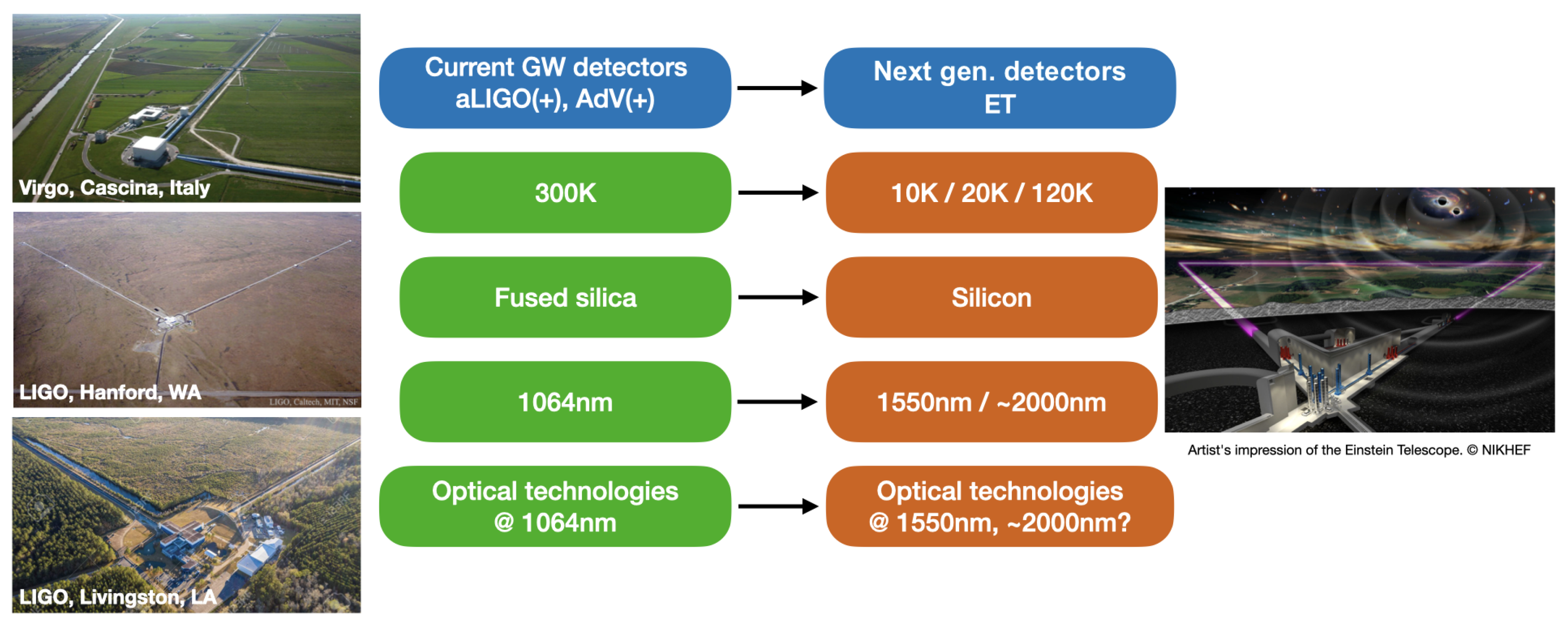
2.1. State of the Art: Lessons Learned from Current GW Detectors

The present subsection summarizes the main technologies concerning test mass payload that can be exploited in ET to build up a feasible project for a cryogenic payload.

2.1.1. Advanced Virgo Suspension System

Several aspects and features of Advanced Virgo are relevant to the activities of ARC regarding the design of ET. Among those (see Figure 3), the seismic attenuation system and the mechanical structure of the payload are of great interest. The seismic attenuation system, called Superattenuator (SA) [52,53,54,55], is used to isolate the test-mass payload (see Figure 3), it was designed in the nineties and it is very close to what is needed for ET-LF.
The mechanical structure of the payload is of importance, being suspended from a single wire. This allows locating the suspension bending points of both steering stages (marionette and mirror) close to their respective center of mass, leading to the optimization of angular modes to the lowest values (∼50 mHz for pitch and roll). Advanced Virgo (AdV) also enables the realization of a composite monolithic suspension, which may be designed in separate components and subsequently assembled. Furthermore, ARC can learn a lot from the challenges of the next upgrade of Virgo (AdV+ Phase II, 2024), as shown in Figure 4, where the mass of end mirrors will be increased from 40 to 105 kg. This is mainly due to the fact that the assembly of a suitable payload with large mass mirrors is not so trivial, in common with ET.

2.1.2. KAGRA’S Cryogenic Suspension System

KAGRA, which belongs to the current generation of ground-based GW detectors [3], represents an important step towards ET-LF as it adopts both underground and cryogenics operations [16], and for this reason, it is often referred as a “2.5G” GW detector. Its installation in Japan finished in 2019 and, after one year of commissioning, in February 2020, KAGRA started its first observing run, terminated in April 2020 [3].
Concerning test masses and the whole isolation and suspension system, KAGRA inherited and further developed a configuration that arose through a worldwide collaborative effort. In fact, the passive attenuation system is inspired by Virgo concept, while the digital control hardware (and software) is the same as in LIGO. Interestingly, the payload merges mechanical and electromechanical aspects of both Virgo and LIGO cases.
Some of the important choices already adopted in KAGRA have been regarded as guidelines for the cryogenic project now being developed at ARC, which will be explored in detail in the following subsections. To name a few, conduction is considered as the primary cooling technique (no use of fluids), and cryogenic ducts are regarded as separating the cryocoolers from the cryostat to prevent transmission of vibration. Additionally, the possibility of Hydroxide Catalysis Bonding (HCB), developed in KAGRA to reduce the thermal noise at interfaces of sapphire elements [3,57], for Al2O3 and also for Silicon (possible alternative materials) should be investigated.
Figure 5 shows a schematic diagram of the KAGRA suspension system and cryogenic payload. Structurally, the design appears inspired by the first generation of room temperature Virgo payloads, but with two new features. The marionette is split in two (lumped) parts: DC motorized steering and actively controlled part (IM) for operation set-point lock.
Given the foregoing context, the primary emphasis of ARC’s activities are payload concept design and cryogenic testing. On one hand, ARC uses computer simulations to arrive at a desirable mechanical design for ET’s payload that exhibits acceptable thermo-mechanical behavior. This is covered in further depth in Section 2.2. Section 2.3, on the other hand, offers some information on ARC’s efforts related to the construction of a facility that will allow cryogenic testing on a full-scale prototype of the model after it has been finished.

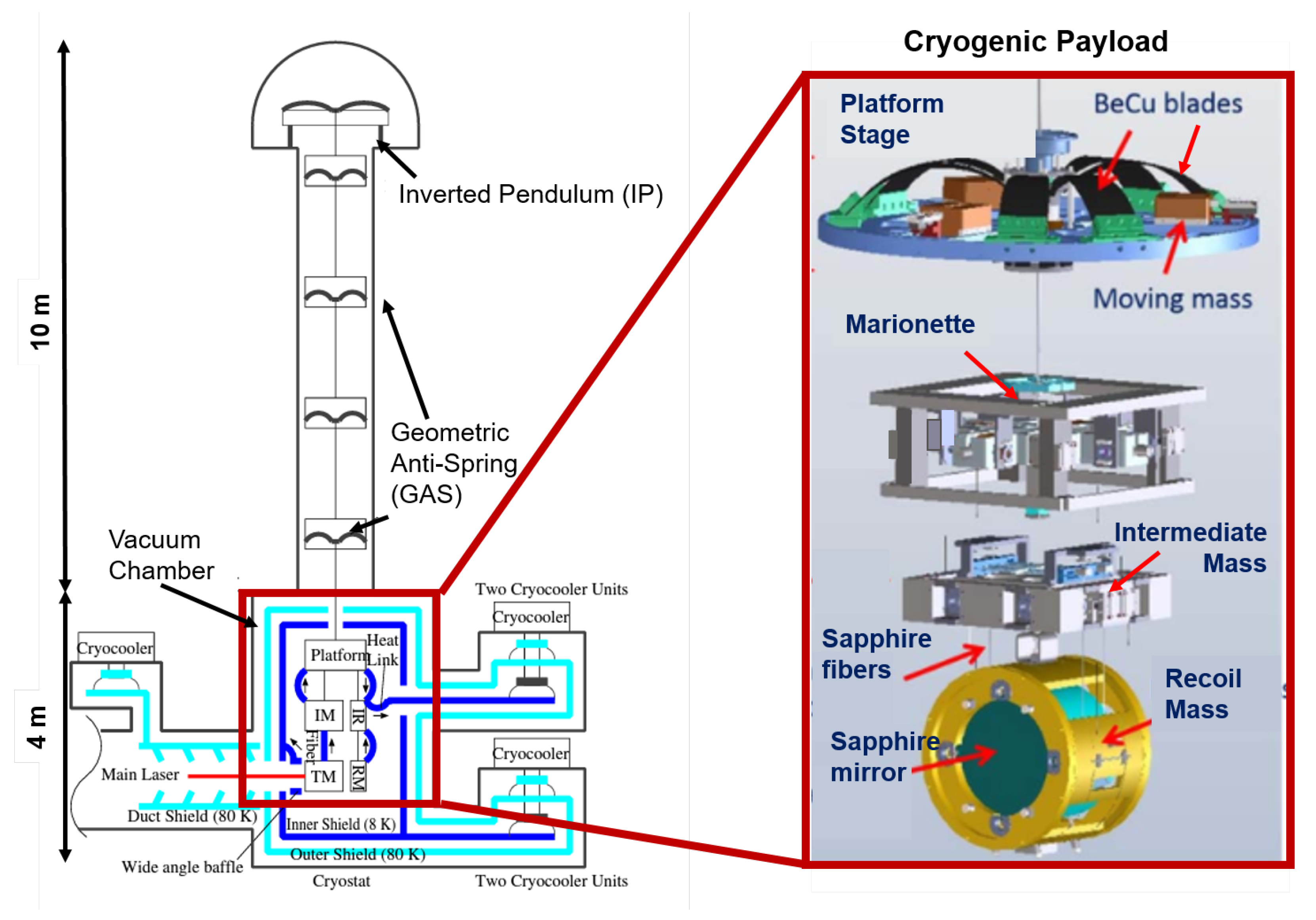
2.2. Payload Development at ARC

While providing early payload design for ET, ARC attempts to cherish the valuable experiences gained by the community over the past few decades: Virgo (AdV) experience with low frequency room-temperature payloads, pioneering cryogenic prototype developed in Rome since 2006 (EU-FP6), and later at the EGO site [60], and the major and unique vein developed by the Japanese GW groups expressed by KAGRA [61]. The main components of the envisaged prototype at ARC include the platform (as in KAGRA), reaction actuation cage (a single body), marionette and a hanging dummy mirror. Splitting the marionette in two bodies will also be considered but not at the first stage of development. The purpose of the project is the following:
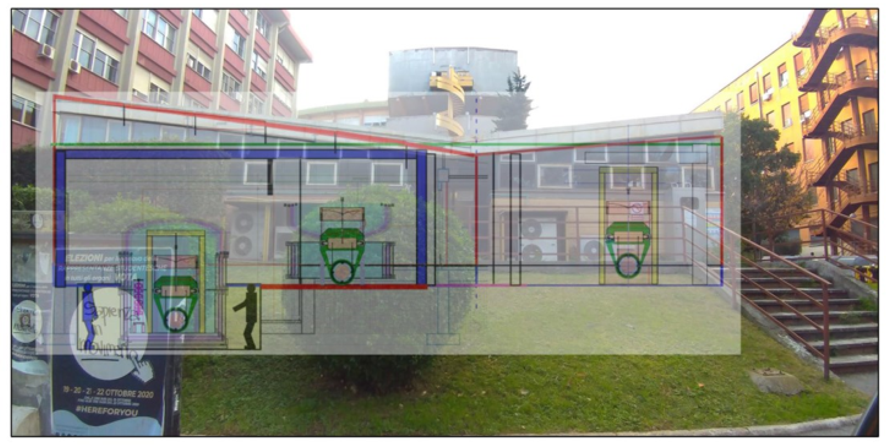
  • Defining a reasonable size for the inner shield of the cryostat (see Section 2.3), mainly the height while also paying attention to the horizontal section.
  • Designing a feasible configuration for the prototype, accounting realistic prediction of thermal noise and seismic noise through the cooling system [62].
The key features are the following. First, the adoption of long fibres for both marionette and mirror (approximately 100 cm), made of materials with high thermal conductivity and high quality factor, such as sapphire or crystalline silicon. The production of properly sized sapphire fibres is already feasible, though further optimization is expected in the next years [63].
To evaluate the production limits of quality sapphire and silicon fibres in terms of length and purity, collaborations with Institut Lumière Matière of the University of Lyon and Norwegian University of Science and Technology (NTNU) are ongoing. In order to pursue this plan, the issue of anchoring crystalline suspension is of principal relevance and will be the topic of the main R&D, leading to the construction and test of double hooked suspension element. The ”quasi-monolithic” solution chosen for KAGRA ensures thermal conductivity, but the monolithic double-head suspension element must still be fully developed in order to achieve the high quality factor demand.
The third crucial element being studied at ARC is the marionette, whose structure, especially in case of sapphire suspension, will adopt high quality factor blades. It is also foreseen to adopt a solution, which permits easy removal of suspension elements (without causing damage) is advantageous due to high manufacturing cost of suspension elements.
The finite element method (FEM) is implemented to analyse and study the corresponding thermo-mechanical response of the early payload design, developed at ARC. This consists of a full-scale prototype with Si 2 O 3 or sapphire mirror (diameter of 550 mm and mass of 130 kg), a marionette of same mass, and sapphire wires of 2.2 mm and 5.4 mm for the mirror and marionette, respectively.
All the suspension elements will be tested at low temperature concerning the breaking strength, mechanical quality factor and thermal conductivity through collaboration with Urbino, Perugia, Tor Vergata at EGO (Virgo site), in close collaboration with KAGRA. ARC is not considering small-scale prototyping to be rescaled at later stages; rather, the entire design process is built around the idea of a full-scale prototype since the beginning. Technology should be gradually developed and, eventually, the payload prototype will be assembled with a dummy mirror with the equivalent mechanical dynamics.
The payload structure will embed all the crucial crystalline components involved in the cooling process. The actuation cage, suspended by means of wires, will be inspired by both Virgo and KAGRA experience. The same body can be used to actuate on both marionette and test-mass. Very low stiffness heat links [64] will be certainly needed to connect the actuation cage to thermal radiation shields, but the concept ARC will pursue is the minimization of their presence in the lumped chain marionette-mirror. At the level of the mirror, KAGRA-like ears, attached using hydroxide catalysis bonding, can be adopted [65].

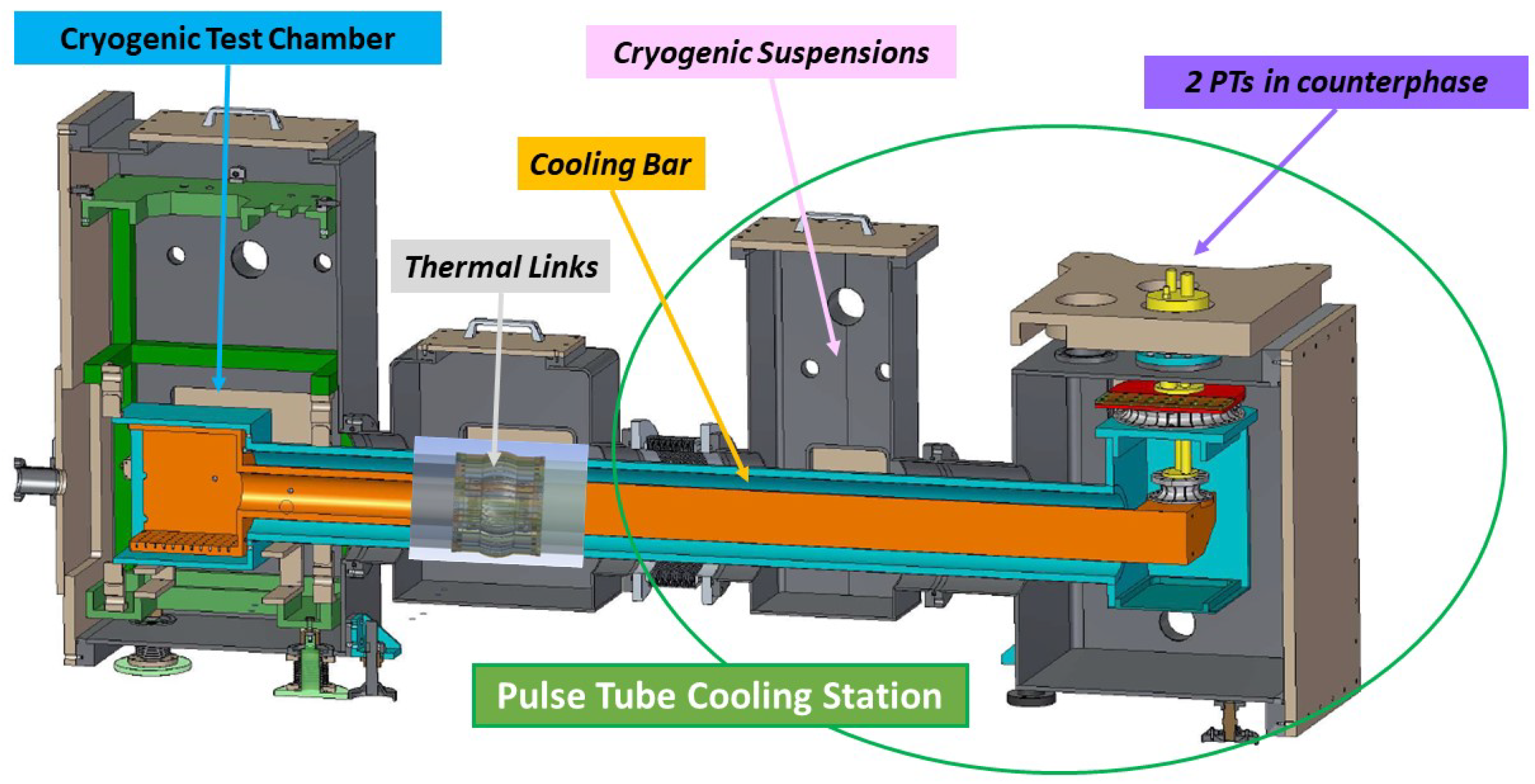
2.3. Cryostat and Cryogenic Cooling System

The laboratory infrastructure at Sapienza University is under construction as shown in Figure 6. Its first purpose is testing a cooling line module (Figure 7), which has been designed and is now under construction, leading to the installation of a full cryogenic facility. The pulse tube cooling station design is the result of local cryogenics experience and collaborative contributions inspired by the pioneering work of KAGRA team [14,58,61,66,67] and CUORE (Cryogenic Underground Observatory for Rare Events) [68].
Two pulse tubes Cryomech PT400 (1.8 W at 4.2 K) have already been bought by Amaldi Research Center. They are meant to operate in counterphase, and connected to a 5 N pure aluminium (Al5N) thermal duct, mechanically suspended and decoupled from the cryostat. Soft heat links (Al6N) are being designed, following the Japanese experience [58,67], to connect the bar to the cold stages and the cryostat inner shields. Initially, the device will be tested using a service small cryogenic chamber equipped with vibration sensors (on the left in Figure 7).
The application for the large cryostat funding has not been finalized at the moment. We envisage a test cryostat of about 3.5 m in diameter and 3.5 m in height (dimensions limited by the host building). It will be designed to be as close as possible to the ET requirements but focused only on the local test of a full-scale payload. Namely, there will not be any super attenuation system installed above the vacuum chamber, and the access will be implemented through a side flange. We also plan to install a prototype pipe, cooled down by another refrigerator, to test the radiation input impinging on the dummy mirror. In ET, we foresee the use of four cooling units similar to the prototype we are building.
The schedule of the activities is the following:
  • Test of the pulse tube cooling station (equipped with two Cryomech PT400) under construction.
  • Payload design followed by one-by-one tests on crucial parts and then by prototype construction.
  • Cryostat design driven by the overall suspension structure and cooling procedure.
  • Test of the payload prototype in clean room at room temperature and study of the characteristic frequencies with their dissipation at high and low frequency.
  • Cryostat construction followed by cryogenic tests.
  • Payload integration and test of the integrated system.
We plan to have a prototype payload by 2024 and, if suitable funding is granted, to start the commitment for the cryostat construction in 2023. The cryogenic facility will be available for cryogenic tests on different type of full-scale payloads for the Einstein Telescope.

3. Etpathfinder

3.1. Introduction

ETpathfinder [71,72] is currently in its initial construction phase in Maastricht in the Netherlands. This project will develop and integrate suspended silicon mirrors with novel suspension elements in a 10 m prototype facility and aims to verify the technical readiness of subsystems, such as laser systems as well as photo-detectors, that are currently under development at new laser wavelengths applicable to ET (1550 and 2090 nm).
As outlined in the introduction of this article, the requirements on a pre-stabilised laser system (PSL) are quite stringent. While the development for a 1550 nm PSL is on a very promising path [73] (this system will be implemented and tested in ETpathfinder), the availability of a suitable ∼2000 nm laser source and PSL is a large challenge. This statement can also be transferred to suitable photo-detectors.
While the availability for 1550 nm high quantum-efficiency (QE) photo-detectors is promising with state-of-the-art InGaAs photo-diodes, there is currently no suitable solution for ∼2000 nm. ETpathfinder will help and push the development of these subsystems and will be able to test them in a full interferometric setting. To give an example, for a laser system at ∼2000 nm, ETpathifnder will use a laser source at 2090 nm and develop a suitable PSL.
The necessity of moving away from the well-known NPRO laser source at 1064 nm (at which all current GW detectors, including KAGRA, operate [1,2,3,4]), stems from the aspiration to operate the interferometer at cryogenic temperatures with silicon optics. The new cryogenic operating temperature requires to abolish the amorphous mirror material fused silica due to high mechanical loss at low temperature and to move to crystalline materials, such as silicon or sapphire. Figure 8 outlines the changes and challenges when moving from the second generation GW detectors to the Einstein Telescope or other third generation GW detectors.
In the ETpathfinder project, the baseline for Phase 1 is to operate two independent interferometers with 15 cm diameter, 8 cm thick float zone (FZ) silicon mirrors to minimize optical absorption in the input test masses of the Fabry–Perot (FP) arm cavities. A detailed description of the ETpathfinder test masses can be found in Section 3.2.2. ETpathfinders uniqueness stems from the fact that it will operate two interferometers at the same time, while utilizing two new laser wavelength, 1550 and 2090 nm; both potential solutions for ET.
At the same time, it will be able to investigate these two interferometers at two cryogenic temperatures, 15 and 120 K; chosen to be near the zero crossings of the thermal expansion coefficient of silicon. Due to its cryogenic nature, ETpathfinder will also be able to investigate new challenges, such as the growth of ice on its main mirrors that has recently been observed in the KAGRA detector [74].
Based on the findings in ETpathfinder mitigation techniques for this new challenge can be developed and tested in the ETpathfinder prototype interferometer. As a unique full cryogenic Fabry–Perot Michelson interferometer utilizing silicon mirrors and new laser wavelengths, ETpathfinder will address all the challenges outlined in Figure 8. This includes investigations of advanced quantum noise reduction technologies, such as frequency dependent squeezing [75], or a speedmeter topology [76].
These techniques can be investigated in a full interferomteric setting, and ETpathfinder will be able to achieve this while operating with novel technologies. The R&D programme to outline a set of verification experiments is currently under development. For this article, we give examples where applicable, and we focus on highlighting a subset of the design choices for the ETpathfinder project as per design report [71].

3.2. Key Technologies

This section highlights three selected key technologies that make ETpathfinder the unique research facility it aspires to be. Starting with the general mechanical and optical layout, the cryogenic system and the silicon mirror-suspensions of ETpathfinder will be described in more detail. Due to the nature of this article, not all ETpathfinder key technologies can be described here. For an in-depth description of the project and its key technologies, further information can be found in the ETpathfinder design report [71] and the ETpathfinder reference paper [72].

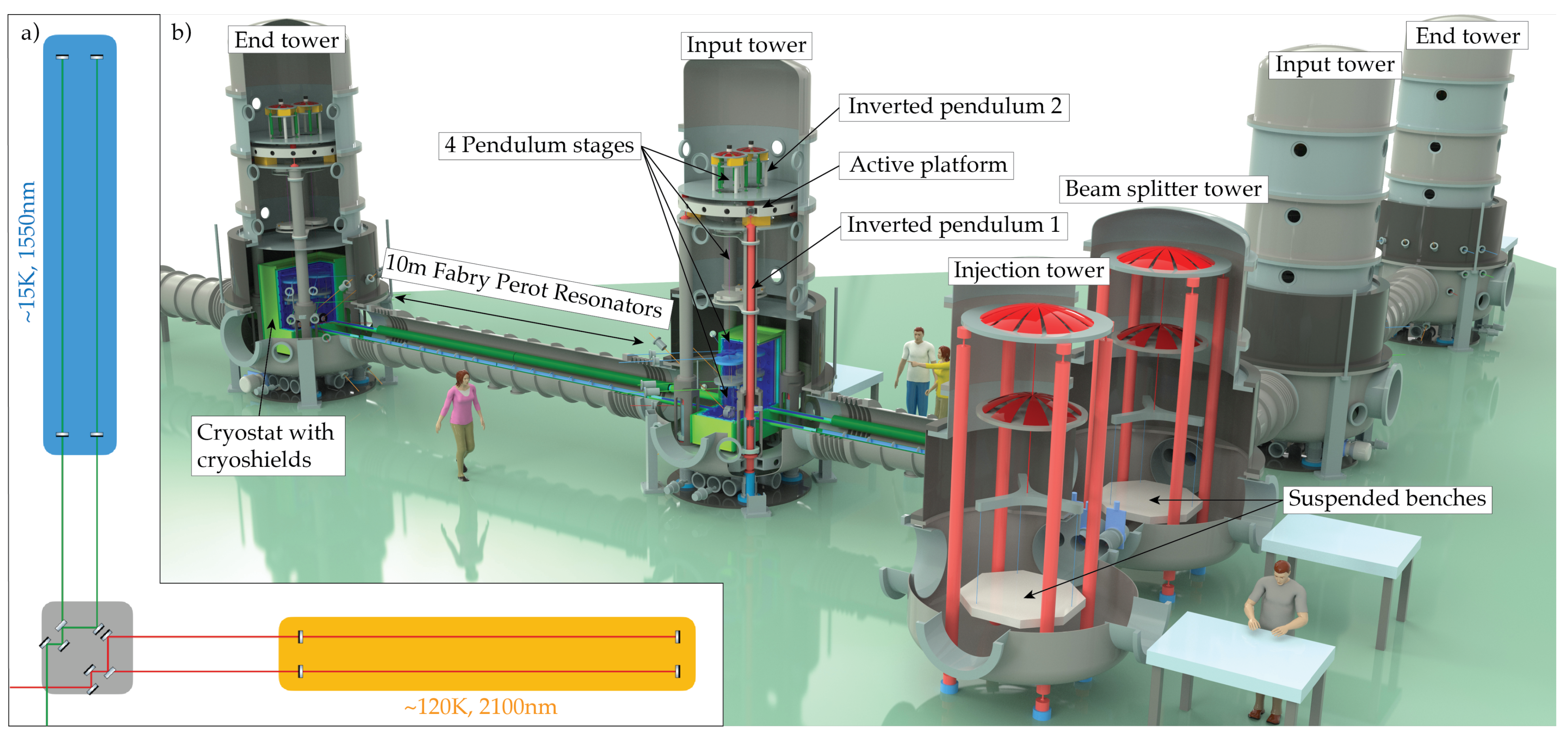
3.2.1. Layout of ETpathfinder

The goal of ETpathfinder in Phase 1 is to verify the technological readiness of the subsystems that are being planned to be implemented in the Einstein Telescope [16]. The parameter matrix that ETpathfinder is going to investigate is of different laser wavelengths (1550 vs. 2090 nm) and different operating temperature (15 vs. 120 K). Despite being hosted in an L-shaped vacuum system, in Phase 1, ETpathfinder will operate with two complete and folded Fabry–Perot Michelson Interferometers (FPMIs); one in each arm. The silicon mirrors used as input end end mirrors of the FPMIs are 15 cm in diameter and with 8 cm thickness. The simplified optical layout for this configuration can be seen in part (a) of Figure 9.
In Phase 2 of the ETpathfinder project, the plan is that the two arms of the L-shaped vacuum system will be equipped with large, ET-like test masses of order 100 kg, with diameter ∼45 cm. It is yet to be determined what type of silicon material will be available at that time and what will be used.
The mechanical layout of ETpathfinder can be seen in part b of Figure 9. The vacuum system consists of six towers in an L-shaped arrangement. Two table towers host optical benches that will be populated with the input and output optics, as well as steering optics and the main beam splitter. The four mirror towers are equipped with a sophisticated seismic isolation system in the form of a dual inverted pendulum system with an active platform in between. From this system a four stage pendulum is suspending the mirror to further reduce coupling from seismic motion. The layout of the lowest suspension stage is described in detail in Section 3.2.2.
In order to operate the interferometer at cryogenic temperatures the input and end mirror of the 10 m Fabry–Perot resonators in the interferometer arms are cooled. To reach the cryogenic temperatures via either radiative cooling to 120 K or conductive cooling to 15 K, the mirrors are housed in a suspended cryostat with a multi-layered cryogenic shield around them. The specifics of this system are summarised in Section 3.2.3.

3.2.2. Silicon Mirror-Suspensions
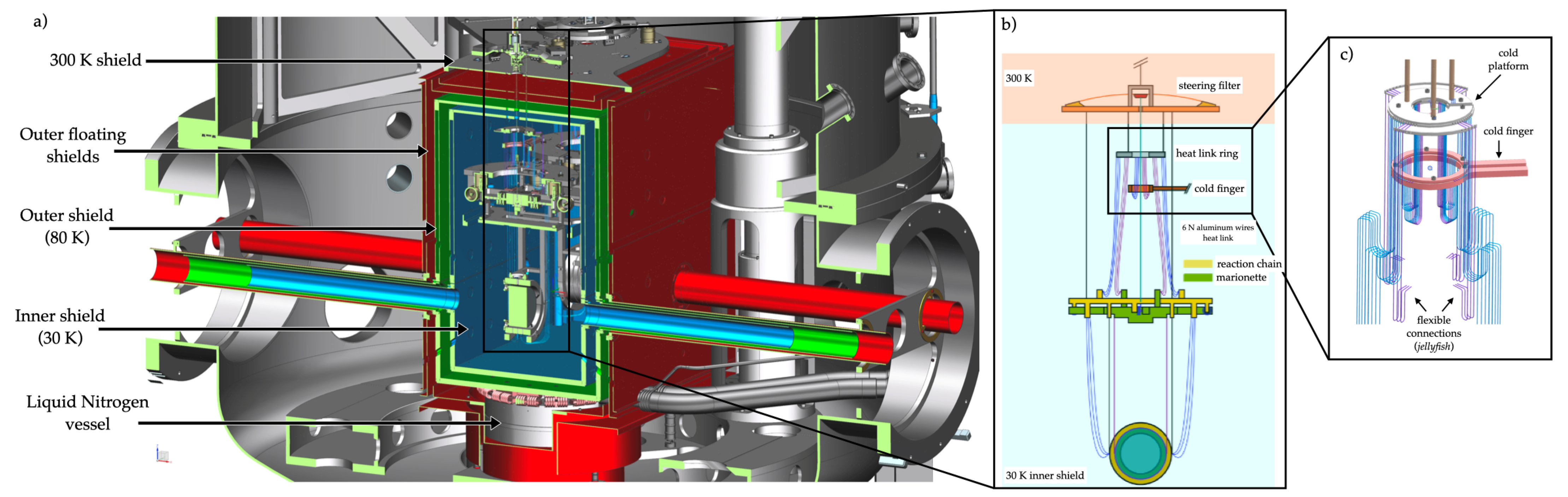
As mentioned in the introduction, utilising a new material for the optics and suspension elements in a GW detector will require extensive research and development. Although silicon has ideal thermal conductivity and low mechanical loss at cryogenic temperatures, it is also a crystalline semi-conductor, which can lead to some additional challenges when understanding its optical and mechanical properties. Thus, the entire process of creating a coated silicon optic that is suitable to be used in a next generation GW detector, such as ET is still to be defined.
The silicon test masses of the Einstein Telescope are planned to be 45 cm in diameter and ∼200 kg in size [16], with a substrate purity that is high enough to allow a 1550 nm or 2 µm laser beam to pass through it without absorbing more than 5 ppm/cm of the laser power. Thus, the first step of finding a silicon mass for ET is finding a source that can grow a large enough diameter and high resistivity monocrystalline silicon ingot. Then, this ingot must be cut, shaped, polished, and optically coated. All these subsequent steps are not currently defined and require further research and development.
In Phase 1 of the ETpathfinder project, it is planned to operate the two interferometers with 15 cm diameter, 8 cm thick FZ silicon test masses. The FZ silicon ingots that were acquired for ETpathfinder have an average diameter of 155 mm and a resistivity of >10 k Ω cm. Within the ETpathfinder project the optical absorption of this material will be measured in a Photothermal Common-Path Interferometer (PCI) [77], to verify its usability. The stringent requirements for polishing the test masses of the ETpathfinder project, follow closely the requirements, such as in advanced LIGO for a fused silica test mass [37] and can be transferred to ET.
Due to its crystalline nature, the polishing of silicon compared to silica is another challenge; however, it should be within the reach of current technologies due to industrial experience regarding X-ray mirrors [16]. In the ETpathfinder project, the aim is to find such suitable polishing companies and work closely together with these companies to receive the highest possible quality of surface polish for the silicon mirrors and to verify their quality in an interferometric measurement in the ETpathfiner interferometer.
In Phase 2 of the ETpathfinder project, starting in 2025, it is planned to operate only one FPMI in the facility, utilising larger silicon mirrors of order 100 kg and with a diameter similar to ET, e.g., 45 cm.
The outcomes from Phase 1 will determine what operating temperature and what laser system will be used in Phase 2. In the design for ET, the plan for the cryogenic silicon suspensions is to have silicon optics attached to silicon suspension elements, hanging on small diameter silicon fibres that, together, would form the quasi-monolithic last stage of the suspension.
Here, the silicon suspension elements fulfil a crucial role, both as a cryogenic heat link between the upper suspension stages and the test mass, and as a low thermal noise connection that is strong enough to hold the ∼200 kg mass. In practice, creating silicon suspension elements presents a considerable mechanical challenge. This is due in part to the crystalline nature of silicon and its high thermal conductivity. Its crystalline nature means that the silicon needs to be grown as one monocrystalline ingot, instead of simply being heated and pulled into a fibre, as is done for fused silica fibres [78].
Grinding down a larger diameter ingot to a smaller diameter fibre and then further processing it in order to attain a well polished surface pushes the limits of what industry can currently provide. Additionally, silicon’s thermal conductivity and tendency to develop high local thermal stress when melted means that connecting the silicon fibres to another suspension element, which is required to connect to the optic, is also challenging. Thus, the CO 2 laser welding used in the fused silica suspensions of AdV and aLIGO is unfeasible in case of silicon.
In the ETpathfinder project, this challenge is increased by the necessity of even thinner silicon suspension fibres that for ET, due to the lighter weight of the mirrors. The development of suspensions and suspension elements for the ETpathfinder project is active research and different methods are under investigation. Currently, mechanically polished suspension rods are being assessed for their quality and usability in the ETpathfinder monolithic suspension. For this, the mechanical loss of these silicon suspension fibres will be measured in a Gentle Nodal Suspension (GeNS) setup [79]. It is further planned to measure the thermal conductivity, and ultimately the breaking strength of these suspension fibres. However, in parallel it will also be investigated if silicon suspension fibres can be grown in a suitable small diameter.
The ETpathfinder project will approach the challenges connected with the use of silicon in different stages. In Phase 1 of the project, state-of-the-art silicon optics will be created, using the highest quality silicon, silicon polish, and optical coatings that are currently available. These optics will first be suspended via metal wires in a newly developed multi-stage cryogenic suspension shown in full in Figure 10a. In Figure 10c, the prototype in its current state can be seen.
In a later stage of Phase 1, the cryogenic suspension will be upgraded with silicon suspension elements and fibres, quasi-monolithicly connecting the silicon optics to the upper mass, as in Figure 10b. As reported above, in Phase 2 ETpathfinder will operate a single interferometer in which large, ET-like test masses will be implemented. This multi-stage approach allows the ETpathfinder collaboration more time to develop methods to create and attach silicon suspension elements, in parallel with developing the process for creating large silicon optics.

3.2.3. Cryogenics

One of the new technologies that ETpathfinder will test is the cryogenic system for the mirrors. The goal is to be able to operate the interferometer at different temperatures: first at room temperature, i.e., 300 K and then at 120 and at 15 K. This means that we need to be able to control the mirror at these temperatures and that the cryogenic system will not limit the sensitivity. We aim to keep the amplitude spectral density of the vibrational motions of the mirrors surfaces below 10 18 m / Hz at 10 Hz. Part (a) of Figure 11 shows the cross section of the tower of the end mirrors.
The mirrors, marionettes and reaction masses are surrounded by three double-walled thermal radiation shields. The inner one (in blue in the picture) is used to keep a temperature of 30 K. The outer shield (in green) is connected to the vessel at the bottom, that contains 40 L of liquid nitrogen and maintains a temperature of 80 K. The floating outer shield (in red) is used to reduce the radiation load on the first shield. In addition, there will be another shield at 300 K (in grey) used to stabilize the temperature of the filter present on the top.
While 120 K can be reached using radiative cooling without introducing significant vibrational noise, going below 100 K requires conductive cooling. This is done using flexible connections of ultra-pure aluminium wires, called “jellyfish” (see part (b) and (c) of Figure 11).
The cold finger (in pink in the figure), which is connected to the inner shield, is the lowest temperature heat link and it ends into two rings, one for each test mass. The rings are connected to the cold platform through the “jellyfish” construction. The “jellyfish” wires connect the cold platform to the marionette (in purple in the figure) and to the reaction chain (in blue), that is hanging from the geometric anti-spring (GAS) filter present on the top of the thermal shields. The presence of two stages helps to reduce the vibrational noise. The mechanical transfer function of the “jellyfish” is measured at Nikhef beforehand on the payload prototype shown in part c) of Figure 10.

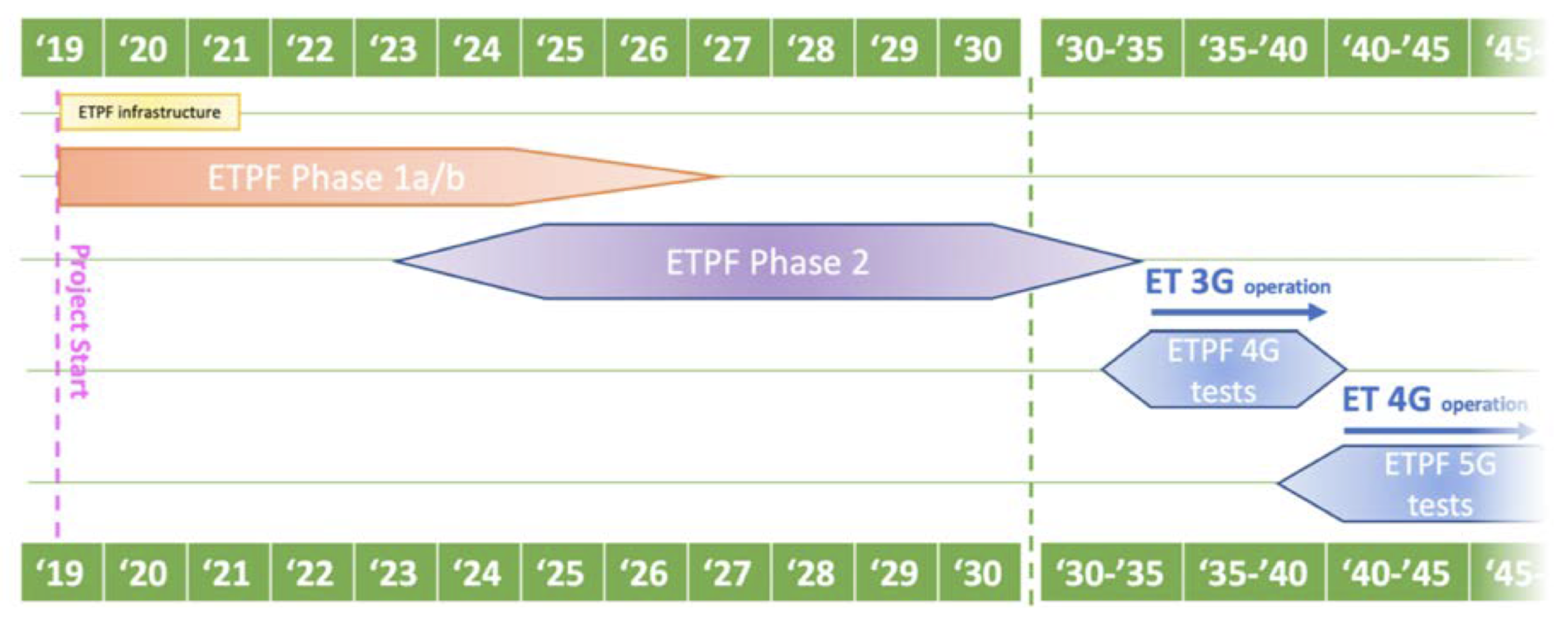
3.3. Status and Future Plans

ETpathfinder is under construction at the University of Maastricht and its timeline is shown in Figure 12. We are currently in Phase 1, at the end of “ETPF infrastructure” phase, with only the vacuum system that still needs to be completed. While the infrastructure works are underway, payload prototypes for preliminary tests are being built.
The prototype of the payload, aka “Proto-0” (shown in part c) of Figure 10), is ready and measurements of the transfer function are in progress. This prototype includes the test mass, the reaction mass and the marionette. Meanwhile “Proto-1”, which includes the inverted pendulum, is being built and it will be ready soon. During Phase 1 two temperatures (15 and 120 K) and two wavelengths (1550 and 2090 nm) will be studied, one in each arm of the L-shaped vacuum system.
Around 2025, ETpathfinder will enter Phase 2. In this phase, it will work on a single temperature and wavelength, which will be chosen depending on the outcome of Phase 1, and with test masses similar to the ones that will be used for ET. Phase 2 is planned to end around 2030, in order to be able to give useful inputs for the ET final design.
Apart from the already mentioned new technologies, new Quantum Noise reduction techniques are also planned to be tested in ETpathfinder. These techniques could further reduce low-frequency noise in next generation detectors.
The life of ETpathfinder, however, will not end with the birth of ET. ETpathfinder has been designed to be as flexible as possible, in order to be used also as a test facility for future upgrades of any third generation GW detector.

4. Sargrav Laboratory

The surroundings of the Sos Enattos mine in Sardinia are considered as a possible location for ET due to its very low seismic and anthropogenic noise. Such local characteristics allowed the construction of the SarGrav laboratory aiming to host underground experiments, such as low seismic noise experiments, cryogenic payloads, low frequency and cryogenic sensor development. Nonetheless, a fundamental physics experiment, Archimedes, is the first experiment in Sos Enattos’ surface area.

4.1. Sos-Enattos Site

The Sos Enattos Mine, located in Sardinia in the territory of Lula, stands on a European tectonic plate far away from any fault lines making its micro-seismic activity among the lowest on Earth, and it has one of the lowest population density in Europe resulting in an area of low anthropogenic disturbances.
Since the site has been nominated to host ET, a strong effort has been conducted to characterise the site in terms of geology, environmental and seismic noise, and a laboratory located at the mine was build, namely SarGrav. Such a laboratory currently hosts sensors and experiments: four broadband triaxial seismometers (one surface vault installation, three underground); three short-period triaxial seismometers; two magnetometers (one buried at the surface and one underground); one tiltmeter (the Archimedes prototype); and one weather station.
Long-term measurements at different depths are ongoing, exploiting the potentialities offered by the Sos Enattos mine. The seismic data from 1 January to 30 April 2020 at two different depths around Sos Enattos were analysed (SOE0 is 400 m above sea level and SOE2 is −110 m with respect to SOE0). In Figure 13 ([80]), the probabilistic power spectra density (PPSD) was obtained using Ref. [81]. A PPSD study implies that transient noise lines (if not stationary disturbances) disappear against the stability of the natural background.
The PSD calculation was done with the obspy tool [82] and a Konno–Omachi smoothing procedure was applied [83]. Between 5 × 10 3 Hz and 2 × 10 1 Hz the PPSD of the underground station SOE2 follows the new low-noise approaches Peterson’s New Low Noise Model ([84], NLNM).
The seismic noise between 0.1–1 Hz is dominated by microseismic peaks from sea waves, which are seasonal features. A peak around f 0.2 Hz is seen in the Figure and it is caused by secondary microseism. In the frequency interval of 1–10Hz (Figure 13c,d) the noise of both stations reach their lowest values respectively at 3.5 Hz (≈ 154 dB) and 4.5 Hz (≈ 157 dB) meeting ET’s criteria of a noise level of −154 dB at 4 Hz even at surface [80]. The PPSD is affected by the self noise of the digitizer, increasing the noise above 3 Hz. New measurements at Sos Enattos with a reduced input range of the digitizer shows that the seismic noise at Sos Enattos (SOE2) between 3 Hz and 7 Hz crosses the NLNM (Ref. [85], Figure 14).
Above 1 Hz, the noise is mainly due to the low population density of the region. Nonetheless, the acoustic noise in the mine has not been affected by any artificial ventilation systems as the mine has a natural airflow (see [86]). Additionally, the main magnetic noise contribution at Sos Enattos is related to the Schumann resonances of the Earth’s magnetic field (see [86]).
The correlation between the seismic PSD amplitude with the wave height provided by Copernicus Marine Environment Monitoring Service (CMEMS) in the western Mediterranean sea and the Biscay Bay (Atlantic Ocean) from April to August 2019 at Sos Enattos was also performed [86].
CMEMS provides reference information on the dynamics of the ocean and marine ecosystems for the global ocean and Europeans seas. Such a study showed that the dominant noise contribution comes from the Tyrrhenian Sea, and the best correlation between microseism and sea waves was found for waves with a period of 4.5 s. The maximized ground vibration, due to sea waves at T = 4.5 s, is on the west part of the island with microseismic peaks at f = 0.22 Hz [86].
The mine per se has a significant infrastructure, and studies as well as an experiment are in motion to scientifically explore the area proposed for ET.

4.2. Archimedes, the First Experiment in the SarGrav Surface Laboratories

Due to the very low seismic and anthropic noise, SarGrav laboratories are suitable to host experiments requiring a very quiet environment. Archimedes is a fundamental physics experiment currently installed in the SarGrav surface facilities, which aims at measuring the interaction between quantum vacuum fluctuations and gravity. Due to its configuration, Archimedes prototype contributed to the direct ground tilt measurement (which is defined as the absolute angular motion of the ground) at the Sos Enattos site in the frequency region between 2 and 20 Hz, which is a region of interest for ET seismic noise characterization. Hence, it has shown to be a suitable sensor that can contribute to the Newtonian noise cancellation.

4.2.1. Aim of the Experiment

The Archimedes experiment comes within the debate around one of the longstanding problems of fundamental physics: the incompatibility between General Relativity and Quantum Theory [87,88,89]. To add a contribution to this topic, Archimedes will measure the force exerted by the gravitational field on a Casimir cavity whose vacuum energy is modulated with a superconductive transition.
More precisely, an YBCO (Yttrium Barium Copper Oxide) crystal is exploited as a stack of Casimir cavities. Indeed, when the crystal temperature is lowered below the superconductive transition point, the crystal layers become reflective, and they form a series of Casimir cavities on top of one another. In this condition, only zero-point electromagnetic modes that satisfy the boundary conditions can survive inside each cavity.
On the other hand, when the crystal temperature is increased, it goes back to the normal state and behaves like a dielectric; therefore, no boundary conditions for the EM field must be satisfied and all the zero-point modes can survive inside the YBCO sample. In the hypothesis that vacuum energy interacts with gravity, a force directed upwards should act on the Casimir cavity due to the missing weight of the expelled EM modes. This situation is analogous to the Archimedes buoyancy of fluid, after which the experiment takes its name.
The expected torque generated with this modulation is of the order of 5 × 10 13 N m/ Hz when integrated over 2 months. The measurement strategy consists of modulating the reflectivity of the Casimir cavity plates by performing a superconducting transition of the two YBCO samples suspended to the balance arms, as shown in Figure 15. In this way, vacuum energy will be periodically expelled from the Casimir cavity, and its weight will be modulated. To measure this effect, a beam-balance will be used as a small force detector.
To allow the superconductive transition, the whole experiment will be cooled in a cryostat, at liquid nitrogen temperature. Moreover, each suspended sample will be surrounded by a shield, which will periodically heat up the sample to bring it from superconductive to normal state. To allow the system thermalization, the modulation will be performed at few tens of mHz. For such a small force to be detected, a very sensitive beam-balance has been suitably designed, and a first prototype has been realized to test its performances.

4.2.2. The Balance Prototype and the Final Setup

A first prototype of the experiment has been built and commissioned in Naples Federico II University laboratories. Few updates have been performed to improve the prototype performances and sensitivity. The main characteristics of the current version are described hereafter.

Mechanics

A schematic of the beam-balance is shown in Figure 16. The balance arm is 50 cm long and is suspended to two solid columns through two thin wire-like suspensions. Since the balance requires a very high torque-to-tilt transfer function, the moment of inertia and the suspension restoring force must be kept as low as possible.
To satisfy the first condition, the arm is hollow and made of aluminium, which keeps its weight low. To accomplish the second requirement, the suspensions section is made as thin as possible, and two flexible joints of Cu-Be 0.5 mm× 0.1 mm are used for this purpose. If the balance centre of mass is kept within 10 µm from the suspension point, its resonance frequency results as around 25 mHz.

Optical Readout

A coarse and a fine optical readout are used to monitor the balance angular position, both anchored to the ground, so that any arm angular motion is referred to it. An optical lever using a SLED (superluminescent diode) is positioned to have the beam impinging perpendicularly on a mirror placed on the lower face of the balance arm (green trace in Figure 16). The beam displacement is sensed by a quadrant photodiode. This optical readout is used as an initial reference position for the arm tilt (coarse positioning).
The finer positioning is provided by a Michelson interferometer, which warrants a high sensitivity. Represented with the red trace in Figure 16, the interferometer beam impinges perpendicularly on the mirrors, to minimize the coupling with undesired degrees of freedom. The interferometer has two unequal arms. However, to avoid common noises coupling in the output channel, an optical delay line located after the beam splitter reflection and made of four right-angle prisms is used to equalize the optical paths. Finally, amplitude noise subtraction is performed by normalizing the output signal by the input power.

Actuation and Control

To keep the prototype arm in its working point (interferometer output on half-fringe), electrostatic actuators are used. Highlighted in blue in Figure 16, they are made of two metallic 2 × 10 cm plates located along each of the arm ends. A digital filter fed with the interferometer output provides the control, suppressing the low frequency motion and leaving the arm free to oscillate at frequencies higher than the unity gain frequency (0.3 Hz).
The final setup of the Archimedes experiment is currently being installed in the SarGrav surface laboratories, in a dedicated hangar. Unlike the prototype, in the final setup, the measurement arm will be 1.4 m long, and an additional reference arm will be employed for ground tilt cancellation, as shown in Figure 15. The whole setup is installed on a solid support (Figure 17), which will be enclosed in the inner of three vacuum chambers, shown in Figure 17.

4.3. Archimedes Prototype as Tiltmeter

Archimedes prototype represents a good inertial reference for ground tilts in the Newtonian Noise frequency region, since the balance arm is free above the control bandwidth, which is above the Unity Gain Frequency (≈300 mHz). When no samples are suspended at the end of its arms, indeed, the beam-balance can be used as a rotational sensor, i.e., a tiltmeter.

First Tilt Measurements at Virgo and Sos-Enattos

Prior to the start of the Virgo observation run O3, the tiltmeter was installed at the Virgo site, and remained there for several months for a joint data taking with the Virgo interferometer. In particular, the tiltmeter was positioned at the North-end building, on the same floor where seismometers and other sensors are located. This period of data taking allowed the ground tilt measurements at the Virgo site, and close attention was paid to the frequency band of 2–20 Hz.
The results are reported in [91]. At a few Hz, a tilt of 8 × 10 11 rad/ Hz was measured. Above 10 Hz, the spectrum presents few resonances, which resulted to be partially coherent with the signals from neighbouring seismometers or interferometer dark fringe signal. Moreover, the tilt noise level detected between 10 and 20 Hz was found to be compatible with the tilt measurements performed at the LIGO sites [92]. Finally, very interesting results where found by comparing the reconstructed tilt signal from seismometer array and the tiltmeter signal [93].
In February 2020, the balance prototype was moved to the SarGrav laboratories in Lula. After few months of updates, devoted to the optical delay line installation and to the amplitude noise subtraction implementation described above, the site tilt was measured in the NN frequency region (2–20Hz). The results are reported in [90].
In Figure 18, the ground tilt measured at Sos-Enattos site (blue curve) is compared to the ground tilt measured at Virgo (red curve). The level of ground tilt measured at Sos-Enattos is around 10 12 rad/ Hz , which is two orders of magnitude below the tilt noise level at the Virgo site. To stay conservative, the value of tilt measured at Sos-Enattos is taken as the tiltmeter sensitivity. This means that the instrument can measure the Virgo site tilt with an SNR greater than 100, which is sufficient to be used for the NN reduction in Virgo. On the other hand, this measurement also shows that the tilt level at the Sos-Enattos site is at least two orders of magnitude lower than the Virgo site.
As a plan for the near future, the tiltmeter will be installed at the Virgo site before the start of the next observation run O4 and beyond, to participate to the NN cancellation campaign. At the same time, a similar tiltmeter will still be kept in Sos-Enattos, in order to continue the tilt noise characterization of the site, possibly also underground.
This will surely be helpful for Archimedes ground noise subtraction. At the same time, a further improvement of the sensitivity will allow a more precise measurement of the ground tilt level in Sos-Enattos, which can add important knowledge about the tilt noise level at the Sardinian site, providing a reliable projection of this kind of noise source on the ET sensitivity curve.

5. Einstein Telescope EMR Site and Technology (E-TEST)

The main activities and technologies used in the E-TEST are addressed in this section. It first presents the objectives of the E-TEST and its main tasks. Then, an overview on the cryogenic and suspension design are demonstrated. Lastly, a detailed description of the site characterization is presented. Further details are shown in the following subsections below.

5.1. Introduction and Objectives

Two directions of research relevant to ET are conducted within E-TEST. A prototype mirror suspension system at cryogenic temperature is being developed and the geological characteristics of Euregio Meuse-Rhine (EMR) region are mapped and investigated.
E-TEST results will shape the ET mirror suspension, auxiliary optics and cryogenic design as well as a thorough study of the EMR region. the main tasks of the E-TEST geological research campaign are:
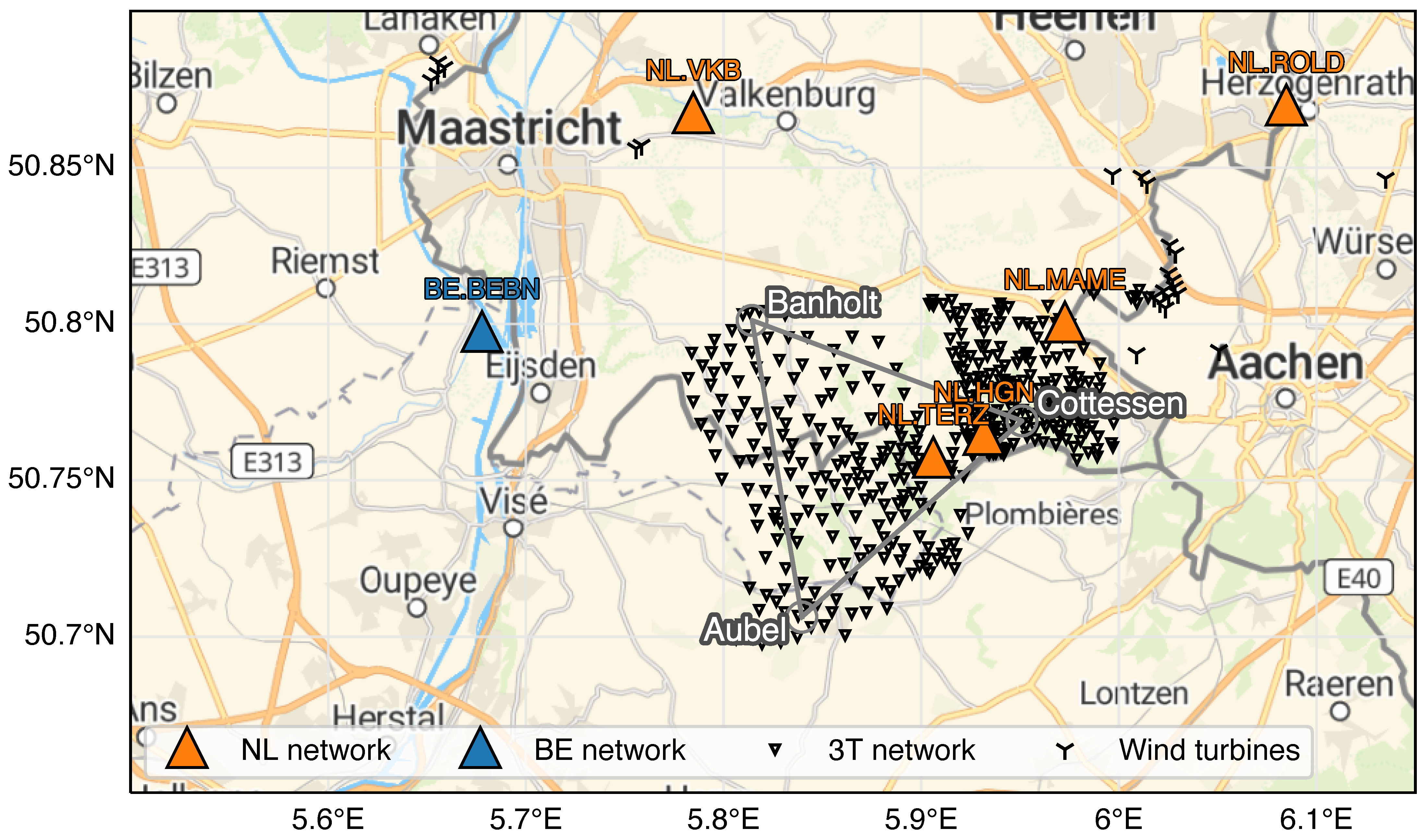
  • characterisation of the ambient seismic field in the region to optimally select the location of the corner points and to guide the seismic isolation system design; and
  • characterisation of the subsurface geology in terms of material properties to guide the geotechnical engineering efforts of such underground infrastructure.
To build a cryogenic suspension prototype for the silicon mirror suspension, a novel approach is adopted mainly to reduce the overall height and the infrastructure complexity. The currently proposed ET suspension system is a 17-m long Virgo-style superattenuator [54]. The E-TEST approach combines a LIGO-style active tables and a Virgo-style inverted pendulum (IP) stage. This will provide better isolation performance particularly at low frequency since the active control stage provides attenuation below its resonance frequencies. The mirror and the penultimate stage will be in a cryostat at T 20 K. The main features of the E-TEST prototype design are the design and the development of:
  • ultra-cold vibration control, which includes vacuum and cryogenics, active vibration isolation and the design of a seismic isolation system; and
  • optical engineering, which includes silicon mirror manufacture and test, laser and optics at 2 microns wavelength and assembly and validation of the whole setup.
The E-TEST prototype will not provide the desired isolation performance of ET since the overall height of the prototype is limited by the vacuum chamber height (4.2 m). However, it will validate the above strategies that make significant improvements to the current design possible.

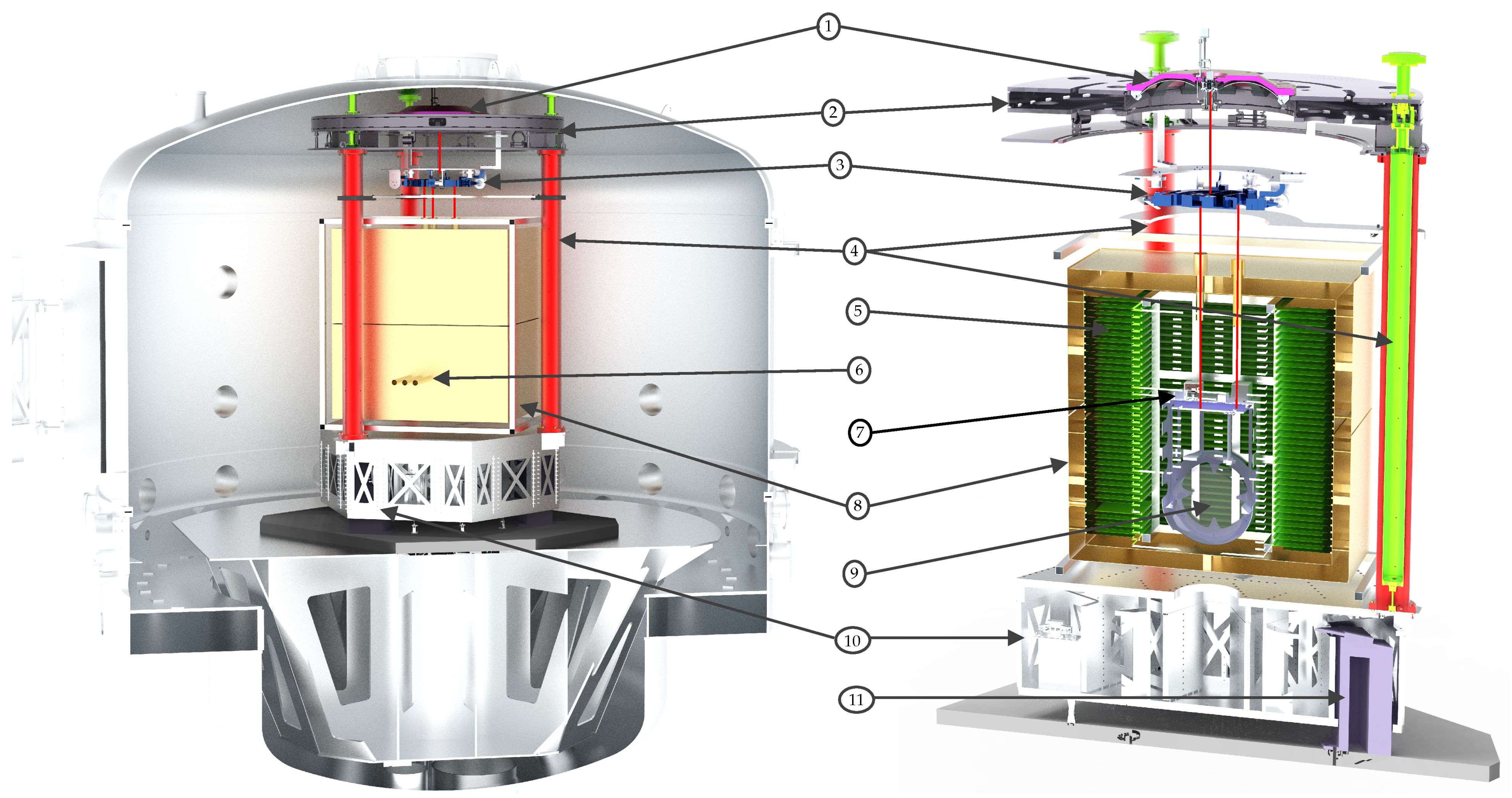
5.2. Design of the Cryogenic Suspension Prototype

As part of E-TEST, a novel approach combining an actively controlled inertial platform, such as LIGO suspension system [12] and an IP stage, such as used in Virgo [94] or KAGRA [95] is investigated. The aim is to decrease the overall height and infrastructure complexity of the initially proposed 17-m-long suspension system of ET [16], which was first presented as a fiducial design in the 2011 conceptual design report [28].
Better isolation performance at low frequency is expected since the inertial control approach yields isolation below the system’s resonant modes, which is not possible with passive isolation systems [96]. The suspension system will be mounted inside a large vacuum chamber in order to eliminate acoustic noise.
The E-TEST suspension system, shown in Figure 19, consists of one active platform that provides inertial control in the six degrees of freedom. The three legs of the IPs are mounted on the active platform and support the top stage. The IP provides a large amount of isolation in the horizontal direction as the resonance frequency can be tuned to extremely low values (about 70 mHz in KAGRA [96] and 30 mHz in Virgo [94]). Additionally, the IP stage provides means for positioning the parts suspended from the top stage, which can compensate for the tidal drift [28,97]. The top stage houses a large Geometric Anti-Spring (GAS) filter for vertical isolation. From the GAS filter, a marionette is suspended, which is mainly used to position the cryogenic payload.
This cryogenic part contains the cold platform and the test mass, which will be operated at cryogenic temperature (20 K). The cold platform is a cryogenic test-bed for sensors, such as the cryogenic superconducting inertial sensors [98,99] and the test mass is suspended. Additionally, a smaller cryostat has been developed with a cylindrical cold volume—down to 6 K-of 15 cm diameter and 15 cm height to test the performance of the cryogenic sensors and equipment before mounting them inside the E-TEST cryostat to validate their operation.
The radiative cooling is provided by a cryostat of which half is part of the suspended penultimate mass, i.e., attached to the cold platform. GW detector designs that use higher mirror temperatures can employ radiative cooling more easily. This is because the total radiated power P rad of an object with emissivity ϵ is directly proportional to the fourth power of the object temperature T as P rad = ϵ σ A T 4 , where σ is the Stefan–Boltzmann constant and A the radiating area. Additionally, ϵ typically reduces significantly for even the most emissive materials and coating at T < 50 K. The only way to radiatively cool mirrors at ET temperatures, i.e., T < 20 K is to increase the radiating area. The E-TEST design achieves this by interlacing a large suspended array of fins with another actively cooled array. The fin structure increases the surface area by more than a factor of 10.

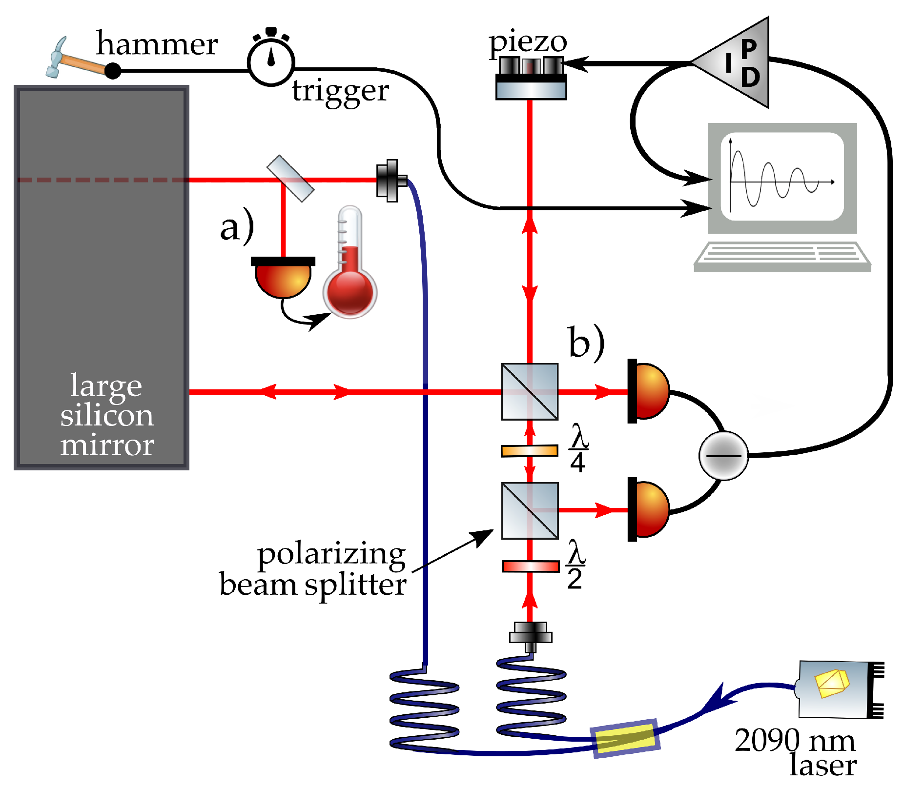
5.2.1. Optical Engineering

Hanging from the suspensions in a cryogenic environment is the large silicon mirror. The goal is to acquire a >100 kg silicon test mass, with an as large as possible diameter to approach the envisioned 45 cm for ET. As mentioned before, a switch to silicon is necessary for cryogenic GW detectors as fused silica becomes mechanically lossy at low temperature.
An additional switch to a longer wavelength laser, e.g., 1550 nm or around 2 micron, is necessary as silicon is only transmissive there. Using longer wavelengths will decrease the shot noise at the same laser power as the lower energy per photon means the number of photons per second, and thus the quantum statistics improve. The silicon test mass will be polished, coated and characterised by various experiments.
Once the test mass is suspended and in the cryostat, the three tubes visible in Figure 19 provide access to the cold mirror. Outside the vacuum tank, a 5–10 W single mode laser with around 2090 nm wavelength is developed. High quality photodetectors at that wavelength are also developed. Lastly, low-loss optical coatings operating at these wavelengths, and conditions unfamiliar to GW scientists and engineers, are under investigation.
The goals for the laser include single mode beam quality and a high stability in output power and frequency combined with a narrow linewidth. To achieve that, a seed-source and a two-stage amplifier system with additional internal stabilization mechanisms will be developed. This approach follows basic laser design based on a Ho:YAG crystal-based seed source to define the spectral properties as well as holmium-doped fibre amplifiers for the power scaling. The photodiode development is strongly coupled to the laser developments to end up with an optimal wavelength match. The photodetectors are characterised in terms of spectral dependence of quantum efficiency, (dark) noise and overall stability. Additionally, optimization of readout protocols is targeted in terms of signal-to-noise ratio and readout speed.
The E-TEST prototype aspires to acquire a substrate with a mass, purity and dimensions well on track towards the ET mirrors (45 cm diameter, 210 kg). After polishing, characterisation of the substrate will take place using three experiments of which two are shown in Figure 20: a white light interferometer for precise mirror surface quality characterisation, an interferometric measurement scheme using the silicon substrate as a Fabry–Perot etalon to determine its temperature [100] and mechanical loss measurements of internal mechanical modes using a fm/ Hz interferometer [101] excited by a tiny hammer, i.e., a small mass-spring element.
Finally, crystalline coating layers are characterised regarding, e.g., their optical and elastic properties, which are important to estimate the noise behaviour of the ultimate coatings.

5.3. Site Characterization

The ET corner points should be as vibration free as possible. In order to identify candidate sites and optimally select the corner point locations, a series of passive seismic campaigns are planned to capture the ambient seismic field. Two data from two campaigns were previously collected and are openly available online through KNMI/ORFEUS [102]. Figure 21 presents the EMR region and the locations of the concluded seismic campaigns.
Additional campaigns are planned, and the data collected will be added to the 3T network (see Figure 21) data archive. The data collected by these campaigns will be used to model the spatial distribution of the noise in several frequency bands. In addition to the broadband response in the 0.5 to 20Hz band, we will study the response at narrow-band intervals. Additionally, the data will be used to image the subsurface.

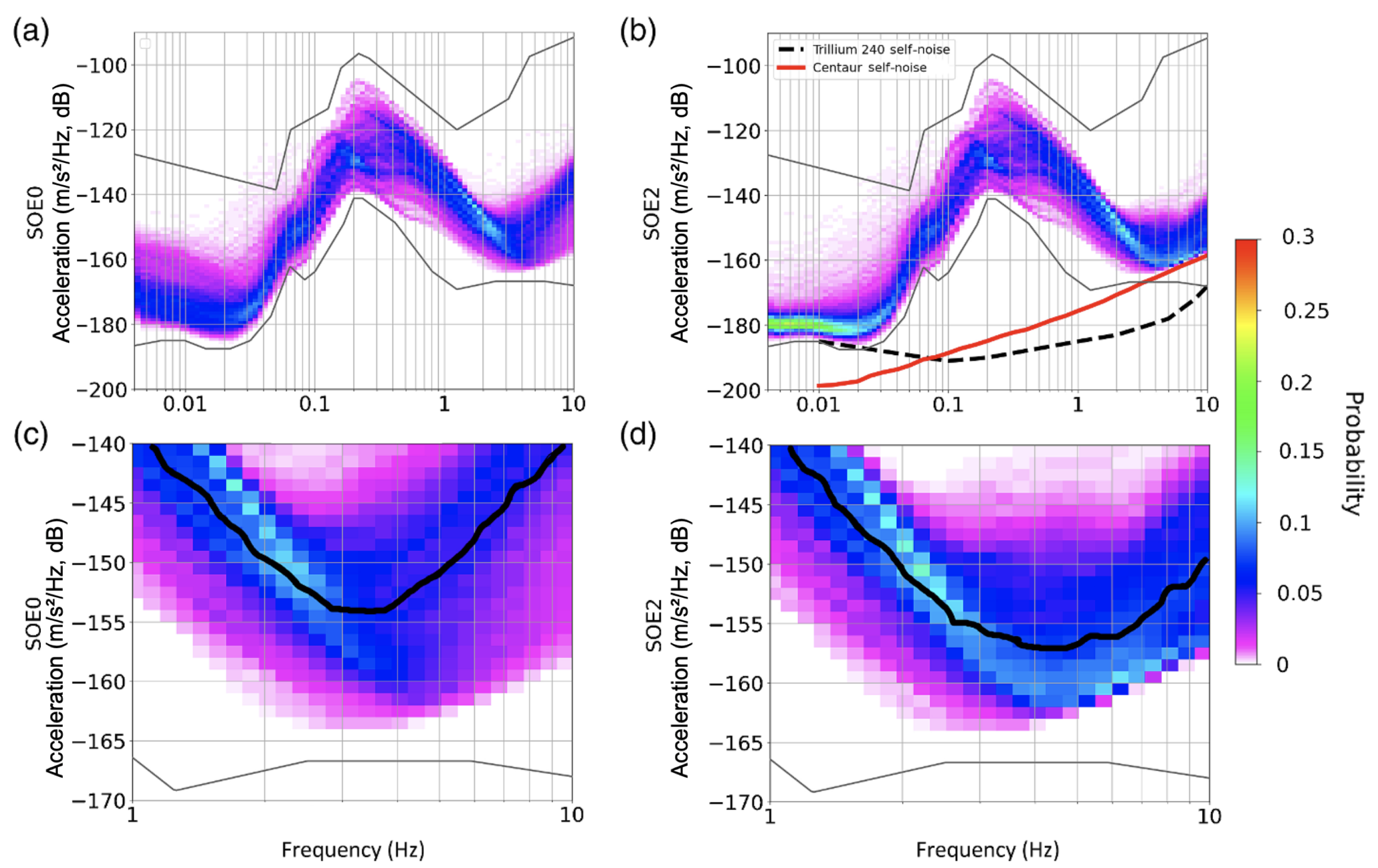
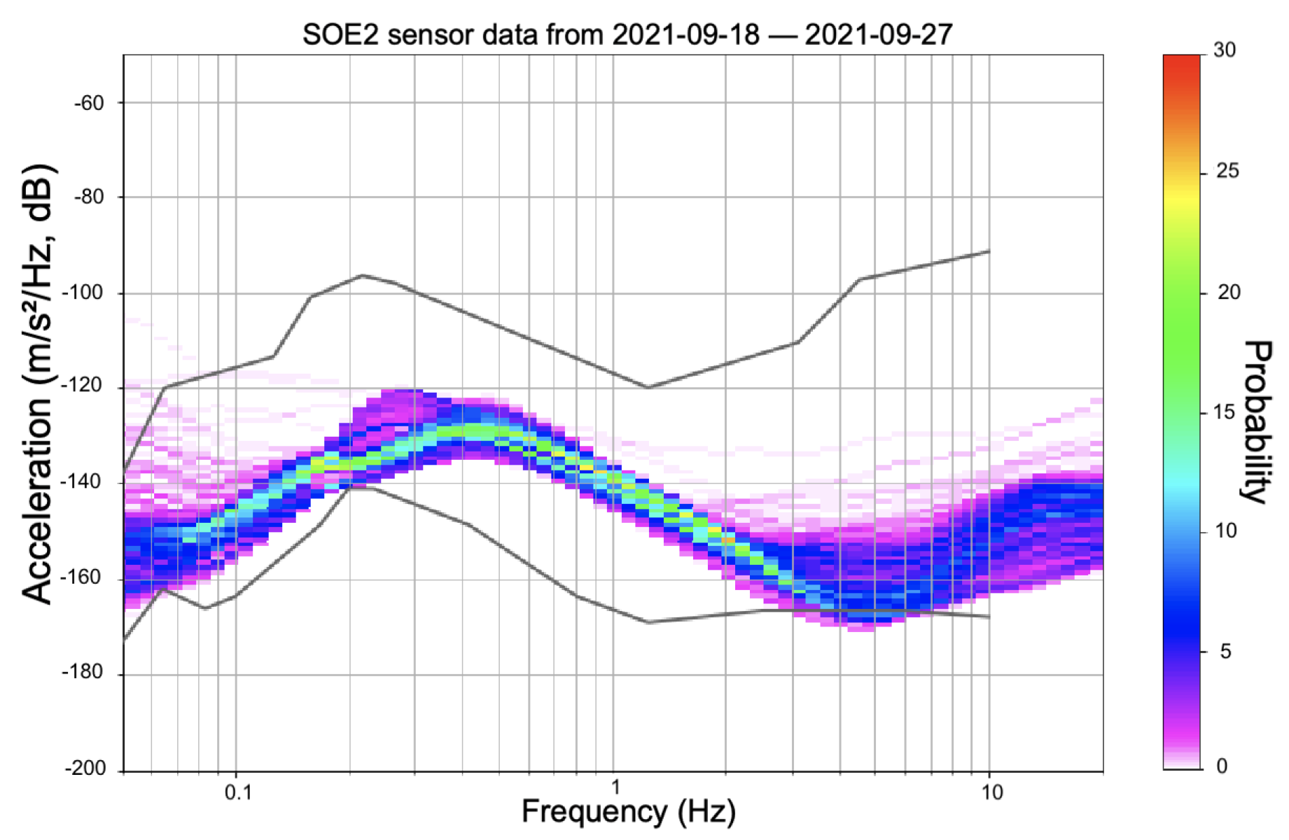
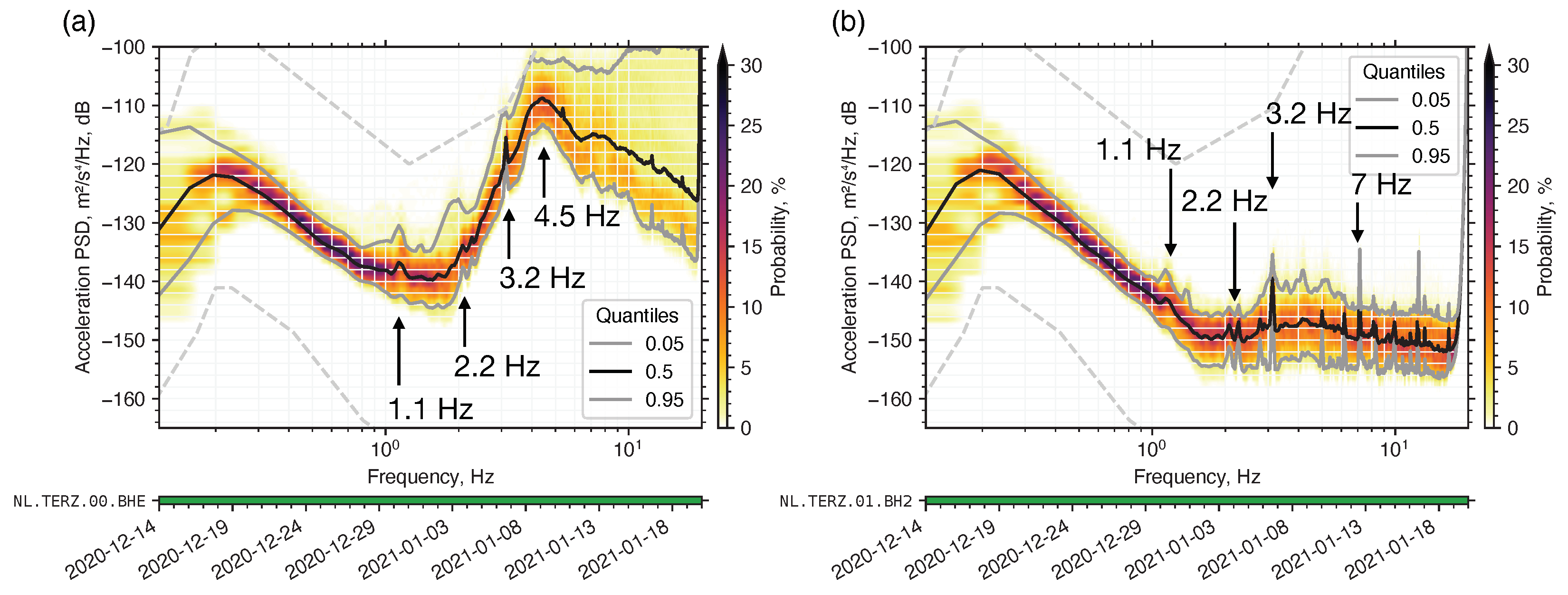
5.3.1. Noise at the Surface vs. Noise at Depth

The first borehole station in the region is the NL.TERZ in Terziet, as shown in Figure 21. The station hosts a broadband seismometer at the surface and at a depth of 250 m. Seismic noise at the surface is generally attenuated with increasing depth, especially when soft, unconsolidated soil layers at the surface overlay hard rock layers. This attenuation is visible in the power spectral density (PSD) calculated for the surface and borehole seismometers. At frequencies above 1 Hz, noise from anthropogenic activity becomes significant. The noise is attenuated by 10 to 40 dB relative to the surface (see Figure 22). However, several spectral peaks are visible both at the surface and at depth.

5.3.2. Spectral Peaks Associated with the Wind Turbines

To trace the origin of the spectral peaks identified in Figure 22a, a seismic monitoring campaign was deployed to the west of the Aachen windpark. The sensors were deployed on 14 December 2020 and retrieved on 19 January 2021. This period was chosen to capture the ambient seismic field during the relatively quiet holiday period (Christmas and New Year’s) and the typically strong winds in the region.
During this period, there were days with almost no wind, and there were days with more than 25 m/s (90 km/h) wind. During this campaign there was also an active swarm of earthquakes unravelling in the vicinity of Rott, Germany, roughly 20 km south-east to the deployed sensors. These were well recorded by the seismic campaign as-well-as by the NL and BE seismic networks.
Figure 23a presents PSDs from select stations at varying distances from the Aachen wind park. The amplitude at the 1.1, 2.2 and 3.2 Hz spectral peaks, which are observed at all stations in the region, are consistently decreasing as a function of distance from the Aachen wind park. Additionally, the amplitude of the entire spectrum, but specifically of the above spectral peaks, is in correlation with wind speed as presented in Figure 23 for the borehole seismometer at 250 m depth in Terziet. The 7 Hz peak is caused by the fundamental vertical resonance frequency in the steel casing lining the inside of the borehole.

5.3.3. Geological Characterisation

The site investigated within the E-TEST project is located in the Euregio Meuse-Rhine region between Belgium (including Flanders and Wallonia), The Netherlands and Germany. Within this region, existent sources of noises have been identified and potential locations of the ET infrastructures minimizing the impact of these noises are defined. In this region, Paleozoic rocks of Devonian to Namurian–Wesphalian ages are found. In the North, these rocks are overlain by Cretaceous and Quaternary soft sediments.
These rocks were faulted and folded by different episodes of tectonic activity. A detailed study of the subsurface is required to consider the feasibility of installing an Einstein Telescope infrastructure a few hundreds of meters at depth given the large uncertainty on geological conditions and the lack of data in the underground. In the E-TEST project, deep investigations are therefore deployed to characterise the EMR underground in terms of geological structures, rocks properties and hydraulic properties.
Different geophysical methods, including active seismic (with sledge hammer and vibro-trucks) or passive seismic surveys, classical or deep (up to 300 m) electrical resistivity tomographies (ERT) surveys, are conducted to collect data from various depth ranges and different resolutions in order to image the shallow and deep subsurface. Deep boreholes (up to 300 m) are drilled along the potential axes of the tunnels and corners of the ET infrastructures.
The cores sampled during drillings are used to perform geomechanical tests to determine the mechanical properties of the rocks. Geophysical and hydraulic testing of these boreholes will be performed after their completion. Seismometers will be installed in these boreholes to study the ambient seismic field at the depth of the ET infrastructures.
All the collected data are used to build a 3D geological model of the EMR region and to select the most appropriate area for the ET infrastructures. The specific implementation of ET for this site will be proposed based on the results of the geomechanical tests. A 3D groundwater flow model of the region is also developed to anticipate and organize potentially needed drainage and pumping during the building and operation of the ET infrastructures. The model will also be used to identify the potential impact of the underground infrastructures on its surroundings.

6. Summary

The research described above works towards the low-frequency goals of ET. The current GW detectors do not reach their design sensitivity below 30 Hz. This is largely due to technical noise, such as couplings between different interferometer control degrees of freedom, some of which are not fully understood [1]. While beyond the scope of this article, we can report on an effort towards improved system design with the control systems in mind, something that was largely lacking in the design of current detector systems. This will enable the fruition of the efforts of the four facilities described here to reach the low-frequency fundamental noise projection shown earlier in Figure 2. In the following, we summarize the research efforts of each research facility.
The experience with a large mass payload for Advanced Virgo will be fundamental for designing a prototype payload for ET. Moreover, given the long-term experience of the ARC team on test-mass payload topics and the close collaboration with KAGRA teams, the promised development foreseen in ET context is sustainable. The construction of the building that will host the next generation GW laboratory in Rome has finally started. The facility is designed to allow the development of a full-scale cryogenic payload prototype. Its design started in 2021 in parallel with the construction of a low-vibration cooling line prototype.
ETpathfinder is a state-of-the-art research facility located at the University of Maastricht. This facility will operate two 10-meter-long interferometers operating at cryogenic temperatures, allowing the team to develop and test technologies for next generation GW detectors within a fully integrated system. Key technologies that are in development at ETpathfinder are the following. The fabrication of mirrors and suspension elements from silicon, a material new to our field. These suspended silicon optics will be cooled to different cryogenic temperatures, e.g., 15 and 12 0K, using new cryogenic approaches at two different laser wavelengths: 1550 and 2090 nm.
SarGrav facility is a laboratory located in Sardinia, Italy, intended to explore the potential of the region in terms of seismic noise to host ET. The laboratory has several extremely low noise infrastructures, designed to host low-frequency seismic noise experiments and cryogenic payloads. Throughout the old mine ducts and elsewhere, there are several underground stations available for site monitoring. This has a strong synergy with ET candidature activities, namely site monitoring, support in terms of logistics and person power, mechanics and masonry services.
Archimedes was the first fundamental physics experiment installed in SarGrav surface laboratories, aiming at investigating the interaction between quantum vacuum fluctuations and gravity. The Archimedes prototype is currently working as a tiltmeter, and has measured a rotational displacement two orders of magnitude lower than the Virgo site in the Newtonian noise band, showing the suitability of the Sos Enattos site.
The 17-m-tall suspension in the current ET designs are largely regarded as placeholders for solutions that are under development. One such development is the E-TEST suspension prototype, which combines active and passive isolation strategies to suspend a >100 kg silicon mirror as well as a radiatively cooled cryostat. The facility is being built at the Centre Spatial de Liège in Belgium. In parallel, the region in the South of the Netherlands, East of Belgium, and West of Germany is subject to geological and hydrogeological investigations to determine the suitability of the said region to host ET.
The research into developing and testing the key technologies described throughout this article will inform the design of next generation GW detectors, such as ET and its many upgrades to come.

Author Contributions

The authors wish to thank their respective collaborations for being allowed to represent the research facilities on this early career researcher writing team. L.P. presented the low-frequency science case as part of the introduction. The ARC team consists of S.D.P., V.M. and A.R. and the ETpathfinder section was written by M.H., J.-S.H. and D.P. SarGrav was described by A.A. (Archimedes) and I.T.e.M. (site characterisation) and E-TEST by V.G.N. and A.S. (cryo-suspension) and P.O. and S.S.-K. (site characterisation). Finally, J.v.H. conceptualised the structure and focused on general logistics, the abstract, introduction, Section 5.2.1 and closing sections. All authors have read and agreed to the published version of the manuscript.

Funding

Amaldi Research Center is an excellence centre in the Sapienza University (Department of Physics) in Rome and it is funded for five years period (2018–2022) by MIUR with an associated CUP number B81I18001170001. The ETpathfinder project in Maastricht is funded by Interreg Vlaanderen-Nederland, the province of Dutch Limburg, the province of Antwerp, the Flamish Government, the province of North Brabant, the Smart Hub Flemish Brabant, the Dutch Ministry of Economic Affairs, the Dutch Ministry of Education, Culture and Science, and by own funding of the involved partners. The SarGrav laboratory is supported by: INFN with Protocollo di Intesa tra Ministero dell’Universita’ e della Ricerca, la Regione Autonoma della Sardegna, l’Istituto Nazionale di Fisica Nucleare e l’Università degli Studi di Sassari; University of Sassari with Accordo di Programma tra la Regione Autonoma della Sardegna, l’Università degli Studi di Sassari, l’Istituto Nazionale di Fisica Nucleare, l’Istituto Nazionale di Geofisica e Vulcanologia, l’Università degli Studi di Cagliari e l’IGEA S.p.a (progetto SAR-GRAV, funds FSC 2014–2020 Patto per lo sviluppo della Regione Sardegna); Università degli Studi di Sassari with “Fondo di Ateneo per la ricerca 2019”; Istituto Nazionale di Fisica Nucleare and by the Italian Ministero dell’ Università e della Ricerca with PRIN 2017 Research Program Framework, n. 2017SYRTCN. L. Loddo and IGEA miners supported the operation in Sos Enattos. Interreg is the European Union’s tool to support cross-border projects, which otherwise would not be conducted. The Interreg V-A Euregio Meuse-Rhine (EMR) programme invests almost EUR 100 million in the development of our region until the end of 2020. The E-TEST project is perfored within the framework of the Interreg V-A Euregio Meuse-Rhine Programme, with 50% funding from the European Regional Development Fund (ERDF). By investing EU funds in Interreg projects, the European Union is investing directly in economic development, innovation, territorial development, social inclusion and education in the Euregio Meuse-Rhine. The E-TEST project is co-funded by the Walloon Region, the Flanders Region, the Province of Flemish Brabant, the Province of Belgian Limburg, the Dutch Ministry of Economic Affairs, the Province of Dutch Limburg, the North Rhine-Westphalia, and by own funding of the involved partners.

Institutional Review Board Statement

Not applicable.

Data Availability Statement

All seismic data for the SarGrav site and the Python code used to produce the plots are available at the site repository https://etrepo.df.unipi.it:8000/(accessed on 12 January 2022). Accounts can be requested by contacting the authors. All seismic data for the EMR site is freely and openly available through https://www.fdsn.org/networks/detail/3T_2020/ (accessed on 8 January 2022) for the 3T network and https://www.fdsn.org/networks/detail/NL/ (accessed on 8 January 2022) for the NL network.

Acknowledgments

For a thorough review, the authors would like to thank Edwige Tournefier and Mario Martinez on behalf of the ET steering committee, and Jeff Kissel on behalf of the LIGO Scientific Collaboration. We additionally express out gratitude for the research performed by all partner institutes. For ARC, these are KAGRA team and CUORE collaboration. For ETpathfinder these are Nikhef, Maastricht University, University of Antwerp, Ghent University, Katholieke Universiteit Leuven, Université catholique de Louvain, Hasselt University, Vrije Universiteit Brussel, Fraunhofer Institute for Laser Technology ILT, RWTH Aachen, University of Twente, Eindhoven University of Technology, Université de Liège, VITO, TNO, LAPP, Albert Einstein Institute, Universitat de Barcelona, Vrije Universiteit Amsterdam and University of Birmingham. For SarGrav these are Regione Sardegna, University of Sassari, INFN, University of Napoli, University of Rome “La Sapienza”, University of Sassari, Ego-Virgo, CNR-INO, Université Aix Marseille. And for E-TEST these are ULiège, Fraunhofer Institute for Laser Technology ILT, RWTH Aachen, UHasselt, KULeuven, Nikhef, UBonn, the NMWP, KNMI, UMaastricht and UCLouvain.

Conflicts of Interest

The authors declare no conflict of interest.

References

  1. Buikema, A.; Cahillane, C.; Mansell, G.L.; Blair, C.D.; Abbott, R.; Adams, C.; Adhikari, R.X.; Ananyeva, A.; Appert, S.; Arai, K.; et al. Sensitivity and performance of the Advanced LIGO detectors in the third observing run. Phys. Rev. D 2020, 102, 062003. [Google Scholar] [CrossRef]
  2. Acernese, F. et al. [Virgo Collaboration]. Increasing the Astrophysical Reach of the Advanced Virgo Detector via the Application of Squeezed Vacuum States of Light. Phys. Rev. Lett. 2019, 123, 231108. [Google Scholar] [CrossRef] [PubMed] [Green Version]
  3. Akutsu, T. et al. [KAGRA Collaboration]. Overview of KAGRA: Detector Design and Construction History. Prog. Theor. Exp. Phys. 2020, 2021, 05A101. [Google Scholar] [CrossRef]
  4. Lough, J.; Schreiber, E.; Bergamin, F.; Grote, H.; Mehmet, M.; Vahlbruch, H.; Affeldt, C.; Brinkmann, M.; Bisht, A.; Kringel, V.; et al. First Demonstration of 6 dB Quantum Noise Reduction in a Kilometer Scale Gravitational Wave Observatory. Phys. Rev. Lett. 2021, 126, 041102. [Google Scholar] [CrossRef]
  5. Abbott, B.P. et al. [LIGO Scientific Collaboration and Virgo Collaboration]. Observation of Gravitational Waves from a Binary Black Hole Merger. Phys. Rev. Lett. 2016, 116, 061102. [Google Scholar] [CrossRef]
  6. Abbott, B.P. et al. [LIGO Scientific Collaboration and Virgo Collaboration]. GW170817: Observation of Gravitational Waves from a Binary Neutron Star Inspiral. Phys. Rev. Lett. 2017, 119, 161101. [Google Scholar] [CrossRef] [Green Version]
  7. Abbott, B.P. et al. [LIGO Scientific Collaboration and Virgo Collaboration]. GWTC-1: A Gravitational-Wave Transient Catalog of Compact Binary Mergers Observed by LIGO and Virgo during the First and Second Observing Runs. Phys. Rev. X 2019, 9, 031040. [Google Scholar] [CrossRef] [Green Version]
  8. Abbott, R. et al. [LIGO Scientific Collaboration and Virgo Collaboration]. GWTC-2: Compact Binary Coalescences Observed by LIGO and Virgo during the First Half of the Third Observing Run. Phys. Rev. X 2021, 11, 021053. [Google Scholar] [CrossRef]
  9. Abbott, R. et al. [LIGO Scientific Collaboration, Virgo Collaboration and KAGRA Collaboration]. GWTC-3: Compact Binary Coalescences Observed by LIGO and Virgo During the Second Part of the Third Observing Run. arXiv 2021, arXiv:2111.03606. [Google Scholar]
  10. Abbott, R. et al. [LIGO Scientific Collaboration, Virgo Collaboration and KAGRA Collaboration]. The population of merging compact binaries inferred using gravitational waves through GWTC-3. arXiv 2021, arXiv:2111.03634. [Google Scholar]
  11. Abbott, R. et al. [LIGO Scientific Collaboration, Virgo Collaboration and KAGRA Collaboration]. Constraints on the cosmic expansion history from GWTC-3. arXiv 2021, arXiv:2111.03604. [Google Scholar]
  12. Matichard, F.; Lantz, B.; Mittleman, R.; Mason, K.; Kissel, J.; Abbott, B.; Biscans, S.; McIver, J.; Abbott, R.; Abbott, S.; et al. Seismic isolation of Advanced LIGO: Review of strategy, instrumentation and performance. Class. Quantum Gravity 2015, 32, 185003. [Google Scholar] [CrossRef]
  13. Acernese, F.; Antonucci, F.; Aoudia, S.; Arun, K.G.; Astone, P.; Ballardin, G.; Sturani, R. Measurements of Superattenuator seismic isolation by Virgo interferometer. Astropart. Phys. 2010, 33, 8. [Google Scholar] [CrossRef] [Green Version]
  14. Ushiba, T.; Akutsu, T.; Araki, S.; Bajpai, R.; Chen, D.; Craig, K.; Enomoto, Y.; Hagiwara, A.; Haino, S.; Inoue, Y.; et al. Cryogenic suspension design for a kilometer-scale gravitational-wave detector. Class. Quantum Gravity 2021, 38, 085013. [Google Scholar] [CrossRef]
  15. Evans, M.; Adhikari, R.X.; Afle, C.; Ballmer, S.W.; Biscoveanu, S.; Borhanian, S.; Weiss, R. A Horizon Study for Cosmic Explorer Science, Observatories, and Community. Tech. Rep. CE DCC Number P2100003. 2021. Available online: https://dcc.cosmicexplorer.org/CE-P2100003 (accessed on 12 November 2021).
  16. ET Steering Committee. ET Design Report Update 2020 (Einstein Telescope Collaboration, 2020). 2020. Available online: https://apps.et-gw.eu/tds/ql/?c=15418 (accessed on 6 January 2022).
  17. Abbott, B.P.; Abbott, R.; Abbott, T.; Abraham, S.; Acernese, F.; Ackley, K.; Adams, C.; Adya, V.; Affeldt, C.; Agathos, M.; et al. Prospects for observing and localizing gravitational-wave transients with Advanced LIGO, Advanced Virgo and KAGRA. Living Rev. Relativ. 2018, 24, 1–69. [Google Scholar] [CrossRef] [Green Version]
  18. Maggiore, M.; Broeck, C.V.D.; Bartolo, N.; Belgacem, E.; Bertacca, D.; Bizouard, M.A.; Branchesi, M.; Clesse, S.; Foffa, S.; García-Bellido, J.; et al. Science case for the Einstein telescope. J. Cosmol. Astropart. Phys. 2020, 2020, 50. [Google Scholar] [CrossRef] [Green Version]
  19. Zaroubi, S. The epoch of reionization. First Galaxies 2013, 396, 45–101. [Google Scholar]
  20. Abbott, R.; Abbott, T.D.; Acernese, F.; Ackley, K.; Adams, C.; Adhikari, N.; Adhikari, R.X.; Adya, V.B.; Affeldt, C.; Agarwal, D.; et al. All-sky search for short gravitational-wave bursts in the third Advanced LIGO and Advanced Virgo run. Phys. Rev. D 2021, 104, 122004. [Google Scholar] [CrossRef]
  21. Maggiore, M. Gravitational Waves: Volume 1: Theory and Experiments; Oxford University Press: Oxford, UK, 2008; Volume 1. [Google Scholar]
  22. Abbott, R. et al. [The LIGO Scientific Collaboration, the Virgo Collaboration and the KAGRA Collaboration]. Tests of General Relativity with GWTC-3. arXiv 2021, arXiv:gr-qc/2112.06861. [Google Scholar]
  23. Hinderer, T.; Lackey, B.D.; Lang, R.N.; Read, J.S. Tidal deformability of neutron stars with realistic equations of state and their gravitational wave signatures in binary inspiral. Phys. Rev. D 2010, 81, 123016. [Google Scholar] [CrossRef] [Green Version]
  24. Broeck, C.V.D. Astrophysics, cosmology, and fundamental physics with compact binary coalescence and the Einstein Telescope. J. Phys. Conf. Ser. 2014, 484, 012008. [Google Scholar] [CrossRef] [Green Version]
  25. Lackey, B.D.; Kyutoku, K.; Shibata, M.; Brady, P.R.; Friedman, J.L. Extracting equation of state parameters from black hole-neutron star mergers: Nonspinning black holes. Phys. Rev. D 2012, 85, 044061. [Google Scholar] [CrossRef] [Green Version]
  26. Abbott, B.P.; Abbott, R.; Abbott, T.D.; Acernese, F.; Ackley, K.; Adams, C.; Adams, T.; Addesso, P.; Adhikari, R.X.; Adya, V.B.; et al. GW170817: Measurements of Neutron Star Radii and Equation of State. Phys. Rev. Lett. 2018, 121, 161101. [Google Scholar] [CrossRef] [PubMed] [Green Version]
  27. Abbott, B.P.; Abbott, R.; Abbott, T.D.; Abraham, S.; Acernese, F.; Ackley, K.; Adams, C.; Adhikari, R.X.; Adya, V.B.; Affeldt, C.; et al. GW190425: Observation of a Compact Binary Coalescence with Total Mass∼3.4 M⊙. Astrophys. J. Lett. 2020, 892, L3. [Google Scholar] [CrossRef]
  28. Abernathy, M.; Acernese, F.; Ajith, P.; Allen, B.; Amaro Seoane, P.; Andersson, N.; Aoudia, S.; Astone, P.; Krishnan, B.; Barack, L.; et al. Einstein Gravitational Wave Telescope Conceptual Design Study. 2011. Available online: https://tds.virgo-gw.eu/?call_file=ET-0106C-10.pdf (accessed on 4 January 2022).
  29. Abbott, R. et al. [The LIGO Scientific Collaboration, the Virgo Collaboration and the KAGRA Collaboration]. Searches for Gravitational Waves from Known Pulsars at Two Harmonics in the Second and Third LIGO-Virgo Observing Runs. arXiv 2021, arXiv:astro-ph.HE/2111.13106. [Google Scholar]
  30. Johnson-McDaniel, N.K.; Owen, B.J. Maximum elastic deformations of relativistic stars. Phys. Rev. D 2013, 88, 044004. [Google Scholar] [CrossRef] [Green Version]
  31. Brito, R.; Ghosh, S.; Barausse, E.; Berti, E.; Cardoso, V.; Dvorkin, I.; Klein, A.; Pani, P. Gravitational wave searches for ultralight bosons with LIGO and LISA. Phys. Rev. D 2017, 96, 064050. [Google Scholar] [CrossRef] [Green Version]
  32. Abbott, R.; Abe, H.; Acernese, F.; Ackley, K.; Adhikari, N.; Adhikari, R.; Adkins, V.; Adya, V.; Affeldt, C.; Agarwal, D.; et al. All-sky search for gravitational wave emission from scalar boson clouds around spinning black holes in LIGO O3 data. arXiv 2021, arXiv:2111.15507. [Google Scholar]
  33. Brito, R.; Cardoso, V.; Pani, P. Superradiance: New Frontiers in Black Hole Physics; Springer: Berlin/Heidelberg, Germany, 2020. [Google Scholar] [CrossRef]
  34. Dall’Osso, S.; Stella, L. Millisecond Magnetars. arXiv 2021, arXiv:astro-ph.HE/2103.10878. [Google Scholar]
  35. Cardoso, V.; Franzin, E.; Maselli, A.; Pani, P.; Raposo, G. Testing strong-field gravity with tidal Love numbers. Phys. Rev. D 2017, 95, 084014. [Google Scholar] [CrossRef] [Green Version]
  36. Agullo, I.; Cardoso, V.; del Rio, A.; Maggiore, M.; Pullin, J. Potential Gravitational Wave Signatures of Quantum Gravity. Phys. Rev. Lett. 2021, 126, 041302. [Google Scholar] [CrossRef] [PubMed]
  37. Pinard, L.; Michel, C.; Sassolas, B.; Balzarini, L.; Degallaix, J.; Dolique, V.; Flaminio, R.; Forest, D.; Granata, M.; Lagrange, B.; et al. Mirrors used in the LIGO interferometers for first detection of gravitational waves. Appl. Opt. 2017, 56, C11–C15. [Google Scholar] [CrossRef] [PubMed] [Green Version]
  38. Schroeter, A.; Nawrodt, R.; Schnabel, R.; Reid, S.; Martin, I.W.; Rowan, S.; Schwarz, C.; Koettig, T.; Neubert, R.; Thurk, M.; et al. On the mechanical quality factors of cryogenic test masses from fused silica and crystalline quartz. arXiv 2007, arXiv:0709.4359. [Google Scholar]
  39. Adhikari, R.X.; Arai, K.; Brooks, A.F.; Wipf, C.; Aguiar, O.; Altin, P.; Barr, B.; Barsotti, L.; Bassiri, R.; Bell, A.; et al. A cryogenic silicon interferometer for gravitational-wave detection. Class. Quantum Gravity 2020, 37, 165003. [Google Scholar] [CrossRef]
  40. Lyon, K.; Salinger, G.; Swenson, C.; White, G. Linear thermal expansion measurements on silicon from 6 to 340 K. J. Appl. Phys. 1977, 48, 865–868. [Google Scholar] [CrossRef]
  41. McGuigan, D.; Lam, C.; Gram, R.; Hoffman, A.W.; Douglass, D.H.; Gutche, H.W. Measurements of the mechanical Q of single-crystal silicon at low temperatures. J. Low Temp. Phys. 1978, 30, 621–629. [Google Scholar] [CrossRef]
  42. Theuerer, H.C. Method of Processing Semiconductive Materials. U.S. Patent 3060123A, 23 October 1962. [Google Scholar]
  43. Lin, W.; Huff, H. Handbook of Semiconductor Manufacturing Technology; Doering, R., Nishi, Y., Eds.; CRC Press: Boca Raton, FL, USA, 2008; Chapter 8. [Google Scholar]
  44. Goodman, W.A.; Goorsky, M.S. Reduction of the bulk absorption coefficient in silicon optics for high-energy lasers through defect engineering. Appl. Opt. 1995, 34, 3367–3373. [Google Scholar] [CrossRef]
  45. Kwee, P.; Bogan, C.; Danzmann, K.; Frede, M.; Kim, H.; King, P.; Pöld, J.; Puncken, O.; Savage, R.L.; Seifert, F.; et al. Stabilized high-power laser system for the gravitational wave detector advanced LIGO. Opt. Express 2012, 20, 10617–10634. [Google Scholar] [CrossRef] [Green Version]
  46. Valeria, S.; Matteo, B.; Mateusz, B.; Marco, B.; Giacomo, C.; Livia, C.; Beatrice, D.; Martina, D.L.; Sibilla, D.P.; Viviana, F.; et al. EPR experiment for a broadband quantum noise reduction in gravitational wave detectors. In Proceeding of the GRAvitational-Waves Science & technology Symposium (GRASS) 2019, Padova, Italy, 24–25 October 2019. [Google Scholar] [CrossRef]
  47. Sibilla, D.P.; Luca, N.; Ettore, M.; Laura, G.; Paola, P.; Fulvio, R.; Piero, R.; Maurizio, P.; Martina, D.L.; Enrico, C.; et al. Small scale Suspended Interferometer for Ponderomotive Squeezing (SIPS) as test bench of the EPR squeezer for Advanced Virgo. In Proceeding of the GRAvitational-Waves Science & Technology Symposium (GRASS) 2019, Padova, Italy, 24–25 October 2019. [Google Scholar] [CrossRef]
  48. Di Pace, S.; Naticchioni, L.; De Laurentis, M.; Travasso, F. Thermal noise study of a radiation pressure noise limited optical cavity with fused silica mirror suspensions. Eur. Phys. J. D 2020, 74, 227. [Google Scholar] [CrossRef]
  49. Giacoppo, L.; Majorana, E.; Di Pace, S.; Naticchioni, L.; De Laurentis, M.; Sequino, V.; Basti, A. Towards ponderomotive squeezing with SIPS experiment. Phys. Scr. 2021, 96, 114007. [Google Scholar] [CrossRef]
  50. Amaldi Research Center Webpage. Available online: https://www.phys.uniroma1.it/fisica/arc_amaldi_research_center (accessed on 6 January 2022).
  51. Amaldi Research Center Webpage. Research Activities at ARC. Available online: https://www.phys.uniroma1.it/fisica/arc_research_activities (accessed on 6 January 2022).
  52. Acernese, F.A.; Agathos, M.; Agatsuma, K.; Aisa, D.; Allemandou, N.; Allocca, A.; Meidam, J. Advanced Virgo: A second-generation interferometric gravitational wave detector. Class. Quantum Gravity 2015, 32, 024001. [Google Scholar] [CrossRef] [Green Version]
  53. [The Virgo Collaboration]. Advanced Virgo Technical Design Report Technical Report VIR-0128A-12, Virgo Collaboration. 2012. Available online: https://tds.virgo-gw.eu/ql/?c=8940 (accessed on 6 January 2022).
  54. Braccini, S.; Barsotti, L.; Bradaschia, C.; Cella, G.; Di Virgilio, A.; Ferrante, I.; Vinet, J.Y. Measurement of the seismic attenuation performance of the VIRGO Superattenuator. Astropart. Phys. J. 2005, 23, 557–565. [Google Scholar] [CrossRef]
  55. Naticchioni, L.; on behalf of the Virgo Collaboration. The payloads of Advanced Virgo: Current status and upgrades. J. Phys. Conf. Ser. 2018, 957, 012002. [Google Scholar] [CrossRef]
  56. [The Virgo Collaboration]. Virgo Suspensions and Payloads. Public Media. Available online: http://public.virgo-gw.eu/index.php?gmedia=zK53B&t=g (accessed on 6 January 2022).
  57. Haughian, K.; Chen, D.; Cunningham, L.; Hofmann, G.; Hough, J.; Murray, P.; Nawrodt, R.; Rowan, S.; van Veggel, A.; Yamamoto, K. Mechanical loss of a hydroxide catalysis bond between sapphire substrates and its effect on the sensitivity of future gravitational wave detectors. Phys. Rev. D 2016, 94, 082003. [Google Scholar] [CrossRef] [Green Version]
  58. Sakakibara, Y. A Study of Cryogenic Techniques for Gravitational Wave Detection. Ph.D. Thesis, University of Tokyo, Tokyo, Japan, 2014. [Google Scholar]
  59. Kumar, R.; Chen, D.; Hagiwara, A.; Kajita, T.; Miyamoto, T.; Suzuki, T.; Sakakibara, Y.; Tanaka, H.; Yamamoto, K.; Tomaru, T. Status of the cryogenic payload system for the KAGRA detector. J. Phys. Conf. Ser. 2016, 716, 012017. [Google Scholar] [CrossRef]
  60. Basti, F.; Frasconi, F.; Majorana, E.; Naticchioni, L.; Perciballi, M.; Puppo, P.; Rapagnani, P.; Ricci, F. A cryogenic payload for the third generation of gravitational wave interferometers. Astropart. Phys. 2011, 35, 67–75. [Google Scholar] [CrossRef] [Green Version]
  61. Somiya, K. Detector configuration of KAGRA—The Japanese cryogenic gravitational-wave detector. Class. Quantum Gravity 2012, 29, 12. [Google Scholar] [CrossRef] [Green Version]
  62. Majorana, E. Outline of Cryogenic Payload Compliance with Einstein Telescope LF. GWADW2021 Gravitational Wave Advanced Detector Workshop, 17–21 May 2021. Available online: https://agenda.infn.it/event/26121/contributions/136321/attachments/81472/106807/GWDAW21_majorana_1.pdf (accessed on 6 January 2022).
  63. Bouaita, R.; Alombert-Goget, G.; Ghezal, E.; Nehari, A.; Benamara, O.; Benchiheub, M.; Cagnoli, G.; Yamamoto, K.; Xu, X.; Motto-Ros, V.; et al. Seed orientation and pulling rate effects on bubbles and strain distribution on a sapphire crystal grown by the micro-pulling down method. CrystEngComm 2019, 21, 4200–4211. [Google Scholar] [CrossRef]
  64. Yamada, T.; Tomaru, T.; Suzuki, T.; Ushiba, T.; Kimura, N.; Takada, S.; Inoue, Y.; Kajita, T. High performance thermal link with small spring constant for cryogenic applications. Cryogenics 2021, 116, 103280. [Google Scholar] [CrossRef]
  65. Douglas, R.; Van Veggel, A.; Cunningham, L.; Haughian, K.; Hough, J.; Rowan, S. Cryogenic and room temperature strength of sapphire jointed by hydroxide-catalysis bonding. Class. Quantum Gravity 2014, 31, 045001. [Google Scholar] [CrossRef]
  66. Tokoku, C.; Kimura, N.; Koike, S.; Kume, T.; Sakakibara, Y.; Suzuki, T.; Kuroda, K. Cryogenic System for the Interferometric Cryogenic Gravitational Wave Telescope, KAGRA-Design, Fabrication, and Performance Test. AIP Conf. Proc. 2014, 1573, 1254–1261. [Google Scholar] [CrossRef] [Green Version]
  67. Yamada, T. Low-Vibration Conductive Cooling of KAGRA Cryogenic Mirror Suspension. Ph.D. thesis, University of Tokyo, Tokyo, Japan, 2020. [Google Scholar]
  68. Arnaboldi, C.; Avignone, F.T., III; Beeman, J.; Barucci, M.; Balata, M.; Brofferio, C.; Vanzini, M. Physics potential and prospects for the CUORICINO and CUORE experiments. Astropart. Phys. 2003, 20, 91–110. [Google Scholar] [CrossRef] [Green Version]
  69. Rapagnani, P. Cryogenics for the Einstein Telescope. GWADW2019-Gravitational-Wave Advanced Detector Workshop—From Advanced Interferometers to Third Generation Observatories, 19–25 May 2019. Available online: https://agenda.infn.it/event/15928/contributions/89753/ (accessed on 6 January 2022).
  70. Rapagnani, P. The Amaldi Research Center ET Cryogenic Lab in Rome. GWADW2021 Gravitational Wave Advanced Detector Workshop, 17–21 May 2021. Available online: https://agenda.infn.it/event/26121/timetable/?view=standard (accessed on 6 January 2022).
  71. [The ETpathfinder Collaboration]. ETpathfinder Design Report. ET TDS 2020, ET-0011A-20. Available online: https://apps.et-gw.eu/tds/ql/?c=15645 (accessed on 20 January 2022).
  72. Untina, A.; Amato, A.; Arends, J.; Arina, C.; Baars, M.; Baer, P.; Beaumont, W.; Bertolini, A.; Biersteker, S.; Binetti, A.; et al. ETpathfinder: A cryogenic testbed for interferometric gravitational-wave detectors. 2022, in preparation. 2022; in preparation. [Google Scholar]
  73. Meylahn, F.; Willke, B. Stabilized laser systems at 1550nm wavelength for future gravitational wave detectors. arXiv 2021, arXiv:physics.optics/2112.03792. [Google Scholar]
  74. Hasegawa, K.; Akutsu, T.; Kimura, N.; Saito, Y.; Suzuki, T.; Tomaru, T.; Ueda, A.; Miyoki, S. Molecular adsorbed layer formation on cooled mirrors and its impacts on cryogenic gravitational wave telescopes. Phys. Rev. D 2019, 99, 022003. [Google Scholar] [CrossRef] [Green Version]
  75. McCuller, L.; Whittle, C.; Ganapathy, D.; Komori, K.; Tse, M.; Fernandez-Galiana, A.; Barsotti, L.; Fritschel, P.; MacInnis, M.; Matichard, F.; et al. Frequency-Dependent Squeezing for Advanced LIGO. Phys. Rev. Lett. 2020, 124, 171102. [Google Scholar] [CrossRef]
  76. Danilishin, S.L.; Knyazev, E.; Voronchev, N.V.; Khalili, F.Y.; Gräf, C.; Steinlechner, S.; Hennig, J.S.; Hild, S. A new quantum speed-meter interferometer: Measuring speed to search for intermediate mass black holes. Light. Sci. Appl. 2018, 7, 11. [Google Scholar] [CrossRef] [Green Version]
  77. Alexandrovski, A.; Fejer, M.; Markosian, A.; Route, R. Photothermal common-path interferometry (PCI): New developments. In Solid State Lasers XVIII: Technology and Devices; Clarkson, W.A., Hodgson, N., Shori, R.K., Eds.; International Society for Optics and Photonics: Bellingham, WA, USA, 2009; Volume 7193, pp. 79–91. [Google Scholar] [CrossRef]
  78. Cumming, A.V.; Bell, A.S.; Barsotti, L.; Barton, M.A.; Cagnoli, G.; Cook, D.; Cunningham, L.; Evans, M.; Hammond, G.D.; Harry, G.M.; et al. Design and development of the advanced LIGO monolithic fused silica suspension. Class. Quantum Gravity 2012, 29, 035003. [Google Scholar] [CrossRef]
  79. Cesarini, E.; Lorenzini, M.; Campagna, E.; Martelli, F.; Piergiovanni, F.; Vetrano, F.; Losurdo, G.; Cagnoli, G. A “gentle” nodal suspension for measurements of the acoustic attenuation in materials. Rev. Sci. Instrum. 2009, 80, 053904. [Google Scholar] [CrossRef]
  80. Di Giovanni, M.; Giunchi, C.; Saccorotti, G.; Berbellini, A.; Boschi, L.; Olivieri, M.; De Rosa, R.; Naticchioni, L.; Oggiano, G.; Carpinelli, M.; et al. A Seismological Study of the Sos Enattos Area—The Sardinia Candidate Site for the Einstein Telescope. Seismol. Res. Lett. 2020, 92, 352–364. [Google Scholar] [CrossRef]
  81. McNamara, D.E.; Buland, R.P. Ambient Noise Levels in the Continental United States. Bull. Seismol. Soc. Am. 2004, 94, 1517–1527. [Google Scholar] [CrossRef]
  82. Obspy: A Python Framework for Processing Seismological Data. Available online: https://docs.obspy.org/ (accessed on 15 December 2021).
  83. Konno, K.; Ohmachi, T. Ground-motion characteristics estimated from spectral ratio between horizontal and vertical components of microtremor. Bull. Seismol. Soc. Am. 1998, 88, 228–241. [Google Scholar] [CrossRef]
  84. Peterson, J. Observations and Modeling of Seismic Background Noise; Open-File Report 93-322; U.S. Geological Survey: Denver, CO, USA, 1993. [CrossRef]
  85. Naticchioni, L.; Saccorotti, G.; Giunchi, C.; D’Orso, D. Seismometer Installation in Two Boreholes for the Sardinia Site Characterisation; Internal Note–Technical Report-ET-0426A-21. Available online: https://apps.et-gw.eu/tds/ql/?c=16147 (accessed on 4 October 2021).
  86. Naticchioni, L.; Boschi, V.; Calloni, E.; Capello, M.; Cardini, A.; Carpinelli, M.; Cuccuru, S.; D’Ambrosio, M.; de Rosa, R.; Giovanni, M.D.; et al. Characterization of the Sos Enattos site for the Einstein Telescope. J. Phys. 2020, 1468, 012242. [Google Scholar] [CrossRef]
  87. Bimonte, G.; Calloni, E.; Esposito, G.; Rosa, L. Energy-momentum tensor for a Casimir apparatus in a weak gravitational field. Phys. Rev. D 2006, 74, 085011. [Google Scholar] [CrossRef] [Green Version]
  88. Calloni, E.; De Laurentis, M.; De Rosa, R.; Garufi, F.; Rosa, L.; Di Fiore, L.; Esposito, G.; Rovelli, C.; Ruggi, P.; Tafuri, F. Towards weighing the condensation energy to ascertain the Archimedes force of vacuum. Phys. Rev. D 2014, 90, 022002. [Google Scholar] [CrossRef] [Green Version]
  89. Avino, S.; Calloni, E.; Caprara, S.; De Laurentis, M.; De Rosa, R.; Di Girolamo, T.; Errico, L.; Gagliardi, G.; Grilli, M.; Mangano, V.; et al. Progress in a Vacuum Weight Search Experiment. Physics 2020, 2, 1. [Google Scholar] [CrossRef] [Green Version]
  90. Allocca, A.; Avino, S.; Calloni, E.; Archimedes Collaboration. Picoradiant tiltmeter and direct ground tilt measurements at the Sos Enattos site. Eur. Phys. J. Plus 2021, 136, 1069. [Google Scholar] [CrossRef]
  91. Enrico, C. Archimedes Collaboration and Virgo Collaboration High-bandwidth beam balance for vacuum-weight experiment and Newtonian noise subtraction. Eur. Phys. J. Plus 2021, 136, 335. [Google Scholar] [CrossRef]
  92. Coughlin, M.W.; Harms, J.; Driggers, J.; McManus, D.J.; Mukund, N.; Ross, M.P.; Slagmolen, B.J.J.; Venkateswara, K. Implications of Dedicated Seismometer Measurements on Newtonian-Noise Cancellation for Advanced LIGO. Phys. Rev. Lett. 2018, 121, 221104. [Google Scholar] [CrossRef] [Green Version]
  93. Singha, A.; Hild, S.; Harms, J.; Tringali, M.C.; Fiori, I.; Paoletti, F.; Bulik, T.; Idzkowski, B.; Bertolini, A.; Calloni, E.; et al. Characterization of the seismic field at Virgo and improved estimates of Newtonian-noise suppression by recesses. Class. Quantum Gravity 2021, 38, 245007. [Google Scholar] [CrossRef]
  94. Accadia, T.; Acernese, F.; Antonucci, F.; Astone, P.; Ballardin, G.; Barone, F.; Barsuglia, M.; Bauer, T.S.; Beker, M.; Belletoile, A.; et al. The seismic Superattenuators of the Virgo gravitational waves interferometer. J. Low Freq. Noise Vib. Act. Control 2011, 30, 63–79. [Google Scholar] [CrossRef] [Green Version]
  95. Peña Arellano, F.E.; Sekiguchi, T.; Fujii, Y.; Takahashi, R.; Barton, M.; Hirata, N.; Shoda, A.; van Heijningen, J.; Flaminio, R.; DeSalvo, R.; et al. Characterization of the room temperature payload prototype for the cryogenic interferometric gravitational wave detector KAGRA. Rev. Sci. Instrum. 2016, 87, 034501. [Google Scholar] [CrossRef] [PubMed]
  96. Okutomi, K. Development of 13.5-Meter-Tall Vibration Isolation System for the Main Mirrors in KAGRA. Ph.D. Thesis, University of Tokyo, Tokyo, Japan, 2019. [Google Scholar]
  97. Takamori, A. Low Frequency Seismic Isolation for Gravitational Wave Detectors. Ph.D. Thesis, University of Tokyo, Tokyo, Japan, 2002. [Google Scholar]
  98. van Heijningen, J.V. A fifty-fold improvement of thermal noise limited inertial sensitivity by operating at cryogenic temperatures. J. Instrum. 2020, 15, P06034. [Google Scholar] [CrossRef]
  99. Ferreira, E.; Bocchese, F.; Badaracco, F.; van Heijningen, J.; Lucas, S.; Perali, A. Superconducting thin film spiral coils as low-noise cryogenic actuators. J. Phys. Conf. Ser. 2021, 2156, 012080. [Google Scholar] [CrossRef]
  100. Komma, J.; Schwarz, C.; Hofmann, G.; Heinert, D.; Nawrodt, R. hermo-optic coefficient of silicon at 1550 nm and cryogenic temperatures. Appl. Phys. Lett. 2012, 101, 041905. [Google Scholar] [CrossRef] [Green Version]
  101. Badaracco, F.; van Heijningen, J.V.; Ferreira, E.C.; Perali, A. A cryogenic and superconducting inertial sensor for the Lunar Gravitational–Wave Antenna, the Einstein Telescope and Selene-physics. arXiv 2022, arXiv:2204.04150. Available online: https://arxiv.org/abs/2204.04150 (accessed on 15 October 2021).
  102. Shani-Kadmiel, S.; Linde, F.; Evers, L.; Vin, B. Einstein Telescope Seismic Campaigns. [Data Set]. Royal Netherlands Meteorological Institute (KNMI). 2020. Available online: https://www.fdsn.org/networks/detail/3T_2020/ (accessed on 15 October 2021). [CrossRef]
Figure 1. An artist’s perspective of the Einstein Telescope. Underground infrastructure near one of the three detector vertices. In halls of different volumes, seismic isolation vacuum towers—blue for the cryogenic ET-LF and red for ET-HF—are housed. The largest hall is the cross-road between the detector arms (in bright dashed magenta), a tunnel for the filter cavity (towards lower right) and an access tunnel (towards lower left). Reproduced from Ref. [16], image courtesy of Marco Kraan, Nikhef.
Galaxies 10 00065 g001
Figure 2. Low-frequency part of the Einstein Telescope strain sensitivity [16] compared to the design sensitivity of second generation GW detectors. Opening up the 2–10 Hz band will allow ET to study BBH systems with M tot > 10 3 M at z > 0.7, BNS systems with a 10 3 longer signal length, <10 Hz continuous waves from non-spherical NS and boson clouds. Below the ET curve are the dominant noise sources, which are the regions of research for the four research facilities. More details can be found in the text.
Galaxies 10 00065 g002
Figure 3. Suspension system of an Advanced Virgo test mass mirror. The Superattenuator (SA, left), a zoom of the payload (centre) and a detail of the monolithic suspension system (right) are shown here. Elaborated from [56].
Galaxies 10 00065 g003
Figure 4. CAD drawings of Advanced Virgo payload (left) and Large Mass (LM) payload design for AdV+ phase II (centre). On the right is a picture of the AdV+ LM prototype. All payloads of AdV+ phase I and Input mirror payloads of AdV+ phase II will still be the same of AdV. The picture shows a circular trench in the (dummy) mirror marking the present diameter (35 cm), to be compared with the diameter of the LM mirror (55 cm). During the assembly, the actuation cage is mounted on four vertical shafts. The overall mass to be integrated in the SA increases from 328 to 500 kg, which requires an upgrade of the SA filters and suspension wires.
Galaxies 10 00065 g004
Figure 5. A schematic diagram of KAGRA suspension system is shown on the left, and a detail of the cryogenic payload is on the right. The test mass mirror (TM) is suspended from a seismic attenuation system (SAS) consisting of seven stages of pendulum. The cryogenic payload is composed of a TM, a recoil mass (RM), an intermediate mass (IM), an intermediate recoil mass (IR) and a platform. All these elements are surrounded by an inner and outer radiation shields. The sapphire TM is suspended from the IM by sapphire fibres. The arrows in the scheme show the direction of the heat flow. Heat is extracted from the mirror to the IM through the fibres and transferred to the platform, the IR and the cryocoolers by thin metal wires called heat links. Duct shields are used to reduce thermal radiation [58,59].
Galaxies 10 00065 g005
Figure 6. Amaldi Research Center at the University of Rome Sapienza will be dedicated to the development and test of the ET-LF cryogenic payload. The laboratory is under re-construction to allow the assembly of full-scale payload and to insert it into the cryostat, as shown in the pictorial view. For that matter, the floor has been lowered.
Galaxies 10 00065 g006
Figure 7. Schematic diagram of the cooling unit that will be hosted in the ARC cryogenic laboratory under construction and that may be implemented in Einstein Telescope as well [69,70].
Galaxies 10 00065 g007
Figure 8. Major changes in detector design towards the next generation GW detectors. Listed are the key parameters of current GW detectors and the counterpart for the next generation detectors.
Galaxies 10 00065 g008
Figure 9. Panel (a) shows the simplified optical layout of ETpathfinder Phase 1, in which the two arms of the vacuum system host a full FPMI each, while operating with different parameters. Panel (b) shows a rendered model of the ETpathfinder vacuum system with a cross section (image courtesy of Marco Kraan, Nikhef).
Galaxies 10 00065 g009
Figure 10. Part (a) The full suspension chain as it will be inside the vacuum system. In this picture, also the seismic pre-isolation system can be seen. Part (b) The payload [71] of ETpathfinder. Please note the conductive blue heat links that connect to the cold finger. These are thin wires to minimise vibrational coupling from the cryogenic system. Part (c) A photograph of the Nikhef payload prototype. In this prototype, the aforementioned coupling strengths are investigated.
Galaxies 10 00065 g010
Figure 11. (a) Cross section of the tower of the end mirrors. The liquid nitrogen vessel and the thermal shields that enclose the mirrors are shown. (b) Jellyfish connections that will be used to cool the suspended test masses. (c) Detail of the Jellyfish connections with the cold platform and the cold finger. Adapted from Ref. [71].
Galaxies 10 00065 g011
Figure 12. Overview of the timeline of ETpathfinder. The dashed green line shows approximately the start of the ET observation run (not yet defined), after which ETpathfinder will continue to be used as prototype facility for future upgrades [71].
Galaxies 10 00065 g012
Figure 13. Acceleration power spectral density in Sos Enattos for two sensors: SOE0 (a), which is located 400 m above sea and SOE2 (b) located at −110 m with respect to SOE0. The data of both sensors were taken in 2020 showing the acceleration spectra versus frequency. Plots (c,d) are zooms of (a,b) in the 1 to 10 Hz interval including the median (black line). Reproduced from Ref. [80].
Galaxies 10 00065 g013
Figure 14. New measurements at Sos Enattos with a reduced input range of the digitizer shows that the seismic noise at Sos Enattos, SOE2 seismometer (−111 m), between 3 Hz and 7 Hz [85]. Acceleration PSD of the horizontal EW channel.
Galaxies 10 00065 g014
Figure 15. Overview of the Archimedes experiment. The two disks are two YBCO samples, which represent a stack of Casimir cavities. See text for more details.
Galaxies 10 00065 g015
Figure 16. (Left): balanced arm (in grey) suspended through two thin Cu-Be joints (highlighted in brown, upper-left corner). The two interferometer mirrors are on the top of the arm and at its end electrostatic actuators are sketched in blue. (Right): optical scheme of the Archimedes prototype. The balanced arm shown on the left corresponds to the horizontal bar in this figure. Here, the red trace corresponds to the optical path of the interferometric readout. The optical path length between the two arms is equalized using an optical delay line, which is visible below the beam splitter. The green trace, instead, corresponds to the path of the optical lever beam. Adapted from Ref. [90].
Galaxies 10 00065 g016
Figure 17. (Left): Picture of the final setup (still under construction) positioned on a solid table grounded to the cryostat basis. It is positioned inside the Archimedes hangar. (Right): Tent structure hosting the cryostat cover.
Galaxies 10 00065 g017
Figure 18. Ground tilt measurement at Virgo and Sos Enattos. Adapted from Ref. [90].
Galaxies 10 00065 g018
Figure 19. Overview of the E-TEST prototype design. A large vacuum tank (left) hosts the cryogenic mirror suspension (right). From top to bottom we can see (1) the top GAS filter, (2) the top stage, (3) the marionette and (4) the inverted pendulum legs within pipes that support a reference ring below the top stage. The cryogenic part features (5) the inner cryostat, which has the interlacing fin type heat exchanger. The whole cryostat features (6) three access points for outside experiments to interact with the cryogenic mirror. The inner cryostat is attached to (7) the cold platform. The inner cryostat fins interlace into the fins of the (8) outer cryostat, which provides a cold environment and houses the (9) 100kg silicon mirror. All of this is supported by (10) an active platform, which provides a stable and quiet environment. In turn, the active platform hangs from three large blades with have a (11) support pillar on the ground.
Galaxies 10 00065 g019
Figure 20. The E-TEST prototype optical experiments: (a) the temperature measurement and (b) the quality factor measurement. The experiments probe the mirror by having access through the threex tubes into the cryostat visible in Figure 19.
Galaxies 10 00065 g020
Figure 21. Overview map of the EMR region. The existing permanent seismic stations (triangles) are labelled with the network and stations codes. The 3T seismic campaign stations are indicated by upside-down triangles. The wind turbines in the region are indicated with a “Y” symbol. Note the large cluster of wind turbines North-West of the city of Aachen. The proposed corner point locations are labelled with small black circles.
Galaxies 10 00065 g021
Figure 22. Acceleration PSD at the NL.TERZ (The Netherlands, Terziet) station. (a) Surface seismometer, and (b), Borehole seismometer at 250 m depth. PSD was calculated using the McNamara and Buland [81] method with half-hour long windows overlapping by 50% between 14 December 2020 and 20 January 2021. No smoothing has been applied to the spectra.
Galaxies 10 00065 g022
Figure 23. Acceleration PSD (a) of select stations at varying distances from the Aachen wind park, and (b) as a function of wind speed. The 1.1, 2.2, and 3.2 Hz spectral peaks are associated with the wind turbines north-west of Aachen and the amplitudes at these frequencies decrease as a function of distance from the Aachen wind park and are in correlation with the wind speed measured at the top of the wind turbines.
Galaxies 10 00065 g023
Table 1. An overview of the research lines to inform the ET design, including limited details where relevant or fitting. The top block shows the site characterization studies, and the bottom block shows the detector technology developments.
Research LineARCETpfSarGravE-TEST
Seismic study--yesyes
Hydrogeology---yes
Tilt measurement--yes-
Magnetic study--yes-
290 K suspension-double inverted pendulum-active/passive combination
Mirrorsapphire/silicon 130 kgsilicon phase 1: 3 kg
phase 2: 100 kg
-silicon
>100 kg
Cryo-suspensionsapphire/siliconsilicon-silicon
Temperature10K120 K
15 K
-20 K
Coolinglow-vibration cold link120 K radiative
15 K conductive
& “jellyfish”
-suspended
cryostat with
radiative link
Coating testingyesyes-yes
Optical technology-1550 nm
2090 nm
-2090 nm
Quantum noise reductionEPR and ponderomotiveyes--
Photodiodes-yes-yes
Inertial sensor development--yesyes
Superconducting technology--yesyes
Publisher’s Note: MDPI stays neutral with regard to jurisdictional claims in published maps and institutional affiliations.

