1. Introduction
The detection of gravitational waves is based on the physical principle of the interference pattern of a Michelson interferometer, where different configurations of the length difference between the two arms can lead to an interference pattern ranging from constructive (
bright fringe) to destructive (
dark fringe) at the output port of the interferometer. The latter is the standard working condition of a gravitational wave laser interferometer where only a very small amount of light reaches the output port, because of the detection scheme adopted in 2nd-generation detectors [
1,
2]. Instead, should a gravitational wave pass and interact with the detector, it would locally stretch the space-time metric and thus change, in a differential way, the length of the two arms of the interferometer; in this case, the interference pattern would deviate from the dark fringe and a signal would be detected at the output port of the interferometer, allowing reconstructing the properties of the gravitational wave and to investigate its source.
Advanced Virgo [
3], together with other 2nd-generation gravitational wave interferometers, has a much more complicated optical scheme with respect to the one of the Michelson interferometer (cfr.
Figure 1 in
Section 2): the terminal mirrors of the Michelson interferometer are replaced with optical resonators, namely Fabry-Pérot resonant cavities; this allows increasing the effective arm length by a factor
, where
is the Finesse of the arm cavities. Moreover, the dark fringe operating condition has the consequence that almost all the light is rejected back from the interferometer towards the input port; in order to further increase the amount of light circulating in the interferometer, another mirror is put in place between the laser and the main interferometer: this Power Recycling (PR) mirror allows recycling the back-reflected light and re-inject it in the interferometer. However, this behaviour happens only if another resonance condition is met in this Power Recycling cavity, made of the PR mirror on one side and the two arm cavities input mirrors on the other side.
To reach (and then keep) the correct operating point, such as the Power Recycling cavity and Fabry-Pérot cavities on resonance, and the relative mirror angular orientation with respect to the main laser beam, a series of control loops is needed, which maintain the correct microscopic working point of each optic both in relative position (longitudinal controls) and relative orientation (angular controls). These loops are engaged during a complex sequence which brings the interferometer from a free uncontrolled state to the final working point; such sequence is called lock acquisition. After the end of the lock acquisition, additional control loops and algorithms are switched on in order to improve the performance of the detector and to reduce the effect of several technical noises which affect it.
In this paper, these main topics will be addressed: in
Section 2 the new noise subtraction techniques for the longitudinal controls are described, while for the general description of the longitudinal control scheme we refer to [
4,
5]. In
Section 3 the full scheme of the angular controls is described, with all the different approaches which are used in the several steps of the lock acquisition, together with a noise subtraction technique specific for the angular controls. Finally,
Section 4 reports the effect of both the longitudinal noise subtractions and the angular controls on the sensitivity curve and the duty cycle, which are the final figures of merit for the performance of the detector.
2. Longitudinal Control Scheme
As introduced in
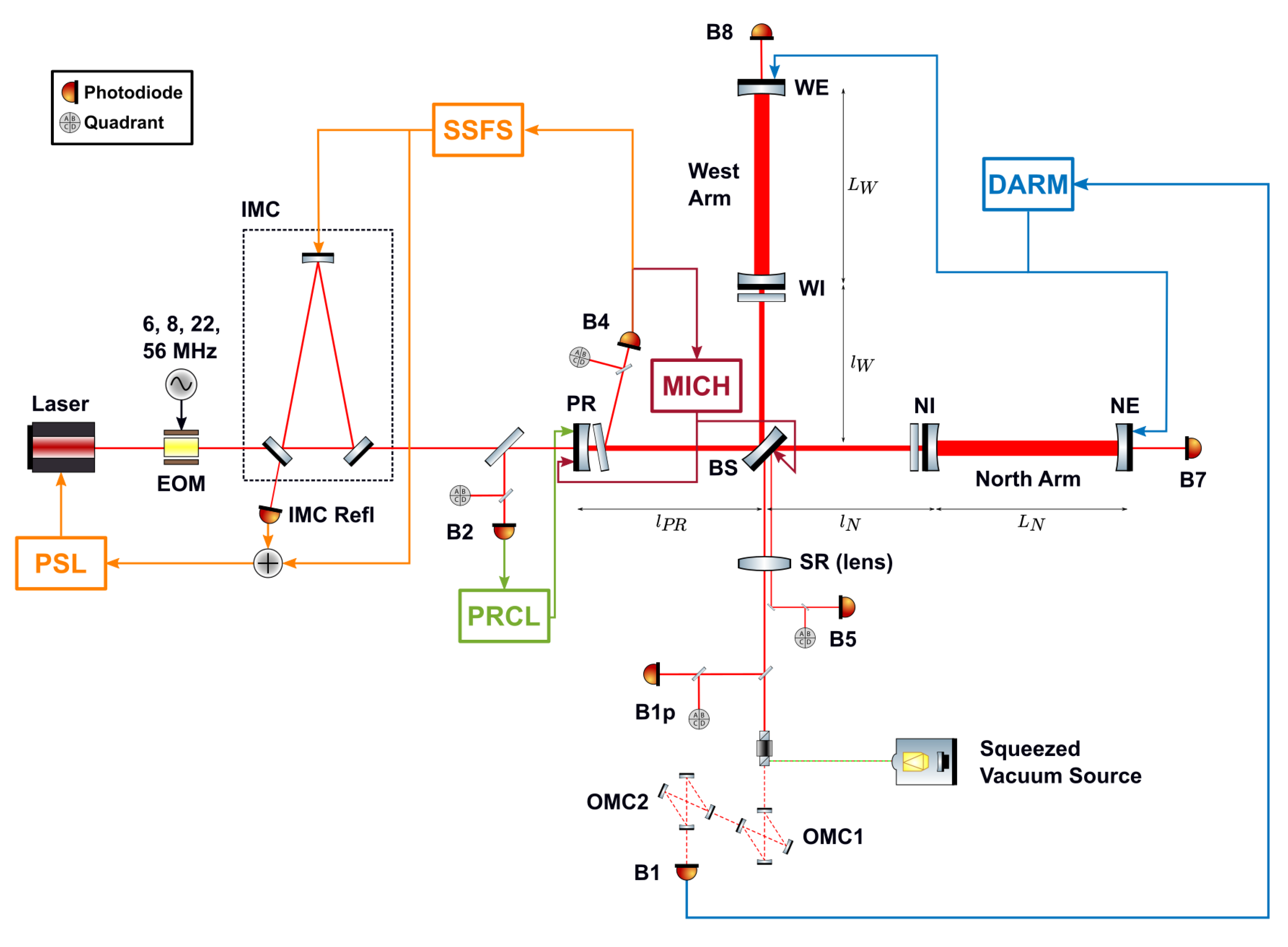
Section 1, a laser interferometer GW detector is a compound optical system which is based on the Michelson interferometer as its working principle, with in addition several technological improvements (like resonant optical cavities) which are useful to both increase its performance and to reduce some of the technical noises it is affected by. The optical scheme of Advanced Virgo in O3 is unchanged with respect to O2; it is pictured in
Figure 1 and a thorough description can be found in [
4].
Here we recall very briefly its main points: the several optical cavities, made by suspended mirrors, define several characteristic longitudinal degrees of freedom (DOF), which have to be kept in a definite working point via an active feedback control system; taking the Beam Splitter mirror (BS) as the origin of the coordinate system, such DOFs are the following (cf.
Figure 1):
MICH = , the length difference of the short arms of the Michelson, it defines the interference condition;
PRCL = , the Power Recycling cavity length;
CARM = , the Common, average length of the long Fabry-Pérot arm cavities;
DARM = , the length Difference of the long Fabry-Pérot arm cavities; this is the most important degree of freedom, as it is the one which is sensitive to the passage of gravitational waves.
The main longitudinal control technique of Advanced Virgo, which is used to control all the aforementioned DOFs, is the Pound-Drever-Hall (PDH) technique [
8,
9], and the control scheme does not differ from the one that was used in O2 [
4,
5]. This technique is based on the generation of radio-frequency sidebands, which are used to phase modulate the carrier light, and the demodulation of the photodiode (PD) signals at such frequencies; in Advanced Virgo the sidebands are generated via an Electro-Optic Modulator (EOM) and the characteristic frequencies are 6
, 56
(with the corresponding sidebands anti-resonant in the arms) and 8
(with the corresponding sideband completely reflected by the interferometer). Therefore, each DOF is sensed by a signal extracted from one PD (or, in general, by a linear combination of signals extracted from different PDs), demodulated at a given sideband frequency (or frequencies). The notable exception to this scheme is the sensing of the DARM DOF, which does not use a radio-frequency demodulated signal but a DC signal, due to the detection scheme used in 2nd-generation detectors, called
DC Readout [
2].
The sensing of the CARM DOF is instead peculiar for a different reason: one of the most sensitive sensors which is used for such DOF (B4 in
Figure 1) is equivalently sensitive to a common movement of the arm cavities lengths and to a change in the frequency of the main laser (i.e., frequency noise). For this reason such sensor is used with a nested control loop which acts on both the mechanical movement of the mirrors and the laser’s frequency; this latter loop is called Second Stage of Frequency Stabilization (SSFS) [
10].
For the longitudinal controls, the main novelty for O3 has been the introduction of feed-forward techniques, which are aimed to the reduction of noise couplings from a known source either directly to the DARM DOF, or to one of the auxiliary ones; while in the former case the benefit is evident, also in the latter case the reduction of such a noise coupling gives a benefit in the overall noise level of the DARM DOF since the main contributors to the DARM noise level are exactly the other longitudinal DOFs.
The two feed-forward techniques which are going to be presented here are the one devoted to the reduction of the PRCL noise from the SSFS error signal (the so-called PRCL to SSFS) and the one devoted to the adaptive reduction of the noise coming from the 50 main electricity line and affecting directly the DARM DOF (named Adaptive 50 Hz).
2.1. PRCL to SSFS Feed-Forward
The purpose of this technique is to reduce the noise coupling between two auxiliary DOFs, PRCL and CARM (in its control implementation, the SSFS loop), which is then propagated to DARM. The source noise is due to the residual longitudinal motion of the PR mirror, which is at least in part induced by sensing noise (above 10 ) caused by scattered light. Such noise is then propagated commonly inside the two arms, as they see the same disturbance coming from the input port of the interferometer; this common disturbance can be sensed by the B4 PD, which is a pick-off of the Power Recycling cavity and it is used to sense the SSFS.
The SSFS loop on its own is quite effective in reducing the frequency noise sensed by the B4 sensor, and it has 10 of Unity Gain Frequency (UGF), which is much higher than the UGF of all the other loops, which range between 10 to 100 of control bandwidth. Therefore, the residual frequency noise sensed by the B4 PD is quite low. On the other hand the PRCL loop, because of the residual motion of the PR mirror, induces a spurious signal on the SSFS sensor within the SSFS control bandwidth; therefore, the SSFS loop considers it as legitimate frequency noise and tries to correct it, actually doing the opposite and re-introducing this length noise as frequency noise.
For this reason, it was decided to implement a noise-cancellation feed-forward system which adds, to the SSFS controller, an additional term which depends on the PRCL loop and on the cross-coupling between the two loops. Such additional term is tuned in order to cancel the effect of the spurious noise.
More in detail, the coupling mechanism between two DOFs can be described in the following way: given a diagonal controller
C and a plant
P which is non-diagonal, i.e., it has cross couplings,
the two cross-couplings terms
e
are not controlled and cannot be suppressed. If instead one wants to reduce one of the two terms (for instance,
), the controller takes the following form:
In this case, the product
, which represents the coupled open-loop transfer function, is
and, in order to cancel the noise coupling term, the non-diagonal term of the controller is defined as
and
becomes
The stability of the loops is dependent on the eigenvalues of the matrix: given that is triangular, the eigenvalues are simply the diagonal terms. What happens is that one diagonal term (relative, in this case, to the PRCL loop) is modified by the introduction of this feed-forward control term, as it changes from being simply to the form , which changes, but not in a dramatic way, the shape of the PRCL loops itself.
The term
x can be found from quantities which are either known (
, the PRCL controller) or can be modeled (
and
) in frequency domain as optical transfer functions, with their overall gain measured with standard noise injections in the loops. From a procedural point of view, what is done is to take the correction of the PRCL loop, filter it following the shape of the cross-coupling term and then add it to the SSFS sensing matrix; the filter used to match the cross coupling term has the form depicted in
Figure 2.
The application of this
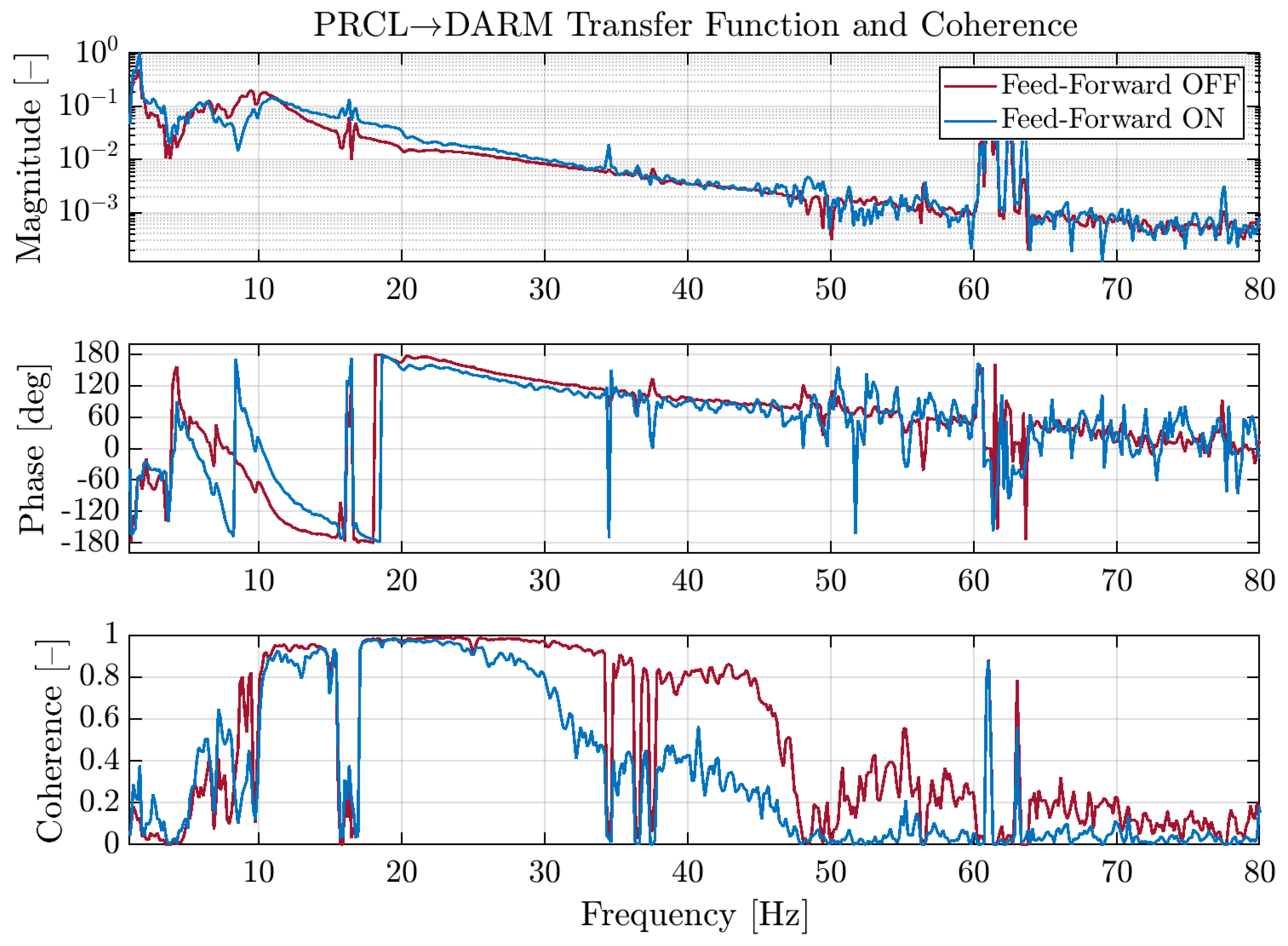
PRCL to SSFS feed-forward technique is appreciable in
Figure 3, where the transfer function and the coherence between the PRCL and the DARM DOFs are shown during two separate noise injections, in order to make a precise measurement of the coupling of PRCL to DARM: as it was explained in
Section 2, the reduction of the coupling between auxiliary DOFs does have an effect on the noise level of DARM as, for example in this case, the reduction of the PRCL contribution to the frequency noise level assures that the contribution to DARM of the SSFS itself is effectively reduced.
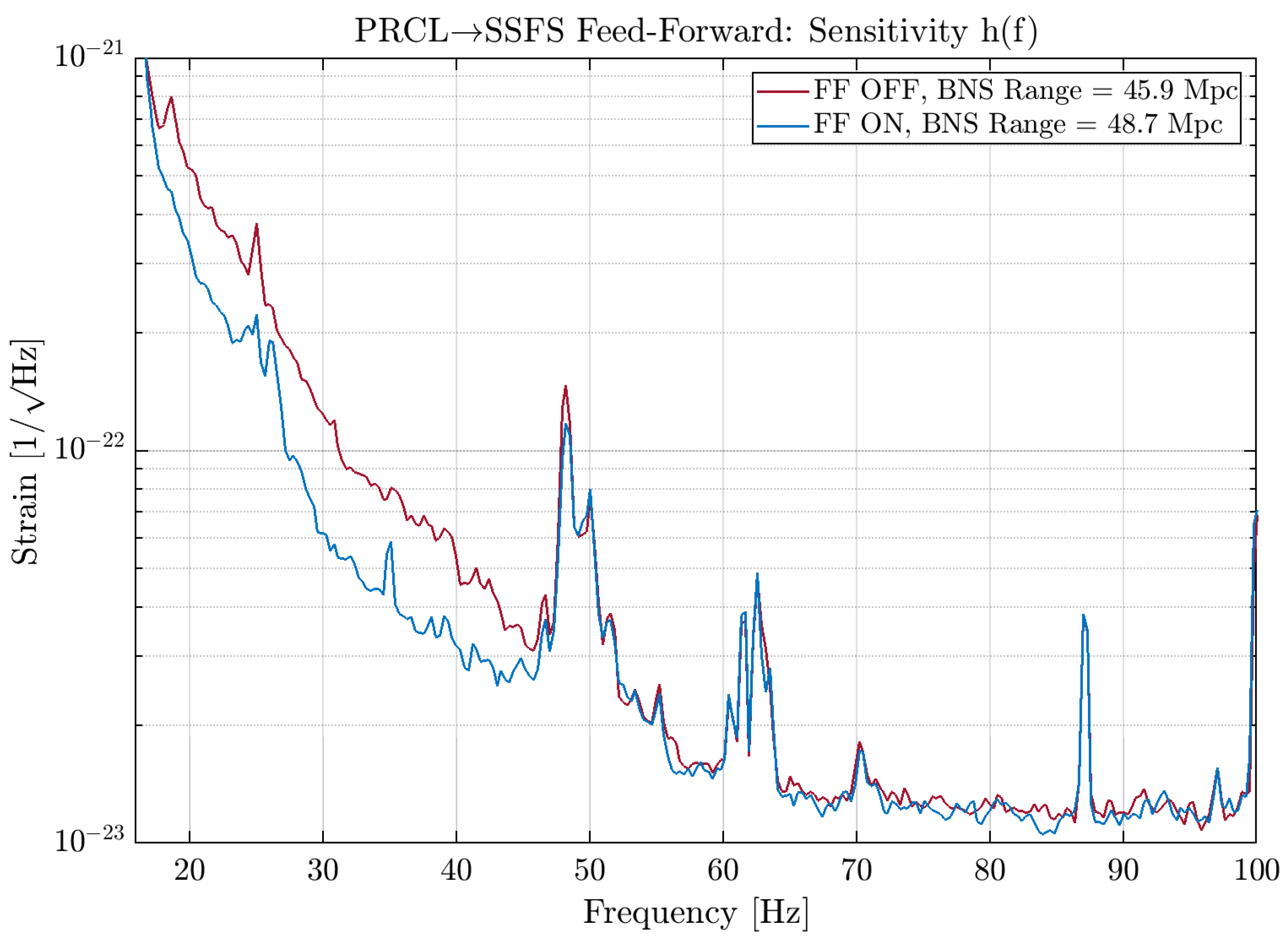
The effect of the feed-forward on the sensitivity curve
of the interferometer will be presented in
Section 4, which is devoted to the performance improvements brought by all the techniques described in this paper. In addition, future possible improvements can be done by reducing the PRCL control noise by mitigating the source of the noise and improving the roll-off of the control filter.
2.2. Adaptive 50 Hz Feed-Forward
The second feed-forward technique which was used for the longitudinal controls of Advanced Virgo during the O3 Run was devoted to the suppression of the noise line at 50
, which is due to the electrical mains. This control is quite different with the one described in
Section 2.1, as here the target is directly the primary DOF (DARM) and the disturbance is not coming from an auxiliary control loop but it is an independent, known noise source. In addition, the disturbance is not broadband, but theoretically it is at a very definite frequency.
In order for a feed-forward to be accurate, it is necessary to find a good witness of such disturbance, so that it can be used to build a viable error signal for the feed-forward itself; in this case, it was found that the probe of one of the three phases of the Uninterruptible Power Supply (UPS) system present in Virgo’s Central Building was a good candidate, so it was chosen as witness channel.
The working principle of this kind of control is the following:
the level of the 50 mains line is measured using, as a probe, one phase of the UPS system present in Virgo’s Central Building;
a gain and a phase are applied to the signal coming from the probe, in order to match the noise that is seen by the target channel, which is the main longitudinal degree of freedom, DARM;
in order to compute the correction, this quantity is filtered using a resonant filter with 50 as characteristic frequency: in this way, it is possible to avoid the introduction of additional noise (due to this control) at frequencies different from the target one;
the correction is then sent to the actuators (which are the coil-magnet pairs of the West Input (WI) mirror) in order to effectively cancel the effect of the noise at 50 directly in DARM.
One important point, which is crucial in determining the performance of the control, is the following: this feed-forward is
adaptive, meaning that the gain and phase which have to be found for a matching correction to be computed are not static, so two control loops are constantly
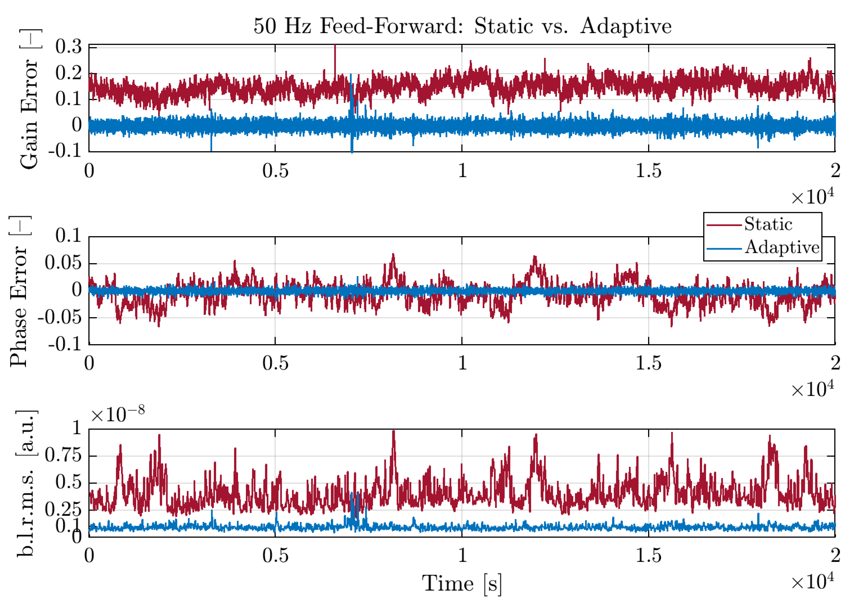
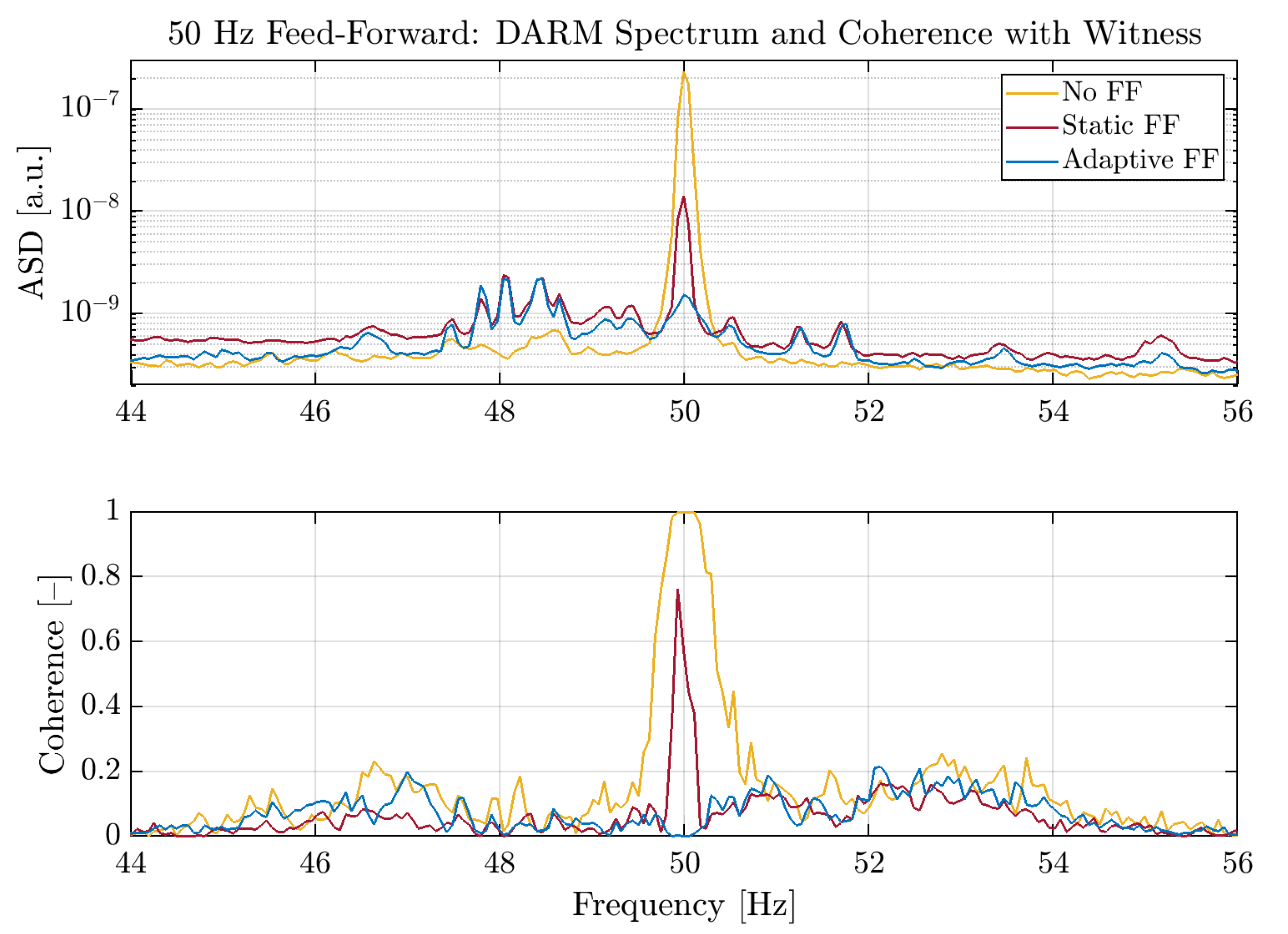
adapting online their value in order to follow any change of the noise coupling, which is not perfectly stationary itself. The error signals for these two loops (gain and phase) are the two quadratures of the demodulation of the DARM signal itself with respect to the witness, i.e., one phase of the UPS system of the Central Building. As it is shown in
Figure 4 and
Figure 5, using an adaptive strategy allows reducing the noise level, described by the band-limited root mean square (RMS) of DARM around 50
, with respect to the static case. Such strategy is also quite fast to engage (with a bandwidth of around 50
), as the loops converge rapidly (cfr.
Figure 5) while the band-limited RMS of the DARM DOF drops by two orders of magnitude with respect to the case with no feed-forward engaged.
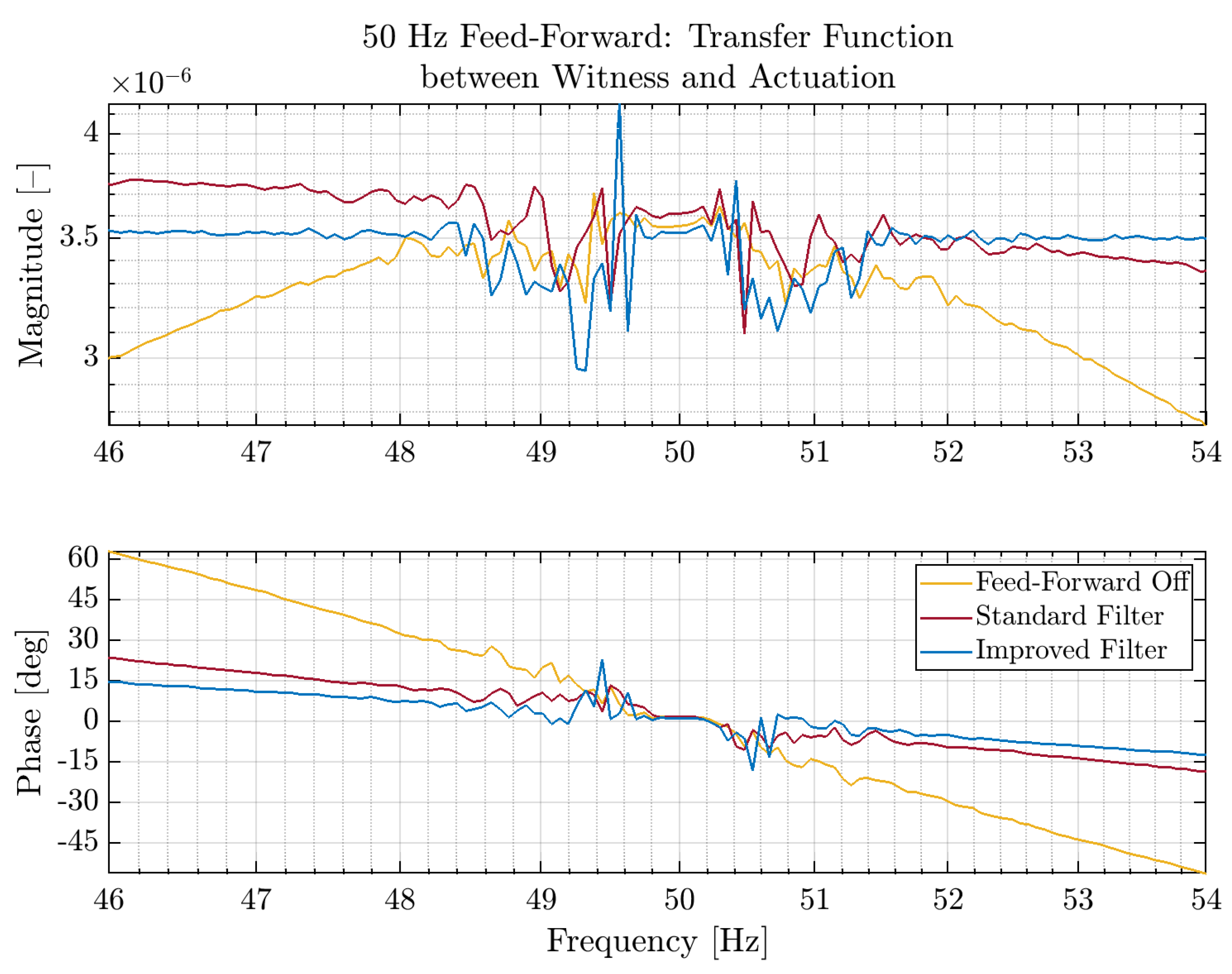
One other important point is to find the best possible match between the witness channel and the disturbance, i.e., having the transfer function between the two signals as flat as possible in the band of interest, as it is expected. This means that the information provided by the witness is replicated correctly with the actuation without distortions, and this provides two linked advantages:
it reduces the possibility to actually re-inject noise outside the narrow band of interest, as the feed-forward would try to subtract spurious, non-physical effects;
it allows reducing the Q factor of the resonant filter, resulting in a less narrow band on which it can operate.
Since the mains frequency is not perfectly stable on its own account but it has some jitter, having a larger band is helpful as it eases the requirements on the in-loop parameters of the adaptive feed-forward, as the frequency jitter of the disturbance directly affects the computation of the phase of the feed-forward. Moreover, the effect of the subtraction can be extended in a small band around the mains line itself.
This has been achieved, as shown in
Figure 6, where it can be seen that the transfer function has become very flat not only at 50
, but also in a non-negligible band around the mains frequency. The effect on the coherence with the DARM signal will be shown in
Section 4, which is devoted to the performance improvements due to the different techniques described in the paper.
3. Angular Control Scheme
For the interferometer to reach the maximum sensitivity, DARM residual motion must be kept below RMS. To accomplish this requirement, the Fabry-Pérot cavity length control is not sufficient, as also the mirrors angular stability plays a role.
All the mirrors are free to oscillate around their main axes. In particular, we define the x and y axes as the two perpendicular directions on the plane of the mirror Highly Reflective (HR) surface, with horizontal and vertical orientation respectively. Mirror oscillations around x and y are therefore called and .
A first mitigation of the seismic noise is obtained by hanging each mirror to the so-called
Superattenuator [
11], a long chain of pendulums which provides a seismic noise suppression in the beam direction of
, where
f is the frequency and
n the number of pendulum stages. This yields a passive overall noise reduction by a factor
starting from a few
.
A misalignment of the cavity mirrors can induce a tilt/shift of the optical axis with respect to the beam direction. It can be shown [
12] that while the geometrical displacement can be compensated by the longitudinal lock, on the other hand the first-order transverse optical modes can be excited and therefore spoil the destructive interference of the beams at the interferometer output. Furthermore, being the mirrors spherical, if the optical axis does not overlap with the mirror center, a coupling with the longitudinal DOFs of any residual angular motion is observed, with a subsequent worsening of the detector sensitivity.
As explained in
Section 1, in Advanced Virgo, where about 25
of input power are injected in the interferometer, three main optical resonators can be identified: the two 3
arm cavities, with a Finesse of about 460 and a circulating power of about 130
, and the Power Recycling cavity, the additional compound optical resonator composed of the PR mirror on one side and the two arm cavities input mirrors on the other side. This latter cavity, also referred to as CITF (
Central Interferometer), has a much lower Finesse (around 60) with respect to the arm cavities with a total circulating power of about 1
.
Second generation interferometers, with respect to first generation, have to deal with an additional effect due to high circulating power: the radiation pressure effect. If a static misalignment is present, the optical axis does not hit the geometrical centers of the mirrors. As a consequence, the laser beam exerts on them a torque with a force proportional to the circulating power.
Such effect can be modeled as an optical spring connecting the cavity mirrors. This optically induced torsional stiffness changes the cavity mechanical transfer function as a function of the circulating power, and can be even larger than the stiffness of the mirror suspensions.
Radiation pressure effects can be described in terms of the torsional stiffness matrix, which in turn depends on the cavity
g-factor and on the circulating power. This matrix becomes diagonal in the normal mode basis, which are the
plus (+, which increases the suspension frequency and makes the mode stiffer) and
minus (−) DOFs [
13]. It can be shown [
13] that the resonance frequency of the latter mode can become imaginary: in this condition, the system becomes unstable and the control filter has to be properly shaped as to guarantee the stability [
14].
In the arm cavities, where the largest amount of power is stored, the radiation pressure effect is higher, while mirrors in the central interferometer are less concerned.
Both slow drift and faster oscillations of the cavity mirrors must be kept under control: this determines the bandwidth of the control loops, which should range from DC up to a few . The actuation is performed using the second to last stage of the Superattenuator, called marionette: this allows a larger force to be driven while filtering the correction signal by a pendulum stage before reaching the mirror, reducing the actuation noise.
To guarantee an optimal working point for the interferometer, the alignment of two angular DOFs for each of the six mirrors has to be controlled, aside from the input beam direction tilt and shift. To fulfill the requirements, the estimated needed precision is hundreds of
for the (−) modes, tens of
for the PR and BS mirrors and reduces down to a few
for the (+) modes [
15,
16].
3.1. Degrees of Freedom Definition and Interferometer Sensors
To better describe the alignment control scheme of the Advanced Virgo detector, it is convenient to define the interferometer angular DOFs.
In the Power Recycling cavity, the radiation pressure is not strong enough to couple the angular DOFs, thus PR and BS can be treated independently. Concerning the arm cavities, the radiation pressure effect plays a very significant role, resulting in an optical spring between cavity mirrors. Hence, a basis of common and differential DOFs, both (+) and (−), is more suitable for the arm cavities misalignment description as it is the basis which diagonalizes the sensing.
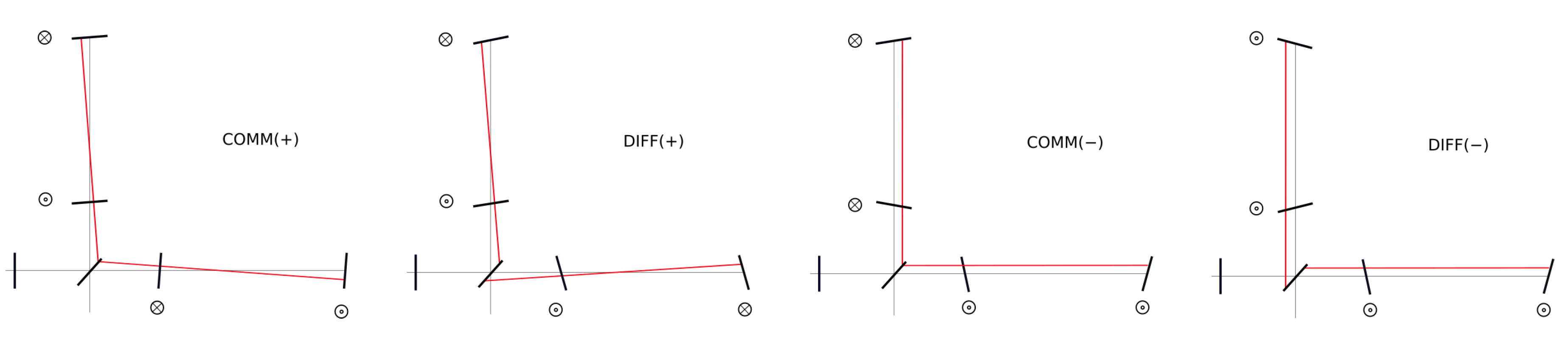
The four DOFs (effectively eight if the rotations around
x and
y axes are considered) are depicted in
Figure 7. In particular:
COMM(+): common tilt of the arm cavities resulting in the two beams recombining in the same spot on the BS;
DIFF(+): differential tilt of the arm cavities resulting in two spots recombining on the two opposite sides of the BS;
COMM(−): common shift of the arm cavities resulting in the two beams recombining in the same spot on the BS;
DIFF(−): differential shift of the arm cavities resulting in two spots recombining on the two opposite sides of the BS.
In addition to the optical cavities, also the input beam tilt and shift with respect to the interferometer plane have to be controlled. However, only one of them (tilt) is kept in loop, since the local controls (see next paragraph) for the shift are compliant with the accuracy requirements.
Different types of controls are used for the interferometer alignment:
Local Controls—A first stage of control on the mirrors is performed by engaging the so-called local controls. The error signals are obtained with a system of optical levers, a setup made of a Superluminescent Diode (SLED) hitting the mirror and focusing on a Position Sensing Device (PSD), able to monitor the angular and longitudinal position of the mirrors. The local controls can achieve a precision of ≈/ RMS for the mirror angular control. These sensors are ground-based and can only provide a local reference. Optical levers noise has the advantage of being fairly flat out of the control bandwidth (about 10 ): its level is about / at the marionette level and it is filtered down by an additional factor due to the last pendulum stage before reaching the mirror.
Dithering Control—The basic principle of the dithering technique is that a coupling between longitudinal and angular DOFs is observed if the cavity axis does not hit the mirror rotation center of actuation [
6]. The error signal is obtained, once the longitudinal DOFs are locked, by exciting both angular DOFs (
and
) of each test mass at a determined frequency, all different for each DOF and each test mass (below 10
for arm cavity mirrors). Then the cavity longitudinal correction is demodulated at the same frequency: the amplitude of the signal is thus proportional to the angular-to-length coupling. This allows obtaining a set of angular signals suitable to sense mirror angular displacements. To cancel them, the mirrors angular position which minimizes the coupling is chosen. This technique allows achieving a good tuning of the resonators working point, although its noise performance is not good enough to meet the noise and accuracy requirements for the most critical DOFs, namely the (+) modes and the central interferometer angular modes. This is due to the fact that the dithering error signal is blended at 50
with the local control signals, which are much noisier than the QPD signals, used for the Full Bandwidth Global Control, which is described below.
Full Bandwidth Global Control—The
Global Alignment control takes advantage of the
Ward technique [
17], which exploits the modulation frequencies used for the PDH technique in the longitudinal lock [
8]. We recall (cf.
Section 2) that for the longitudinal lock the carrier light is phase modulated at three different frequencies: 6
and 56
, which are resonant in the CITF and anti-resonant in the arms, and 8
, completely reflected by the interferometer. In presence of a misalignment, the off-axis modes of carrier and sideband fields are reflected and are sensed by a QPD, which has four separated areas to be sensitive to high order modes power distribution. Besides the demodulated signals, also the QPD DC signal is used for the angular control, as it provides a good indication about the beam position. QPDs are the most sensitive sensors, as they are able to measure the relative displacement between the beam and the cavity axis. Moreover, their noise level is much lower than the one of the PSDs, which allows using high loop gains avoiding to spoil the sensitivity by re-introducing control noise.
In the final interferometer configuration (science mode), the most critical DOFs are controlled using this kind of sensors, while the others make use of a mix of signals coming from optical levers and dithering.
3.2. Alignment Control Evolution
As described in [
4], the interferometer working point is reached through the
Variable Finesse technique. This lock acquisition strategy consists of different steps, which will be briefly recalled in the next subsections. Since each step requires a suitable alignment accuracy, different alignment schemes are applied.
3.2.1. Phase I: Arms Drift Control
In the first step of the lock acquisition, all the mirrors are under local controls. The PR is misaligned, so as to avoid the effect of the Power Recycling cavity, the two Fabry-Pérot arm cavities are brought to resonance and the MICH DOF is controlled at an intermediate interference condition (half fringe). In this configuration, shift and tilt of the input beam with respect to the interferometer plane have to be controlled, together with optical axis shift and tilt of the two arms, in a single cavity basis.
The input beam is controlled through the
Beam Pointing Control system [
18], which allows reaching a shift accuracy of 20
RMS and a tilt accuracy of
RMS.
The arm cavities optical axes are geometrically centered through the dithering technique described in
Section 3.1. The same technique is also applied to maximize the overlap between input beam direction and arms optical axes, which is the tilt of the input beam with respect to the interferometer plane. To do this, the Anti-Reflective (AR) surface strong curvature of the PR mirror (
) is exploited: indeed, shifting the PR along horizontal and vertical directions, a tilt to the beam not hitting the PR mirror center is applied along
and
, respectively. Dithering of PR mirror
x and
y position and demodulating the line in the arm transmitted power yields an error signal for the mutual tilt between input beam and cavity axis: the optimum point is obtained for the maximum arm transmitted power. This procedure is well suited for the North arm cavity, which is in the direction of the beam transmitted by the BS mirror, while the pointing to the West arm cavity depends on the BS orientation. To achieve an equally good tuning also for the West arm cavity, the dithering is applied also to the
and
of the BS mirror, in order to steer the beam toward the West cavity. The error signal for the West arm alignment is therefore achieved by demodulating the BS angular lines in the West arm transmitted power. The input beam impinging on the cavity is then steered by translating the PR mirror, for North and West cavities, and tilting the BS mirror, for the West cavity.
3.2.2. Phase II: PR Mirror Alignment and Variable Finesse
During the second phase of the lock acquisition, the PR mirror is aligned and the Power Recycling cavity becomes fully effective; then, the Michelson fringe is reduced to attain the destructive interference working point (dark fringe). These operations result in an enhancement of the interferometer circulating power.
In this phase the drift control is switched off, as it is affected by the power increase in the arms. This is possible because any drift of the cavity mirrors would be too slow with respect to the duration of the fringe reduction procedure.
On the other hand, being the Power Recycling cavity very critical because of its small Gouy phase [
1], the PR mirror optimal working point must be reached and kept throughout the whole procedure; therefore, its angular control is performed by using a QPD in reflection of the interferometer (B2 QPD, see
Figure 1 in
Section 2), demodulated at 8
.
This alignment scheme is kept until the last step before going to dark fringe: just before the interferometer reaches the dark fringe condition, this alignment is switched off. As soon as the dark fringe configuration is reached and the power circulating in the arms is not changing drastically anymore, the drift control is immediately turned back on, but only for the four Fabry-Pérot mirrors.
3.2.3. Phase III: Final Working Point Angular Control
So far we have described the alignment scheme in the mirror basis. However, once the dark fringe configuration is achieved, the interferometer signals are much more entangled. In the final working point, a distinction can be made between the Power Recycling cavity alignment loops and the arms control loops. For the latter, it is convenient to switch to the
Common and
Differential basis described in
Section 3.1. In the dark fringe configuration, the interferometer provides very good error signals for the COMM(+) and DIFF(+) DOFs. In particular, a good accuracy and a high gain are required for the destructive interference to be as good as possible: this is obtained by using the B1p QPD error signals demodulated at 56
, and an accuracy of about 1
is achieved. Furthermore, the beam spot residual motion has to be minimized on the test masses, and this is controlled with the COMM(+), which uses the DC of the B5 QPD as error signal. On the contrary, in this configuration, interferometer signals are not good enough to provide a sensitive error signal for the DIFF(−) and COMM(−) DOFs, and the drift of such DOFs is controlled with the dithering technique. Finally, in the central interferometer, B5 QPD signals demodulated at 56
are used for PR and BS angular controls. Furthermore, the PR horizontal and vertical centering, which act on the input beam tilt, are controlled using the B2 QPD demodulated at 8
. The interferometer plane is defined by the COMM(+) and the two (−) modes reference.
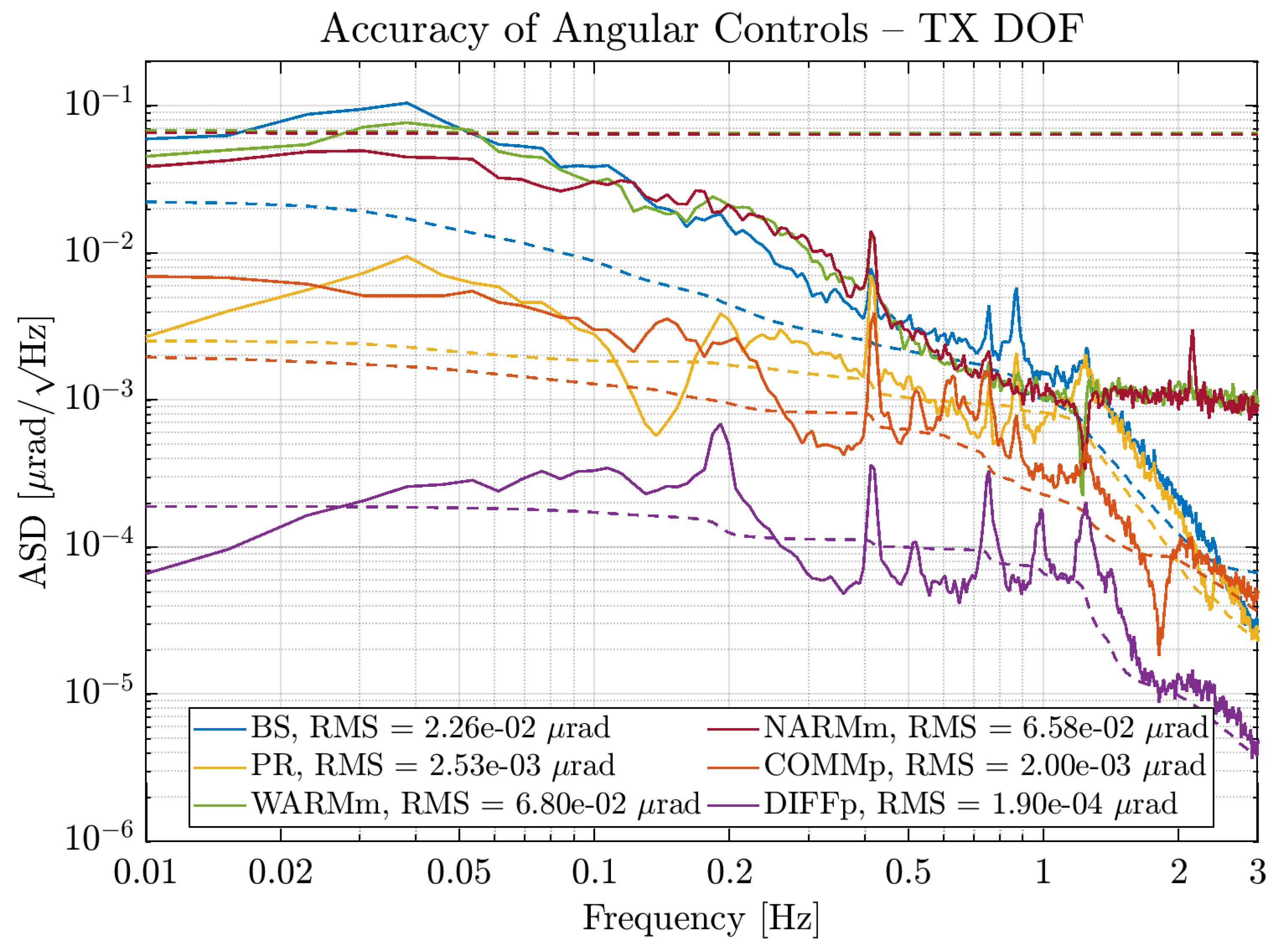
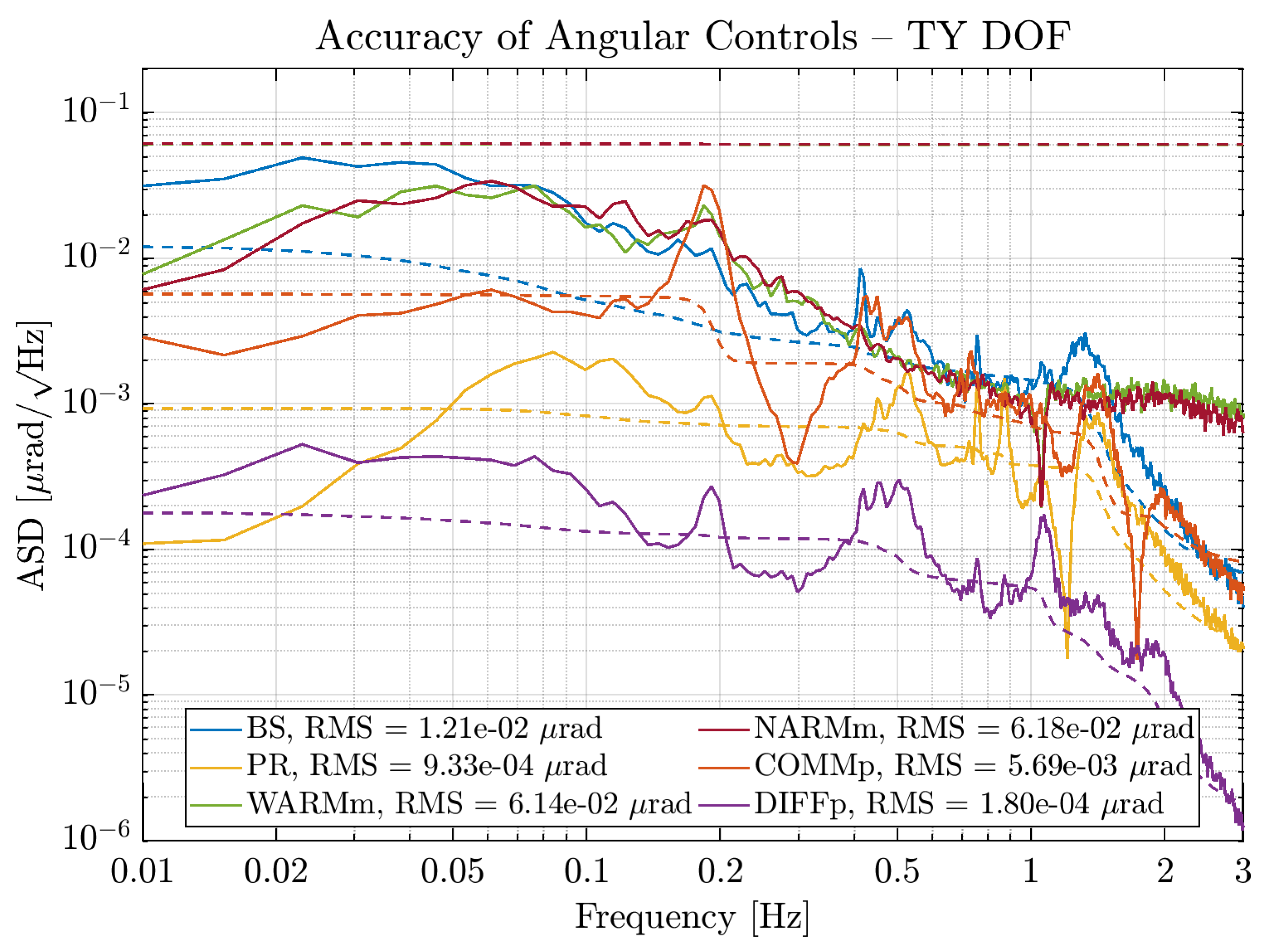
The overall accuracy of the angular controls can be observed in
Figure 8 and
Figure 9, for the
and
DOFs respectively; in order to reduce the software communication paths between the suspensions, the two (−) DOFs are reconstructed in the North/West single cavity bases.
3.3. Phase Noise Subtraction
The QPD signals demodulated at 56
show excess of phase noise that is added in the digital demodulation process, which can be summarized as follows. The electromagnetic field of the light impinging on a PD can be written as
where
,
, and
are the complex amplitudes of respectively the carrier, lower sideband and upper sideband. The electric signal produced by the PD is proportional to the power impinging on the PD, which is
where
,
and
are the powers of the carrier, 1 and 2 order sideband fields respectively.
The digital demodulation process consists of multiplying the signal digitized at 400 with a sine and cosine at the sideband frequency and taking an average with a sampling frequency of 1 to obtain the and signals.
The generated sine and cosine signals have also an error
in the phase compared to the modulation imposed on the laser beam. That phase error is predominantly due to a digital timing jitter, hence the phase error can be written as
. This results in the two quadrature signals
and
to be of the form
with a spurious signal created in both quadratures by the phase noise
. The coupling of the phase noise depends on the signal in the quadrature, i.e., for
the noise coupling is proportional to the value of
and vice-versa.
However, the same timing jitter
is also affecting the signal demodulated at twice the sideband frequency (
2f signal):
which yields a measure
. By rotating
by the
angle we obtain
which replaces the demodulation phase noise
by the
2f signal phase
.
Moreover, the dominant contribution of the timing jitter is common to all PDs and QPDs situated on the same bench, as this noise is added when propagating the information on the timing to a given bench. Hence any PD signal can be used to correct the demodulation phase of all other PDs.
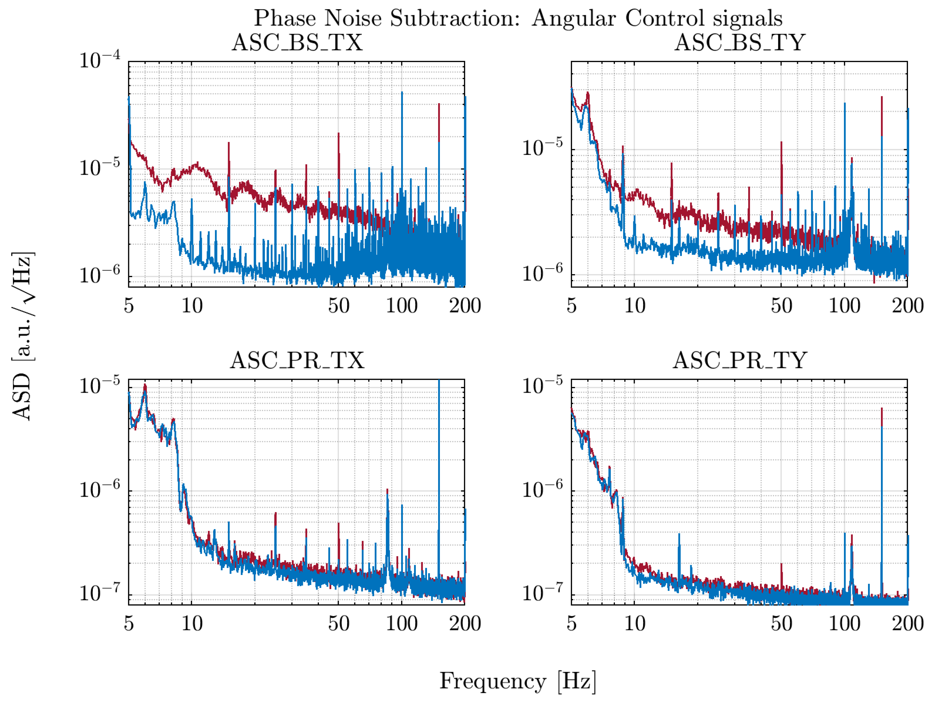
In practice, at the end of the second part of O3 (named O3b) the
2f signal of the light rejected by the Output Mode Cleaner (OMC) was used to correct the demodulation phase of the B5 and B1p QPDs. The correction is done separately for each segment of each quadrant. The effect on the alignment error signal noise can be seen in
Figure 10, which compares data in the same lock of the interferometer before and after applying the phase noise correction. Phase noise creates characteristic bumps in the spectrum, that are especially visible in the BS
signal (ASC_BS_TX), due to the larger offset in the signal in its quadrature. A reduction in this noise of up to a factor 10 is observed.

 ,
, 


