Determination of the Preload of Bolts for Structural Health Monitoring of a Multi-Bolted Joint: FEM Approach


1
Faculty of Mechanical Engineering and Mechatronics, West Pomeranian University of Technology in Szczecin, 19 Piastow Ave., 70-310 Szczecin, Poland
2
Faculty of Mechanical Engineering and Robotics, AGH University of Science and Technology, 30 Mickiewicza Ave., 30-059 Cracow, Poland
*
Author to whom correspondence should be addressed.
Lubricants 2022, 10(5), 75; https://0-doi-org.brum.beds.ac.uk/10.3390/lubricants10050075
Submission received: 11 March 2022
/
Revised: 5 April 2022
/
Accepted: 15 April 2022
/
Published: 19 April 2022
(This article belongs to the Special Issue Design for Tribology: Theoretical and Practical Assessment in Modern Mechanical Components)
Abstract
:The reliability and safety of bolted joints is one of the crucial engineering problems during design of mechanical structures. In this paper, finite element method was used to investigate an asymmetrical, seven-bolted joint. The modelling takes into account the phenomenon of friction and the mechanics of contact between the joined elements. The bolts were preloaded using two different approaches: single and multi-pass. The damage of a bolt was simulated by its removal from the model. The conducted research showed influence of the number of preloading passes and its order on the forces acting in bolts both before and after damage. The obtained results were validated by experimental tests and presented as force diagrams for all investigated cases.
1. Introduction
Human losses are often caused by undesirable processes and events occurring in technical systems. This is the reason why engineers currently focus a great deal of attention on the reliability and safety of structures that were designed and function in the human environment. These activities, in relation to already maintained structures, consist of health monitoring of various joints. This applies especially to systems with such structural nodes as bolted [1,2], riveted [3,4], or welded joints [5,6]. These issues are commonly defined as structural health monitoring (SHM) [7].
One of the most interesting issues in terms of SHM of bolted joints and bolts is their analysis when the load capacity of chosen fasteners is lost. Thus far, the results of several experimental studies on this subject have been published. Yan et al. [8] presented an experimental validation of a damage detection method on a full-size truss supporting road signs. The authors considered the loss of all bolts in one of the flange joint in this truss as one of the simulated damages. Similar studies but related to lattice towers were reported by Pérez et al. [9]. Pham and Hancock [10] and Pham et al. [11] studied the deformations of joints between beams and channels for different bolt systems. Martowicz et al. [12] discussed the effectiveness of the structural health monitoring system based on the electromechanical impedance for damage detection in a laboratory section of a bolted pipeline. For the same purpose, Thien et al. [13] proposed the use of macro-fibre composite transducers. Blachowski et al. [14] used modal and ultrasonic approaches for structural damage detectability in the case of a flat steel frame composed of beams joined by bolted joints. They simulated damage to the frame by removing some bolts from a given structure. Li and Hao [15] monitored the condition of the bolted joints in a model of a truss bridge under the removal of chosen bolts. Similar studies but for different types of bridges were reported by Beskhyroun et al. [16,17], Kromanis and Kripakaran [18,19], Kunwar et al. [20], and Whelan and Gangone [21]. Detection of loose bolts in a complex structure with a vibro-acoustic sensor array was presented by Becht et al. [22]. Grzejda and Parus [23] assessed the health of a selected multi-bolted joint after removing one or two bolts.
Several other papers were dedicated to FE-modelling of phenomena occurring in bolted joints influenced by fastener damages. Rucka et al. [24] applied guided wave propagation in diagnostics of steel-bolted bridge components. Qin et al. [25] performed a quasi-static finite element analysis of a typical disc-drum connection used in rotors of large rotating machines in the condition of removing some bolts from the connection model. Blachowski and Gutkowski [26] examined the variability of the connection stiffness caused by the damage of several bolts and its impact on the displacements in the case of a selected telecommunication tower. Patil et al. [27] presented the results of a transient analysis of a frame with bolted connections after removing one of the bolts, while Hasni et al. [28] described structural health monitoring of a steel frame in which the damage was introduced by creating cracks on its structural members and loosening the bolts.
The conducted paper review revealed gaps in the assessment of multi-bolted joints on the basis of modelling approach. This paper contributes to fill these gaps. The paper concerns a multi-bolted joint, the experimental tests of which have been described in [29,30]. The novelty in relation to the previous articles cited above is that in the current paper, an asymmetrical connection was modelled. The calculations were made using the finite element system called Midas NFX 2020 R2. The finite element method (FEM) was chosen as the analytical tool because it is a very useful method of engineering calculations [31,32,33]. The results were verified by means of experimental tests carried out with the use of resistive strain gauges [34,35,36,37].
The structure of the paper is as follows: Section 2 focuses on the description of the geometry of the tested multi-bolted joint, while Section 3 describes the test procedure, paying attention to the details of the preloading methods and simulated damage scenarios of the tested multi-bolted joint. Section 4 presents the FEM-based model of the tested multi-bolted joint. Section 5 focuses on the research findings and their discussion. Section 6 provides some additional conclusions from the research.
2. Physical Model of the Joint
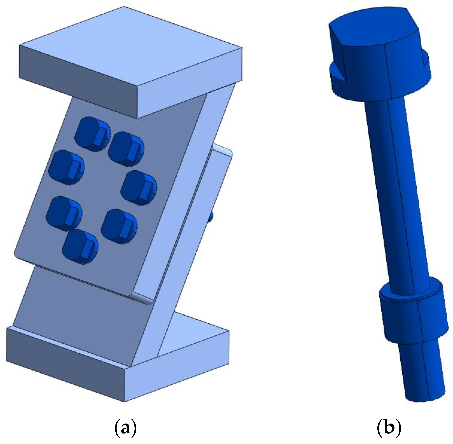
The subject of the analysis was the multi-bolted joint presented in Figure 1a.
The tested assembly was made of a pair of plates joined with i M10 × 1.25 fasteners shown in Figure 1b (for i = 1, 2, …, 7). The geometrical model of the fasteners consisted of a bolt and a nut merged as one solid [38].
The joined plates were welded to the top and bottom bases. The thickness of the joined plates and the bases was equal to 28 mm. The joint was tilted to the horizontal plane at an angle of 60° [39]. The total height of the assembly was approximately 266 mm. The plates and the bases were made of 1.0577 steel. After machining, the bolts and nuts were tempered to achieve the characteristics for the class of mechanical property 8.8 and 8, respectively.
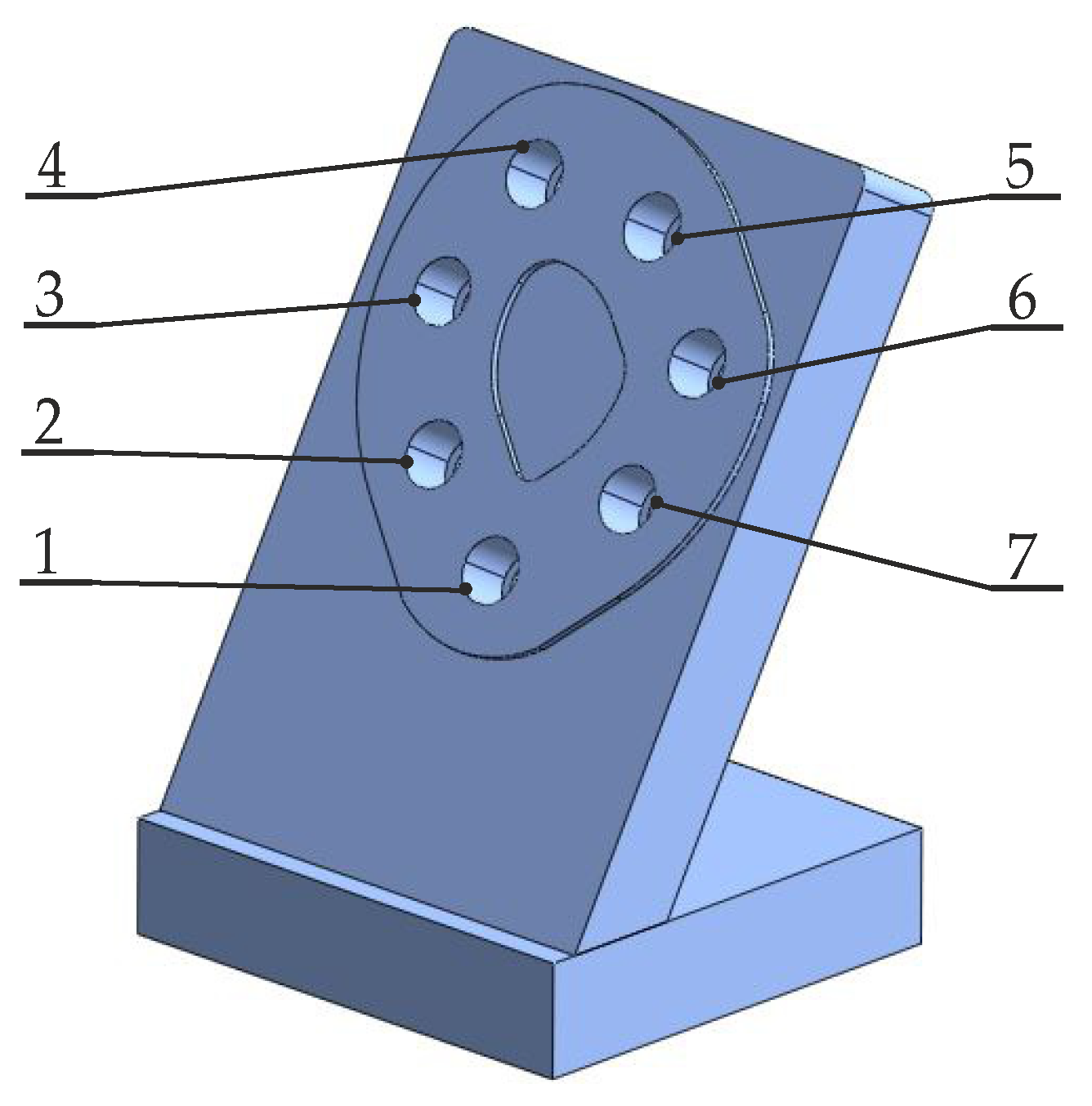
Figure 2 presents the contact surface area between the joined plates and the assumed numbering of the bolts. This area fits in a circle with a radius of 90 mm, and its outline does not exceed 90 cm2.
3. Research Procedure
The research was divided into the following stages:
The level of the bolts preload Fp was set at 22 kN on the basis of PN-EN 1993-1-8 [40] and the analysis of the resistance to surface pressure of the contact between the nuts and the lower joined plate.
4. FEM-Based Model of the Joint
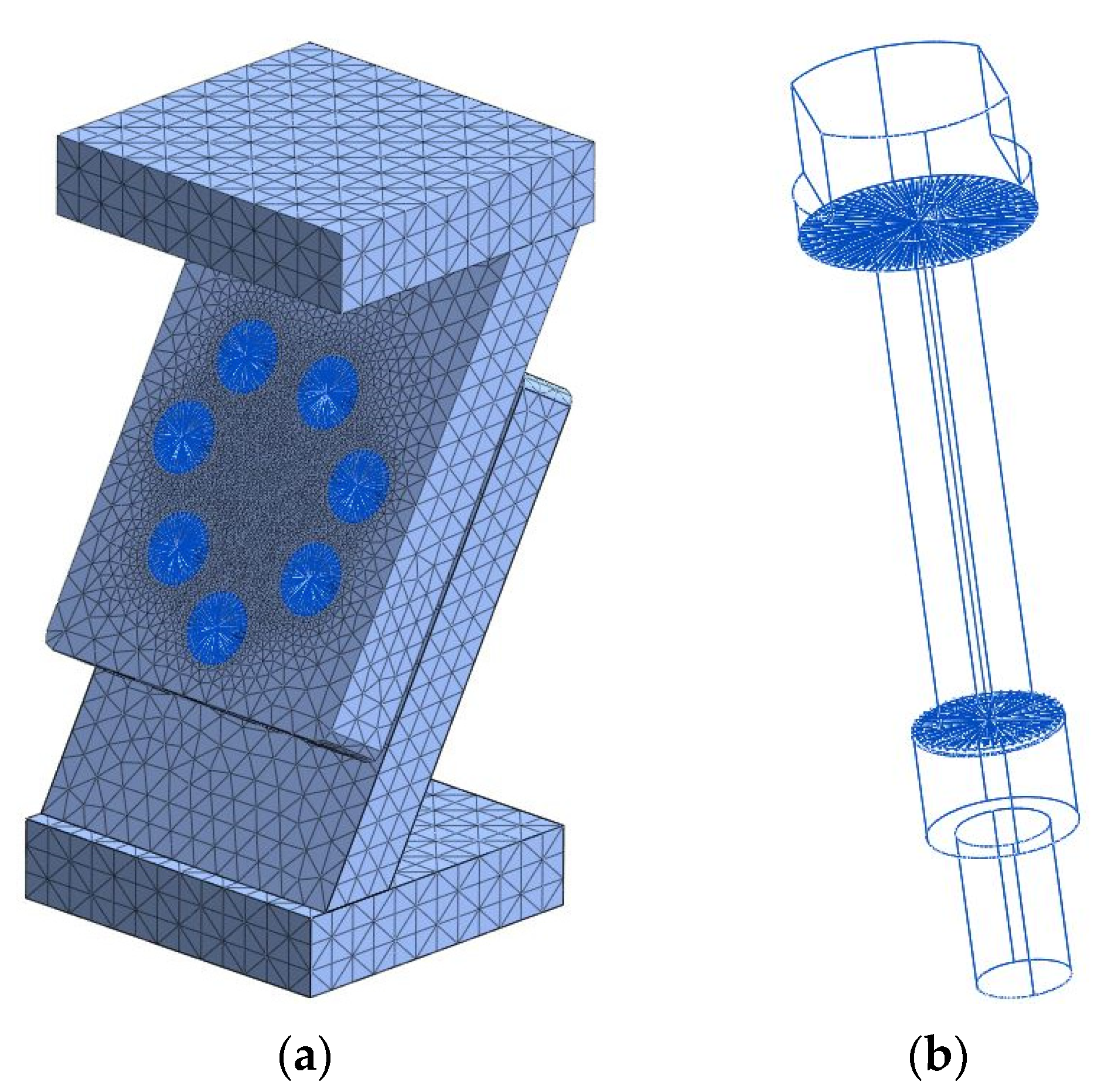
Using the tools available in the finite element system called Midas NFX 2020 R2, a multi-bolted joint model was built as shown in Figure 3. The joined elements were divided into 3D finite elements, while the fasteners were modelled as flexible beams with rigid heads and nuts [41,42]. In engineering modelling, the assumption of full rigidity of selected elements of a given model is often used [43]. All connection parts were assigned the properties of isotropic linear steel materials.
The rough contact between the joined plates [44,45] was modelled using the general surface-to-surface contact elements. They enable nonlinear analysis taking into account the possibility of separation of the joined plates in the normal direction and the occurrence of sliding in the tangential direction. The elements used in the contact model are typical and applied by many researchers without analysing the influence of the nonlinearity on the bolted connection model [46,47,48]. Nevertheless, it is also possible to analyse this influence [49].
The following values of the contact layer parameters were adopted:
- Normal stiffness factor equal to 10;
- Tangential stiffness factor equal to 1;
- Coefficient of static friction for a pair of ground surfaces equal to 0.14 [50].
Welded-type contact elements were used between the plates and the bases, preventing the elements from moving relative to each other in any direction.
The multi-bolted joint model was created with a total of 78,750 elements and 133,162 nodes. The maximum dimension of the side length of a finite element in the mesh does not exceed 10 mm. The mesh was considerably densified at the point of contact between the joined plates and at the point of contact between the fasteners and the joined plates [51,52]. The model was constrained by restraining all degrees of freedom on the underside of the bottom base. The preload of the bolts was applied via the “pretension” function built into the Midas NFX 2020 R2 system.
5. Calculation Results and Discussion
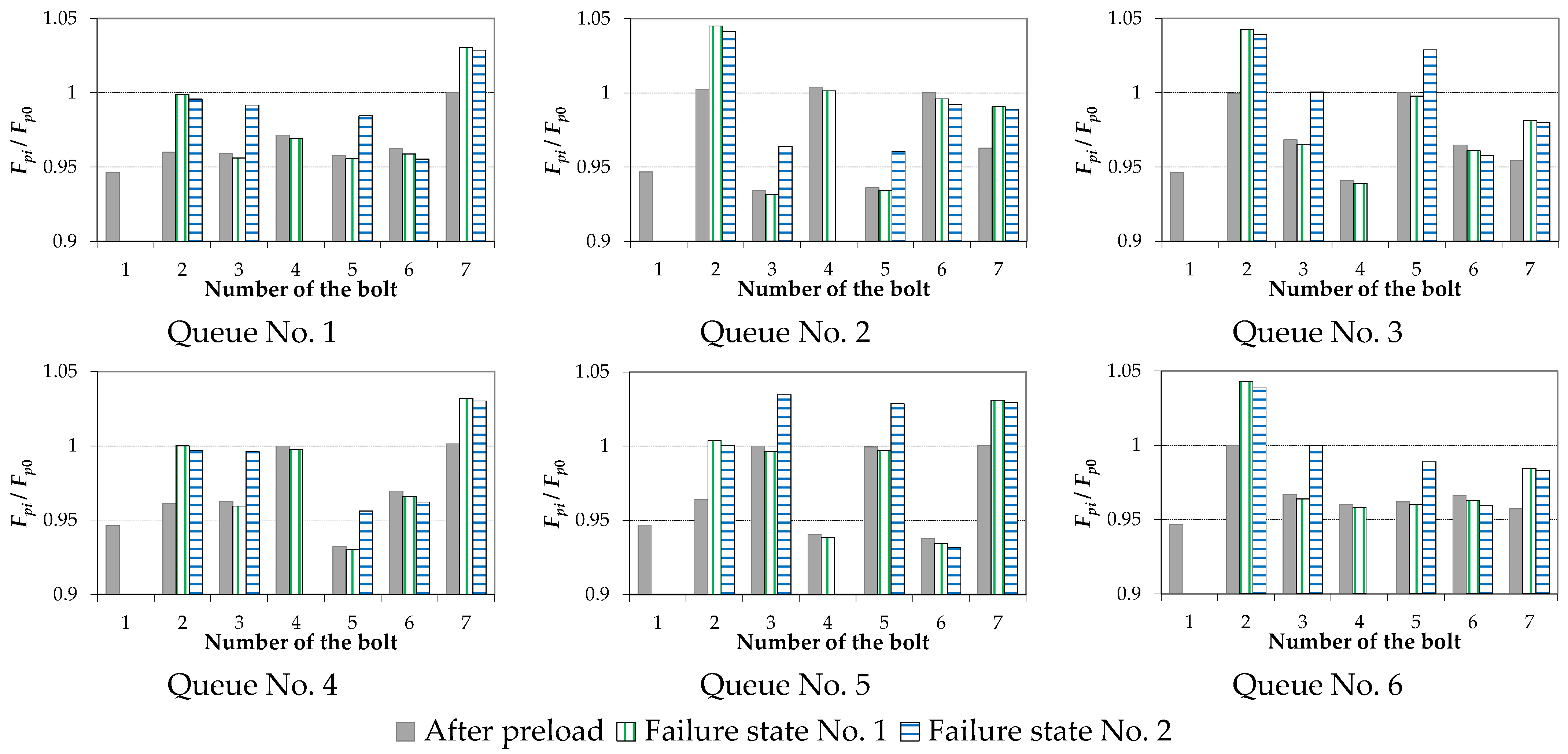
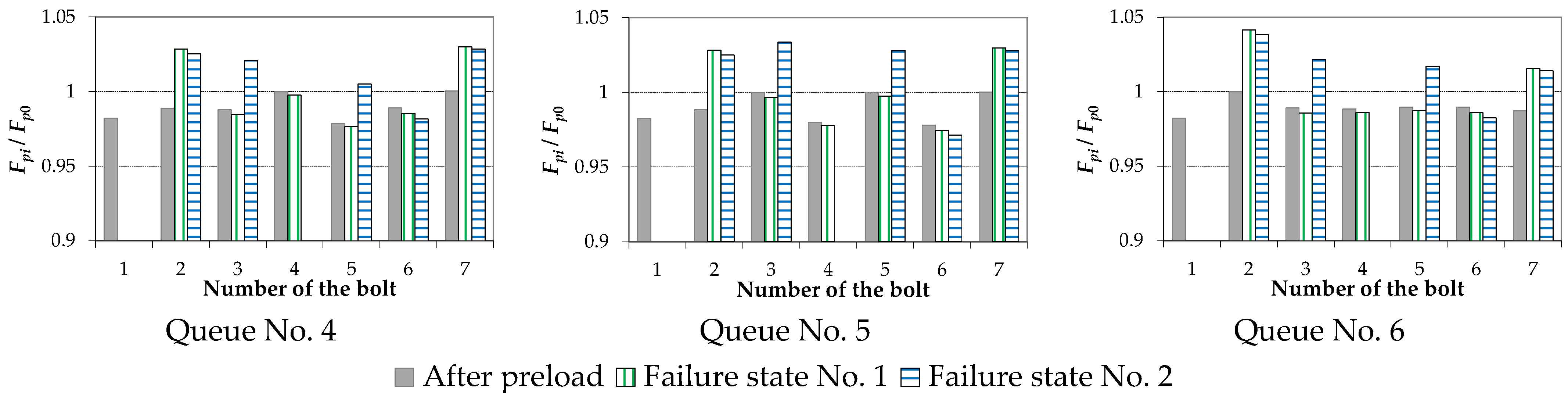
The charts of forces in the bolts Fpi normalised in relation to the value of the initial force Fp0 achieved in single-pass preloading of the joint for the assumed damage states of the bolts are presented graphically in Figure 4. Analogous charts for multi-pass preloading of the joint are shown in Figure 5.
- It was confirmed, as in the case of experimental tests [23], that in the damaged state of the joint, the largest increment of the force occurs in two bolts closest to the damaged one.
- The variability of the force chart in the bolts after the joint damage is determined by the order in which the bolts were preloaded.
The quantitative analysis of the results shown in Figure 4 and Figure 5 was carried out using the Z1 indicator, defined as follows:
where is the force in the bolt No. i in the analysed force chart at the end of the preloading process, and is the force in the bolt No. i at the analysed state of the joint damage.
The maximal Z1 indicator values received for respective methods of preloading and the states of the joint damage re shown in Table 4. To sum up its analysis, it is stated that the maximal force changes in the bolts caused by the introduced damage states were not influenced by the number of passes and the order of preloading. The differences variated between 3.17 and 4.28%.
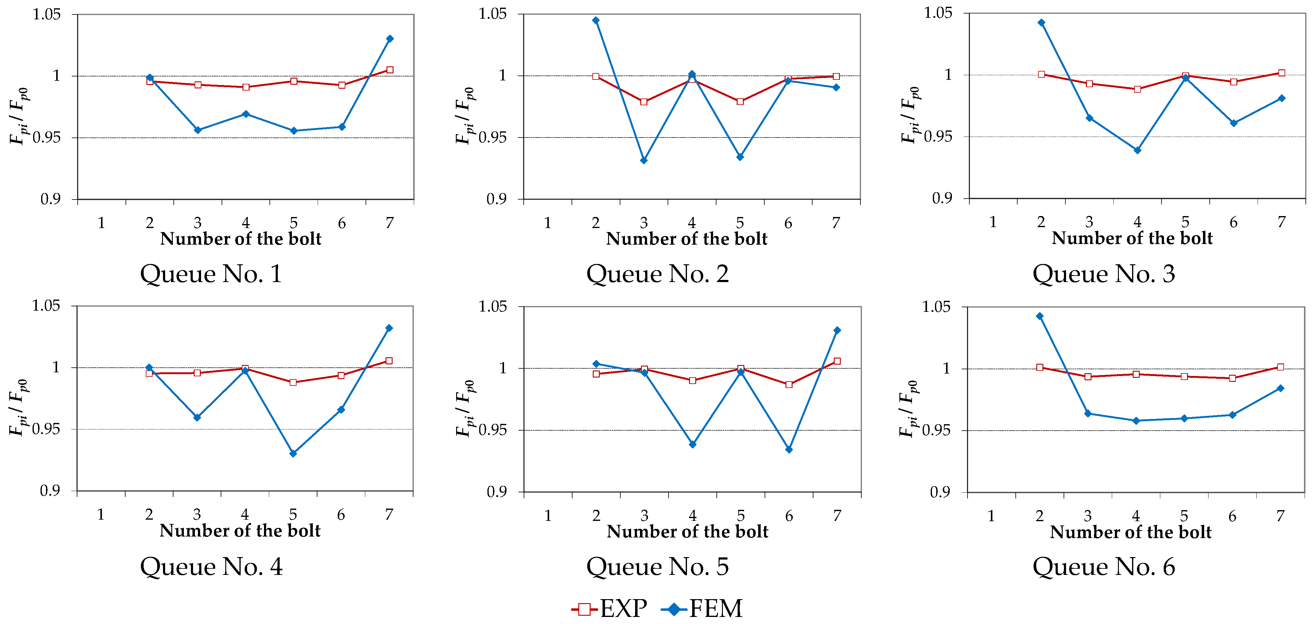
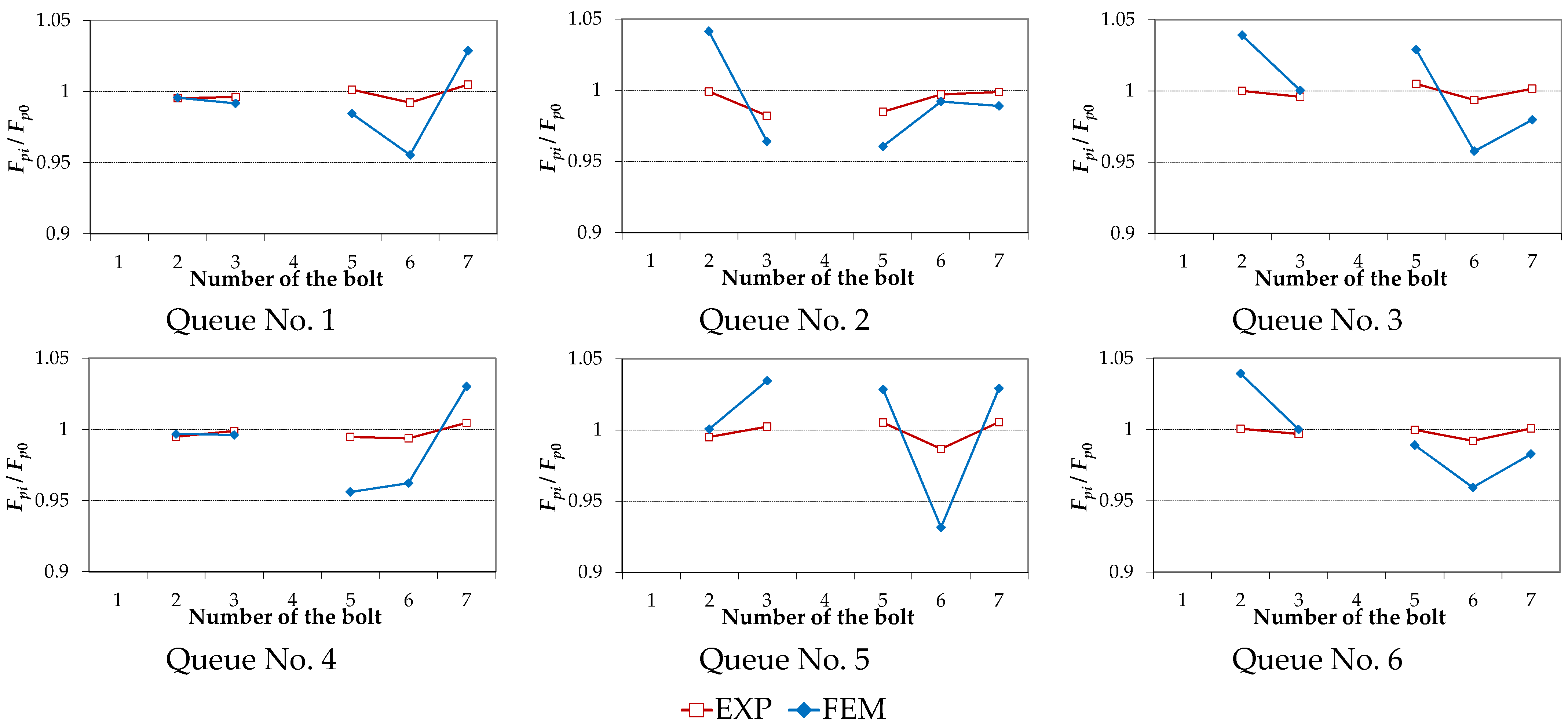
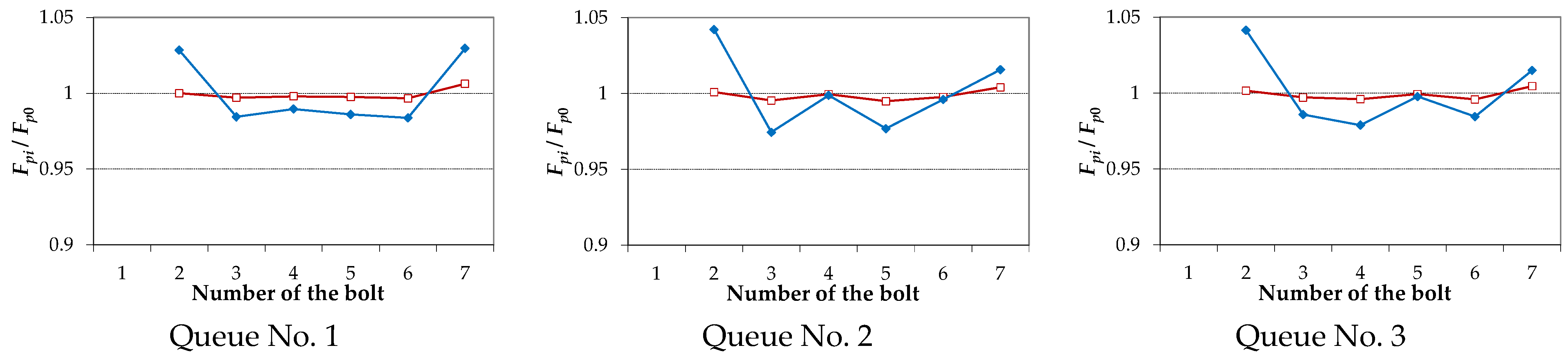
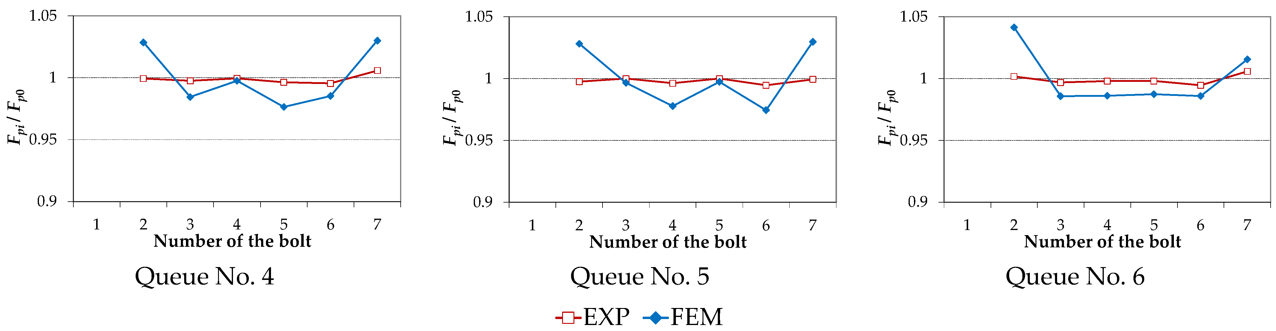
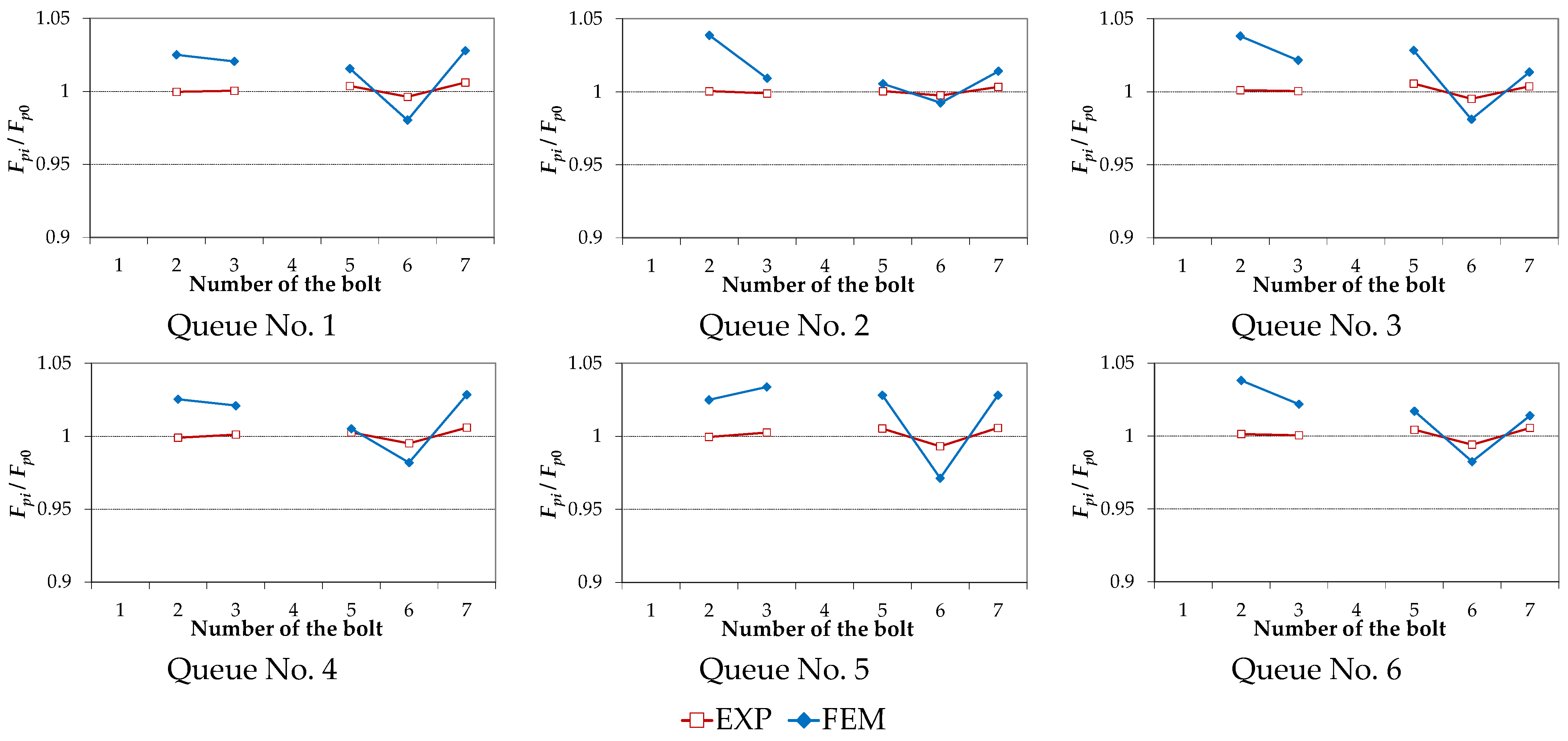
Figure 6, Figure 7, Figure 8 and Figure 9 compare the results of the calculations using the FEM-based model of the joint with the experimental results presented in [23]. The charts of the bolt forces Fpi normalised in respect to the value of the initial force Fp0 after their preloading in the single pass and at the end of State No. 1 of the joint damage are depicted in Figure 6. Figure 7 contains analogous charts for the case of State No. 2 of the joint damage. Results obtained in the same way for three-pass preloading are shown in Figure 8 and Figure 9.
- The preload charts for the respective bolts in the state of the joint damage reveal a certain variability.
- By increasing the number of passes during the multi-bolted joint preloading, it was possible to reduce the variability of values of the bolt forces in the state of the joint damage.
The quantitative analysis of the results shown in Figure 6, Figure 7, Figure 8 and Figure 9 was conducted using the Z2 indicator, defined as follows:
where is the force in the bolt No. i in the given force chart according to experimental tests, and is the force in the bolt No. i in the given force chart according to the FEM-based model.
The maximal Z2 indicator values received for respective methods of preloading and the states of the joint damage are shown in Table 5. They do not exceed 6%. To sum up the analysis of the results, it can be noted that the presented FEM-based model of the multi-bolted joint allowed determination of the bolt force values at a compelling level. Moreover, it has been proven that the use of simplified bolt models is very useful in modelling multi-bolted joints.
6. Concluding Remarks
This paper presented the method of modelling of the asymmetrical multi-bolted joint in the bolt damage state. The described study investigated the influence of the preloading process (various preloading sequences and number of passes) on the forces acting in bolts after damage occurrence. The applicability of the proposed method was validated by comparison with experimental data, which proves its usefulness in engineering practice.
The presented model can be extended using the theory of asymmetric guide waves [53] in order to create a quantitative criterion for determining whether the multi-bolted joint has entered a state of damage.
Author Contributions
Conceptualization, R.G. and M.W.; methodology, R.G.; software, R.G.; validation, R.G., M.W. and K.U.; formal analysis, R.G.; investigation, R.G.; resources, R.G.; data curation, R.G.; writing—original draft preparation, R.G.; writing—review and editing, R.G., M.W. and K.U.; visualization, R.G.; supervision, R.G.; project administration, R.G.; funding acquisition, K.U. All authors have read and agreed to the published version of the manuscript.
Funding
This research received no external funding.
Data Availability Statement
Data available upon request from the corresponding author.
Conflicts of Interest
The authors declare no conflict of interest.
References
- Nazarko, P.; Ziemianski, L. Force identification in bolts of flange connections for structural health monitoring and failure prevention. Procedia Struct. Integr. 2017, 5, 460–467. [Google Scholar] [CrossRef]
- Qin, X.; Peng, C.; Zhao, G.; Ju, Z.; Lv, S.; Jiang, M.; Sui, Q.; Jia, L. Full life-cycle monitoring and earlier warning for bolt joint loosening using modified vibro-acoustic modulation. Mech. Syst. Signal Process. 2022, 162, 108054. [Google Scholar] [CrossRef]
- Demetgul, M.; Senyurek, V.Y.; Uyandik, R.; Tansel, I.N.; Yazicioglu, O. Evaluation of the health of riveted joints with active and passive structural health monitoring techniques. Measurement 2015, 69, 42–51. [Google Scholar] [CrossRef]
- Winkler, J.; Hendy, C. Improved structural health monitoring of London’s docklands light railway bridges using digital image correlation. Struct. Eng. Int. 2017, 27, 435–440. [Google Scholar] [CrossRef]
- Tochaei, E.N.; Fang, Z.; Taylor, T.; Babanajad, S.; Ansari, F. Structural monitoring and remaining fatigue life estimation of typical welded crack details in the Manhattan Bridge. Eng. Struct. 2021, 231, 111760. [Google Scholar] [CrossRef]
- Jamrozik, W.; Górka, J.; Wyględacz, B.; Kiel-Jamrozik, M. FEM-based thermogram correction for Inconel 625 joint hardness clustering. Materials 2022, 15, 1113. [Google Scholar] [CrossRef]
- Kudu, F.N.; Bayraktar, A.; Bakir, P.G.; Türker, T.; Altunişik, A.C. Ambient vibration testing of Berta Highway Bridge with post-tension tendons. Steel Compos. Struct. 2014, 16, 23–46. [Google Scholar] [CrossRef]
- Yan, G.; Dyke, S.J.; Irfanoglu, A. Experimental validation of a damage detection approach on a full-scale highway sign support truss. Mech. Syst. Signal Process. 2012, 28, 195–211. [Google Scholar] [CrossRef]
- Pérez, M.A.; Font-Moré, J.; Fernández-Esmerats, J. Structural damage assessment in lattice towers based on a novel frequency domain-based correlation approach. Eng. Struct. 2021, 226, 111329. [Google Scholar] [CrossRef]
- Pham, C.H.; Hancock, G.J. Tension field action for cold-formed sections in shear. J. Constr. Steel Res. 2012, 72, 168–178. [Google Scholar] [CrossRef]
- Pham, C.H.; Zelenkin, D.; Hancock, G.J. Effect of flange restraints on shear tension field action in cold-formed C-sections. J. Constr. Steel Res. 2017, 129, 42–53. [Google Scholar] [CrossRef]
- Martowicz, A.; Sendecki, A.; Salomon, M.; Rosiek, M.; Uhl, T. Application of electromechanical impedance-based SHM for damage detection in bolted pipeline connection. Nondestruct. Test. Eval. 2016, 31, 17–44. [Google Scholar] [CrossRef]
- Thien, A.B.; Chiamori, H.C.; Ching, J.T.; Wait, J.R.; Park, G. The use of macro-fibre composites for pipeline structural health assessment. Struct. Control Health Monit. 2008, 15, 43–63. [Google Scholar] [CrossRef]
- Blachowski, B.; Swiercz, A.; Gutkiewicz, P.; Szelążek, J.; Gutkowski, W. Structural damage detectability using modal and ultrasonic approaches. Measurement 2016, 85, 210–221. [Google Scholar] [CrossRef]
- Li, J.; Hao, H. Health monitoring of joint conditions in steel truss bridges with relative displacement sensors. Measurement 2016, 88, 360–371. [Google Scholar] [CrossRef] [Green Version]
- Beskhyroun, S.; Oshima, T.; Mikami, S. Wavelet-based technique for structural damage detection. Struct. Control Health Monit. 2010, 17, 473–494. [Google Scholar] [CrossRef]
- Beskhyroun, S.; Oshima, T.; Mikami, S.; Miyamori, Y. Assessment of vibration-based damage identification techniques using localized excitation source. J. Civ. Struct. Health Monit. 2013, 3, 207–223. [Google Scholar] [CrossRef]
- Kromanis, R.; Kripakaran, P. SHM of bridges: Characterising thermal response and detecting anomaly events using a temperature-based measurement interpretation approach. J. Civ. Struct. Health Monit. 2016, 6, 237–254. [Google Scholar] [CrossRef] [Green Version]
- Kromanis, R.; Kripakaran, P. Data-driven approaches for measurement interpretation: Analysing integrated thermal and vehicular response in bridge structural health monitoring. Adv. Eng. Inform. 2017, 34, 46–59. [Google Scholar] [CrossRef] [Green Version]
- Kunwar, A.; Jha, R.; Whelan, M.; Janoyan, K. Damage detection in an experimental bridge model using Hilbert-Huang transform of transient vibrations. Struct. Control Health Monit. 2013, 20, 1–15. [Google Scholar] [CrossRef]
- Whelan, M.J.; Gangone, M.V. Effect of measurement uncertainties on strain-based damage diagnostics for highway bridges. J. Civ. Struct. Health Monit. 2015, 5, 321–335. [Google Scholar] [CrossRef]
- Becht, P.; Deckers, E.; Claeys, C.; Pluymers, B.; Desmet, W. Loose bolt detection in a complex assembly using a vibro-acoustic sensor array. Mech. Syst. Signal Process. 2019, 130, 433–451. [Google Scholar] [CrossRef]
- Grzejda, R.; Parus, A. Health assessment of a multi-bolted connection due to removing selected bolts. FME Trans. 2021, 49, 634–642. [Google Scholar] [CrossRef]
- Rucka, M.; Zima, B.; Kędra, R. Application of guided wave propagation in diagnostics of steel bridge components. Arch. Civ. Eng. 2014, 60, 493–515. [Google Scholar] [CrossRef] [Green Version]
- Qin, Z.; Han, Q.; Chu, F. Bolt loosening at rotating joint interface and its influence on rotor dynamics. Eng. Fail. Anal. 2016, 59, 456–466. [Google Scholar] [CrossRef]
- Blachowski, B.; Gutkowski, W. Effect of damaged circular flange-bolted connections on behaviour of tall towers, modelled by multilevel substructuring. Eng. Struct. 2016, 111, 93–103. [Google Scholar] [CrossRef]
- Patil, C.S.; Roy, S.; Jagtap, K.R. Damage detection in frame structure using piezoelectric actuator. Mater. Today Proc. 2017, 4, 687–692. [Google Scholar] [CrossRef]
- Hasni, H.; Jiao, P.; Alavi, A.H.; Lajnef, N.; Masri, S.F. Structural health monitoring of steel frames using a network of self-powered strain and acceleration sensors: A numerical study. Autom. Constr. 2018, 85, 344–357. [Google Scholar] [CrossRef]
- Grzejda, R.; Parus, A. Experimental studies of the process of tightening an asymmetric multi-bolted connection. IEEE Access 2021, 9, 47372–47379. [Google Scholar] [CrossRef]
- Grzejda, R.; Parus, A.; Kwiatkowski, K. Experimental studies of an asymmetric multi-bolted connection under monotonic loads. Materials 2021, 14, 2353. [Google Scholar] [CrossRef]
- Baranowski, P.; Damaziak, K.; Małachowski, J. Brake system studies using numerical methods. Eksploat. Niezawodn. Maint. Reliab. 2013, 15, 337–342. [Google Scholar]
- Woch, M. Reliability analysis of the PZL-130 Orlik TC-II aircraft structural component under real operating conditions. Eksploat. Niezawodn. Maint. Reliab. 2017, 19, 287–295. [Google Scholar] [CrossRef]
- Wysmulski, P. The analysis of buckling and post buckling in the compressed composite columns. Arch. Mater. Sci. Eng. 2017, 85, 35–41. [Google Scholar] [CrossRef]
- Croccolo, D.; De Agostinis, M.; Vincenzi, N. A contribution to the selection and calculation of screws in high duty bolted joints. Int. J. Press. Vessels Pip. 2012, 96–97, 38–48. [Google Scholar] [CrossRef]
- Croccolo, D.; De Agostinis, M.; Vincenzi, N. Influence of tightening procedures and lubrication conditions on titanium screw joints for lightweight applications. Tribol. Int. 2012, 55, 68–76. [Google Scholar] [CrossRef]
- Croccolo, D.; De Agostinis, M.; Fini, S.; Olmi, G.; Robusto, F.; Vincenzi, N. Steel screws on aluminium nuts: Different engagement ratio tapped threads compared to threaded inserts with a proper tolerance choice. Tribol. Int. 2019, 138, 297–306. [Google Scholar] [CrossRef]
- Majda, P.; Jastrzębska, J. Measurement uncertainty of generalized stiffness of machine tools. Measurement 2021, 170, 108692. [Google Scholar] [CrossRef]
- Wang, G.; Ding, Y. The interface friction in the friction-type bolted joint of steel truss bridge: Case study. Balt. J. Road Bridge Eng. 2020, 15, 187–210. [Google Scholar] [CrossRef]
- Daniūnas, A.; Urbonas, K. Influence of the semi-rigid bolted steel joints on the frame behaviour. J. Civ. Eng. Manag. 2010, 16, 237–241. [Google Scholar] [CrossRef] [Green Version]
- PN-EN 1993-1-8, 2006; Eurocode 3: Design of Steel Structures, Part 1–8: Design of Joints. Polish Committee for Standardization: Warsaw, Poland, 2006.
- Palenica, P.; Powałka, B.; Grzejda, R. Assessment of modal parameters of a building structure model. Springer Proc. Math. Stat. 2016, 181, 319–325. [Google Scholar] [CrossRef]
- Grzejda, R. Modelling nonlinear multi-bolted systems on the assembly state. Procedia Eng. 2017, 206, 1808–1812. [Google Scholar] [CrossRef]
- Stosiak, M. The modelling of hydraulic distributor slide–sleeve interaction. Arch. Civ. Mech. Eng. 2012, 12, 192–197. [Google Scholar] [CrossRef]
- Zmarzły, P. Influence of bearing raceway surface topography on the level of generated vibration as an example of operational heredity. Indian J. Eng. Mater. Sci. 2020, 27, 356–364. [Google Scholar]
- Zmarzły, P. Technological heredity of the turning process. Tech. Gaz. 2020, 27, 1194–1203. [Google Scholar] [CrossRef]
- Jaszak, P. The elastic serrated gasket of the flange bolted joints. Int. J. Press. Vessels Pip. 2019, 176, 103954. [Google Scholar] [CrossRef]
- Jamia, N.; Jalali, H.; Taghipour, J.; Friswell, M.I.; Khodaparast, H.H. An equivalent model of a nonlinear bolted flange joint. Mech. Syst. Signal Process. 2021, 153, 107507. [Google Scholar] [CrossRef]
- Yang, B.; Sun, Q.; Lin, Q.; Wang, L.; Zhang, X.; Ma, Y. Influence mechanism of bolted joint with geometric irregularity bearing surface on anti-loosening performance. Int. J. Press. Vessels Pip. 2021, 191, 104364. [Google Scholar] [CrossRef]
- Grzejda, R. Impact of nonlinearity of the contact layer between elements joined in a multi-bolted system on its preload. Int. J. Appl. Mech. Eng. 2017, 22, 921–930. [Google Scholar] [CrossRef] [Green Version]
- Grzesik, W. Effect of the machine parts surface topography features on the machine service. Mechanik 2015, 88, 587–593. (In Polish) [Google Scholar] [CrossRef] [Green Version]
- Łukaszewicz, A. Temperature field in the contact zone in the course of rotary friction welding of metals. Mater. Sci. 2019, 55, 39–45. [Google Scholar] [CrossRef]
- Borawski, A.; Szpica, D.; Mieczkowski, G. Verification tests of frictional heat modelling results. Mechanika 2020, 26, 260–264. [Google Scholar] [CrossRef]
- Soleimanpour, R.; Soleimani, S.M.; Mohammad, N.K. Damage detection and localization in loose bolted joints. Procedia Struct. Integr. 2022, 37, 956–963. [Google Scholar] [CrossRef]
Figure 1.
Physical model of the connection (a) and physical model of the single fastener (b).

Figure 2.
Outline of the surface at the contact of the joined plates and assumed numbering of the bolts.
Figure 2.
Outline of the surface at the contact of the joined plates and assumed numbering of the bolts.

Figure 3.
FEM-based model of the multi-bolted joint (a) and FEM-based model of the single fastener (b).
Figure 3.
FEM-based model of the multi-bolted joint (a) and FEM-based model of the single fastener (b).

Figure 4.
Bolt forces for single-pass tensioning of the joint.

Figure 5.
Bolt forces for multi-pass tensioning of the joint.


Figure 6.
Bolt forces in State No. 1 for single-pass joint preload.

Figure 7.
Bolt forces in State No. 2 for single-pass joint preload.

Figure 8.
Bolt forces in State No. 1 for multi-pass joint preload.


Figure 9.
Bolt forces in State No. 2 for multi-pass joint preload.


Table 1.
Methods of assembling the joint.
| Designation | Meaning | Level |
|---|---|---|
| Single-pass preloading | ||
| Fpi | Preloading of the i-th bolt | Fpi = 22 kN |
| Multi-pass preloading | ||
| Fpi1 | Preload of the i-th bolt in pass No. 1 | 0.2 Fpi = 4.4 kN |
| Fpi2 | Preload of the i-th bolt in pass No. 2 | 0.6 Fpi = 13.2 kN |
| Fpi3 | Preload of the i-th bolt in pass No. 3 | Fpi = 22 kN |
Table 2.
Orders of bolt preloading.
| Queue No. | Order of Bolts | Queue No. | Order of Bolts |
|---|---|---|---|
| 1 | 1-2-3-4-5-6-7 | 4 | 1-5-2-6-3-7-4 |
| 2 | 1-3-5-7-2-4-6 | 5 | 1-6-4-2-7-5-3 |
| 3 | 1-4-7-3-6-2-5 | 6 | 1-7-6-5-4-3-2 |
Table 3.
Joint damage states.
| 1 | 2 |
|---|---|
 |  |
Table 4.
Percentage values of the Z1 indicator.
| Queue No. | Single-Pass Preloading | Multi-Pass Preloading | ||
|---|---|---|---|---|
| State No. 1 | State No. 2 | State No. 1 | State No. 2 | |
| 1 | 4.04 | 3.37 | 4.04 | 3.32 |
| 2 | 4.28 | 3.17 | 4.16 | 3.23 |
| 3 | 4.28 | 3.31 | 4.16 | 3.28 |
| 4 | 4.03 | 3.47 | 4.03 | 3.35 |
| 5 | 4.10 | 3.47 | 4.05 | 3.37 |
| 6 | 4.28 | 3.41 | 4.16 | 3.31 |
Table 5.
Percentage values of the Z2 indicator.
| Queue No. | Single-Pass Preloading | Multi-Pass Preloading | ||
|---|---|---|---|---|
| State No. 1 | State No. 2 | State No. 1 | State No. 2 | |
| 1 | 4.05 | 3.71 | 2.84 | 2.54 |
| 2 | 4.85 | 4.23 | 4.13 | 3.82 |
| 3 | 5.01 | 3.91 | 3.99 | 3.69 |
| 4 | 5.84 | 3.88 | 2.92 | 2.63 |
| 5 | 5.32 | 5.60 | 3.07 | 3.11 |
| 6 | 4.15 | 3.86 | 3.97 | 3.67 |
Publisher’s Note: MDPI stays neutral with regard to jurisdictional claims in published maps and institutional affiliations. |
© 2022 by the authors. Licensee MDPI, Basel, Switzerland. This article is an open access article distributed under the terms and conditions of the Creative Commons Attribution (CC BY) license (https://creativecommons.org/licenses/by/4.0/).
Share and Cite
MDPI and ACS Style
Grzejda, R.; Warzecha, M.; Urbanowicz, K. Determination of the Preload of Bolts for Structural Health Monitoring of a Multi-Bolted Joint: FEM Approach. Lubricants 2022, 10, 75. https://0-doi-org.brum.beds.ac.uk/10.3390/lubricants10050075
AMA Style
Grzejda R, Warzecha M, Urbanowicz K. Determination of the Preload of Bolts for Structural Health Monitoring of a Multi-Bolted Joint: FEM Approach. Lubricants. 2022; 10(5):75. https://0-doi-org.brum.beds.ac.uk/10.3390/lubricants10050075
Chicago/Turabian StyleGrzejda, Rafał, Mariusz Warzecha, and Kamil Urbanowicz. 2022. "Determination of the Preload of Bolts for Structural Health Monitoring of a Multi-Bolted Joint: FEM Approach" Lubricants 10, no. 5: 75. https://0-doi-org.brum.beds.ac.uk/10.3390/lubricants10050075
Note that from the first issue of 2016, this journal uses article numbers instead of page numbers. See further details here.