Assessment of the Tribological Properties of the Steel/Polymer/Steel Sandwich Material LITECOR


1
Department of Manufacturing and Production Engineering, Rzeszow University of Technology, al. Powst. Warszawy 8, 35-959 Rzeszów, Poland
2
Institute of Technology and Material Engineering, Faculty of Mechanical Engineering, Technical University of Košice, Mäsiarska 74, 040 01 Košice, Slovakia
*
Author to whom correspondence should be addressed.
Lubricants 2022, 10(5), 99; https://0-doi-org.brum.beds.ac.uk/10.3390/lubricants10050099
Submission received: 1 April 2022
/
Revised: 26 April 2022
/
Accepted: 9 May 2022
/
Published: 14 May 2022
(This article belongs to the Special Issue Design for Tribology: Theoretical and Practical Assessment in Modern Mechanical Components)
Abstract
:The article presents the results of tribological investigations into the steel/polymer/steel sandwich material LITECOR® developed by ThyssenKrupp Steel Europe for applications in the automotive industry. Friction tests were carried out by means of a strip drawing test with the use of a special tribotester mounted on a uniaxial tensile test machine. The influence of sheet deformation on the value of the coefficient of friction (COF) was considered. For this purpose, the samples were subjected to a pre-deformation of 4%, 8% and 12%. Friction tests were carried out with different force values and under different friction conditions, i.e., in dry friction conditions and lubrication of the sheet surface with L-AN 46 machine oil. The highest values of COF were observed for as-received sheets. In contrast, apart from the friction process under the conditions of the lowest force analysed, the lowest value of the COF was observed for pre-strained sheets with a deformation of 12%. The lubrication efficiency of the pre-strained strip specimens with ε = 4% was between 10.5% and 16.3%, with a trend of increasing lubrication efficiency with increasing force. For pre-strained sheets with deformation ε = 12%, there was a trend of decreasing effectiveness from 14.9% to 9.03% with an increase in force.
1. Introduction
Steel and non-ferrous metal alloys are commonly used to produce multilayer structures consisting of adhesively bonded metallic layers. Reinforced composites are classified into four groups: particulate-filled polymer composites, diffusion composites, layered composites, and composites reinforced with a thermoplastic or thermosetting polymer matrix [1]. Composites are materials with a heterogeneous structure composed of two or more materials with different properties. Most frequently, one of the components is the matrix, which provides the structure with adequate flexibility and cohesion [2]. Due to a large number of varieties of composite structures, it is difficult to clearly define the concept of a composite. Aluminium alloy sandwich materials can be produced with a polymer core in a homogeneous or structured form and are often bonded together using epoxy resins [3,4].
Aluminium alloys are the basic material for the production of Fibre Metal Laminates (FMLs) for the aviation industry: glass-reinforced aluminium laminates (GLARE), aramid-reinforced aluminium laminate (ARALL), carbon-reinforced aluminium laminate (CARALL), kenaf fibre-reinforced aluminium alloy (CAKRALL) and flax fibre-reinforced aluminium alloy (CAFRALL) [5]. In addition to the above-mentioned groups of laminates, aluminium alloys are used in various configurations to produce other layered composites based on, e.g., EN AW-2024 [6], EN AW-5083 [7], EN AW-6082 [8], EN AW-7075 [9], EN AW-8090 [10] and many other aluminium alloys [5].
The stimulator of the development of new lightweight, high-strength materials for the automotive and aircraft industries is the continued drive to reduce fuel consumption without compromising vehicle performance. FMLs were originally developed for structural applications in aviation, and taking into account their low-density show very good fatigue properties, increased resistance to impact, fire resistance and ease of manufacture and repair [6,11]. Examples of three-layer Al/polymer/Al FMLs are the HYLITE [12] and DIBOND [13] composites developed by the Corus Group. Hylite is an aluminium/polypropylene/aluminium structure with a thickness of 0.2/0.8/0.2 mm, which was used for the first time in the Audi A2 [14,15]. The DIBOND composite is composed of two layers of aluminium sheets with a thickness of 0.3, between which there is a polyethylene core [16]. Hylite can be shaped by conventional forming methods such as drawing [17].
In addition to the commonly known sandwich composites based on aluminium alloy sheets, interest has increased in hybrid structures consisting of a combination of steel sheets and a polypropylene core. Steel-polymer laminates (steel/polymer/steel) show high fatigue strength and impact strength [18,19]. Examples are Bondal and Litecor sandwich materials. BONDAL laminate with a configuration of 0.5/0.5/0.5 mm is used for damping applications [20]. LITECOR® laminate consists of two layers of HX220YD interstitial steel sheets (0.2–0.5 mm) with a polyamide (PA)/polyethylene (PE) intermediate layer (52 wt.% PA6, 36 wt.% PE and 12 wt.% other additives) [21]. The significant advantages of this class of materials are their improved acoustic and thermal damping properties. Hybrix, a laminate developed by Lamera AB, consists of steel or polyamide microfibres sandwiched between two metallic sheets (stainless steel, carbon steel or aluminium). This material is produced with a thickness of 0.5–3.5 mm with a total weight between 1.0 and 8.5 kg/m² (depending on the configuration) [22].
Steel/polymer/steel composites can be deep drawn and bent [23,24]. Plastic working of composite materials requires knowledge of the changing tribological properties of plates during the forming process. It is especially important in the deep drawing process where different friction conditions and different normal pressures occur in various areas of the sheet metal thus formed. Mosse et al. [25] examined the effect of different friction coefficients, which could be the result of different temperatures, in forming aluminium/polypropylene/aluminium panels. Murtagh et al. [26] conducted shear tests on carbon-fibre-reinforced poly (ether ether ketone) and glass fibre-reinforced PA-12 against steel. The strip drawing test was used. They found that the shear stresses generated were greatly affected by the temperature and normal force. Rajabi and Kadkhodayan [27] tested the behaviour of an FML consisting of glass-fibre reinforced polypropylene laminate as the core and AA1200-O aluminium alloy sheet as the skin layers in the deep drawing process. The friction coefficients of the top plates in the range 0.18–0.23 were determined in a strip drawing test for different blank holder forces corresponding to the real forming conditions. Wollmann et al. [28] analysed the behaviour of a sandwich laminate consisting of a carbon fibre-reinforced thermoplastic core and HC220Y steel cover sheets experimentally, analytically and numerically during deep drawing of a cylindrical draw piece. The value of the coefficient was arbitrarily determined as 0.2. Sexton et al. [29] investigated the effects of the material model on FML formability using finite element analysis. The effects of friction between the die and workpiece and the blank holder and workpiece were studied separately. The effect of friction between the workpiece and the tools in the FEM model was shown to have a significant effect on the results. Deep drawing of a unidirectional carbon-fibre-reinforced Polyamide 6 core (middle layer) bonded to metal cover layers both made of HC340 LA steel alloy has been carried out by Hahn et al. [30]. The authors investigated the effect of changes in the coefficient of friction between 0.1 and 0.3 on blank holder intensity during the forming of a non-symmetrical draw piece. Dharmalingam et al. [31] used the statistical experiments and finite element method to determine the influence of the parameters of the forming process of 2/1-aluminium/composite consisting of two layers of comingled 2:2 twill weave glass-fibre/polypropylene composite prepreg and annealed EN AW-5005-H34 aluminium sheets. The coefficient of friction between the FML blank and the forming tools was arbitrarily assumed to be constant with a value of 0.031. The value of the coefficient of friction was not justified. Ten Thije et al. [32] experimentally studied the coefficient of friction of the tool-ply frictional behaviour of thermoplastic laminates using a strip drawing test. The results yielded friction coefficients between 0.05 and 0.47, depending on the testing conditions.
Friction is an important phenomenon that can dominate the resulting product geometry of FMLs upon plastic forming. Analysis of the literature shows that there is a lack of comprehensive results of friction testing, especially in steel/polymer/steel laminates. So far, no friction test results have been found for the relatively new steel/polymer/steel type sandwich material LITECOR®, which has been developed by ThyssenKrupp Steel Europe as a response by the automotive industry to the demand for lightweight load-bearing structures with increased stiffness. Therefore, in this paper, the LITECOR® sheets have been tested in a strip drawing test under the various normal loads corresponding to real forming conditions. Moreover, studies were carried out on the effect of FML deformation, which changes the topography of the FML surface, on the friction properties.
2. Materials and Methods
2.1. Material
The 1.3-mm-thick steel/polymer/steel sandwich material LITECOR® developed by ThyssenKrupp Steel Europe was used as test material. LITECOR® is a three-layer metal-based laminate consisting of a 0.7 mm thick polymer core and HX220YD + Z75 steel sheets with a thickness of 0.3 mm as outer layers. LITECOR® was produced by the hot adhesive bonding process. The external steel layers were protected against corrosion with a zinc coating ZE75, which equates to a zinc layer of 7.5 microns on both sides [33]. Selected mechanical properties of the zinc coating are shown in Table 1. ThyssenKrupp has identified at least 14 potential LITECOR® applications for high–stiffness and large flat bodywork components such as hoods, tailgates, doors and roofs. Structural elements coated with a zinc layer are mainly exposed to atmospheric corrosion. Jonnson [34] tested the corrosion of zinc in the automotive environment in several regions of the world, varying in relative humidity and temperature. It was concluded that the most corrosive automotive environment was found in cold, humid regions. It was also found that regions with a cold, humid climate (using de-icing salts) yield a higher corrosion rate than a marine environment. Common corrosion products are hydrozincite, gordaite, simonkolleite and chlorosulphate.
The polymeric internal layer consists of 36% by weight of polyethylene, 52% by weight of polyamide 6 (PA6) and 12% by weight of other additives [35,36]. The chemical composition and selected mechanical properties of the HX220YD steel according to the EN 10346 standard [37] are listed in Table 2 and Table 3, respectively.
2.2. Friction Testing
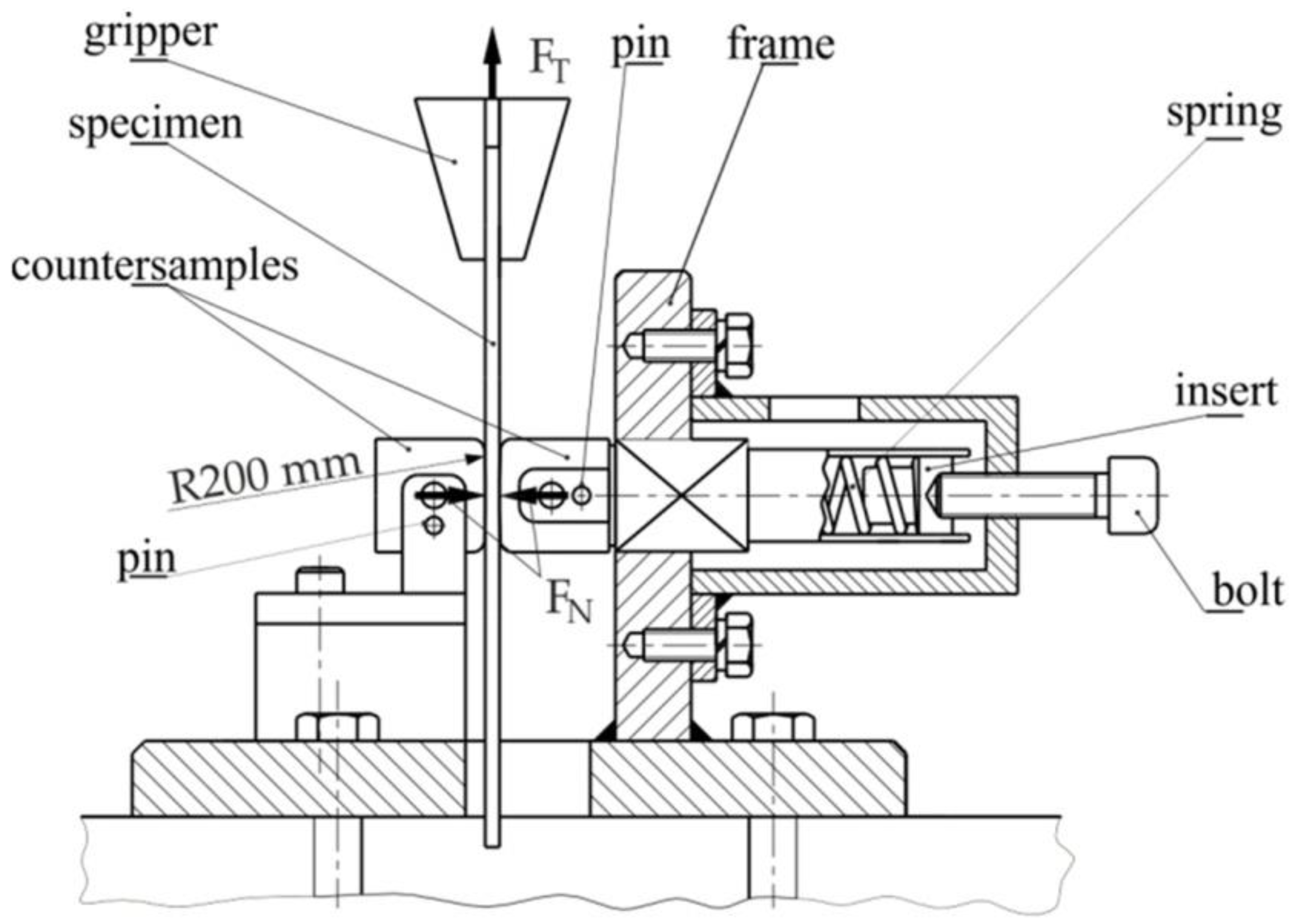
The friction tests were carried out by means of a strip drawing test with the use of a special tribotester mounted on a uniaxial tensile test machine. The tribotester (Figure 1) consists of a frame in which are mounted two counter samples with a radius of R200. The counter samples were made of cold work steel to ensure the friction conditions found in real sheet metal forming (SMF) processes are replicated. The left counter sample is fixed to the instrument frame. The right counter sample slides along a horizontal guide integrated with the tester frame. The tester frame is mounted in the lower holder of a Zwick/Roell Z100 uniaxial tensile testing machine.
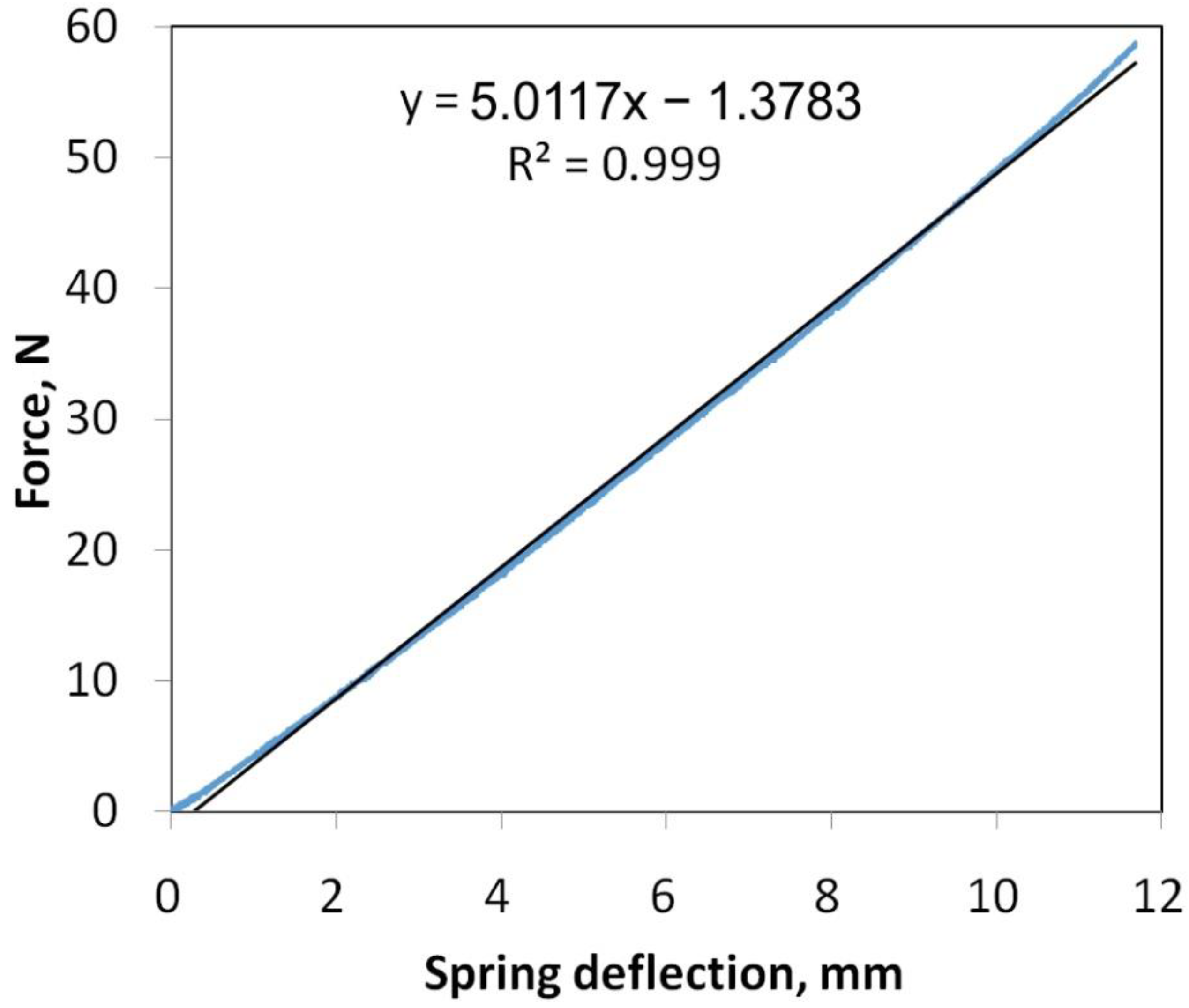
During the tests, a strip of sheet metal approximately 300 mm long and 10 mm wide is placed between the counter-samples. The upper end of the sheet strip was fixed to the upper handle of the testing machine. The force was exerted on the right counter sample by a spring with known force-displacement characteristics (Figure 2). The spring was calibrated on a MultiTest 10-i versatile tensile and compression tester. The spring characteristic was determined to be in the range of deflection between 0 and 11.5 mm, which corresponds to a force of up to 10 N.
The value of the clamping force was changed during the friction test in the range between FN = 13.65 N and FN = 51.24 N. The range of variation of the clamping force corresponds to the range of nominal pressure between 15 and 30 MPa, which fits perfectly into the range of pressures occurring in SMF [38]. Six levels of clamping force were used in this range of variation of clamping force. The upper end of the sheet strip was fixed in the upper handle of the Zwick/Roell Z100 uniaxial tensile testing machine. The tangential (friction) force FT was recorded using the measuring system of the Zwick/Roell Z100 machine. Based on the knowledge of the normal force FN, the value of the friction coefficient was determined according to the relationship:
About 200 discrete values of friction coefficient were obtained for each of the changing levels of the value of the clamping force. On their basis, the average value of the coefficient of friction μav was determined for each level of clamping force.
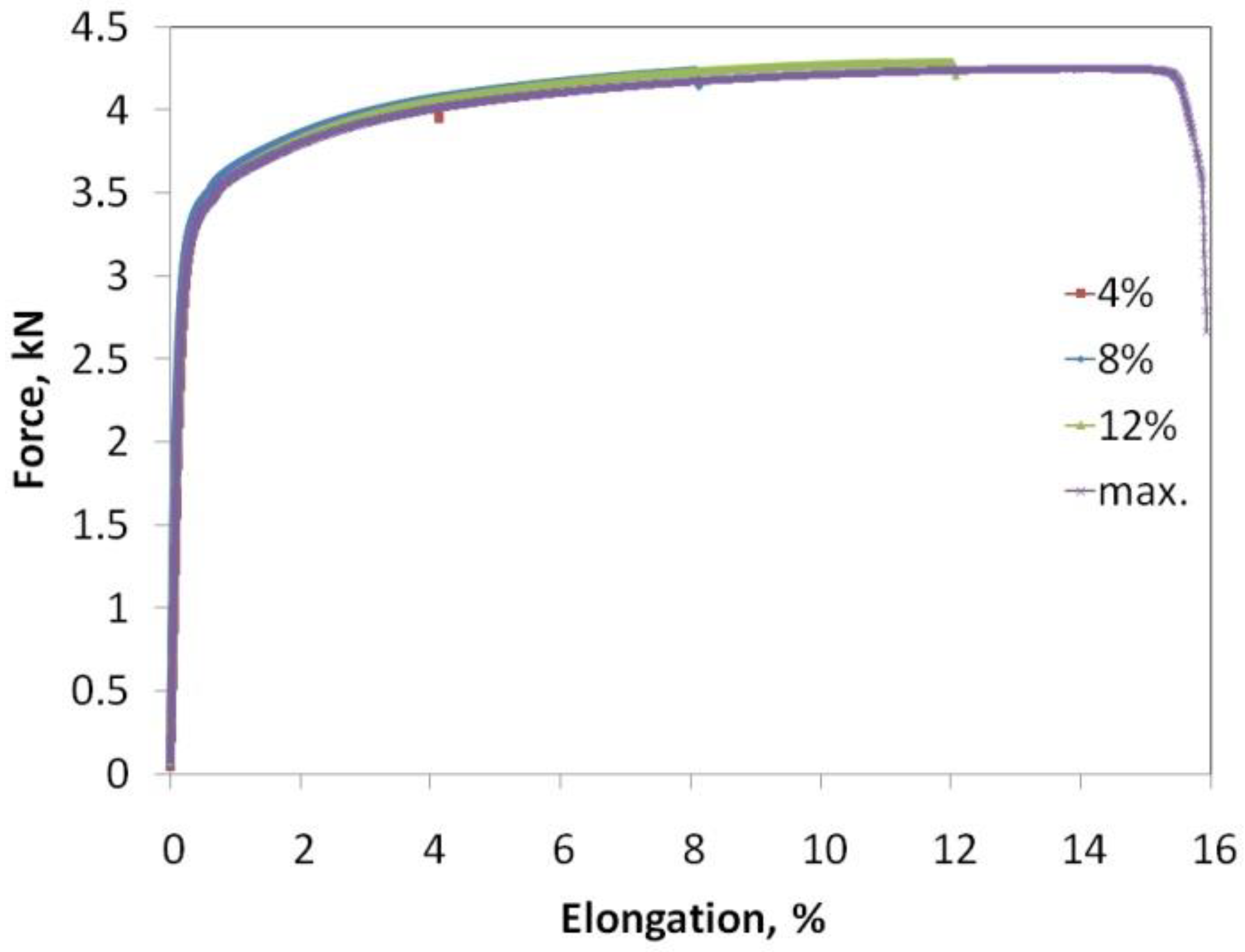
The friction tests were carried out in conditions of dry friction and lubricated conditions using L-AN 46 machine oil fabricated by the “Orlen Oil” company. The basic physical properties of the machine oil used are as follows: flow temperature −10 °C, viscosity index 94, kinematic viscosity 43.9 mm2/s. Before the friction process, the surfaces of the specimens and counter samples were cleaned with acetone. The tests were carried out on samples in the as-received state and on pre-strained samples. As a result of the pre-straining process, the topography of the sheet surface and its mechanical properties change as a result of the work hardening phenomenon. The samples were pre-strained to a strain of 4%, 8% and 12%. The tensile curves of the samples are shown in Figure 3.
The surface topographies of pre-strained surfaces before and after friction tests and the original surface roughness were examined using an PhenomProX scanning electron microscope from Nanoscience Instruments, Inc. (Phoenix, AZ, USA). The surface roughness measurements were carried out according to EN ISO 4287 standard using a Surtronic 25 (Taylor Hobson) stylus profilometer. The skewness Rsk and the kurtosis Rku were measured transverse to the direction of the specimen drawing. The surface roughness parameters were analysed with triple repetition.
3. Results and Discussion
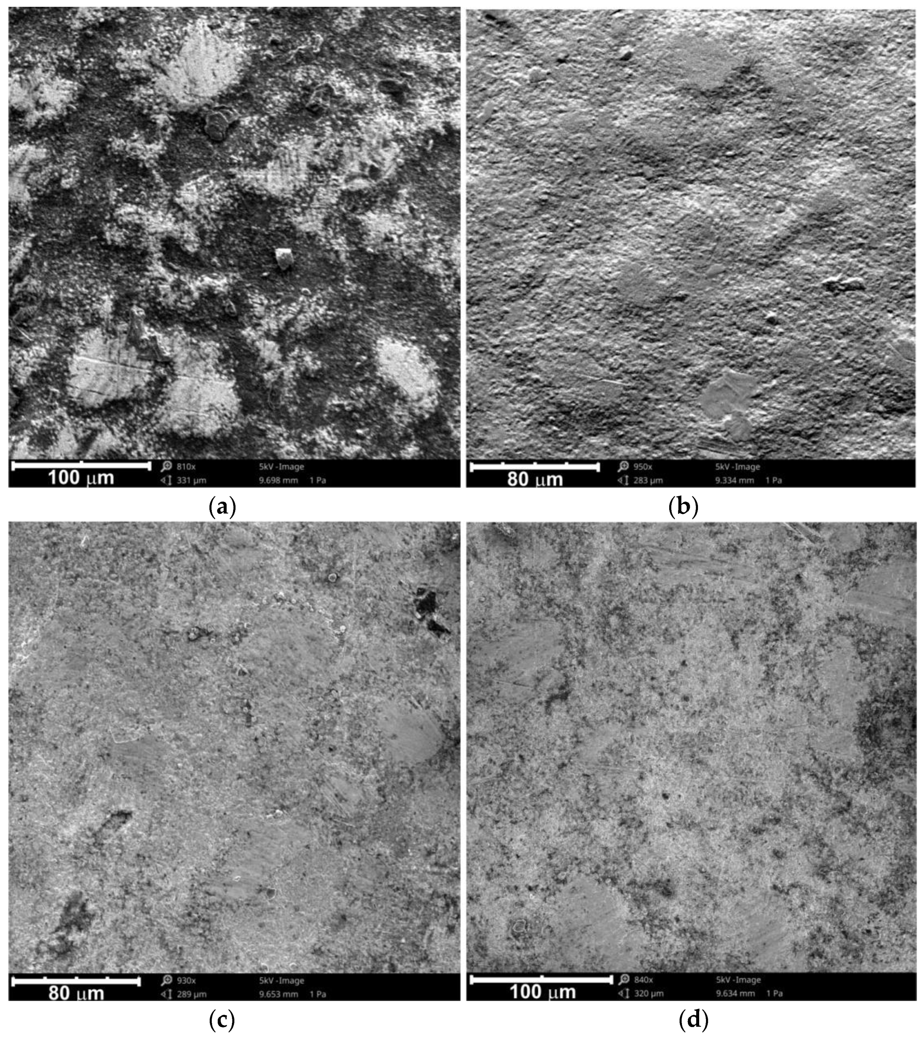
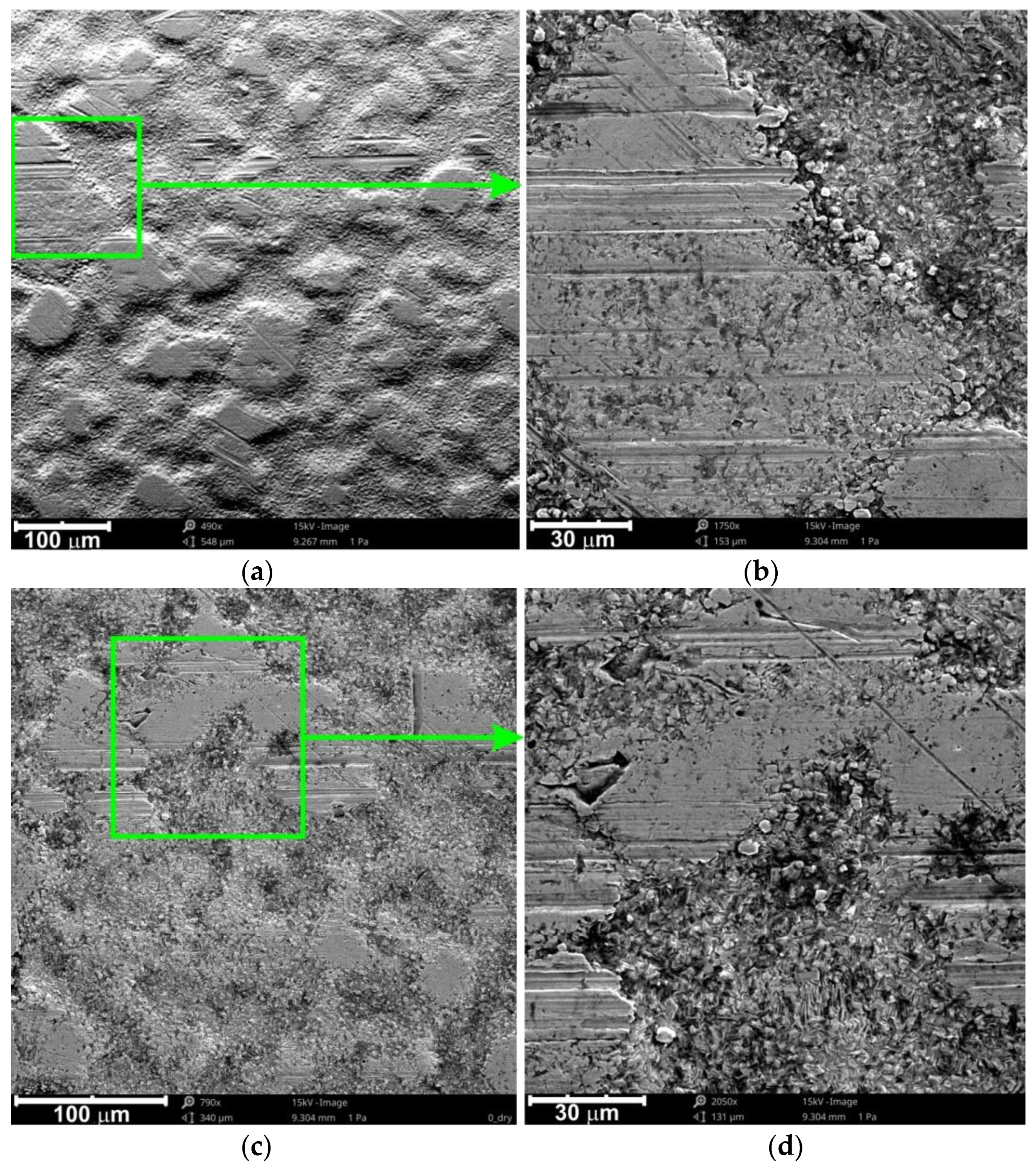
The test sheets were covered with an anti-corrosive zinc layer with high roughness and surface non-uniformity in the form of randomly oriented hills (Figure 4a). Pre-straining of the samples removed the dark rolling scale formed in the sheet production phase and increased the homogeneity of the surface. Due to the high plasticity of the zinc coating, no cracks were found in the surface layer of the pre-strained samples (Figure 4b–d).
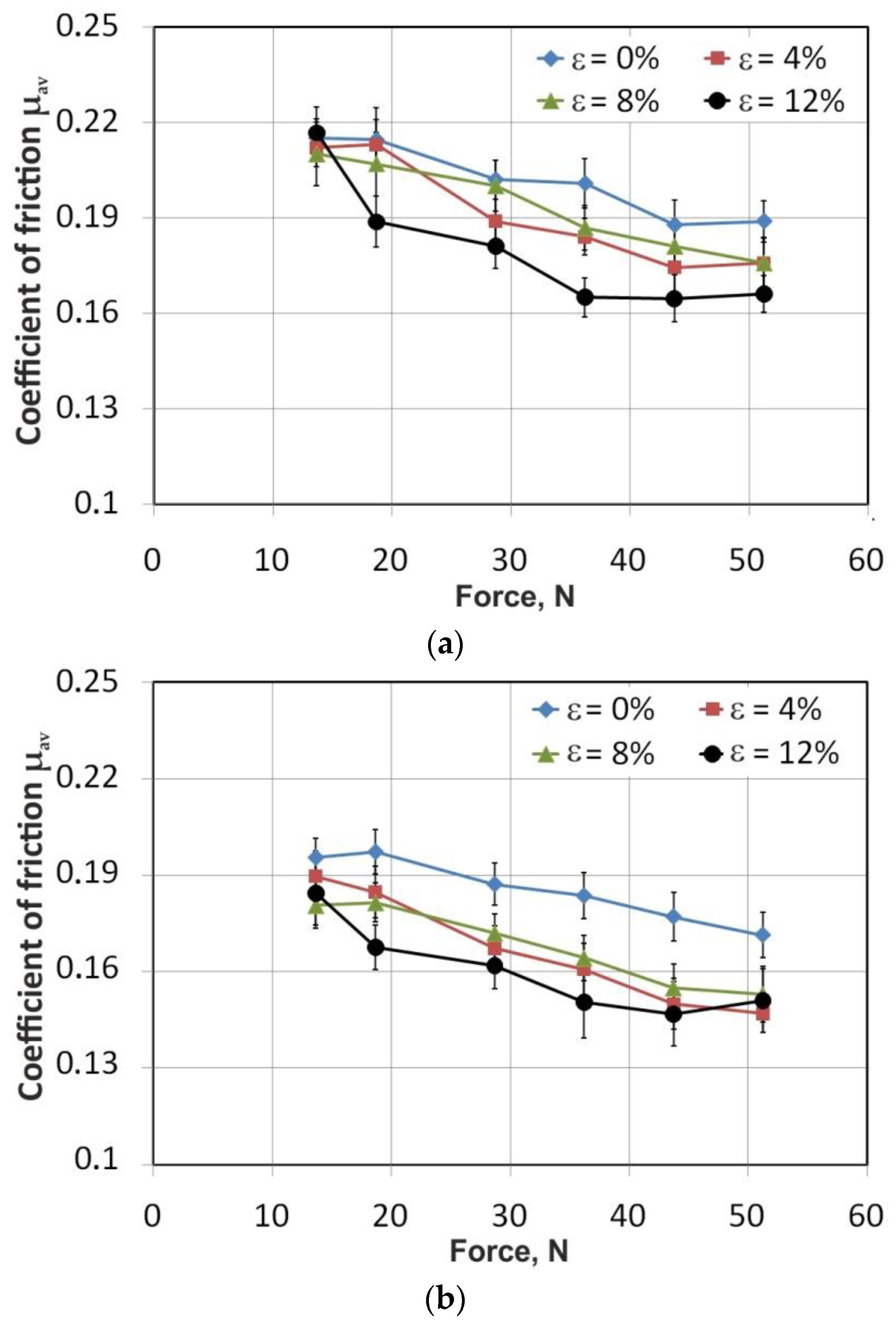
Figure 5a,b show the effect of the force on the value of the coefficient of friction under dry friction and lubricated conditions, respectively. The general relation of reducing the value of the friction coefficient with increasing force was observed for both friction conditions analysed. The same phenomenon was observed by Murtagh et al. [26], ten Thije et al. [32], and in a previous paper by the authors [39]. As the friction force increases, it does not change proportionally to the force. As a result, the coefficient of friction changes nonlinearly with the change in pressure. The highest values of the coefficient of friction were observed for as-received sheets. It should be pointed out that in metal forming processes, there are very high pressures and the interaction of a hard tool with a sheet surface with much lower hardness. This behaviour is different from the friction occurring in the kinematic nodes of machines, where elements of similar hardness and the friction path work together. Under these conditions, the same surfaces come into cyclical contact.
In sheet metal forming processes, the application of Coulomb’s law on the basis of the coefficient of friction does not depend on the contact surface area is limited. This is due to the strong interaction of the ploughing and roughening mechanisms as a result of the interaction of the hard asperities of the tool surface with the soft sheet metal. At the lowest force, FN = 13.86 N, the values of the coefficients of friction for all sheets tested were the closest. With further increase in the force, the lowest value of the coefficient of friction was observed for the pre-strained sheet with a deformation of ε 12%.
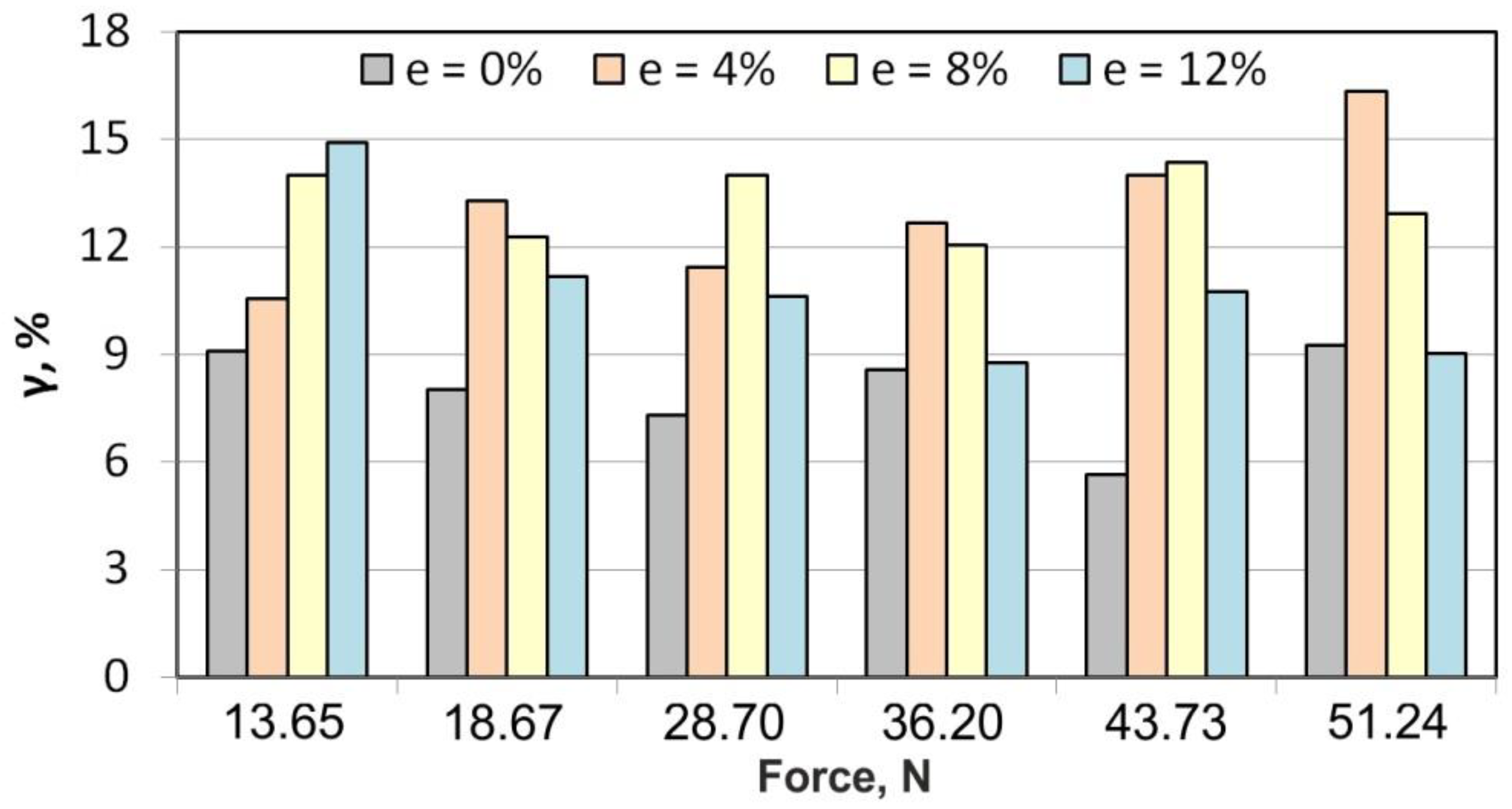
In order to determine the influence of the lubricant used on the lubrication efficiency, the lubrication factor γ was proposed according to the relationship:
The lubrication efficiency of as-received sheets varied in the range of 5.6–9.3% (Figure 6). In general, the lowest efficiency of reducing the coefficient of friction by the machine oil used was recorded for this state of the sheet. Practically, across the whole range of forces, the lubrication efficiency of the as-received sheet varied between 7.32 and 9.26%. Only for a force, FN = 43.73 N, was there a sharp local decrease in lubrication efficiency.
At low force values, the efficiency of lubrication is related to the volume of open oil pockets [39,40], which are the reservoir of lubricant, as well as the share of the mechanical interaction of the rough surface asperities. This mechanism is especially dominant in the initial friction stage when non-deforming surface asperities cooperate and overlap. The local reduction in lubrication efficiency may be related to the change of the dominant friction mechanism into mechanical surface flattening and strong ploughing of the sheet. By increasing the force value to FN = 51.24 N, the lubricant pressure was high enough to create an “oil cushion” effectively separating the interacted surfaces despite the high frictional resistance of the soft zinc layer.
The lubrication of pre-strained sheets was more effective than that of as-received sheets. The lubrication efficiency of the pre-strained sheet with ε = 4% was between 10.5% and 16.3%, with a trend of increasing lubrication efficiency with increasing force. The lubrication efficiency of the pre-strained sheet with ε = 8% showed an approximately constant trend in the entire range of applied forces and was between 12.1% and 14.0%. Different behaviour can be seen for pre-strained sheets with ε = 12%. Under these conditions, there was a trend of decreasing efficiency from 14.9% for FN = 13.65 N to 9.03% for FN = 51.24 N.
In the case of zinc-coated sheets, the basic feature of the frictional surface is the highly plastic properties of zinc. The directional surface topography, which was generated as a result of the uniaxial tensile test of the base metal under pressure, was further changed. The nature of this change depended on the degree of initial deformation of the sheet.
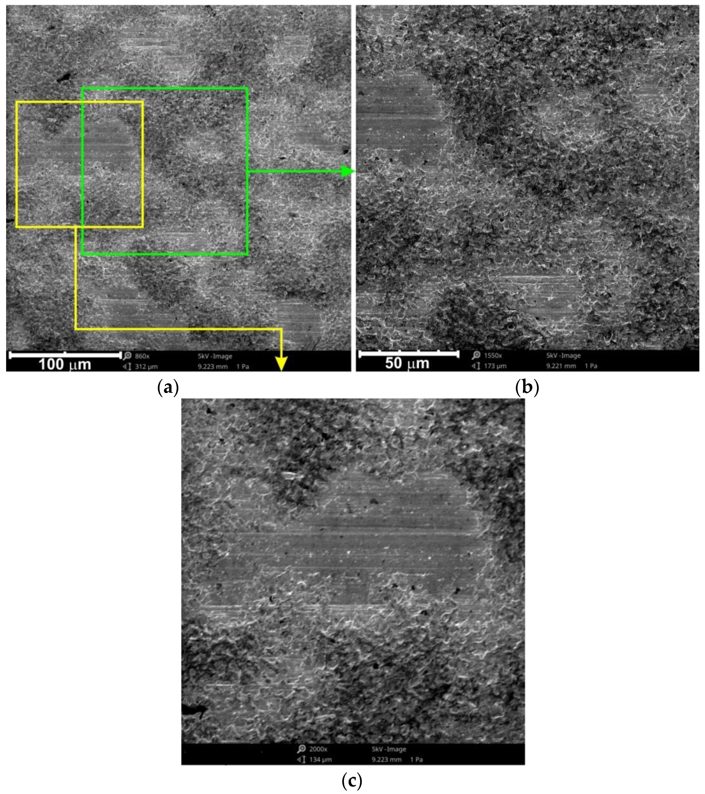
SEM analyses of the as-received sheets tested in dry friction conditions (Figure 7) revealed quite a large flattening of the surface roughness asperities. The initial protective zinc layer was very non-uniform with large grain coarseness. Only the highest surface asperities had been flattened. Furthermore, scratches and grooves are visible, possibly caused by build-ups on the counter-specimen surface. Another mechanism related to the flattening of the sheet surface is the plastic deformation of the zinc layer and adhesion, especially at high values of the forces imposed by the counter-sample. In sheet metal forming processes, the dry friction coefficient is the result of two main mechanisms [41,42,43]: resistance resulting from the mechanical interaction of surface asperities as a result of flattening and ploughing, and adhesion occurring in the areas of real contact. Under the conditions of friction with lubrication (Figure 8), the adhesion phenomenon practically disappears, while the other two mechanisms are limited by the interaction of the lubricating film between the valleys in the surface topography. When loading, the asperities deform elastically and plastically, changing the topography of the surface. In the case of elastic-plastic metals, the increase in normal force during forced sliding movement causes an increase in the real contact area, which may lead to a reduction in the volume of closed lubricant pockets (cavities in the surface profile) [39,40].
Due to the high plasticity of the zinc layer, there were local closed oil pockets. However, on a larger surface, open oil pockets are observed in which no hydrostatic oil cushion separating interacting surfaces is formed. Therefore, the friction surface of as-received specimens does not differ qualitatively from the pre-strained surfaces subjected to dry friction. The oil was moved to the contact zone through the spaces between the surface asperities of the counter-sample. During the deformation process, the lubricant changes the surface topography and the flow character of the deformed metal, reduces the unit pressure, reduces the coefficient of friction and improves the surface quality of the product.
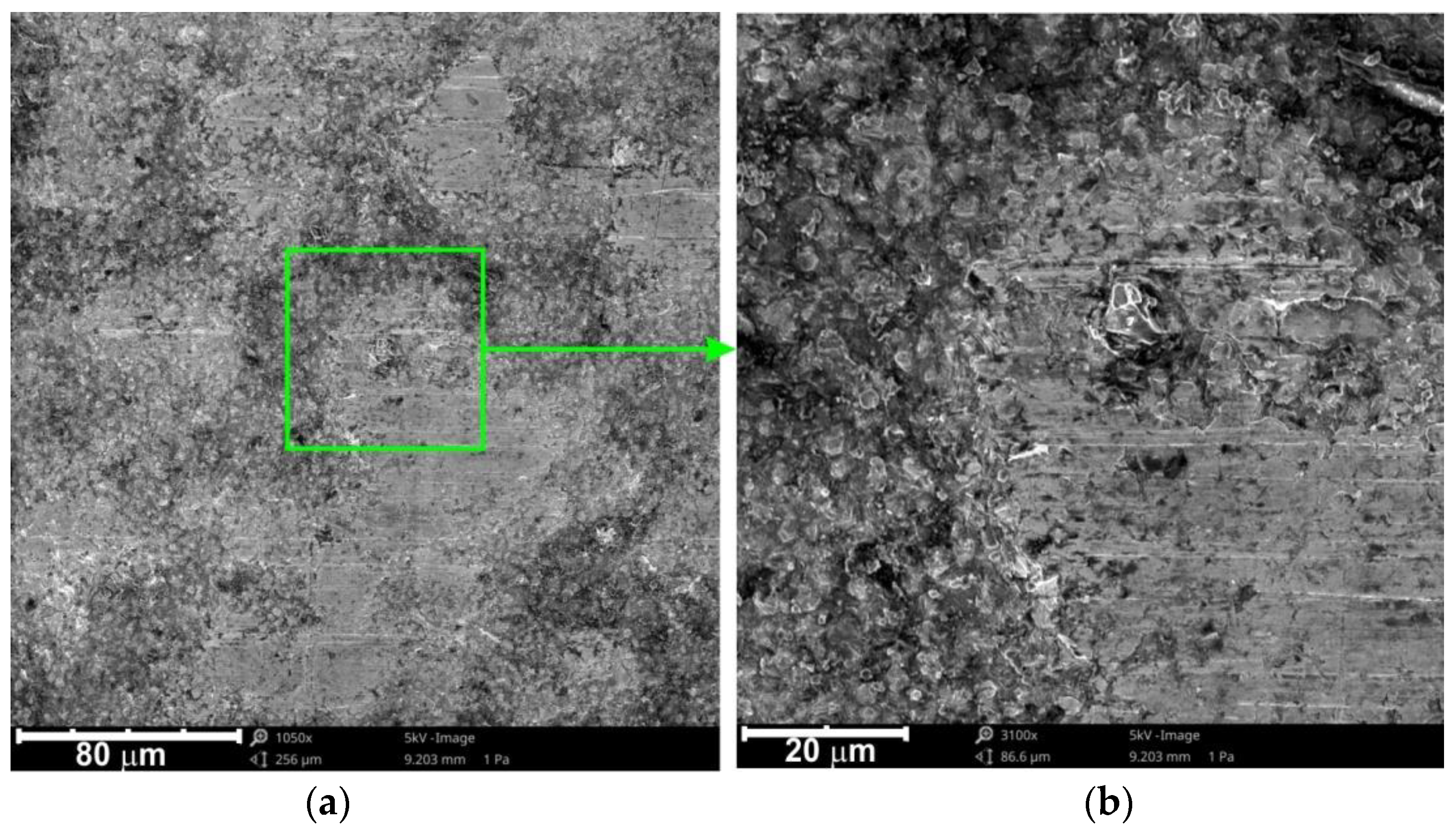
Figure 9 and Figure 10 show the SEM micrograph of the surface of the specimen pre-strained at 4%. The samples after plastic deformation showed a more uniform external surface topography compared to the as-received materials. Lubrication of the sheet surface allowed a reduction of the grooving mechanism of the sheet surface (Figure 10) compared to dry friction conditions (Figure 9). For the samples pre-strained at 4%, the skewness Rsk value decreases with increasing normal force FN (Table 4). The use of surfaces with higher kurtosis and more negative skewness is reflected in lower friction [39].
The load conditions used in the tests did not allow fully lubricated conditions with the presence of closed oil pockets to form on the dominant surface. In conditions of surface dominance of open lubricant pockets, the load is mainly transferred as a result of metallic contact of the asperities of the parts in contact, leading to a flattening of the surface asperities and, consequently, an increase in the real contact area.
For the samples pre-strained at 12%, there was a trend decreasing of skewness Rsk with increasing normal force FN (Table 5) as a result of the intense flattening of the surface asperities. Comparing the pre-strained sheet with specimens subjected to the friction process, the value of the kurtosis Rku decreases.
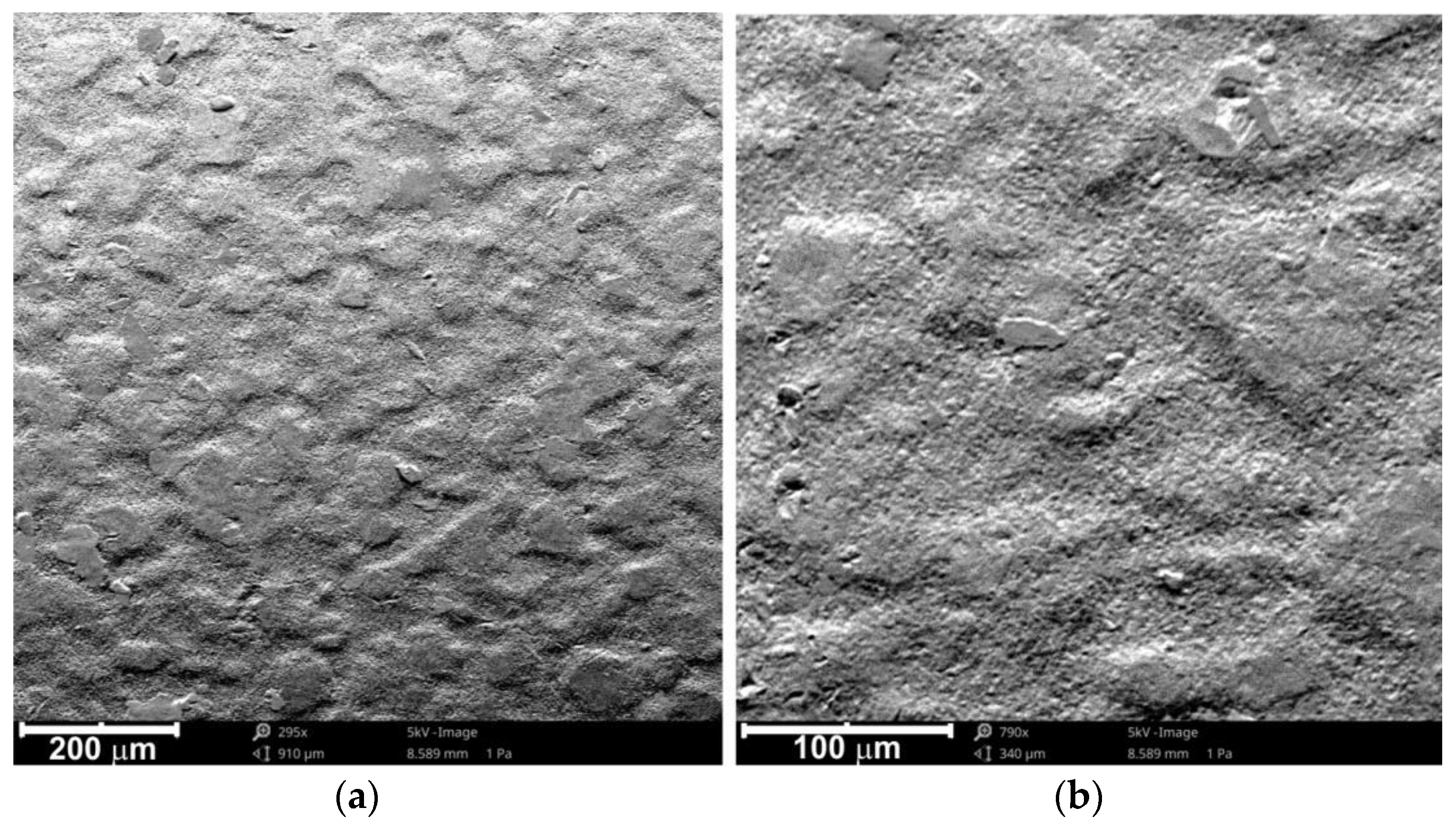
There are distinct hills between which there are open oil pockets (Figure 11). Abrasive wear is a phenomenon accompanying the friction process, which is defined as a set of phenomena occurring in the contact areas of two bodies leading to micro-cutting, shearing or detachment of surface asperities. Abrasive wear does not only concern the surface of the tool but also the surface of the sheet. The hard particles separated from the surface of the tool can act as an abrasive in contact with the workpiece of much lower hardness. Particles of the deformable material with much lower tool hardness may adhere to the valleys in the tool surface. In this way, adhesive bonding of the same materials passing one another can locally occur. This mechanism is especially important during the deformation of sheets covered with a soft layer of anti-corrosion coating, usually zinc.
4. Conclusions
This article presents friction test results describing the friction conditions that occur in the sheet metal forming process of the LITECOR® steel/polymer/steel sandwich material. Based on the results of the strip drawing test commonly used in the analysis of friction in SMF, the following conclusions can be drawn:
- The coefficient of friction declined to a minimum as the force increased.
- The highest values of the coefficient of friction were observed with as-received sheets. The high hills observed in the surface topography increase the share of the mechanical interactional mechanisms of flattening and ploughing of the soft sheet surface by the hard asperities of the counter sample surface.
- Apart from the friction process under the conditions of the lowest force analysed (FN = 13.65 N), the lowest value of the COF was observed for pre-strained sheets deformed with ε = 12%.
- Due to the high proportion of mechanical interactions of the counter sample roughness asperities in contact with the soft zinc protective layer, the worst efficiency of lubrication was seen in the as-received sheets.
- The lubrication efficiency of the pre-strained sheets at ε = 12% decreases with an increase in force. A trend for an increase in the lubrication efficiency with an increase in force was observed in the case of sheets pre-strained at ε = 4%.
Author Contributions
Conceptualization, T.T. and A.K.; methodology, T.T. and A.K.; validation, T.T., A.K. and J.S.; investigation, T.T. and A.K.; data curation, T.T., A.K. and J.S.; writing—original draft preparation, T.T.; writing—review and editing, T.T.; project administration, J.S.; funding acquisition, J.S. All authors have read and agreed to the published version of the manuscript.
Funding
The authors are grateful for the support in the experimental work to the Grant Agency of the Ministry of Education, Science, Research, and Sport of the Slovak Republic (grant number VEGA 1/0259/19).
Data Availability Statement
The data presented in this study are available on request from the corresponding author.
Acknowledgments
There are no issues to acknowledge.
Conflicts of Interest
The authors declare no conflict of interest.
References
- Rajak, D.K.; Pagar, D.D.; Menezes, P.L.; Linul, E. Fiber-Reinforced Polymer Composites: Manufacturing, Properties, and Applications. Polymers 2019, 11, 1667. [Google Scholar] [CrossRef] [PubMed] [Green Version]
- Deng, S.; Djukic, L.; Paton, R.; Ye, L. Thermoplastic–epoxy interactions and their potential applications in joining composite structures—A review. Compos. Part A Appl. Sci. Manuf. 2015, 68, 121–132. [Google Scholar] [CrossRef]
- Sinmazçelik, T.; Avcu, E.; Bora, M.Ö.; Çoban, O. A review: Fibre metal laminates, background, bonding types and applied test methods. Mater. Des. 2021, 32, 3671–3685. [Google Scholar] [CrossRef]
- Ramnath, B.V.; Alagarraja, K.; Elanchezhian, C. Review on Sandwich Composite and their Applications. Mater. Today Proc. 2019, 16, 859–864. [Google Scholar] [CrossRef]
- Trzepieciński, T.; Najm, S.M.; Sbayti, M.; Belhadjsalah, H.; Szpunar, M.; Lemu, H.G. New Advances and Future Possibilities in Forming Technology of Hybrid Metal–Polymer Composites Used in Aerospace Applications. J. Compos. Sci. 2021, 5, 217. [Google Scholar] [CrossRef]
- Abdullah, M.; Cantwell, W. The Impact Resistance of Polypropylene-Based Fibre–Metal Laminates. Compos. Sci. Technol. 2006, 66, 1682–1693. [Google Scholar] [CrossRef]
- Pan, L.; Ali, A.; Wang, Y.; Zheng, Z.; Lv, Y. Characterization of Effects of Heat Treated Anodized Film on the Properties of Hygrothermally Aged AA5083-Based Fiber-Metal Laminates. Compos. Struct. 2017, 167, 112–122. [Google Scholar] [CrossRef]
- Woizeschke, P.; Vollertsen, F. Fracture Analysis of Competing Failure Modes of Aluminum-CFRP Joints Using Three-Layer Titanium Laminates as Transition. J. Mater. Eng. Perform. 2015, 24, 3558–3572. [Google Scholar] [CrossRef]
- Bikakis, G.S.E.; Dimou, C.D.; Sideridis, E.P. Ballistic impact response of fiber–metal laminates and monolithic metal plates consisting of different aluminum alloys. Aerosp. Sci. Technol. 2017, 69, 201–208. [Google Scholar] [CrossRef]
- Akula, S.; Bolar, G. Comparative Evaluation of Machining Processes for Making Holes in GLARE Fiber Metal Laminates. Mater. Today Proc. 2021, 46, 9126–9131. [Google Scholar] [CrossRef]
- Sadighi, M.; Alderliesten, R.C.; Benedictus, R. Impact resistance of fiber-metal laminates: A review. Int. J. Impact Eng. 2012, 49, 77–90. [Google Scholar] [CrossRef]
- Burchitz, I.A.; Boesenkool, R.S.; van der Zwaag, S.; Tassoul, M. Highlights of designing with Hylite—A new material concept. Mater. Sci. Des. 2005, 26, 271–279. [Google Scholar] [CrossRef]
- Dibond-Broschüre; 3A Composites GmbH: Singen, Germany, 2010; pp. 1–28. Available online: https://www.almet-benelux.eu/l/library/download/urn:uuid:31fd3099-890b-4cd1-b63d-4b2ce7cd22af/dibond+broschuere+2017+en_almet.pdf (accessed on 12 January 2022).
- Carradò, A.; Faerber, J.; Niemeyer, S.; Ziegmann, G.; Palkowski, H. Metal/polymer/metal hybrid systems: Towards potential formability applications. Compos. Struct. 2011, 93, 715–721. [Google Scholar] [CrossRef]
- Palkowski, H.; Carradò, A. Three-layered sandwich material for lightweight applications. Emerg. Mater. Res. 2014, 3, 130–135. [Google Scholar] [CrossRef]
- Dibond. Available online: https://www.antalis.co.uk/business/en/sites/UK_Antalis_New/home/popular-brands/dibond.html (accessed on 12 January 2022).
- Hufenbach, W.; Jaschinski, J.; Weber, T.; Weck, D. Numerical and experimental investigations on HYLITE sandwich sheets as an alternative sheet metal. Arch. Civ. Mech. Eng. 2008, 8, 67–80. [Google Scholar] [CrossRef]
- Harhash, M.; Kuhtz, M.; Richter, J.; Hornig, A.; Gude, M.; Palkowski, H. Influence of Adhesion Properties on the Crash Behavior of Steel/Polymer/Steel Sandwich Crashboxes: An Experimental Study. Metals 2021, 11, 1400. [Google Scholar] [CrossRef]
- Richter, J.; Kuhtz, M.; Hornig, A.; Harhash, M.; Palkowski, H.; Gude, M. A Mixed Numerical-Experimental Method to Characterize Metal-Polymer Interfaces for Crash Applications. Metals 2021, 11, 818. [Google Scholar] [CrossRef]
- ThyssenKrupp Steel Europe AG. BONDAL® Composite Material with Structure-Borne Sound Damping Properties. Available online: https://www.thyssenkrupp-steel.com/en/products/composite-material/overview-composite-material.html (accessed on 14 January 2021).
- Kustroń, P.; Korzeniowski, M.; Piwowarczyk, T.; Sokołowski, P. Development of Resistance Spot Welding Processes of Metal–Plastic Composites. Materials 2021, 14, 3233. [Google Scholar] [CrossRef]
- Hybrix™ = ∑[Lightweight, Formable, Strong, Eco-Friendly]. Available online: https://www.lamera.se/ (accessed on 14 January 2021).
- Hammarberg, S.; Kajberg, J.; Larsson, S.; Moshfegh, R.; Jonsén, P. Novel Methodology for Experimental Characterization of Micro-Sandwich Materials. Materials 2021, 14, 4396. [Google Scholar] [CrossRef]
- Sokolova, O.A.; Kühn, M.; Palkowski, H. Deep drawing properties of lightweight steel/polymer/steel sandwich composites. Arch. Civ. Mech. Eng. 2012, 12, 105–112. [Google Scholar] [CrossRef]
- Mosse, L.; Compston, P.; Cantwell, W.J.; Cardew-Hall, M.; Kalyanasundaram, S. The development of a finite element model for simulating the stamp forming of fibre-metal laminates. Compos. Struct. 2006, 75, 298–304. [Google Scholar] [CrossRef]
- Murtagh, A.M.; Lennon, J.J.; Mallon, P.J. Surface friction effects related to pressforming of continuous fibre thermoplastic composites. Compos. Manuf. 1995, 6, 169–175. [Google Scholar] [CrossRef]
- Rajabi, A.; Kadkhodayan, M. An Investigation into the Deep Drawing of Fiber-metal Laminates based on Glass Fiber Reinforced Polypropylene. Int. J. Eng. 2014, 27, 349–358. [Google Scholar]
- Wollmann, T.; Hahn, M.; Wiedemann, S.; Zeiser, A.; Jaschinski, J.; Modler, N.; Ben Khalifa, N.; Meißen, F.; Paul, C. Thermoplastic fibre metal laminates: Stiffness properties and forming behaviour by means of deep drawing. Arch. Civ. Mech. Eng. 2018, 18, 442–450. [Google Scholar] [CrossRef]
- Sexton, A.; Venkatesan, S.; Cantwell, W.; Kalyanasundaram, S. Experimental and numerical characterisation of the out-of-plane stretch forming of a fibre metal laminate based on a self-reinforced polypropylene composite. In Proceedings of the ECCM15-15th European Conference on Composite Materials, Venice, Italy, 24–28 June 2012. [Google Scholar]
- Hahn, M.; Khalifa, N.B.; Shabaninejad, A. Prediction of Process Forces in Fiber Metal Laminate Stamping. J. Manuf. Sci. Eng. 2018, 140, 031002. [Google Scholar] [CrossRef]
- DharMalingam, S.; Compston, P.; Kalyanasundaram, S. Process Variables Optimisation of Polypropylene Based Fibre-Metal Laminates Forming Using Finite Element Analysis. Key Eng. Mater. 2009, 410–411, 263–269. [Google Scholar] [CrossRef]
- ten Thije, R.H.W.; Akkerman, R.; van der Meer, L.; Ubbink, M.P. Tool-Ply Friction in Thermoplastic Composite Forming. Int. J. Mater. Form. 2008, 1, 953–956. [Google Scholar] [CrossRef]
- Wendel, E. Evaluation of Potential for Metal/Polymer/Metal Sandwich Material as Outer Panels for Trucks. Available online: https://www.diva-portal.org/smash/get/diva2:1300622/FULLTEXT02 (accessed on 23 April 2022).
- Jonnson, S. Corrosion of Zinc in the Automotive Environment. Master’s Thesis, Swerea-KIMAB, Kista, Sweden, 2012. [Google Scholar]
- Kustroń, P.; Korzeniowski, M.; Piwowarczyk, T.; Sokołowski, P. Hybrid Welding of Metal-Polymer Composites with a Non- Conducting Polymer Layer. Bull. Inst. Weld. 2021, 4, 33–40. [Google Scholar] [CrossRef]
- Forster, J. The Sandwich Effect, Compact Steel. ThyssenKrupp Cust. Mag. 2014, 1, 8–11. [Google Scholar]
- EN 10346; Continuously Hot-Dip Coated Steel Flat Products for Cold Forming. Technical Delivery Conditions. European Committee for Standardization: Brussels, Belgium, 2015.
- Cillaurren, J.; Galdos, L.; Sanchez, M.; Zabala, A.; de Argandoña, S.; Mendiguren, J. Contact pressure and sliding velocity ranges in sheet metal forming simulations. In Proceedings of the 24th International Conference on Material Forming ESAFORM 2021, Liège, Belgium, 14–16 April 2021. [Google Scholar]
- Trzepieciński, T.; Fejkiel, R. On the influence of deformation of deep drawing quality steel sheet on surface topography and friction. Tribol. Int. 2017, 115, 78–88. [Google Scholar] [CrossRef]
- Gåård, A. Wear in Sheet Metal Forming. Licentiate Thesis, Kalstad University, Karlstad, Sweden, 2018. [Google Scholar]
- Carlsson, P. Surface Engineering in Sheet Metal Forming. Ph.D. Thesis, Acta Universitatis Upsaliensis, Uppsala, Sweden, 2005. [Google Scholar]
- Hol, J.; Meinders, V.T.; de Rooij, M.B.; van den Boogaard, A.H. Multi-scale friction modeling for sheet metal forming: The boundary lubrication regime. Tribol. Int. 2015, 81, 112–128. [Google Scholar] [CrossRef]
- Popov, V.L. Coulomb’s law of friction. In Contact Mechanics and Friction, Physical Principles and Applications; Springer: Berlin/Heidelberg, Germany, 2010; pp. 133–154. [Google Scholar]
Figure 1.
Simulator of the strip drawing test.

Figure 2.
Force–deflection characteristics of the spring.

Figure 3.
Force-displacement curves of Litecore plate.

Figure 4.
SEM micrographs of the (a) as-received surface and the surfaces of pre-strained sheets with an elongation of (b) 4%, (c) 8% and (d) 12%.
Figure 4.
SEM micrographs of the (a) as-received surface and the surfaces of pre-strained sheets with an elongation of (b) 4%, (c) 8% and (d) 12%.

Figure 5.
Effect of force on the coefficient of friction µav for tests realised in (a) dry friction and (b) lubricated conditions.
Figure 5.
Effect of force on the coefficient of friction µav for tests realised in (a) dry friction and (b) lubricated conditions.

Figure 6.
Effectiveness of lubrication by machine oil L-AN46.

Figure 7.
SEM micrographs of the surface of the as-received sheet metal tested in dry friction conditions and in the following conditions: (a,b) FN = 28.70 N; (c,d) FN = 43.73 N at different magnifications.
Figure 7.
SEM micrographs of the surface of the as-received sheet metal tested in dry friction conditions and in the following conditions: (a,b) FN = 28.70 N; (c,d) FN = 43.73 N at different magnifications.

Figure 8.
SEM micrographs of the surface of the as-received sheet metal tested in lubricated conditions and with a force FN = 36.20 N; magnifications: (a) ×1300 and (b) ×2650.
Figure 8.
SEM micrographs of the surface of the as-received sheet metal tested in lubricated conditions and with a force FN = 36.20 N; magnifications: (a) ×1300 and (b) ×2650.

Figure 9.
SEM micrographs of the surface of the pre-strained specimen (ε = 4%) tested in dry friction conditions and with a force FN = 43.73 N; magnifications: (a) ×1050 and (b) ×3100.
Figure 9.
SEM micrographs of the surface of the pre-strained specimen (ε = 4%) tested in dry friction conditions and with a force FN = 43.73 N; magnifications: (a) ×1050 and (b) ×3100.

Figure 10.
(a) SEM micrograph of the surface of the pre-strained specimen (ε = 4%) tested in lubricated conditions and with a force of FN = 18.67 N; (b,c) detailed views of (a).
Figure 10.
(a) SEM micrograph of the surface of the pre-strained specimen (ε = 4%) tested in lubricated conditions and with a force of FN = 18.67 N; (b,c) detailed views of (a).

Figure 11.
SEM micrographs of the surface of a pre-strained specimen (ε = 12%) tested in dry friction conditions with a force FN = 13.65 N; magnifications: (a) ×295 and (b) ×790.
Figure 11.
SEM micrographs of the surface of a pre-strained specimen (ε = 12%) tested in dry friction conditions with a force FN = 13.65 N; magnifications: (a) ×295 and (b) ×790.


Table 1.
Selected mechanical properties of the zinc coating.
| Yield Stress, MPa | Tensile Strength, MPa | Elongation, % | Modulus of Elasticity, MPa | Hardness HV |
|---|---|---|---|---|
| 10 | 26 | 12 | 7 × 10⁴ | 30 |
Table 2.
Chemical composition (max.) of the HX220YD steel (wt.%).
| C | Mn | Si | Al | Ti | Nb | Cu | P | S |
|---|---|---|---|---|---|---|---|---|
| 0.01 | 0.9 | 0.2 | 0.1 | 0.12 | 0.09 | 0.2 | 0.08 | 0.025 |
Table 3.
Selected mechanical properties of the HX220YD steel.
| A, % | Rm, MPa | Rp0.2, MPa |
|---|---|---|
| 32 | 340–420 | 220–280 |
Table 4.
Variation of skewness Rsk and kurtosis Rku as a result of the friction process in specimens pre-strained at 4%.
Table 4.
Variation of skewness Rsk and kurtosis Rku as a result of the friction process in specimens pre-strained at 4%.
| Parameter | Pre-Strained Sheet | Normal Force FN, N | |||||
|---|---|---|---|---|---|---|---|
| 13.65 | 18.67 | 28.70 | 36.20 | 43.73 | 51.24 | ||
| Rku | 1.83 | 1.98 | 1.94 | 2.35 | 2.04 | 2.05 | 2.91 |
| Rsk | −0.042 | −0.123 | −0.232 | −0.322 | −0.305 | −0.384 | −0.846 |
Table 5.
Variation of skewness Rsk and kurtosis Rku as a result of the friction process in specimens pre-strained at 12%.
Table 5.
Variation of skewness Rsk and kurtosis Rku as a result of the friction process in specimens pre-strained at 12%.
| Parameter | Pre-Strained Sheet | Normal Force FN, N | |||||
|---|---|---|---|---|---|---|---|
| 13.65 | 18.67 | 28.70 | 36.20 | 43.73 | 51.24 | ||
| Rku | 2.75 | 1.79 | 2.54 | 1.96 | 2.21 | 2.18 | 2.47 |
| Rsk | −0.123 | −0.184 | −0.339 | −0.283 | −0.415 | −0.516 | −0.675 |
Publisher’s Note: MDPI stays neutral with regard to jurisdictional claims in published maps and institutional affiliations. |
© 2022 by the authors. Licensee MDPI, Basel, Switzerland. This article is an open access article distributed under the terms and conditions of the Creative Commons Attribution (CC BY) license (https://creativecommons.org/licenses/by/4.0/).
Share and Cite
MDPI and ACS Style
Trzepieciński, T.; Kubit, A.; Slota, J. Assessment of the Tribological Properties of the Steel/Polymer/Steel Sandwich Material LITECOR. Lubricants 2022, 10, 99. https://0-doi-org.brum.beds.ac.uk/10.3390/lubricants10050099
AMA Style
Trzepieciński T, Kubit A, Slota J. Assessment of the Tribological Properties of the Steel/Polymer/Steel Sandwich Material LITECOR. Lubricants. 2022; 10(5):99. https://0-doi-org.brum.beds.ac.uk/10.3390/lubricants10050099
Chicago/Turabian StyleTrzepieciński, Tomasz, Andrzej Kubit, and Ján Slota. 2022. "Assessment of the Tribological Properties of the Steel/Polymer/Steel Sandwich Material LITECOR" Lubricants 10, no. 5: 99. https://0-doi-org.brum.beds.ac.uk/10.3390/lubricants10050099
Note that from the first issue of 2016, this journal uses article numbers instead of page numbers. See further details here.