1. Introduction
Sharp contact experiments are performed for determination of the material properties of the tested materials. It is also possible to determine field variables such as for example residual stresses. Global quantities determined during a normal indentation test are hardness, H, and the indentation load, F, versus indentation depth curve, h. In case of scratch testing, the hardness is divided into a normal component and a tangential component. The normal hardness values are defined as the mean contact pressure here and in the sequel. Another global quantity of importance at contact testing is the area of contact. However, the hardness is the parameter most often used for material characterization.
At sharp indentation of elastic or standard (von Mises) elastoplastic materials relations between contact quantities and material properties are available and results by Sneddon [
1], Tabor [
2] and Johnson [
3,
4] have been verified using finite element simulations. The state of the art as regards correlation of sharp indentation of standard elastoplastic materials will be discussed below.
For other types of sharp contact problems, similar types of efforts exists. It has been shown by for example Bucaille [
5] and Wredenberg and Larsson [
6] that corresponding relations, as present at normal indentation testing, exist at scratching with a sharp indenter. Furthermore, normal indentation of materials described by Drucker–Prager plasticity [
7] have been analyzed by, for example, Narasimhan [
8], Zhang et al. [
9] and Fornell et al. [
10]. The latter studies, [
8,
9,
10], are devoted towards elastoplastic contact when elastic and plastic deformation in the contact region are of the same magnitude. Such analyses are of great interest presently.
When material characterization by sharp contact testing is at issue, rigid-plastic contact is most often considered. In such a situation, the actual correlation relations will include only the constitutive parameters pertinent to the plastic behavior and, furthermore, their functional form are rather simple. Accordingly, it was already found by Tabor [
2] that at rigid-plastic sharp normal indentation, the relation applies at ideal plasticity where
σy is the material yield stress. At strain-hardening plasticity,
σy is replaced by
σrep, which is the material flow stress at a representative value of the effective (accumulated) plastic strain
εp. For most sharp indenters the constant
C takes on values close to three. It was shown in [
6,
11] that Equation (1) also applies at scratching of classical elastoplastic materials but with a somewhat lower value on
C.
A recent very interesting investigation was presented by Dahlberg et al. [
12]. In this study sharp indentation of Drucker–Prager [
7] rigid-plastic materials were examined based on an approach similar to the one presently relied upon. In short, the elastoplastic solution presented in [
8] was then further developed to include also rigid-plastic contact. This approach will be generalized in the present investigation.
Johnson [
3,
4] suggested based on cavity expansion solutions that the contact behavior is determined by the value on the (Johnson) parameter
In Equation (2),
E is Young’s modulus and
ν is Poisson’s ratio,
β is the angle between the (sharp) indenter and the undeformed surface and
σrep is the material flow stress at a representative value of the effective (accumulated) plastic strain
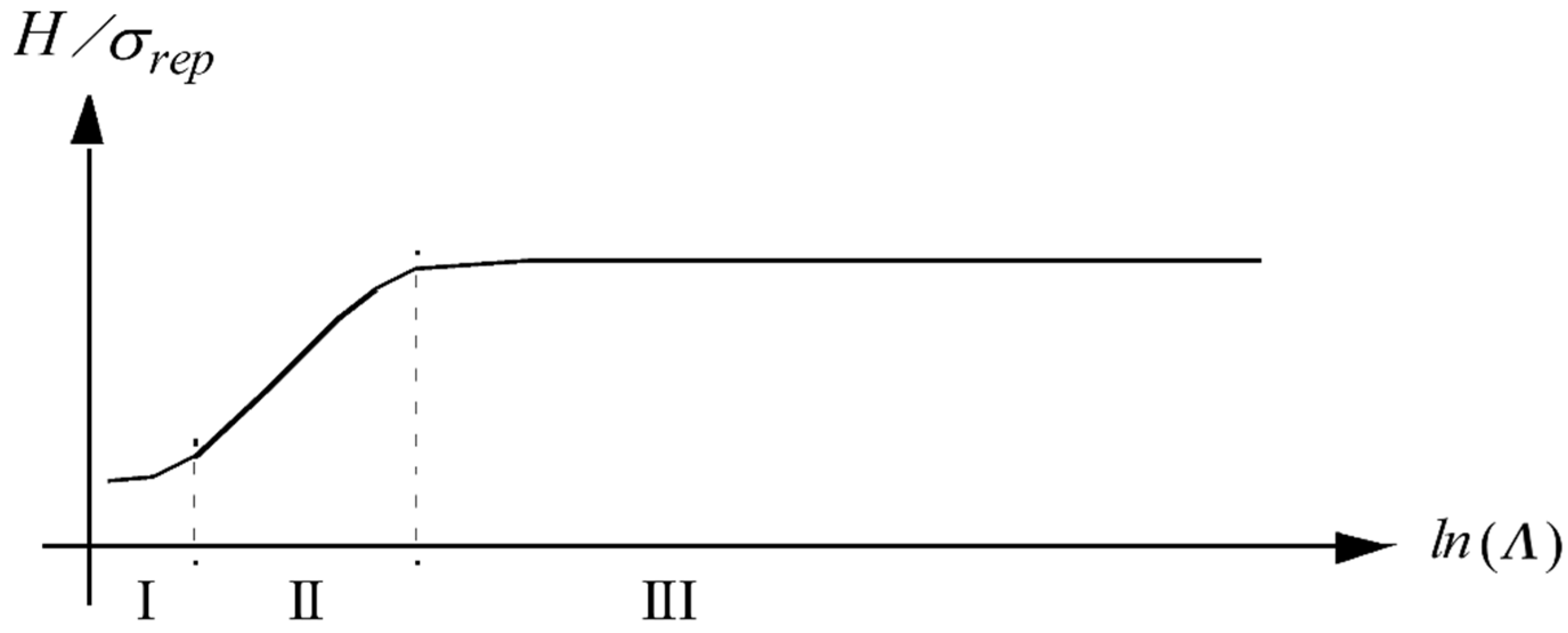
εp. Three indentation levels are noticeable as depicted in
Figure 1 and they are denoted level I (elastic contact)
Λ < 3, level II (elastic–plastic contact where
H ~ ln
Λ) and level III (rigid-plastic contact). In level III, Equation (1) according to Tabor [
2] is valid or, at strain hardening
Material characterization based on the contact area is much more involved, cf., e.g., [
13,
14,
15]. Indeed, such an approach is sometimes not of much practical use when generality is aimed at but can, when characterization is at issue, be a valuable complement to the hardness values. This feature will be mentioned below and discussed in more detail at the end of this paper.
Normally, when determining relations in the spirit of Equation (1) or Equation (3) for rigid-plastic contact, extensive experimental series are required in combination with dimensional considerations. However, a more general approach would be beneficial, and this is suggested and outlined presently. In short, to be discussed in more detail below, what is required in the analysis is a solution to the level II contact problem presenting at least the constitutive parameter dependence in this region and the value for the plastic zone size in the level III contact region. Three illustrative examples of the usefulness of the proposed approach are discussed. These three examples concerns (1) sharp indentation of von Mises plastic materials, (2) sharp indentation of Drucker–Prager plastic materials, and (3) scratching of von Mises plastic materials. In order to verify the theoretical approach, these results are compared with results from previous finite element simulations. Remembering the wealth of results available pertinent to sharp indentation of materials, no further finite element simulations were deemed necessary for this verification.
When it comes to problem (1), this is of course a very well-studied problem, as evident from the discussion above. Problem (2) is less investigated but rests on the results pertinent to cavity expansion models, as outlined above and in detail in
Section 3 and
Section 4 below. In these chapters, Problem (3) is also discussed in some detail. It should be emphasized that for the scratch problem, no fundamental cavity expansion solution exists, but instead the analysis is based on relations derived finite element results.
As for the advantages of the presently suggested approach, this concerns the fact that it eliminates the need for time-consuming numerical and/or experimental efforts to determine empirical rigid-plastic contact relations. Indeed, the dependence of constitutive parameters are directly determined as will be hopefully evident from the analysis below.
In the final part of this study, new results are presented based on the suggested approach. These results concern the constitutive parameter dependence of the relative contact area, pertinent to case (2). These results are compared with finite element simulations.
Concerning the application of the present results, these are pertinent to metals and alloys. However, they are also directly relevant for elastic–plastic crystalline materials as well as for powder materials [
16,
17] where the contact deformation regime is close to the rigid-plastic one.
2. Problem Formulation
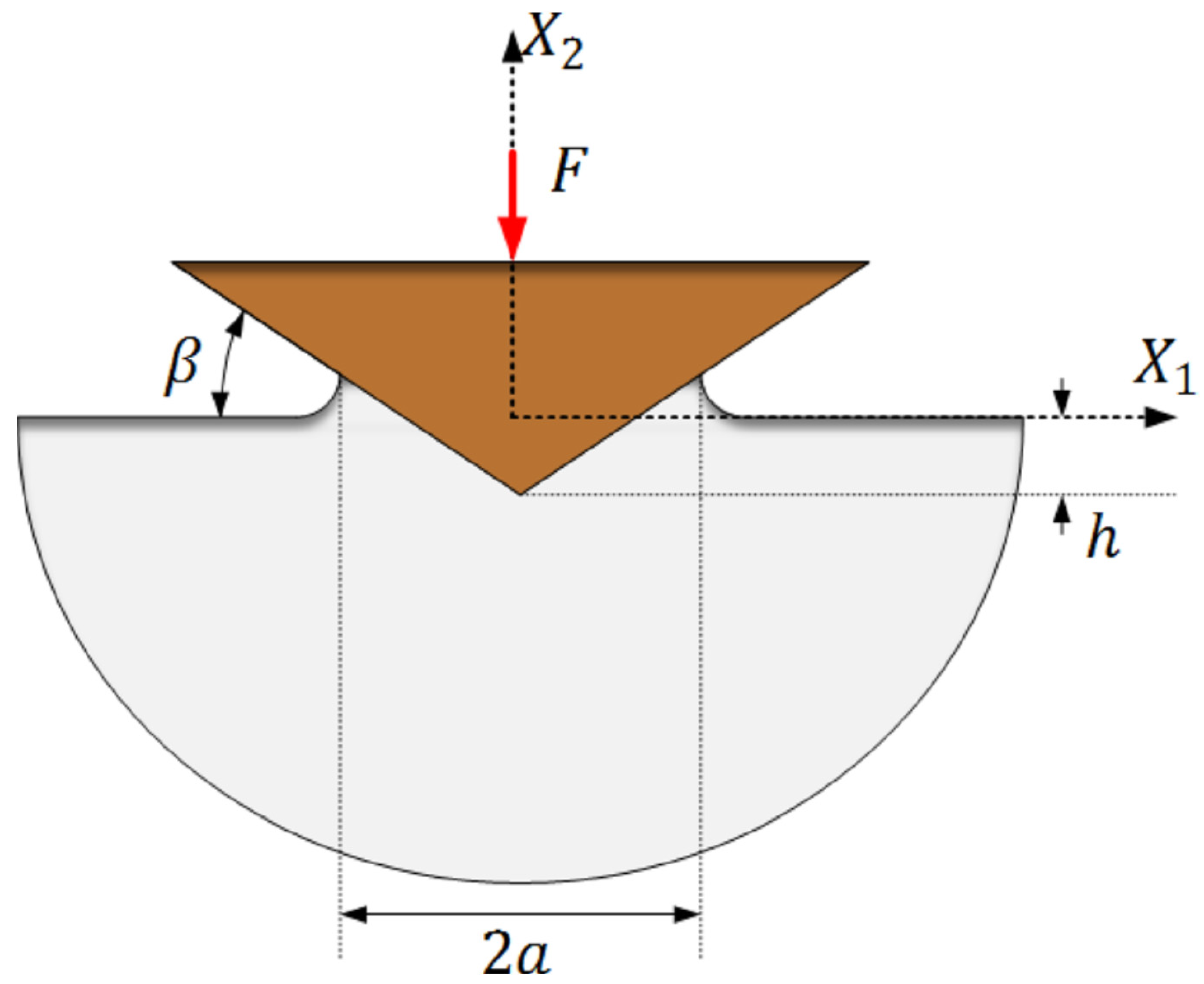
The problem at issue concerns sharp indentation of elastoplastic materials, pressure-sensitive or not. The contact loading is either normal (for example indentation), see
Figure 2 at cone indentation, or tangential (for example scratching), see
Figure 3.
In the simplest case, at conical indentation, a sharp rigid conical stylus with an angle of 22°, between the indenter and the undeformed surface, see
Figure 2, is used. The angle 22° is chosen in the present study as being the same as the corresponding angle at Vickers (sharp pyramid indenter with quadratic base) indentation. This indenter geometry will be adhered to throughout the investigation. It should be emphasized though that this is not a limitation of the present approach as the (sharp) indenter geometry only enters the equations through the Johnson parameter in Equation (2). In the presentation below,
h is the normal indentation depth in the
X2 direction (Cartesian coordinates are introduced in
Figure 2, and
A is the normally projected contact area between indenter and material. Quasi-static conditions are assumed and the dimensions of the contact region are very small compared to the size of the indented material specimen. Based on these restrictions, the problem is self-similar with no characteristic length present (as in most sharp contact problems) and this ensures that the (normal) hardness as well as the ratio
h/√A (where
√A should be interpreted as a characteristic contact length) are constant during the loading sequence of an indentation test on homogeneous and local materials. Here, and in the sequel, the normal hardness is defined as
where
F is the normal contact load, see
Figure 2. The tangential hardness is defined correspondingly, tangential load divided by tangential contact area, but this quantity is not of immediate interest presently.
It now seems appropriate to once again consider the results in
Figure 1. It is obvious that there is a rather sharp transition between the level II and level III contact regions. This indicates that the dependence of plastic constitutive properties in the rigid-plastic (level III) region can be determined from studying this transition zone and, in particular, relevant analytical solutions pertinent to level II contact. Such solutions are most frequently based on varieties of the expanding cavity solution as presented by, for example, Johnson [
3,
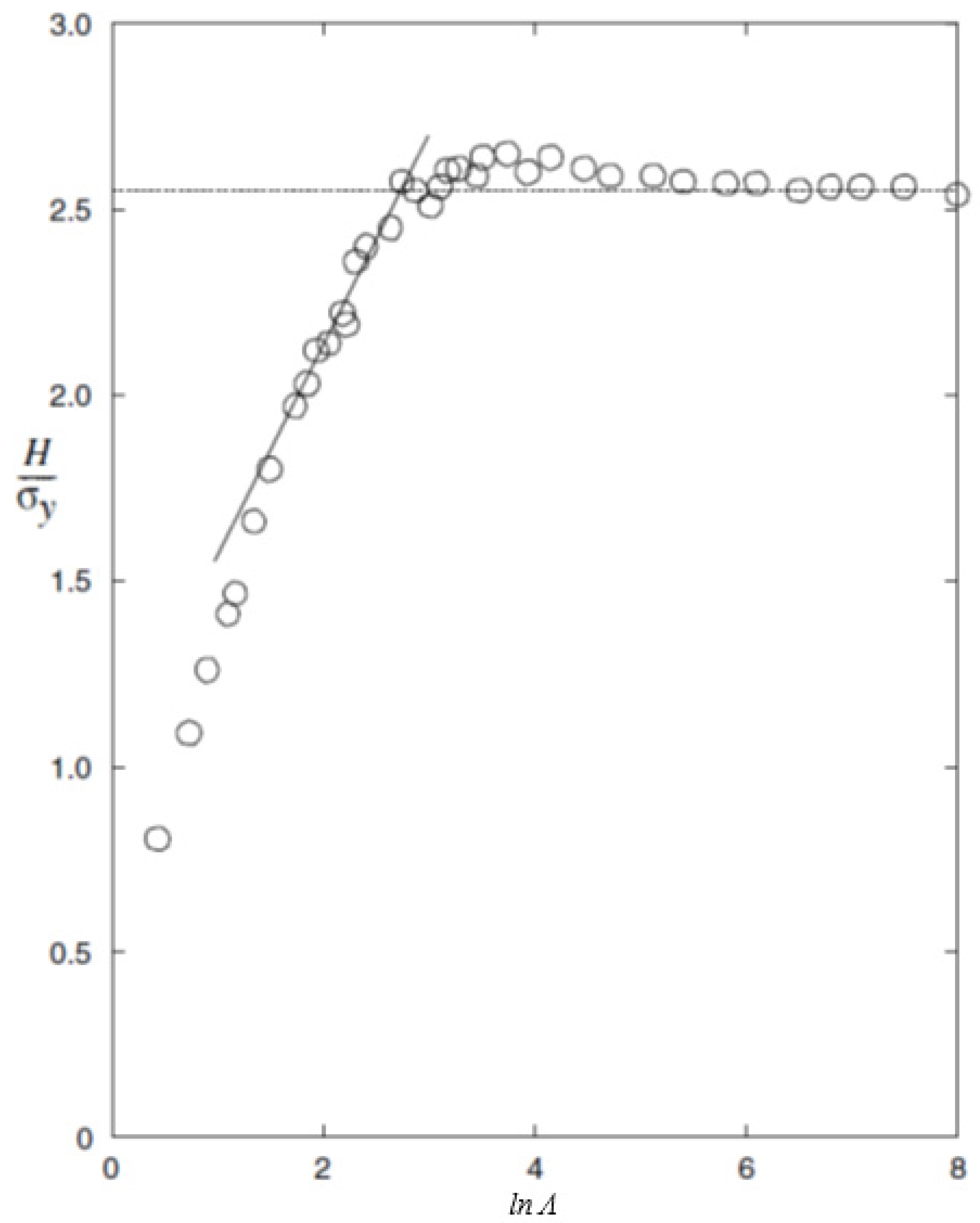
4], for classical elastoplastic materials. Some actual results are shown in
Figure 4, taken from [
15], and it can then be seen that the transition zone between level II and level III contact is in a practical case sharper than what is schematically seen in
Figure 1. Accordingly, with a proper scaling on the vertical axis, this would give a direct indication of the behavior (parameter dependence) in the rigid-plastic region. This is also the basis for the present approach.
Regarding the constitutive behavior, classical von Mises and Drucker–Prager elastoplasticity is assumed to prevail with a yield condition
where
σe is the von Mises effective stress,
σh is the hydrostatic stress, α is the pressure-sensitivity factor (α = 0 defines classical von Mises elastoplasticity) and
σ(
εp) is the flow stress in pure shear. The fundamental contact behavior for both classical von Mises and Drucker–Prager elastoplasticity materials is well described by the results shown in
Figure 4. At Drucker–Prager elastoplasticity, associativity of the flow rule is assumed. Large deformation theory was relied upon because such effects are significant at many contact problems, cf., e.g., [
11,
18]. At elastic loading, or unloading, a hypoelastic formulation of Hooke’s law was used. Kinematic hardening effects were not included in the analysis as only the loading part of the indentation test was of primary interest. The strain hardening behavior are based on a power law assumption according to
where
σ0 is the initial yield stress in pure shear,
εp is as previously stated the effective plastic strain and
ε0 and
n are material constants describing the plastic hardening.
In summary, the present analysis is restricted to quasi-static conditions and classical elastoplasticity and, as a result, strain rate effects are not included. Frictionless contact is assumed as a first approximation. The investigation is focused on level III contact conditions where the influence from elasticity on the hardness behavior is negligible.
3. Theoretical Foundation
In the case of classical von Mises plasticity it was shown by Johnson [
3,
4] that at elastic–plastic (level II) sharp indentation the material hardness is well described by the relation
where
The derivation leading to Equation (7) rests on the similarity of the stress fields at sharp indentation and taking advantage of the analysis of expansion of a pressurized spherical cavity in an elastic–ideally plastic material. The solution to the latter problem (in the context of indentation testing) was originally proposed by Bishop et al. [
19] and the effect from plastic strain hardening is accounted for by the representative stress
σrep. It has been shown with the aid of finite element calculations, cf., e.g., Larsson [
20], that the constants
C1 and
C2 in Equation (7) are not strictly independent of the strain-hardening characteristics. However, as the present investigation concerns rigid-plastic (level III) indentation this issue will not be dwelled upon further. It should be emphasized that at
Λ-values pertinent to the transition between level II and level III indentation Equations (3) and (7) obviously yield similar results.
The analysis by Johnson [
3,
4] was extended to pressure-sensitive materials, described by classical Drucker–Prager elastoplasticity, by Narasimhan [
8] and further discussed by Zhang et al. [
9] and Fornell et al. [
10]. The resulting expression for the hardness (mean contact pressure) in the case of cone indentation yields
at ideally plastic material behavior where
q = 3α/(1 + 2α). In (11),
is the radius of the plastic zone,
rp, nondimensionalized by the radius of contact
a. It should be noted that elastic effects are included in (9) only through
. As suggested by Larsson and Olsson [
21],
is defined as the plastic zone depth in the negative
X2-direction normal to the surface, see
Figure 2.
As it stands, Equation (9) describes the hardness at level II cone indentation accounting for pressure sensitivity through α but not for strain hardening. However, the latter feature can be accounted for in the same way as in case of von Mises plasticity with a representative stress measure σrep.
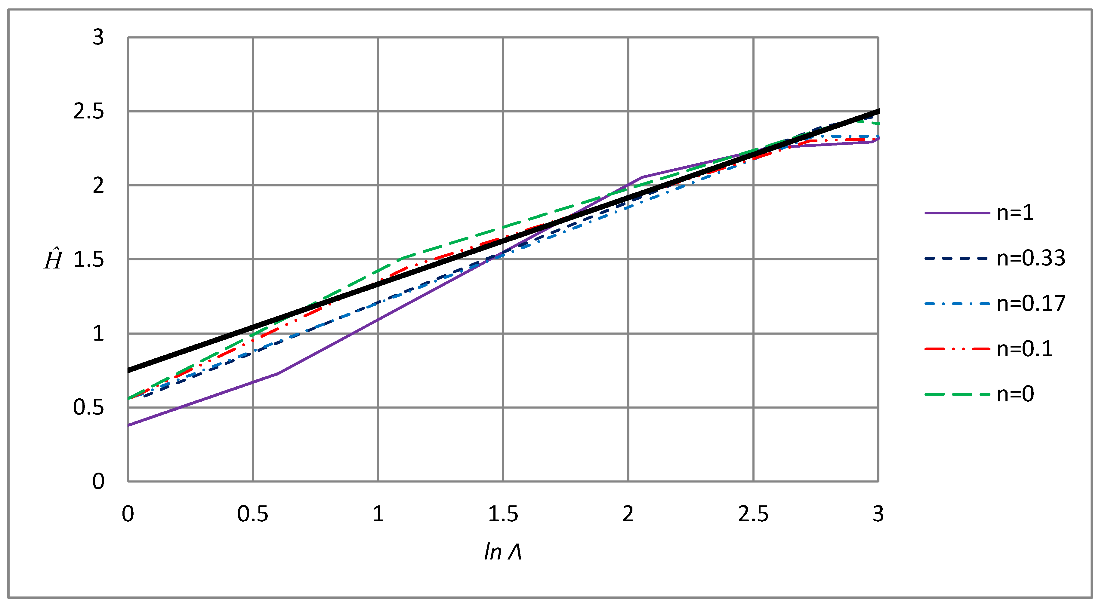
A further contact problem of interest here concerns scratching of materials. For simplicity, but not out of necessity, only the normal components at scratching will be discussed presently. The hardness as a function of
Λ is shown in
Figure 5 and
Figure 6, taken from [
11], with the result pertinent to contact at all levels. Again, a curve similar to the normal indentation results in
Figure 1 are found with a fairly sharp transition between level II, described by an equation in the spirit of Equation (7), and level III, described by an equation according to Equation (3) utilizing the concept of a representative stress. It should be noted though that, contrary to the situation at standard normal indentation, the representative stresses at level II and level III contact are taken at different representative values of the effective (accumulated) plastic strain
εp.
Having now discussed the three contact situations immediately at issue in the present study, and being representative for many similar problems in contact mechanics, it seems appropriate to discuss the present solution approach for rigid-plastic contact problems. In doing so, two important features should be directly stated, namely:
- 1.
The solution to the level II problem can be derived in many contact situations from the spherical cavity expansion solution, see for example [
3,
8]. This will give a semi-analytical expression for the hardness, among other variables, as function of
Λ, or alternatively
, and constitutive parameters pertinent to the material at issue. It should be emphasized that these variables are constant at sharp contact of materials with no characteristic length in the material model.
- 2.
A similar semi-analytical expression cannot be derived at level III contact as then a solution corresponding to the cavity expansion solution is not available. However, based on the fact that there are no characteristic length present in the problem for example can be easily determined from a very limited number of finite element calculations. Such calculations are nowadays a standard issue even at sharp contact.
Accordingly, level III contact conditions are enforced by introducing the rigid-plastic value on into the cavity expansion solution. The material parameter dependence in the rigid-plastic solutions are then immediately available. It should be emphasized that from experience, for simplicity, this can be achieved for ideally plastic material behavior, and strain hardening can be introduced, as in case of von Mises plasticity, in a standard manner solely by replacing the initial yield stress σy with a representative stress σrep.
4. Results and Discussion
In this section, the three previously listed contact problems will be analyzed and discussed based on the solution approach described above. These three contact problems concern the following:
Sharp indentation of von Mises plastic materials.
Sharp indentation of Drucker–Prager plastic materials.
Scratching of von Mises plastic materials.
Furthermore, at the end of this section, new results are presented based on the suggested approach. Here, the constitutive parameter dependence of the relative contact area, pertinent to case (2) are determined. These analytical results are then compared with finite element simulations with the numerical approach outlined in, for example, [
15].
The first contact problem, sharp indentation of von Mises plastic materials (1) above, is of course extremely well known. This was also the perhaps first example of using the so-called cavity expansion solution in order to determine the behavior at level II contact (Johnson [
3,
4]). This will result in Equations (7) and (8). In this rather straightforward example, it is not difficult to determine the constitutive parameter dependence in the level III contact regime. According to Johnson [
3,
4], Equation (7) can instead be expressed using the plastic zone size ratio
as
It has been shown by Larsson and Olsson [
21] that at rigid–ideally plastic contact,
approximately takes on the value 2 which, when inserted into Equation (11), with the choice of parameters
K1 and
K2 according to Johnson [
3,
4], would give
at the transition between level II and III contact. This is close to the experimentally and numerically determined standard value, at cone indentation [
14,
22],
and the difference can be well explained by the approximate nature of the parameters
K1 and
K2 utilized in [
3,
4].
By use of Equations (1) and (8) and the concept of a representative stress, the following relation for the rigid-plastic (level III) hardness results:
where the representative stress is evaluated at an effective stress being 0.15 according to Larsson [
14] (Atkins and Tabor [
22] suggest the strain value 0.11 based on experimental results).
In short, for this particular contact problem, the constitutive parameter dependence at rigid plasticity can be directly achieved from an analytical level II solution, most often given by the cavity expansion model, and knowledge about the size of the plastic zone at rigid ideal plasticity. The latter quantity can be determined in a straightforward manner from FEM simulations.
With the solution approach now outlined for a (somewhat) simple contact problem, more involved solutions will be determined. In particular, this concerns sharp indentation of Drucker–Prager plastic materials where pressure sensitivity is the main new feature. In this case, the extended cavity expansion solution results in Equation (9) for the hardness at level II contact. Again, elastic effects are included in Equation (9) only through .
With the cavity expansion solution now at hand, it is just required to introduce the rigid–ideally plastic solution for
. Based on finite element simulations, Dahlberg et al. [
12] presented a solution for this quantity for which excellent agreement with simulations was found using the curve-fitted relation
By introducing Equation (15) into Equation (9), the rigid-plastic hardness becomes
where, again,
q = 3α/(1 + 2α). It was shown by Dahlberg et al. [
12] that predictions using Equation (16) gives very good agreement with corresponding results from finite element simulations for all investigated combinations of strain hardening and pressure sensitivity, which further strengthens the reliability of the presently presented solution approach. It should be noted in passing that these two effects are separable according to Equation (16). It was shown, based on finite element simulations by Dahlberg et al. [
12], that this is indeed the case in a general situation, and that Equation (16) could be very accurately approximated by a quadratic function
Finally, an example with both normal and tangential loading is presented. This example deals with scratching of von Mises plastic materials using a sharp conical indenter. For simplicity and clarity, only the normal hardness component will be addressed here. The main features concerning the behavior of global contact quantities are similar to the normal indentation problem, and the basic structure of the relations (3) and (7) applies for level II and level III contact. In the level II contact regime, it was shown by Larsson [
11] that high accuracy of predictions were found from the relation
as visualized in
Figure 5 and with
Λ defined in the same way as at normal indentation (Equation (2)).
Contrary to the other two contact cases discussed above, a straightforward relation between
Λ and
is to the authors knowledge not available at scratching. This is not a major problem though as it is clear from
Figure 5 (and
Figure 6) that the transition between level II and level III contact is rather sharp and occurs at approximately ln
Λ = 2.65. Inserting this value into Equation (18) yields
which is very close to the rigid-plastic value
derived in [
11] (using finite element simulations) and visualized in
Figure 6. Most likely, even better agreement between (19) and (20) would be found if the plastic zone size, at level III contact, had been determined from finite element simulations. However, this was deemed unnecessary for the present purpose.
Accordingly, the presently suggested method works well for all the three cases studied above. This ensures some generality of the approach as these cases includes both advanced elastoplasticity models as well as tangential loading. Again, what is required in the analysis is: (1) A solution to the level II contact problem presenting at least the constitutive parameter dependence in this region. The so-called cavity expansion model achieve this result in many cases. (2) The value for the plastic zone size in the level III contact region. Note that at sharp indentation this value is constant at rigid plasticity and, for example, only a single finite element simulation is required for this purpose.
It should be clearly stated that so far, no new results or relations concerning indentation based constitutive characterization have been presented. Instead, a novel constitutively general approach for this purpose is suggested and validated. It seems appropriate though to finalize this paper by also presenting some new results derived using the present method. These results concern, as mentioned repeatedly above, the behavior of the (relative) contact area at sharp indentation of Drucker–Prager plastic materials, case (2) above.
The relative contact area at indentation is defined as
where
A is the normally projected contact area between indenter and material and
Anom is the corresponding nominal projected contact area resulting if the material neither sinks-in nor piles-up along the contact boundary. Accordingly, if
c2 < 1, the resulting contact area is smaller than what could be expected from purely geometrical considerations, and the other way around if
c2 > 1. At material characterization, this quantity is less useful as elastic effects are more pronounced than for the hardness. Essentially, this means that rigid-plastic values are achieved at much higher values on
Λ in Equation (2), cf., e.g., [
13,
14,
15]. Despite this,
c2 values can serve as a guideline at constitutive characterization, and furthermore, for many metallic materials, truly rigid plasticity is a very good approximation. It should be noted in passing that the fact that the relative contact area is more sensitive to elastic effects than the hardness indicates that the the three levels defined in
Figure 1 could actually be splitted into four. The last level would then correspond to a situation where all global indentation quantities (hardness and relative contact area) are given by the plastic material properties alone. However, as the material hardness is of most interest here, this will not be discussed further in the present study.
The constitutive dependence of the relative contact area at sharp indentation of Drucker–Prager plastic materials have not been presented previously and is derived here based on the suggested approach. For simplicity, only ideally plastic results are discussed in detail. It has already been stated above that strain-hardening and pressure-sensitivity effects are separable, cf. also [
12]. Furthermore, based on Equation (17), a relation
could be suggested for the rigid-plastic solution at ideal plasticity (
n = 0). The value
c2 (
n = 0, α = 0) takes on the value 1.63 as determined in for example [
15]. This relation, Equation (22), is compared with finite element calculations and as shown in
Table 1, the agreement is excellent between the two sets of results as the difference is 3% or less. Accordingly, the present approach can be successfully used for other parameters than the material hardness. Furthermore, the results in
Table 1 have not previously been published and constitute a very helpful complement for material characterization at indentation testing.
Finally, it should be emphasized that the advantage of the present approach concerns simplicity as no time-consuming empirical analysis (experimental or numerical) is needed to determine the parameter dependence of the hardness at rigid plasticity. Achieving a solution to the level II contact problem can of course be an obstacle, but having said that, it should be emphasized that cavity expansion solutions exist for a large number of contact situations. Apart from the three cases discussed above, wedge indentation [
3,
4], geomechanical problems [
23,
24,
25,
26] and other [
27,
28,
29,
30,
31,
32] could be mentioned as further examples just to mention a few.


