Performance of a New Aeronautic Oil-Guiding Splash Lubrication System


1
College of Mechanical and Electrical Engineering, Central South University, Changsha 410083, China
2
Hunan Aviation Powerplant Research Institute, AECC, Zhuzhou 412002, China
*
Author to whom correspondence should be addressed.
Lubricants 2022, 10(6), 130; https://0-doi-org.brum.beds.ac.uk/10.3390/lubricants10060130
Submission received: 25 May 2022
/
Revised: 16 June 2022
/
Accepted: 17 June 2022
/
Published: 18 June 2022
(This article belongs to the Special Issue Gear Load-Independent Power Losses)
Abstract
:Among ever-increasing demands for low power consumption, low weight, and compact reducer systems, an oil-guiding splash lubrication method integrating the oil-guiding cylinder and pipes is suggested to be more suitable for light helicopters, instead of conventional splash or oil jet lubrication. Aiming at improving the lubrication and cooling performance of this special lubrication method, this paper introduces an oil-guiding channel to increase oil quantity reaching the driving gear, bearings, and spline. Firstly, the lubrication and cooling effect of the oil-guiding channel in the main gearbox is investigated at various speeds and oil depths by leveraging with a computational fluid dynamics (CFD) technique. Then, a specialized test bench is set up and utilized for experiments to verify the CFD study. These results show that the numerical results are very satisfactory with the data of experimentation, and the maximum value of relative errors is no more than 15%. What is more, the oil flow rate passing through the monitoring plane with the oil-guiding channel is much greater than that without the channel by about three orders of magnitude. It also suggests that the oil-guiding channel could dramatically increase the lubricating oil in the meshing gear pair, and significantly improve the lubrication and cooling effect.
1. Introduction
The significance of lubricating oil is not only in the pursuit of lubrication, but also in improvement of cooling performance. The corresponding lubrication method is of much concern. The extremely small space and light weight of the main reducer in light helicopters urge the introduction of an oil-guiding splash lubrication technique, instead of traditional oil jet lubrication and splash lubrication.
Recently, CFD investigations, together with theoretical or experimental results, have become the primary method to qualitatively and quantitatively analyze the lubrication and cooling performance of the gearbox. In terms of the traditional splash lubrication method, the prediction of churning power losses and the change of the free surface remains attractive. Concil et al. [1] and Concli and Gorla [2,3] have made a great effort to reduce computational effort with the innovative meshing methodology, in the aspect of churning power losses in geared transmissions. Liu et al. [4,5,6] used different CFD methods (finite volume method and smoothed particle hydrodynamics) to explore the oil distributions and churning losses of gears partly immersed in the oil bath, and analyzed their advantages and disadvantages. Recently, Gong et al. [7] exploited a mesh-free method (lattice Boltzmann method) to determine the churning loss torque and oil distribution of an electric vehicle reducer, compared well with previously published experimental findings. As for the complex spiral bevel gears, Hu et al. [8,9] and Jiang et al. [10] quantitatively analyzed the influence of rotating speed, oil guide device, and dynamic attitudes on the churning losses of spiral bevel gears in the intermediate or tail gearbox of a helicopter using the CFD method. Lu et al. [11] also investigated the effects of the rotating speed and oil immersion depth of spiral bevel gears in the intermediate gearbox, and further recommended the speed and depth range on the basis of the balance between sufficient lubrication and low churning losses. Using the smoothed particle hydrodynamics method, a similar study was also conducted by Legrady et al. [12].
Generally speaking, jet lubrication is widely adopted in the high-speed gearing systems of heavy-lift helicopters. The CFD technique is exploited to determine the oil distribution on the gear surfaces or in the meshing zones and oil-jet impacting power losses under jet lubrication, instead of the free surface and churning power losses under splash lubrication. Regarding the oil–air ratio and total oil pressure as one of the indices judging the lubrication performance, Wang et al. [13,14] discussed the influence of the interaction between the airflow driven by the high-speed rotating spur gear and the oil jet flow under out-of-mesh or into-mesh lubrication conditions. Meanwhile, they also considered the effects of nozzle layout parameters. Dai et al. [15], Ouyang et al. [16], and Zhu et al. [17] performed similar work and introduced the concept of impingement depth to judge the lubrication and cooling performance of different gears. In terms of oil jet impacting power losses, Massini et al. [18] captured the images of the oil jet lubrication at three different velocity ratios for aero-engine gearboxes utilizing high speed visualizations. Then, Fondelli et al. [19] and Massini et al. [20] derived the theoretical formula of the resistance torque exerted by the oil flow impact on a spur gear, consistent with the simulation experiment and results through the sliding mesh method. More than that, their study shows that a bigger oil jet angle contributes to a lower average resisting torque. Similar studies were conducted by Keller et al. [21,22,23], with the SPH and the sliding mesh method, Ambrose et al. [24], with the LBM method, and Dai et al. [25], with the overset method. Among these, Kormer et al. [26] proposed a theoretical model for predicting the heat exchange coefficient of the oil film on the gear surface combined with the impingement depth.
From a practical viewpoint, the physical space of the gearing system of light helicopters insufficiently supports the oil-supplying devices to fulfill the oil jet lubrication. On the other hand, the axis of the driven gear is perpendicular to the static liquid surface of the oil bath, and it is not convenient for traditional splash lubrication. Recently, Yin et al. [27,28] proposed a special oil-guiding splash lubrication method and investigated the lubrication performance of three different oil-guiding cylinders under different working conditions. However, the clutch and bearings of the driving shaft also need to be lubricated by the oil from the bottom oil bath. In terms of cooling effect, it needs more lubricating oil to carry away large quantities of heat to maintain the gear transmission system like gear, bearing, and other parts.
To accomplish this objective, this study proposed an oil-guiding channel to transfer oil to reach the driving shaft system. Compared to the previous oil-guiding splash lubrication, the channel can further guide the churned oil from the bevel gear surface, flowing to the driving shaft, with less load-independent power losses and more lubricating oil in the driving shaft. Given that, a CFD study of an oil-guiding channel is firstly performed to explore the influences of working conditions. Last but not least, a specific test bench is exploited to carry on oil-guiding lubrication tests to verify the CFD method, which can be applied to the engineering design of the main gearbox in light helicopters.
2. CFD Methodology
The motion of the oil flow in the oil-guiding channel relates to some basic formulations, CFD modeling, and grid technology.
2.1. Governing Equation
The lubricating oil and air can be regarded as incompressible fluids; the Navier–Stokes equation can be expressed as follow:
where ρ and μ denote the oil density and viscosity; p is the oil flow pressure in the oil element; ∇ and ∇2 represent the Nabla and Laplace operators, respectively.
The k-epsilon turbulence model includes the k-equation and the epsilon equation. The k-equation is:
where VF denotes the flowable volume fraction; Ax, Ay, and Az are the flow contact area fraction in the x, y, and z directions, respectively; PT, GT, DiffkT, and εT represent the turbulent energy generation term, buoyancy term, and turbulent energy dispersion term, respectively.
The epsilon equation is expressed as:
where Diffε represents the diffusion term of the turbulent kinetic energy dissipation rate, and CDIS1, CDIS2, and CDIS3 are dimensionless constants.
In this study, the RNG k-epsilon model is exploited to address the fluid flow. Compared to the standard k-epsilon model, the RNG model has wider applicability and better precision in low-intensity turbulent flows and flows with strong shear zones. The RNG differential formulation theory provides a turbulence model that considers the effects of low Reynolds numbers. It is applicable to external flow problems with complex geometries, such as the fluid flow in the oil-guiding splash lubrication system in this study.
2.2. Numerical Setup and Grids
To balance the computational effort and solving accuracy, the 3D computation model of the special gearing system is appropriately simplified.
2.2.1. Oil-Guiding Channel
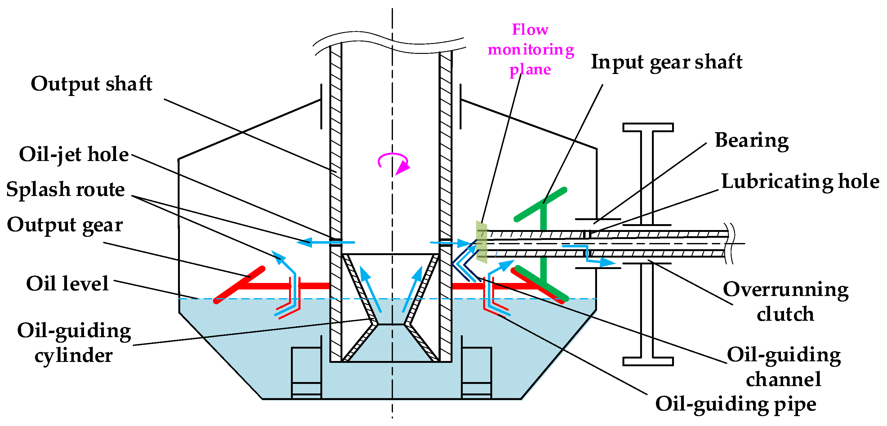
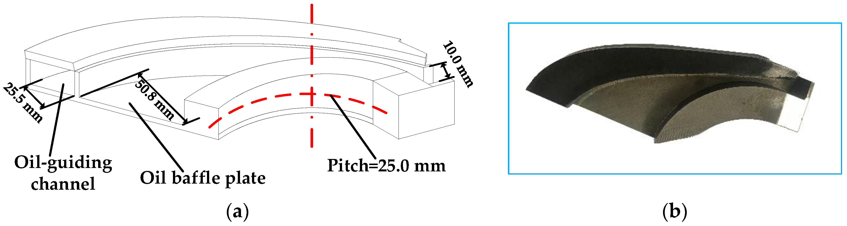
As depicted in Figure 1, large amounts of lubricating oil reach the driven gear surfaces pumped by the oil-guiding pipe; the role of the oil-guiding channel is to divert the oil to the driving shaft system for the lubrication of the bearings and clutch. The channel is a left-hand helix, and the diameters of the base circle and the pitch are 252 mm and 25 mm, respectively. The rounds are 0.5. The 3D model is shown in Figure 2. The channel can be divided roughly into two parts: the left part with a cover and the right part without a cover. The left part is to divert oil from the bevel gear surface to the main shaft to lubricate the bearings and clutch. The center of the other part is a section of a circle for concentric positioning with the driven shaft, and also the lubrication of the gear surface.
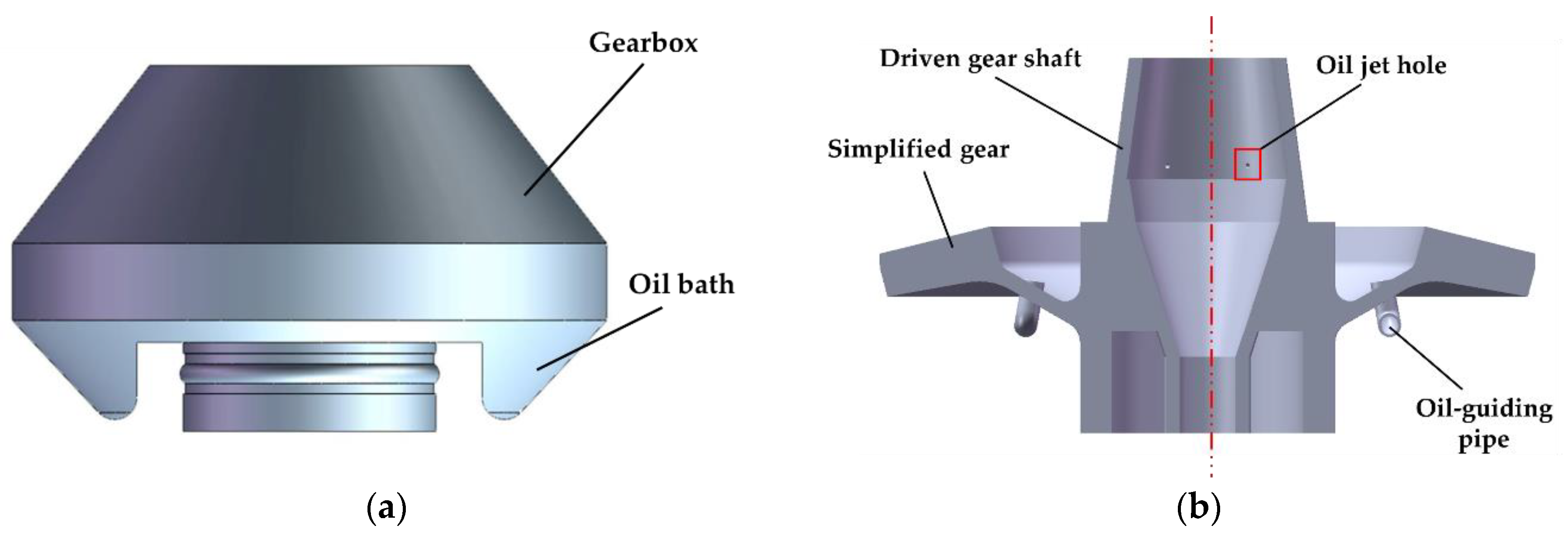
The flowchart of the CFD analysis, as listed in Figure 3, is implemented mainly through three phases: geometry simplification, model building, boundary conditions setting, and simulation calculation. The spiral bevel gears are not immersed in the oil bath; the conical surface is utilized instead of the tooth surfaces to cut down the calculated load. Meanwhile, the oil-guiding cylinder, oil-guiding pipe, driven gear shaft, and bearings are simplified and modeled as a part, as illustrated in Figure 4.
2.2.2. Flow-Monitoring Plane
To quantitate the lubricating oil flowing through the oil-guiding channel and evaluate the lubrication and cooling effect of the channel, a flow monitoring plane (x = 70 mm, yL = −15 mm, yH = 15 mm, zL = 105 mm, and zH = 135 mm) is defined at the outlet of the oil-guiding channel.
2.3. CFD Grid Technology
The calculation domain is divided into uniform hexahedral mesh types. A rectangular area of 274 mm × 274 mm × 135 mm is set up with a mesh quantity of 11,000,000 and a good mesh quality. In the calculation domain, a larger oil bath of 274 mm × 274 mm × 63 mm at rest is established as the fluid calculation domain to provide enough lubricating oil for the oil-guiding channel and pipes, as shown in Figure 5. The time-based output of this study is set with the restart data interval of 0.1 s. In the boundary condition setting, all six faces of the oil bath are set as symmetry boundaries. In this study, the pressure solver is implicitly solved. The convergence criterion is calculated automatically. In order to obtain faster computing speed and higher solution accuracy, the multiplier for the convergence criterion is set to 1, the maximum number of iteration failures is set to 25, and the GMRES subspace size is set to 15.
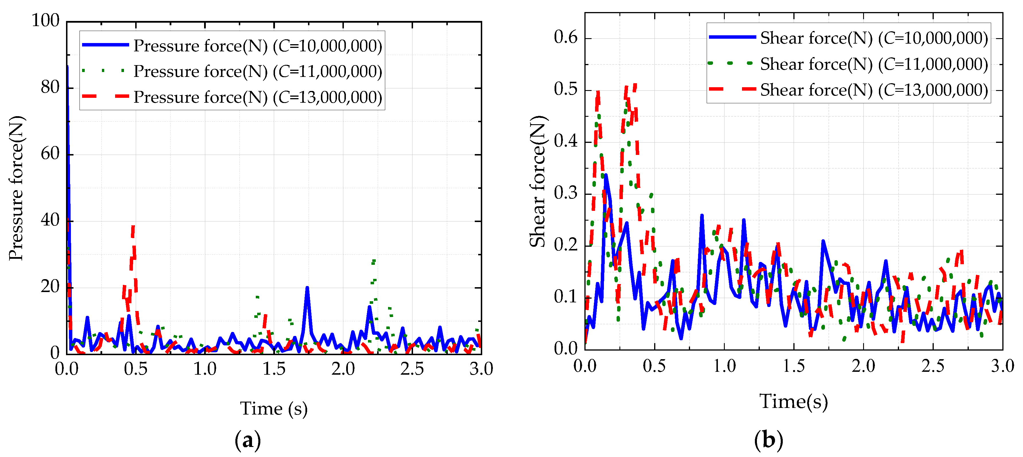
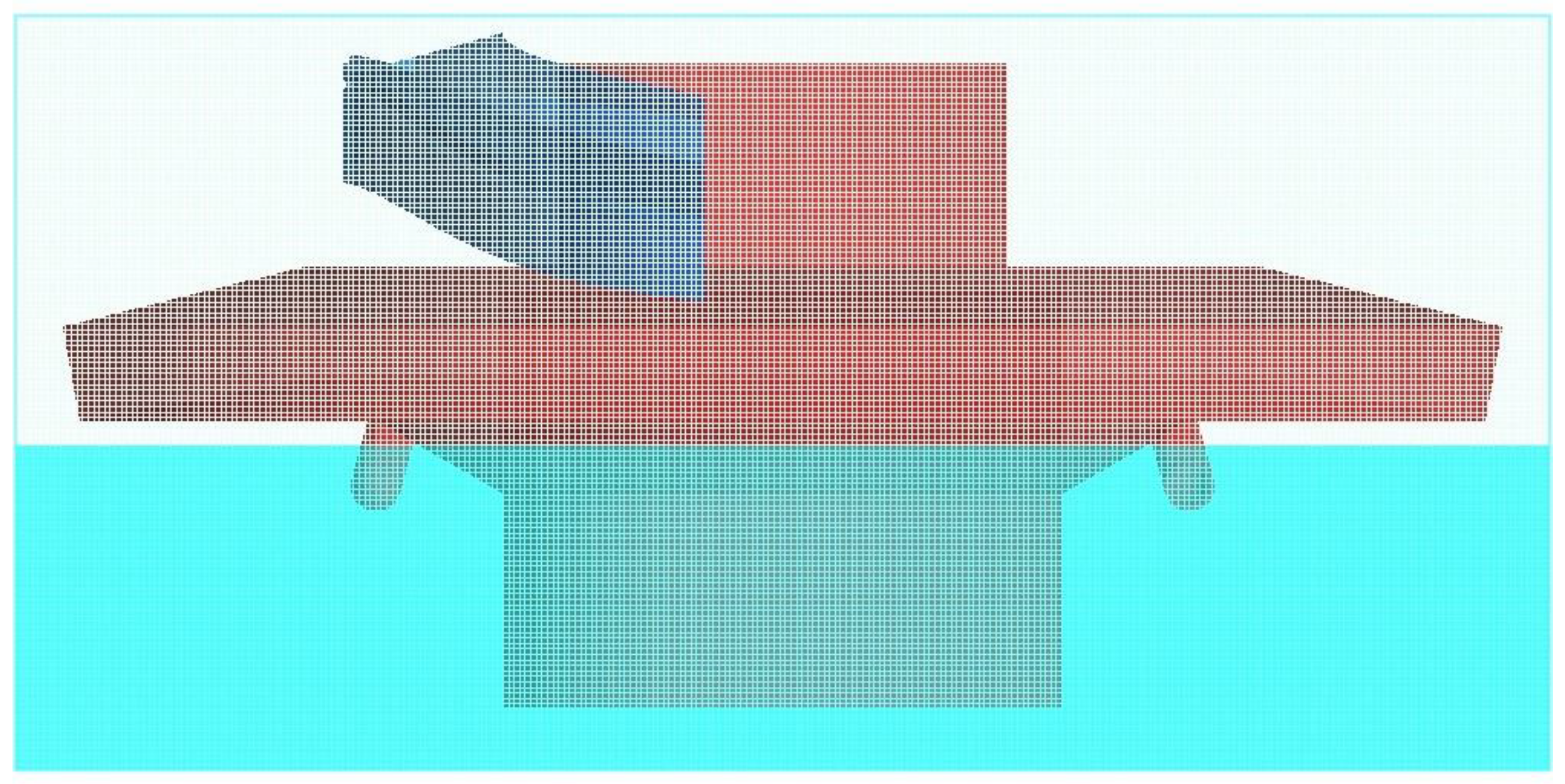
To ensure the accuracy of the CFD study, grid independence analysis is carried out. The total number of grids is set to 10 million, 11 million, and 13 million, respectively. The fluid pressure and shear force of the bevel gear and bearing components are used for grid independence analysis. Figure 6 depicts the numerical results with different grid numbers. As for Figure 6a,b, except for the initial fluctuation, the total number of grids has little effect on the pressure and shear force. Compared to the grid number of 10 million, the numerical results of the grid number of 11 million are closer to those of 13 million than those of 10 million. Balancing the calculated load and accuracy, the total number of the grid of this study is fixed to 11 million, as shown in Figure 7.
3. Numerical Results
This study mainly discusses the effects of typical operating conditions, including the effects of rotational speed and oil depth of the oil bath on the lubrication and cooling performance of the gear system together with the oil-guiding channel.
3.1. Rotating Speed
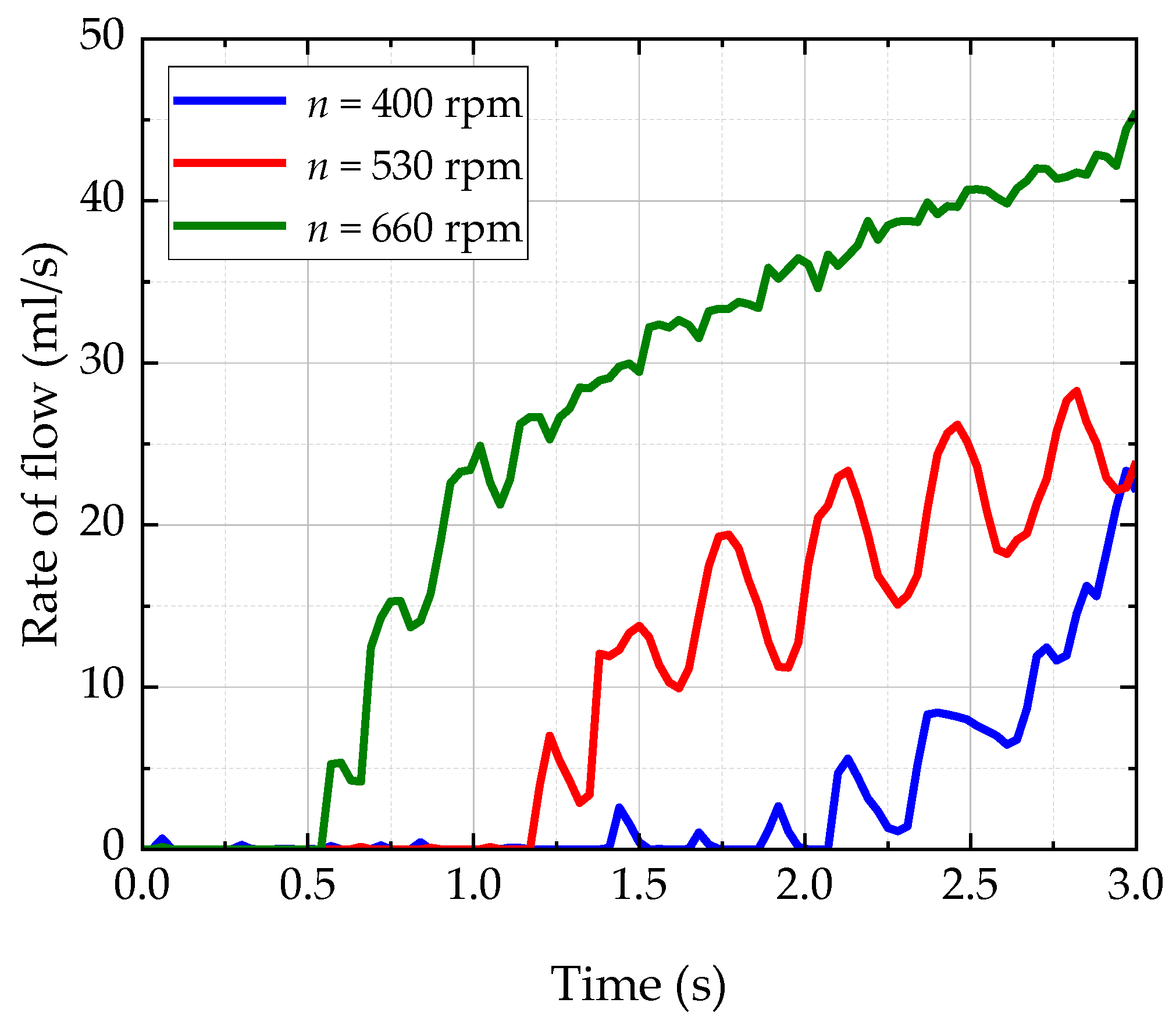
To quantify the influence of rotating speed on the oil-guiding channel, the rotating speed, n, of the driven gear shaft ranges from 400 rpm, to 530 rpm, to 660 rpm. The high oil depth of H = 68 mm is selected for the simulation analysis; the time traces of the flow rate passing through the monitoring surface under three different rotational speeds are given in Figure 8.
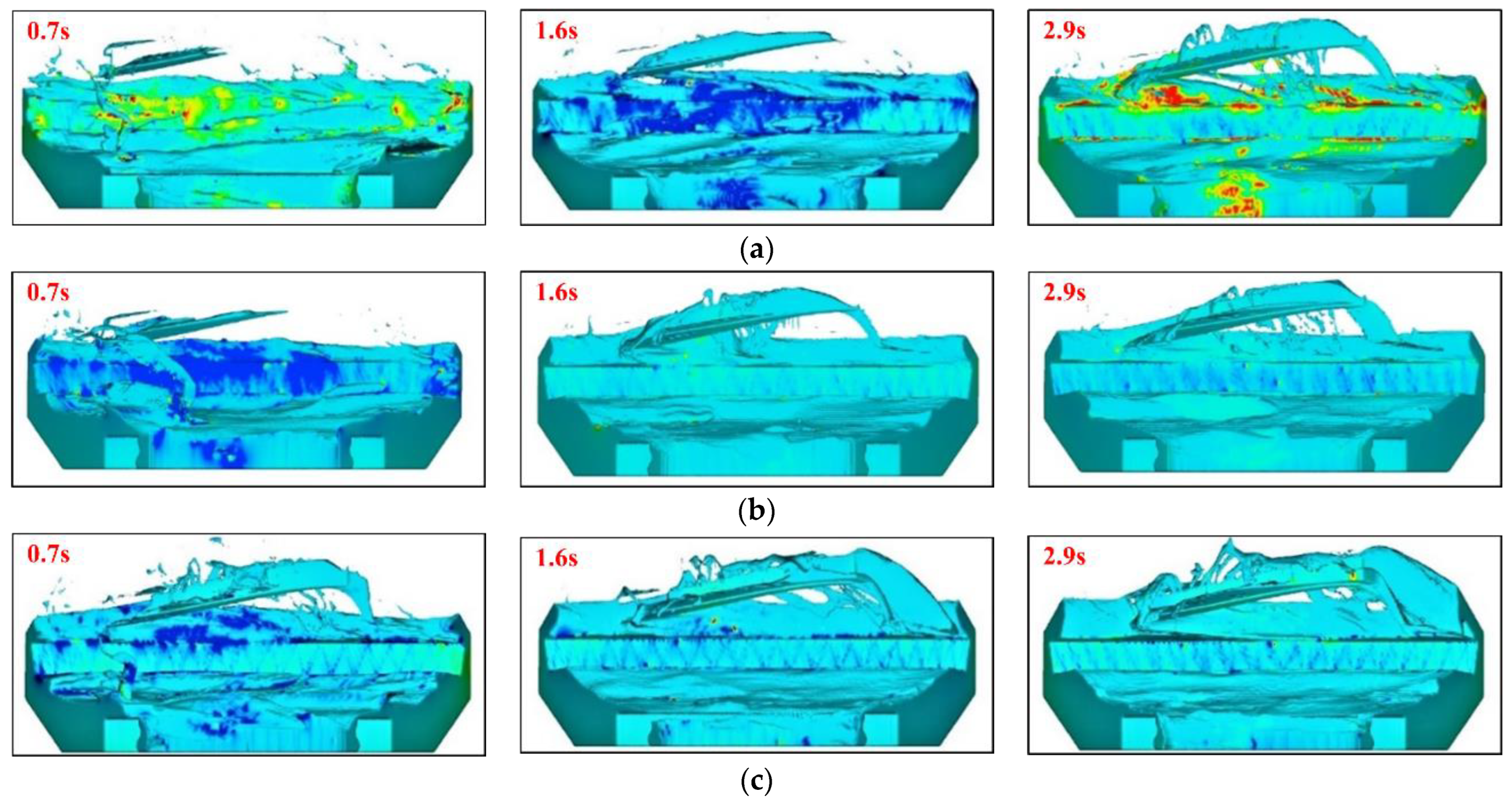
As can be seen from Figure 8, at 400 rpm, there is almost no oil through the monitoring plane until 2 s. By comparison, the oil is monitored at about 1.2 s for 530 rpm, and about 0.6 s for 660 rpm. This lag phenomenon of flow rate is associated with the time for the lubricant passing through the oil-guiding channel and reaching the monitoring plane at the oil outlet. It is also indicated that the higher the rotational speed is, the stronger the oil churning behavior is, and the greater the amount of oil reaching the monitoring plane. Figure 9 comes to a similar conclusion. Figure 9 plots the oil distribution at three different speeds, at three moments. At 0.7 s, 1.6 s, and 2.9 s, the oil in the oil-guiding channel at 660 rpm is significantly more than that at 400 rpm and 530 rpm. At 0.7 s, there is only a little oil in the oil-guiding channel at 400 rpm and 530 rpm, while the oil-guiding channel is full of lubricant at 630 rpm. That is, the higher the speed, the more violently the gears stirred the oil, the more violent the oil splashed, and then more oil entered the oil-guiding channel.
In addition, the increasing rate of the flow rate slows down and finally tends to be stable, especially for 530 rpm and 660 rpm. This is mainly due to the limited capacity of the oil bath in this numerical simulation. Furthermore, the average flow rates through the monitoring plane, calculated based on the total oil quantity and time through the monitoring surface, are shown in Table 1. The oil mass passing through the monitoring plane increases with the increase of the rotating speed under the same oil bath depth condition.
3.2. Oil Bath Depth
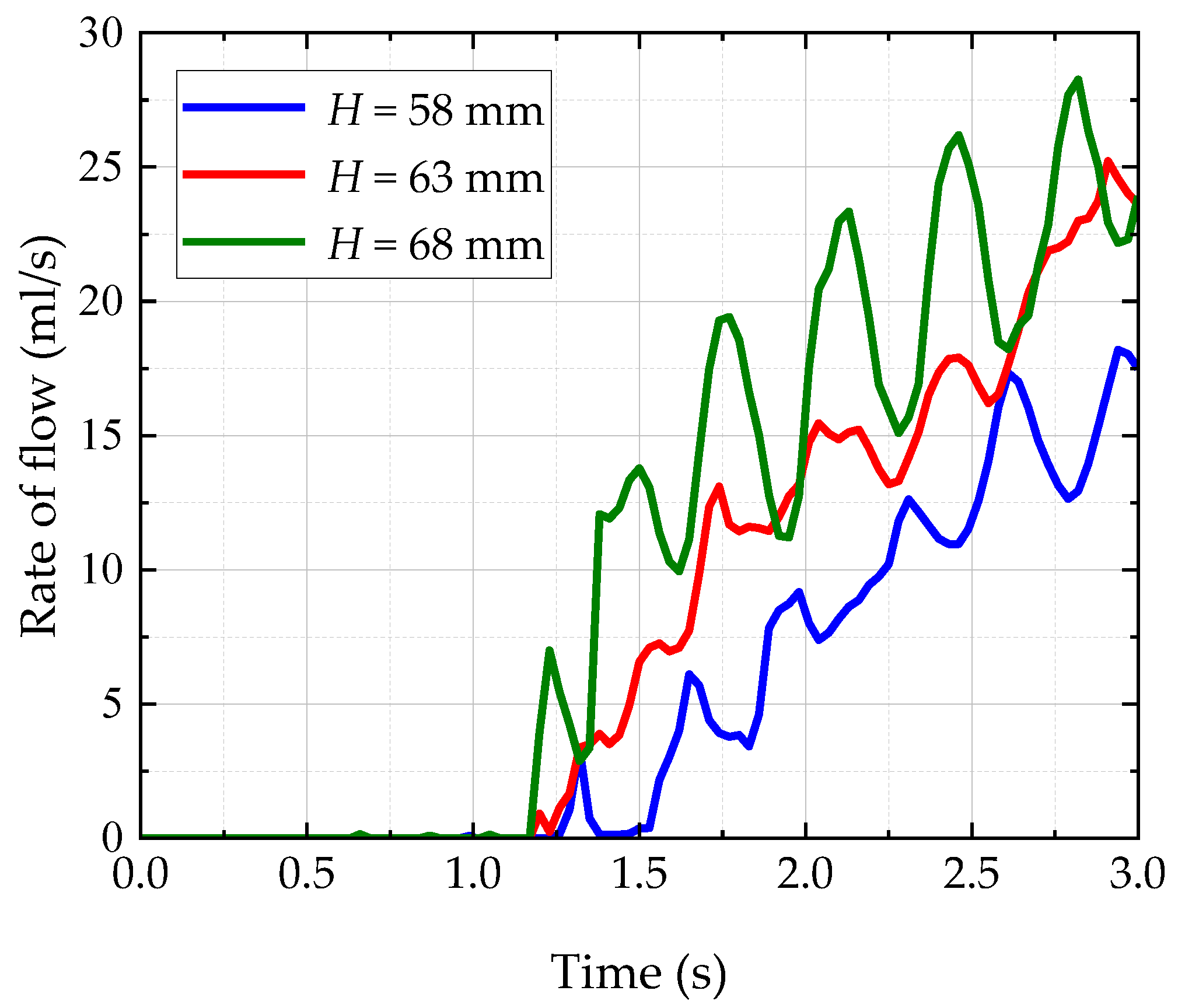
To quantify the influence of oil bath depth on the channel, the oil depth, H, is set to 58 mm, 63 mm, and 68 mm, and the rotational speed (n = 530 rpm) is preserved. The variation of the flow rate through the monitoring plane concerning the oil depth is shown in Figure 10. From this, the oil can be detected at about 1.3 s. In other words, the process of oil flowing through the oil-guiding pipes to the gear surfaces, and passing through the oil-guiding channel to the outlet, as illustrated in Figure 1, is closely related to the rotational speed, rather than the oil depth. It takes less time for the oil to reach the monitoring plane with greater kinetic energy under a higher speed condition. Figure 11 shows the oil distribution at three different oil depths at three moments. At 0.7 s, 1.6 s, and 2.9 s, the oil level at H = 68 mm has more oil in the oil-guiding channel than that at H = 58 mm and H = 63 mm, but the difference in oil volume is not significant compared to the different speed cases. It can be seen that the increase of both rotational speed and oil depth is beneficial to the lubricant entering the lubrication zone. However, comparing Figure 8 and Figure 11, the simple consensus is reached that the oil depth plays a relatively small role in the oil churning behavior, while the rotational speed is the most important influence factor.
In addition, the flow rate rises in the fluctuation under three different oil depths in Figure 10. The higher the oil depth is, the greater volatility of the flow rate. This suggests that the churning behavior of the oil-guiding pipes is stronger with a higher oil depth, resulting in a larger fluctuation. Clearly, the oil flowing through the monitoring plane is more when the oil bath is deeper. When the oil depth is 68 mm, the rate of flow increase is the greatest, and significantly higher than two other oil depths. The higher the oil depth, the higher the efficiency of the oil-guiding channel and the greater the flow rate reaching the monitoring plane. Furthermore, the average flow rates through the monitoring plane at different oil depths are calculated and listed in Table 2. It also gives the same result: at the same rotating speed, the deeper the oil bath, and the more oil reaches the driving gear.
4. Experimental Validation
To validate the validity of the above CFD method, the oil-guiding performance of the channel was tested on a specific test bench at various working conditions, including rotational speed and oil depth. The validity of the proposed CFD method is validated by comparing the captured numerical data and the measured experimental findings.
4.1. Test Bench
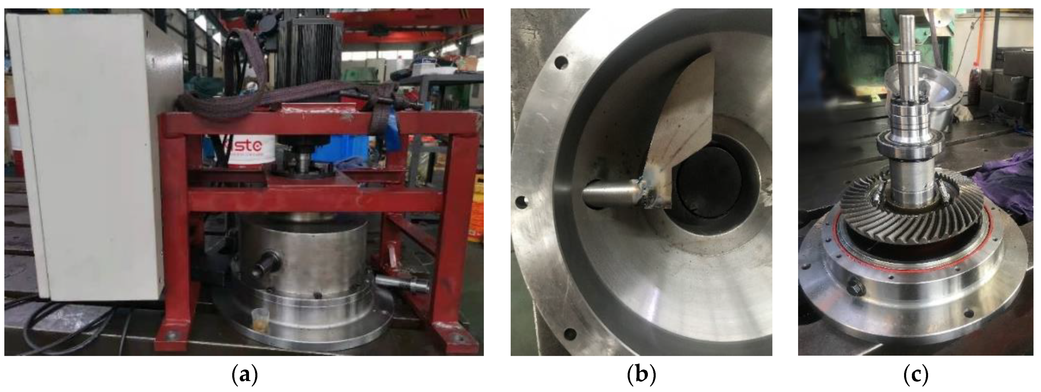
The test bench mainly includes a drive motor, a spiral bevel gear pair, a testing device, a test drive, and a control system. The test spiral bevel gear pair is driven by the motor through the coupling, and it is mounted on the hollow shaft through an interference fit. The removable oil-guiding pipes are installed on the gear wheel spoke; there is an oil drain hole on the wall of the hollow shaft above the oil-guiding pipes. One end of the oil-guiding channel is welded to the oil-collecting pipe, while the other end is overhung above the bevel gear with a distance of 3–5 mm to the gear surface for collecting the churned oil by the oil-guiding pipes. One end of the oil-collecting pipe is welded to the top of the oil-guiding channel, and the other end penetrates through the gearbox casing. The oil is quantitated with a glass measure cup placed below the oil-collecting pipe. The schematic diagram of the test devices is as shown in Figure 1, and the photos of the test bench, the oil-guiding channel, and the internal axle system are shown in Figure 12. Aeroshell turbine engine oil 555 is used in the experiments; its kinematic viscosity and dynamic viscosity are 26.62 mm2/s and 0.0233 kg/m/s, respectively, at 40 °C.
4.2. Experimental Findings
4.2.1. Rotating Speed
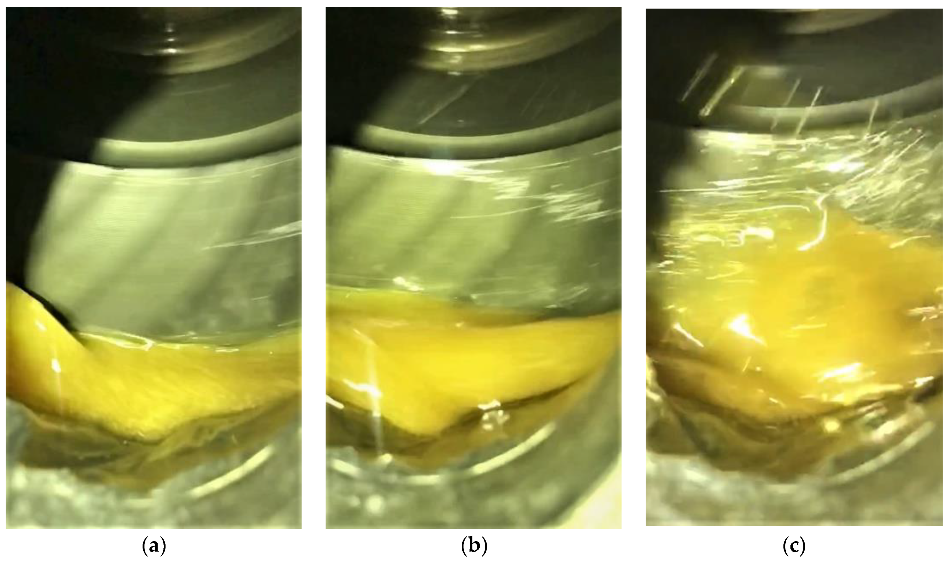
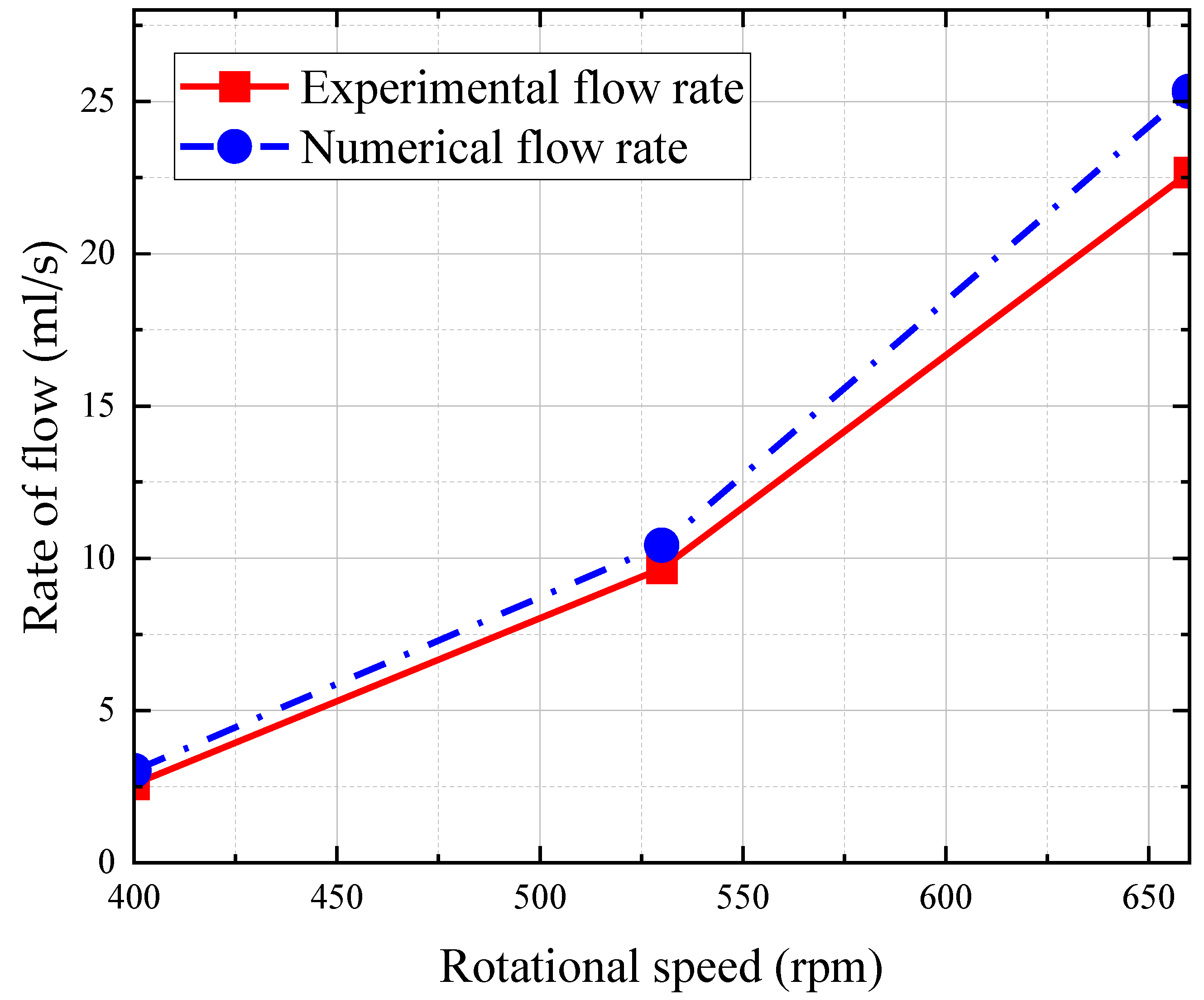
To observe the oil flow phenomenon, measure the flow rate in the experiments, and compare with the numerical results. The tests were carried out with the oil depth, H, of 68 mm; rotating speeds, n, of 400 rpm, 530 rpm, and 660 rpm, respectively; and each test was run for 3 min. The baseline tests were firstly performed at each rotational speed or oil depth without the oil-guiding channel in the gearbox. The pipe collected more lubricating oil passing through the oil-guiding channel at a higher speed, as described in connection with Figure 13. The measured flow rate and numerical values are listed in Table 3 and Figure 14. It can be seen that the churned lubricating oil is sensitive to the rotational speed. That is, the increase in speed helps to increase the lubricating oil in the oil-jet hole.
Meanwhile, the amount of oil transferred from the gear surface to the oil-guiding channel increases, owing to the oil-guiding channel, and the flow rate grows significantly under three different speeds. The relative errors between the average experimental and the numerical flow rate are 14.7%, 7.3%, and 10.5% at the rotating speeds of 400 rpm, 530 rpm, and 660 rpm. At low speeds, the error is relatively large; this is caused by the difference between the simplified calculated model and the physical system. Even so, the experimental results agree well with the numerical values, which verifies that the proposed CFD method is valid.
4.2.2. Oil Bath Depth
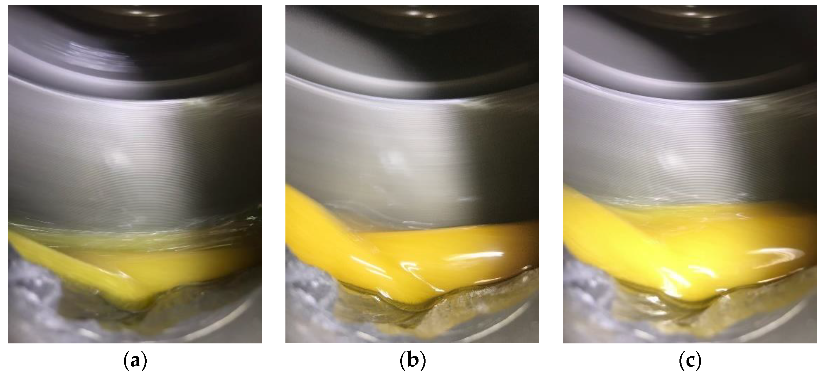
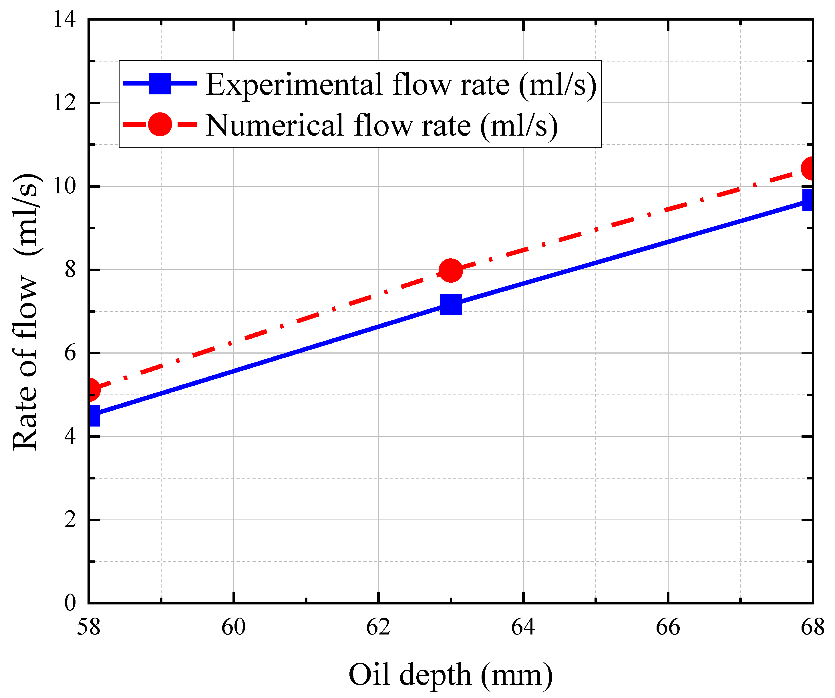
To compare the numerical analysis with different oil depths, the rotating speed of 530 rpm remained unchanged, and the oil depth was set to 58 mm, 63 mm, and 68 mm, corresponding to low, medium, and high oil depths, for lubrication tests. The running time of each test was also 3 min. The oil churning phenomenon becomes slightly obvious with the increase of the oil depth, as depicted in Figure 15, while the churning behavior is more intense with the increasing rotating speed. The comparison of experimental and numerical flow rates is listed in Table 4 and Figure 16. The flow rate passing through the monitoring plane increases as the oil depth rises, whether in experimental data or numerical value. The oil is churned violently by the spinning gear; therefore, a higher oil depth drives more oil from the tooth surface to reach the oil-guiding channel and reaches the oil-collecting pipe. Of course, the increased oil depth also increases the flow rate in the baseline tests. Nevertheless, the relative errors between the experimental net flow rate and the numerical flow rate are 12.1%, 12.4%, and 7.3%, at oil depths of 58 mm, 63 mm, and 68 mm.
Again, the experimental findings show a good agreement with the numerical values. These experiments and the numerical analysis suggest that the increase in rotational speed or oil depth can increase the amount of splashed oil, and grow the flow rate.
5. Conclusions
This study introduces the oil-guiding channel to improve the performance of the oil-guiding splash lubrication method utilized in the main gearbox of light helicopters. The effect of the oil-leading hood on the lubrication and cooling effect under different rotational speeds and oil depths is numerically analyzed. Furthermore, lubrication tests were performed on a specific test bench under different working conditions. The relative errors between experiments and numerical analysis are no more than 15% and less than 13% for most cases. Some conclusions are as follows:
- By leveraging the oil-guiding channel, the oil mass transferred from the gear surface into the channel increases, and then the oil volume collected through the oil-collecting pipe also increases. Specifically, at the rotating speed of 400 rpm, the oil flow rate with the oil-guiding channel in this study exceeds 2.5 mL/s, far more than the experimental data of 0.0017 mL/s, conducted by Yin et al. [27,28]. At the rotating speed of 660 rpm, the oil flow rate with the oil-guiding channel exceeds 22.6 mL/s, much greater than the experimental data of 0.034 mL/s, performed by Yin et al. [27,28]. This shows the oil flow rate is increased by about three orders of magnitude, benefiting from the oil-guiding channel. Therefore, the oil-leading hood can effectively increase the flow rate and improve the lubrication efficiency of the whole lubrication system.
- The flow rate of the oil reaching the oil-jet hole increases with the increase of rotational speed. Increasing the rotational speed, the oil volume through the oil-guiding pipe grows and the splash of oil is stronger. The pipe collects more lubricating oil that passes through the oil-guiding channel, and the increasing rotational speed contributes to the increase of the oil mass, to reach the driving gear.
- The flow rate reaching the oil-jet hole increases with the increase of oil depth. When the depth of the oil bath is raised, the oil is churned violently by the spinning gear. So, a deeper oil bath contributes to more oil flowing through the oil-guiding pipe, into the oil-guiding channel. However, too high an oil depth, causing the spiral bevel gear to be immersed in the oil bath, will bring a significant churning power loss.
Future work is under way to explore the influences of the geometry parameters of the oil-guiding channel. The oil temperature and flight inclination are also considered to be more approximate to the reality of numerical and experimental analysis.
Author Contributions
Conceptualization, Y.D. and D.Y.; methodology, L.X.; software, X.C.; validation, L.X., D.Y. and X.Z.; formal analysis, L.X.; investigation, D.Y.; resources, Y.D.; data curation, X.C. and L.X.; writing—original draft preparation, X.Z.; writing—review and editing, X.C.; visualization, X.Z.; supervision, X.Z. and Y.D.; project administration, Y.D.; funding acquisition, Y.D. All authors have read and agreed to the published version of the manuscript.
Funding
This research was funded by the National Defense Preliminary Research Project of China (Grant No. KY-1044-2020-0657).
Institutional Review Board Statement
Not applicable.
Informed Consent Statement
Not applicable.
Data Availability Statement
Data is contained within the article.
Acknowledgments
We would like to express our thanks to the editors of Lubricants and the anony-mous reviewers for their work in processing this article.
Conflicts of Interest
The authors declare no conflict of interest.
References
- Concli, F.; Della Torre, A.; Gorla, C.; Montenegro, G. A new integrated approach for the prediction of the load independent power losses of gears: Development of a mesh-handling algorithm to reduce the CFD simulation time. Adv. Tribol. 2016, 2016, 1–8. [Google Scholar] [CrossRef]
- Concli, F.; Gorla, C. Numerical modeling of the power losses in geared transmissions: Windage, churning and cavitation simulations with a new integrated approach that drastically reduces the computational effort. Tribol. Int. 2016, 103, 58–68. [Google Scholar] [CrossRef]
- Concli, F.; Gorla, C. Numerical modeling of the churning power losses in planetary gearboxes: An innovative partitioning-based meshing methodology for the application of a computational effort reduction strategy to complex gearbox configurations. Lubr. Sci. 2017, 29, 455–474. [Google Scholar] [CrossRef]
- Liu, H.; Jurkschat, T.; Lohner, T.; Stahl, K. Determination of oil distribution and churning power loss of gearboxes by finite volume CFD method. Tribol. Int. 2017, 109, 346–354. [Google Scholar] [CrossRef]
- Liu, H.; Jurkschat, T.; Lohner, T.; Stahl, K. Detailed investigations on the oil flow in dip-lubricated gearboxes by the finite volume CFD method. Lubricants 2018, 6, 47. [Google Scholar] [CrossRef] [Green Version]
- Liu, H.; Arfaoui, G.; Stanic, M.; Montigny, L.; Jurkschat, T.; Lohner, T.; Stahl, K. Numerical modelling of oil distribution and churning gear power losses of gearboxes by smoothed particle hydrodynamics. Proc. Inst. Mech. Eng. Part J. Eng. Tribol. 2019, 233, 74–86. [Google Scholar] [CrossRef]
- Gong, R.; Gong, Q.; Che, H.; Zhang, Z. Numerical investigation on churning loss torque and oil distribution of reducer based on lattice boltzmann method. Tribol. Trans. 2021, 64, 968–979. [Google Scholar] [CrossRef]
- Hu, X.; Jiang, Y.; Luo, C.; Feng, L.; Dai, Y. Churning power losses of a gearbox with spiral bevel geared transmission. Tribol. Int. 2019, 129, 398–406. [Google Scholar] [CrossRef]
- Hu, X.; Wang, A.; Li, P.; Wang, J. Influence of dynamic attitudes on oil supply for bearings and churning power losses in a splash lubricated spiral bevel gearbox. Tribol. Trans. 2021, 159, 106951. [Google Scholar] [CrossRef]
- Jiang, Y.; Hu, X.; Hong, S.; Li, P.; Wu, M. Influences of an oil guide device on splash lubrication performance in a spiral bevel gearbox. Tribol. Trans. 2019, 136, 155–164. [Google Scholar] [CrossRef]
- Lu, F.; Wang, M.; Bao, H.; Huang, W.; Zhu, R. Churning power loss of the intermediate gearbox in a helicopter under splash lubrication. Proc. Inst. Mech. Eng. Part J J. Eng. Tribol. 2022, 236, 49–58. [Google Scholar] [CrossRef]
- Legrady, B.; Taesch, M.; Tschirschnitz, G.; Mieth, C.F. Prediction of churning losses in an industrial gear box with spiral bevel gears using the smoothed particle hydrodynamic method. Forsch. Im Ing. 2021, 1–10. [Google Scholar] [CrossRef]
- Wang, Y.; Song, G.; Niu, W.; Chen, Y. Optimized design of spray parameters of oil jet lubricated spur gears. Tribol. Trans. 2018, 120, 149–158. [Google Scholar] [CrossRef]
- Wang, Y.; Song, G.; Niu, W.; Chen, Y. Influence of oil injection methods on the lubrication process of high speed spur gears. Tribol. T. 2018, 121, 180–189. [Google Scholar] [CrossRef]
- Dai, Y.; Ma, F.; Zhu, X.; Su, Q.; Hu, X. Evaluation and optimization of the oil jet lubrication performance for orthogonal face gear drive: Modelling, simulation and experimental validation. Energies 2019, 12, 1935. [Google Scholar] [CrossRef] [Green Version]
- Ouyang, B.; Ma, F.; Dai, Y.; Zhang, Y. Numerical analysis on heat-flow-coupled temperature field for orthogonal face gears with oil–jet lubrication. Eng. Appl. Comp. Fluid 2021, 15, 762–780. [Google Scholar] [CrossRef]
- Zhu, X.; Dai, Y.; Ma, F.; Ouyang, B. Mathematical modeling and numerical simulation for determining an optimized oil jet layout for spiral bevel gear lubrication. Proc. Inst. Mech. Eng. Part J J. Eng. Tribol. 2021, 235, 611–628. [Google Scholar] [CrossRef]
- Massini, D.; Fondelli, T.; Facchini, B.; Tarchi, L.; Leonardi, F. High speed visualizations of oil jet lubrication for aero-engine gearboxes. Energy Procedia 2016, 101, 1248–1255. [Google Scholar] [CrossRef]
- Fondelli, T.; Andreini, A.; Da Soghe, R.; Facchini, B.; Cipolla, L. Numerical simulation of oil jet lubrication for high speed gears. Int. J. Aerosp. Eng. 2015, 2015. [Google Scholar] [CrossRef]
- Massini, D.; Fondelli, T.; Facchini, B.; Tarchi, L.; Leonardi, F. Experimental investigation on power losses due to oil jet lubrication in high speed gearing systems. In Turbo Expo: Power for Land, Sea, and Air; American Society of Mechanical Engineers: New York, NY, USA, 2017; Volume 50886, p. V05BT15A030. [Google Scholar] [CrossRef]
- Keller, M.C.; Braun, S.; Wieth, L.; Chaussonnet, G.; Dauch, T.; Koch, R.; Bauer, H.J. Numerical modeling of oil-jet lubrication for spur gears using smoothed particle hydrodynamics. In Proceedings of the 11th International SPHERIC Workshop, Munich, Germany, 14–16 June 2016; pp. 69–76. [Google Scholar]
- Keller, M.C.; Braun, S.; Wieth, L.; Chaussonnet, G.; Dauch, T.F.; Koch, R.; Bauer, H.J. Smoothed particle hydrodynamics simulation of oil-jet gear interaction1. J. Tribol. ASME 2019, 141, 071703. [Google Scholar] [CrossRef]
- Keller, M.C.; Kromer, C.; Cordes, L.; Schwitzke, C.; Bauer, H.J. CFD study of oil-jet gear interaction flow phenomena in spur gears. Aeronaut. J. 2020, 124, 1301–1317. [Google Scholar] [CrossRef]
- Ambrose, S.; Morvan, H.; Simmons, K. Investigation of oil jet impingement on a rotating gear using lattice boltzman method (LBM). In Turbo Expo: Power for Land, Sea, and Air; American Society of Mechanical Engineers: New York, NY, USA, 2018; Volume 50985, p. V001T01A028. [Google Scholar] [CrossRef]
- Dai, Y.; Liang, C.; Chen, X.; Zhu, X. Numerical analysis for wetting behaviors of an oil jet lubricated spur gear. Lubricants 2022, 10, 17. [Google Scholar] [CrossRef]
- Kromer, C.; von Plehwe, F.C.; Keller, M.C.; Schwitzke, C.; Bauer, H.J. Analytical model for the heat transfer in impingement cooled spur gears. In Turbo Expo: Power for Land, Sea, and Air; American Society of Mechanical Engineers: New York, NY, USA, 2020; Volume 84058, p. V001T01A023. [Google Scholar] [CrossRef]
- Yin, M.; Xu, L.J.; Dai, Y.; Yang, D.; Zhu, X. Flow characteristics of oil-guiding splash lubrication: Simulation and experiment studies. Int. J. Simul. Model. 2021, 20, 363–374. [Google Scholar] [CrossRef]
- Yin, M.; Chen, X.; Dai, Y.; Yang, D.; Xu, L.; Zhu, X. Numerical and experimental investigation of oil-guiding splash lubrication in light helicopter’s reducers. Aerospace 2021, 8, 345. [Google Scholar] [CrossRef]
Figure 1.
Schematic diagram of the oil-guiding splash lubrication system in light helicopters.

Figure 2.
Oil-guiding channel: (a) schematic diagram; (b) photo.

Figure 3.
Flowchart of the flow problem.

Figure 4.
Simplified Models: (a) gearbox and bearings; (b) simplified driven gear and oil-guiding pipes.
Figure 4.
Simplified Models: (a) gearbox and bearings; (b) simplified driven gear and oil-guiding pipes.

Figure 5.
Simulation model of simplified driven gear with oil bath at rest.

Figure 6.
Pressure and shear force versus time with the different total number of grids. (a) Pressure force on the gear; (b) shear force on the bearings.
Figure 6.
Pressure and shear force versus time with the different total number of grids. (a) Pressure force on the gear; (b) shear force on the bearings.

Figure 7.
Fluid elements of simplified driven gear with oil bath at rest.

Figure 8.
Time trace of flow rate at a different rotational speed.

Figure 9.
Cross-section of flow field characteristic distribution: (a) 400 rpm; (b) 530 rpm; (c) 660 rpm.
Figure 9.
Cross-section of flow field characteristic distribution: (a) 400 rpm; (b) 530 rpm; (c) 660 rpm.

Figure 10.
Time trace of flow rate at the different oil depths.

Figure 11.
Cross-section of flow field characteristic distribution: (a) H = 58 mm; (b) H = 63 mm; (c) H = 68 mm.
Figure 11.
Cross-section of flow field characteristic distribution: (a) H = 58 mm; (b) H = 63 mm; (c) H = 68 mm.

Figure 12.
Oil-guiding splash lubrication test bench: (a) whole system; (b) oil-guiding channel; (c) internal axle system.
Figure 12.
Oil-guiding splash lubrication test bench: (a) whole system; (b) oil-guiding channel; (c) internal axle system.

Figure 13.
Oil distribution of experiments: (a) n = 400 rpm; (b) n = 530 rpm; (c) n = 630 rpm.

Figure 14.
Flow rate versus rotational speed.

Figure 15.
Oil distribution of experiments: (a) H = 58 mm; (b) H = 63 mm; (c) H = 68 mm.

Figure 16.
Flow rate versus oil depth.


Table 1.
Numerical average oil flow rate against rotational speed.
| Rotational Speed n (rpm) | Running Time (s) | Numerical Average Oil Flow Rate (mL/s) |
|---|---|---|
| 400 | 3 | 3.029 |
| 530 | 3 | 10.427 |
| 660 | 3 | 25.332 |
Table 2.
Numerical averaged flow rate against oil depth.
| Oil Depth H (mm) | Running Time (s) | Numerical Average Oil Flow Rate (mL/s) |
|---|---|---|
| 58 | 3 | 5.119 |
| 63 | 3 | 8.177 |
| 68 | 3 | 10.427 |
Table 3.
Experimental and numerical flow rate under different rotational speeds.
| Rotational Speed n (rpm) | Running Time (min) | Experimental Flow Rate (mL/s) | Baseline Testing Flow Rate (mL/s) | Numerical Flow Rate (mL/s) | Relative Error |
|---|---|---|---|---|---|
| 400 | 3 | 2.583 | 0.058 | 3.029 | 14.7% |
| 530 | 3 | 9.667 | 0.528 | 10.427 | 7.3% |
| 660 | 3 | 22.667 | 0.556 | 25.332 | 10.5% |
Table 4.
Experimental and numerical average flow rate with different oil depth.
| Oil Depth H (mm) | Running Time (min) | Experimental Flow Rate (mL/s) | Baseline Testing Flow Rate (mL/s) | Numerical Flow Rate (mL/s) | Relative Error |
|---|---|---|---|---|---|
| 58 | 3 | 4.500 | 0.333 | 5.119 | 12.1% |
| 63 | 3 | 7.167 | 0.417 | 8.177 | 12.4% |
| 68 | 3 | 9.667 | 0.528 | 10.427 | 7.3% |
Publisher’s Note: MDPI stays neutral with regard to jurisdictional claims in published maps and institutional affiliations. |
© 2022 by the authors. Licensee MDPI, Basel, Switzerland. This article is an open access article distributed under the terms and conditions of the Creative Commons Attribution (CC BY) license (https://creativecommons.org/licenses/by/4.0/).
Share and Cite
MDPI and ACS Style
Dai, Y.; Chen, X.; Yang, D.; Xu, L.; Zhu, X. Performance of a New Aeronautic Oil-Guiding Splash Lubrication System. Lubricants 2022, 10, 130. https://0-doi-org.brum.beds.ac.uk/10.3390/lubricants10060130
AMA Style
Dai Y, Chen X, Yang D, Xu L, Zhu X. Performance of a New Aeronautic Oil-Guiding Splash Lubrication System. Lubricants. 2022; 10(6):130. https://0-doi-org.brum.beds.ac.uk/10.3390/lubricants10060130
Chicago/Turabian StyleDai, Yu, Xi Chen, Duan Yang, Lanjin Xu, and Xiang Zhu. 2022. "Performance of a New Aeronautic Oil-Guiding Splash Lubrication System" Lubricants 10, no. 6: 130. https://0-doi-org.brum.beds.ac.uk/10.3390/lubricants10060130
Note that from the first issue of 2016, this journal uses article numbers instead of page numbers. See further details here.