CERES Gimbal Performance on Terra

Consultant, 511 Cameo Drive, Hampton, VA 23666, USA
Lubricants 2020, 8(8), 79; https://0-doi-org.brum.beds.ac.uk/10.3390/lubricants8080079
Submission received: 26 May 2020
/
Revised: 19 July 2020
/
Accepted: 21 July 2020
/
Published: 27 July 2020
(This article belongs to the Special Issue Tribology of Space Mechanisms)
Abstract
:The Terra satellite has been operating in orbit for 20 years. The Terra satellite is also called the flagship earth-observing satellite. The two Clouds and the Earth’s Radiant Energy System CERES instruments on board continue to function nominally. Their expected mission lifetime was 7 years. Critical to their performance is the longevity of the scanning gimbals. This can be traced to the performance of the fluid-lubricated bearings. Two metrics are used to estimate their lifetime and health. Both lend themselves to readily available data and ease of interpretation. One is predicting the evaporative lubricant loss. This analysis indicates that the lubricant supply is adequate for the continual life of the gimbals. The second is trending the torque with time. Torque precursors are sampled quarterly. These data are converted to torque. Two types of torque behavior were examined. Contrasting torque data have supported the conclusion that the gimbals are operating nominally. This can be partially attributed to the design choices for the bearings and lubricant. The aim of this paper is to quantitatively describe the present health and expected life of the CERES gimbals on the Terra satellite.

1. Introduction
1.1. Instrument and Gimbal Background
The Terra satellite (EOS-AM-1) was launched in December 1999. Mission operations began in February 2000. Prior to launch, the expected space mission lifetime was 5 years. Two CERES instrument Flight Models (FM1 and FM2) are flown on Terra. The CERES instruments were designed and assembled with 1990s technology. The gimbals on the CERES Flight models are functioning nominally. The CERES instruments collect data related to the energy exchange between the Sun, the Earth’s atmosphere, clouds, surface, and space.
The aim of this project is to interpret data on the CERES instruments’ gimbals. We also use these data to update their calculated lifetimes and trend the most likely causes/sources of failure/degradation. This is accomplished using inflight data-based torque and calculating evaporative lubricant loss with flight time.
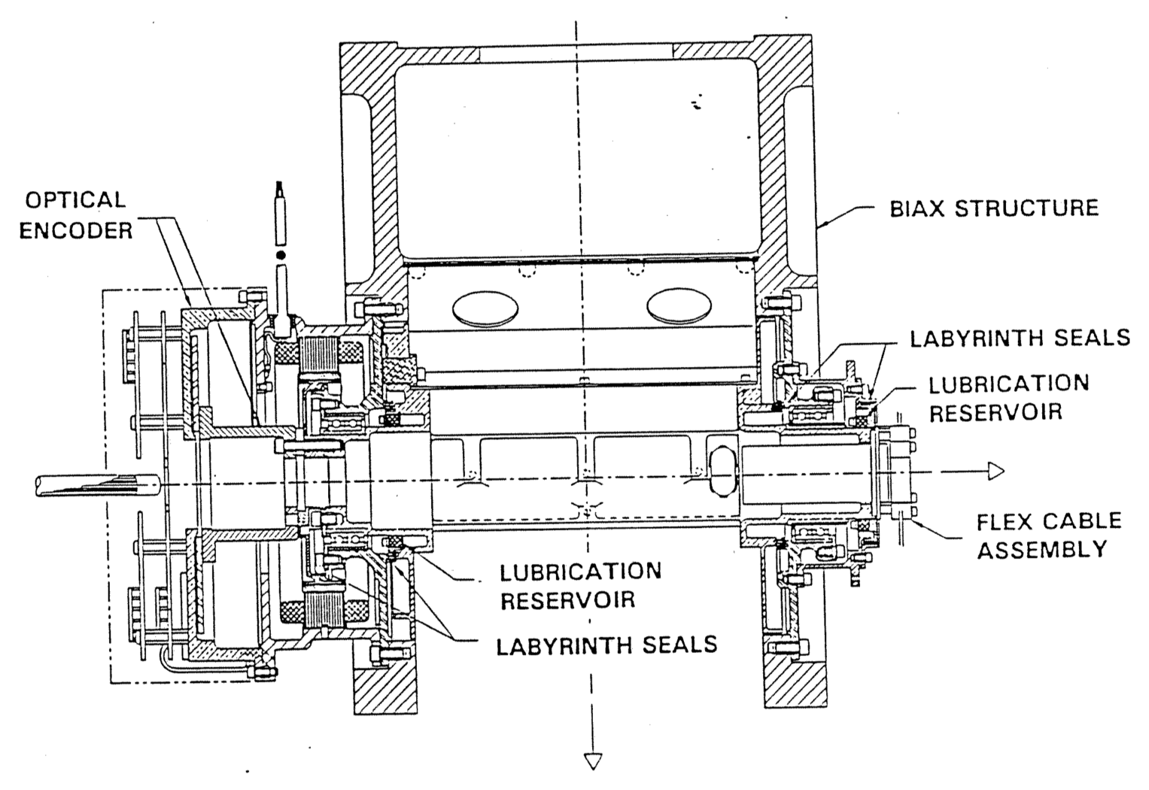
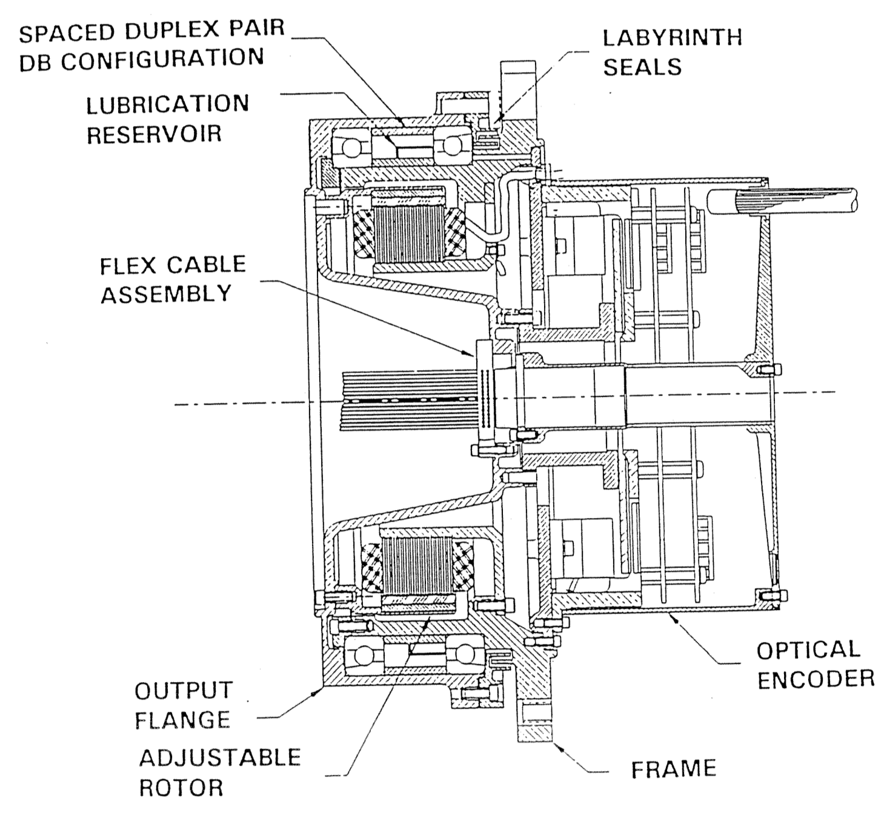
Each CERES instrument scan assembly has five electromechanical drives. These are elevation scan, azimuth scan, main cover, mirror attenuator mosaic door, and azimuth brake (DRL-70). The last three drives listed are not a matter of concern for current operations. These drives served to protect instrument detectors and bearings during spacecraft launch and commissioning and are no longer used. The two active drives in this study are the elevation scanner (Figure 1) and the azimuth scanner (Figure 2). The elevation scanner assembly supports three sensors between two sets of bearings. The azimuth scanner assembly contains one set of bearings. The bearings are sealed from the outside to contain lubricating oil. This is accomplished by a non-contacting labyrinth seal. The labyrinth seal consists of narrow interlocking grooves with appropriate ordered clearances. The labyrinth seal, or controlled leakage seal, allows lubricant to enter the bearings [1]. The labyrinth seal geometry and dimensions have a direct impact on lubricant loss [2].
CERES gimbals employ a passive lubricant system. This is also called a continuous lubricant system. Here, lubricant is continuously fed to the bearings at a controlled rate [3]. The lubricant reservoirs are micro-wells (polypropylene). All of the bearings have one-piece phenolic retainer/separators.
The four defined regimes of lubrication are deduced from the Stribeck–Hersey curve. The dependent axis is the coefficient of friction. This independent, dimensionless axis is the product of the lubricant viscosity and relative velocity and is inversely proportional to ball load. For the CERES gimbals, boundary lubrication is desired. Here, lubrication depends on the adhesion of lubricant molecules to counter-face surfaces. There are additional factors that can influence boundary lubrication. This renders its understanding complex [4].
The gimbals and associated bearings are within the low-speed regime (rotational rate). The scanning behavior of both gimbals is oscillatory. This is in contrast to continuously rotating gimbals. Elevation gimbal scans have the most useful data because of their near-constant operation. However, quarterly gimbal diagnostic scanning is performed to assess the gimbal status of both the azimuth and elevation gimbals. Two types of data used in evaluating gimbal health are torque and position error. For CERES, torque can be derived from position error data. Gimbal health is also related to initial lubricants and lubricant loss rate.
It is assumed that operation will be in a near vacuum. This is appropriate for operation in space. On CERES gimbals, the bearing material is 1AISI 440C steel. This is a common material for space scanner-bearing applications [5]. The bearing unit components are made of the same material. This is to minimize thermal stress effects [6].
Bearing sets are located at two locations on the elevation gimbal. These are fixed and compensating. Both types of elevation bearings have a contact angle between 15–20°. They both have a phenolic (one piece) retainer. All retainers were fully impregnated with lubricant at assembly. There is only one set of bearings on the azimuth gimbal. The contact angle is 30 deg with a phenolic three-piece retainer [7].
The properties of the CERES gimbals can be found in Table 1.
1.2. Space Lubricant
Space missions like Terra have longer expected lifetimes and often exceed expected lifetimes. This places more burden on the lubricant system. Lubricant levels also influence torque behavior. Too much lubricant can lead to excessive torque values. Too little lubricant can result in excessive values of bearing torque.
Gimbal failure can be attributed to lubricant loss or lubricant decomposition [8]. A CERES elevation gimbal underwent ground testing. Upon its conclusion, the lubricant was inspected. There was no evidence of decomposition [7]. Wear is also not a source of space gimbal failure. Not all loss mechanisms are easily quantifiable. This document focusses on evaporative lubricant loss.
Typical space lubricants can be of three classes: liquid, solid, or grease. CERES-qualified lubricants should have or balance the following qualities: low vapor pressure, wide operating temperature range (within expected operating temperatures), good boundary lubrication, and low consumption. Lubrication loss rate is proportional to vapor pressure.
There were several lubricant options at the time of the CERES Terra gimbal assembly. Multiply alkylated cyclopentane (MAC) liquid lubricants best met the complex metrics for lubricating CERES gimbal bearings. MACs exhibit excellent vapor pressure characteristics. A MAC liquid with medium viscosity is Pennzane 2000. It also exhibits a moderately cold temperature performance.
Trade studies were undertaken before and after gimbal assembly. Semi-quantitative comparisons show that liquid MAC lubricants lasted longer than perfluoropolyether lubricants (PFPE) [9,10,11,12,13,14]. PFPEs cannot accept anti-wear additives.
For CERES Terra, MT7-5-4 lubrication is used on all ball bearings and drives. MT7-5-4 was/is a mixture of Pennzane 2000 with additives. Studies have shown that adding additives to Pennzane 2001 significantly reduced its wear rate [9,15].
Additives should have volatility comparable to Pennzane. They should also be present in a minimum concentration [15]. These additives are lead napthenate (an anti-wear additive <2%) and an anti-oxidant, <1%. Anti-oxidation additives prevent lubricant degradation from oxygen exposure while in storage [16].
This is a typical combination for the enhanced boundary regime lubrication of space-based gimbals. MT7-5-4 exhibited minimum wear, the lowest vapor pressure, and the lowest loss of lubricant. It can also eliminate the presence of free ester impurity. This presence of this impurity was associated with dewetting phenomena [7].
2. Materials and Methods
2.1. Lubricant Loss
There are 5 primary [8] factors influencing evaporative lubricant loss. These are vaporization rate, the travel speed of molecules, gaseous pressures, the conductance of labyrinth seals and vapor flow.
Lubricant loss is directly proportional to constituent vapor pressure. The current Pennzane manufacturer [17] lists the vapor pressure at 1.27 × 10⁻¹⁰ torr (1.69 × 10⁻⁸ Pa). This is for a temperature of 25 °C (298K). Pennzane vapor pressure can also be extracted from known vapor pressure at higher temperatures. The high-temperature vapor pressure is extrapolated to a pressure expected at operating temperatures. It is assumed that the natural log vapor pressure and 1/T(K) relationship is linear over a significant temperature range [18]. Then, the Clausius–Clapeyron relationship [19,20] determines the appropriate vapor pressure.
Clausius–Clapeyron relationship equation:
where:
- : vapor pressure
- : enthalpy of vaporization
- : universal gas constant
- : temperature
The Clausius–Clapeyron equation may be easily rewritten in the Arrhenius (exponential) form [21]. The vapor pressure varies with temperature T, as follows:
where is the enthalpy of vaporization (latent heat of vaporization) and is the gas constant. Using this relationship, a vapor pressure of 2.47 × 10⁻¹⁰ torr (3.29 × 10⁻⁸ Pa) was calculated for T = 303K.
The Langmuir equation is applied to determine vapor pressure from lubricant (weight) loss data. It is assumed that vapor pressure at a fixed temperature is constant. In some cases, vapor pressure at a given T may not be constant with time [1].
Langmuir equation:
where:
- : vapor pressure (torr)
- : weight loss (g)
- : temperature (K)
- : area of the orifice (cm2)
- : time (s)
- : Clausing factor
- : molecular weight (g/mol)
The equation assumes that the temperature T in K is known or input. The highest expected inflight gimbal operating temperature on CERES is, conservatively, 30 °C—equal to 303K. If the temperature is maintained at the maximum, the calculated pressure yields a rigorous result. The equation also assumes that the molecular weight M in g/mol is known. The orifice or opening gap area must be included in the numerator [22]. The Langmuir equation can be re-written to solve the rate of lubricant weight loss (grams) per time (seconds).
The equation solution is the loss rate, Q. Again, the lubricant vapor pressure P (torr) must be known or assumed. In the presence of labyrinth seals, the Clausing probability factor multiplies the numerator.
Evaporating gasses hit the edge of the opening at angles that deflect the molecules back to the evaporative source [23] 2001, The Clausing probability factor, F, considers the effect of the thickness of such an opening. It corrects for effects of both the geometry and dimensions of the labyrinth seal. This depends on the ratio of the effective labyrinth length to the gap width [24] These values are in table form.
Published molecular weights for Pennzane 2000 are from 900 to 910 g/mol [8,23,25,26]. This molecular weight spectrum is very narrow in comparison with PFPEs [26]. The molecular weight of 900 g/mol is used in these calculations.
The lubricant loss calculations assume a constant lubricant loss rate with time. This assumption becomes more accurate with time. The reciprocal of the denominator of this equation serves as an accurate approximation of the Clausing probability factor [24]. It is accurate to three decimal places (0.077) [8,27]. The results are shown below in Table 3.
Modified Langmuir equation:
where:
- : mass loss (gs−1)
- : fluid vapor pressure (torr)
- : diameter of annular seal (mm)
- : molecular weight (g/mol)
- : temperature (K)
- L: path length (mm)
- : gap width (mm)
2.2. Torque
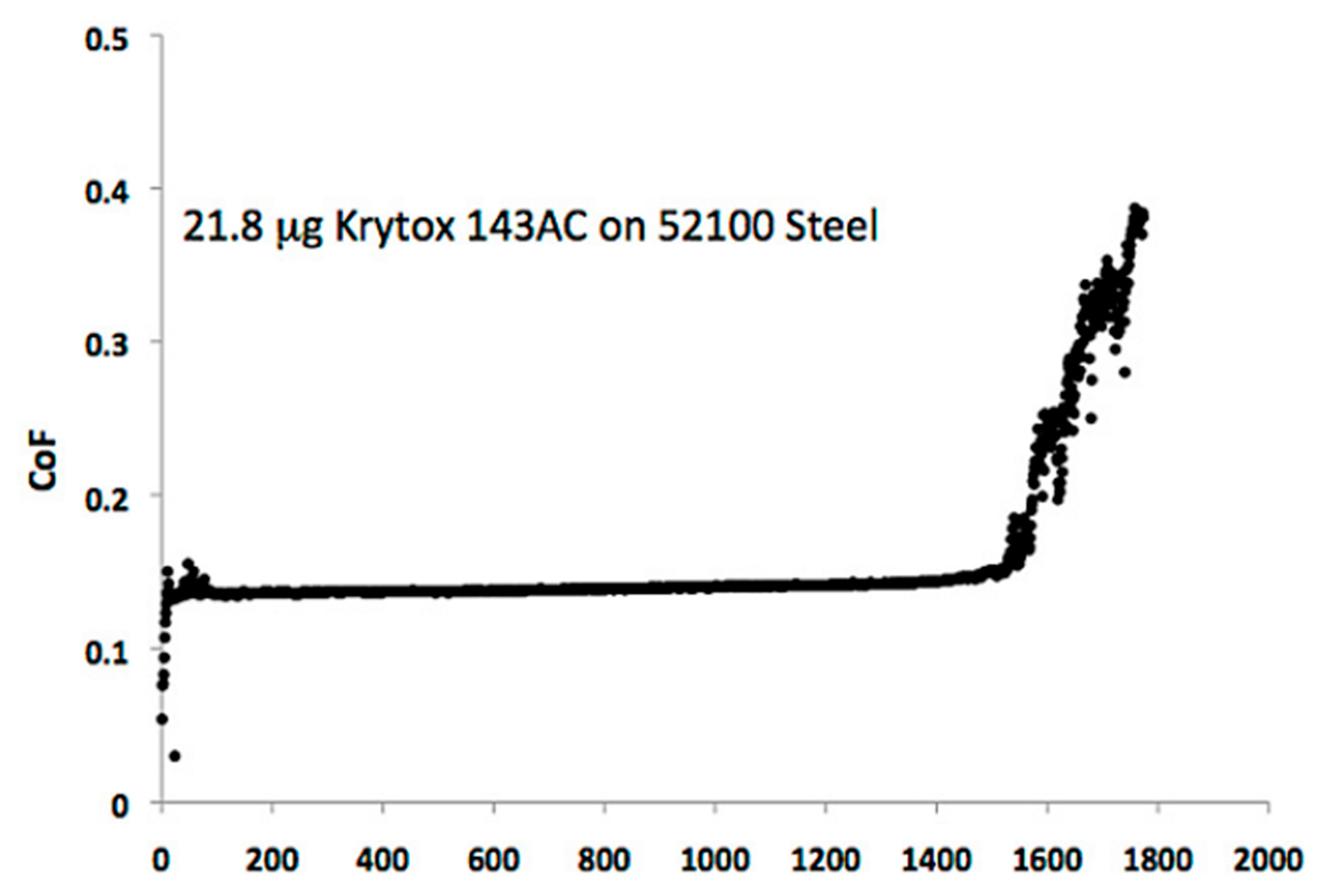
Torque is the most direct measurement of bearing health [28]. CERES torque trending behavior with time/cycles has 4 phases [29]. The first phase is a run-in period. The second phase is a long period of stable torque followed by a third phase of gradual increases in torque. The final phase is a sudden catastrophic rise (Figure 3). The run-in period is where the lubricant is distributed. The rise in the last phase is often termed exponential or runaway [30]. Oscillatory gimbal motion on CERES can give rise to undesired friction and torque losses [31].
Debris mounds can form and accumulate at the end of each stroke (Bazinet, 2004). The result is an increase in torque, labeled a torque bump. The change in the appearance of torque bumps are the earliest observable indicator of lubricant breakdown [12,31]. Lubricant breakdown is a precursor to gimbal failure. Torque bumps are difficult to quantify. They most prominently occur at the reversal of the given gimbal scanning directions. This occurs at a gimbal velocity of 0.
Two methods are used herein for examining and interpreting the CERES torque behavior [32]. These methods are consistent with those used in the earlier CERES gimbal ground test. These are the running torque and the torque bump. The former uses data from the constant velocity portions of the scan. These are determined by the difference (clockwise v counterclockwise) between the average highest and the average lowest torque value. The resulting value is then divided by two. The second is determined by the difference between the relative largest positive and largest negative readings (peaks). This occurs during the scan velocity reversals. This also occurs for the onset of dwells in the elevation scans [7]. It was experimentally observed that torque bumps are more sensitive to parametric change than running torque.
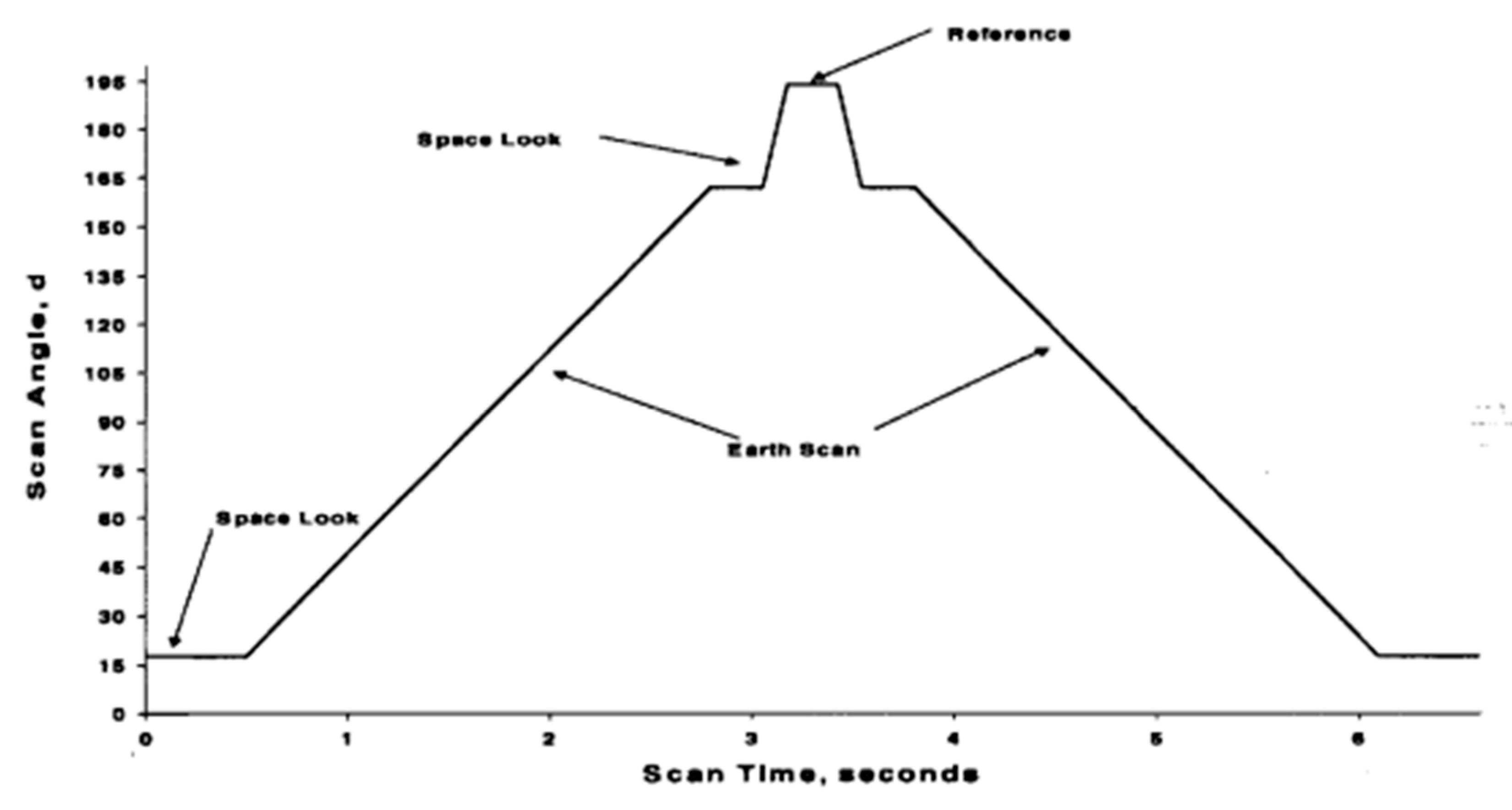
Both methods lend themselves to the available CERES position error data. These data are for both the azimuth and elevation gimbals. The normal elevation scan has four dwells in a single scan. A dwell occurs when a gimbal is at a certain position for a finite time (Figure 4). A single scan is 6.6 s. Local minimum and maximums occur at the start and end of a dwell. These occur at a change from or to constant velocity. These elevation position error data behave more like torque bumps than running torque. The errors at these 8 locations have been trended. This was done for all elevation gimbals. Approximate values for a typical normal elevation scan are shown in Table 2 below.
The flight goal for the azimuth gimbal running torque was to remain less than or equal to 58 in-oz (0.410 N-m). The flight goal for the elevation gimbal running torque was to remain less than or equal to 11 in-oz (0.078 N-m). These goals are also termed the worst cases or design limits. These goals were calculated for the lowest operating temperature. The bearing torque should be highest at the lowest operating temperature. There are no flight goals for torque bump.
In addition to directly observing torque, mean position error is an indicator of gimbal health. These are the CERES starting data. In CERES, this mean error tracks linearly with torque. The multiplier is the steady-state gain. This gain encompasses the torques and frictional effects mentioned above. In CERES, the significant mean running losses are friction, viscous drag, and cogging.
The steady-state torque (N-m), written in terms of the error count, is given by the equation below [33]:
where:
- = Digital to Analog scale factor; V/count
- = controller forward gain; V/V
- = driver current closed loop gain; amp/V
- = motor torque constant; in-oz/amp
- = steady-state gain; in-oz/count
The steady-state gain (Kss) for CERES elevation gimbals is 0.0367. The steady-state gain (Kss) for CERES azimuth gimbals is 0.085.
3. Results
3.1. Lubricant Loss
A simple calculation of evaporative lubricant loss has been applied. This is the modified Langmuir equation. The above calculations (see Section 2) used the present Terra flight time of 20 years. The starting masses of lubrication on the two Terra elevation cavities (flex cable side and motor side) are estimated as 369 mg and 407 mg, respectively. Minimal changes resulted from different vapor pressures. Increasing the fluid vapor pressure from 1.2701 × 10⁻¹⁰ (torr) (1.69 × 10⁻⁸ Pa) to 2.47 × 10⁻¹⁰ (torr) (3.29 × 10⁻⁸ Pa) increased the elevation mass loss rate to 1.04 × 10⁻¹² g/s. The starting mass of the lubrication in the azimuth cavity is estimated as 6882 mg. The maximum azimuth mass loss rate was 6.14 × 10⁻¹² g/s.
Unpublished data indicate similar loss rates calculated with a Monte Carlo technique. The Monte Carlo technique is more computably intensive. A ground study on Pennzane evaporative loss indicated that the calculated mass loss is less than the observed mass loss. Given the azimuth and elevation labyrinth seal geometry, a correction factor of 100 is required [8]. This correction has been included in our calculations and is shown in Table 3. The worst case indicates that the elevation gimbal has lost 18% of the starting lubricant. Moreover, the worst case indicates that the azimuth gimbal has lost 6% of the starting lubricant. All models indicate that evaporative losses will not be a source of impending failure for both the azimuth and elevation gimbals. This affirms that the gimbal design and choice of lubricant results in minimal evaporative lubricant loss.
3.2. Torque
Three peaks and three valleys were extracted from each of the three elevation scans per diagnostic scan. One peak and one valley were extracted from one azimuth scan per diagnostic scan. All data points were collected at 10 microsecond intervals. This is the data collection rate. For a full diagnostic scan, there are 1981 elevation gimbal data sets and 6600 azimuth gimbal data sets.
Torque was calculated using the hysteresis behavior of the average elevation errors and average azimuth errors. The running torque was calculated from both the positive and negative constant velocity parts of this scan. The calculation incorporated 222 consecutive samples (1 elevation scan) each for the positive and negative average elevation errors. The calculation incorporated 2930 consecutive samples for part of the azimuth scan (from 92 to 268 degrees).
The constant velocity regions indicate little or no variation in torque between the scan edge and center. Here, the gimbal trace has a rectangular profile (Figure 5). This is indicative of good gimbal health. If the hysteresis plot is “U”-shaped [34] or, conversely, barrel-shaped [35], degradation may be present.
There were 3 normal elevation scans per diagnostic scan. These scans are termed crosstracks. The running torque was independently calculated and plotted for azimuth gimbal and elevation gimbal. Prior to launch, a CERES model underwent testing. This was an accelerated ground-based test. Only the elevation gimbal was studied. The gimbal friction (torque) was between 8.5 and 9 in-oz (0.060 to 0.063 N-m) [7].
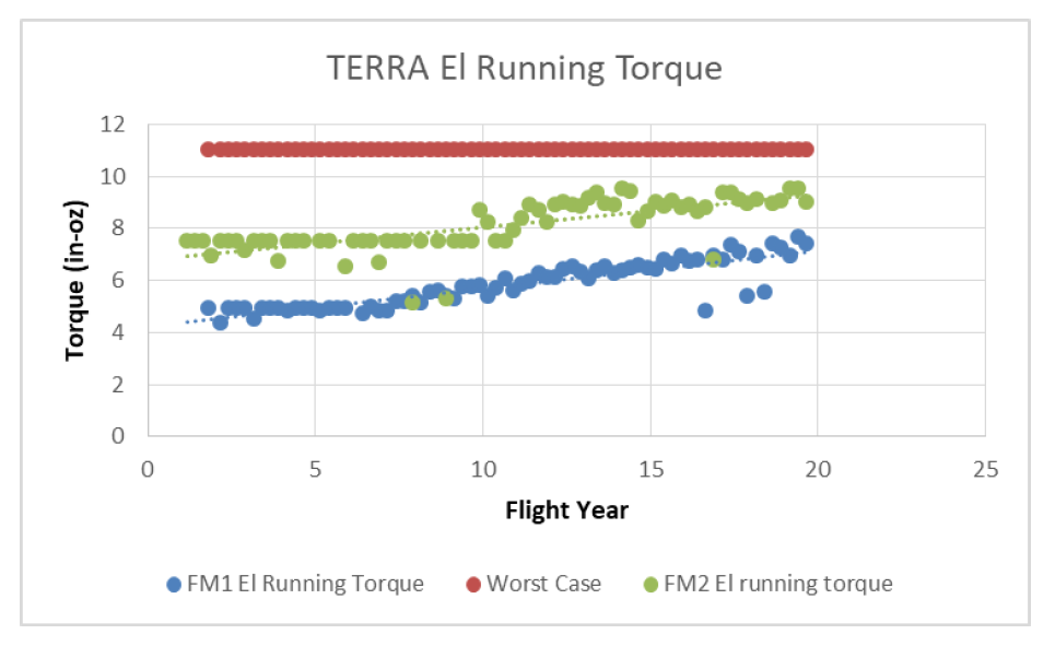
The elevation gimbal plots show the running torque trending data (Figure 6). There is a gradual rise in torque with time. These data sets correspond to the bearing lifetime phase 3. The phase 3 sections of the elevation running torque remain well below the 11 in-oz (0.078 N-m) worst case. The transition to phase 3 began after 10 flight years for FM2 and after 8 flight years for FM1. This is potentially the onset of degradation. The phase 3 running torque data were linearly fit with the flight year. Extrapolation indicates that the torque values will not reach the worst-case value before 40 flight years.
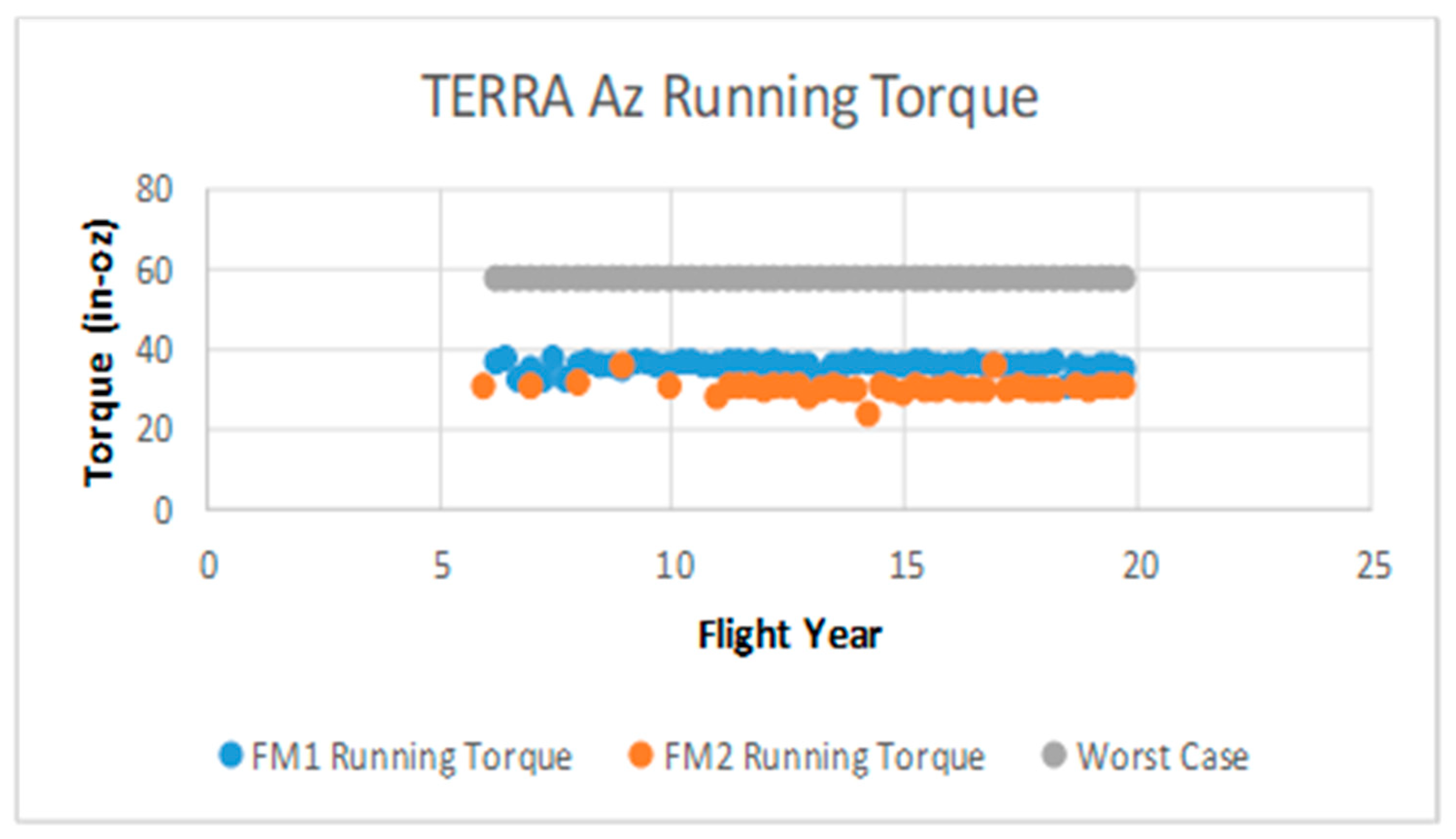
The azimuth gimbal plots show the running torque trending data (Figure 7). The azimuth gimbal running torque trending remains well below the 58 in-oz (0.410 N-m) worst case. The plot shows a long period of continuous stable torque. These data sets correspond to the bearing lifetime of phase 2. Contrasting the running torque with flight time, the azimuth gimbal is in a more stable state than the elevation gimbal. One factor is the cumulative operating cycles. The operating cycles of the azimuth gimbal are an order of magnitude less than the operating cycles of the elevation gimbal.
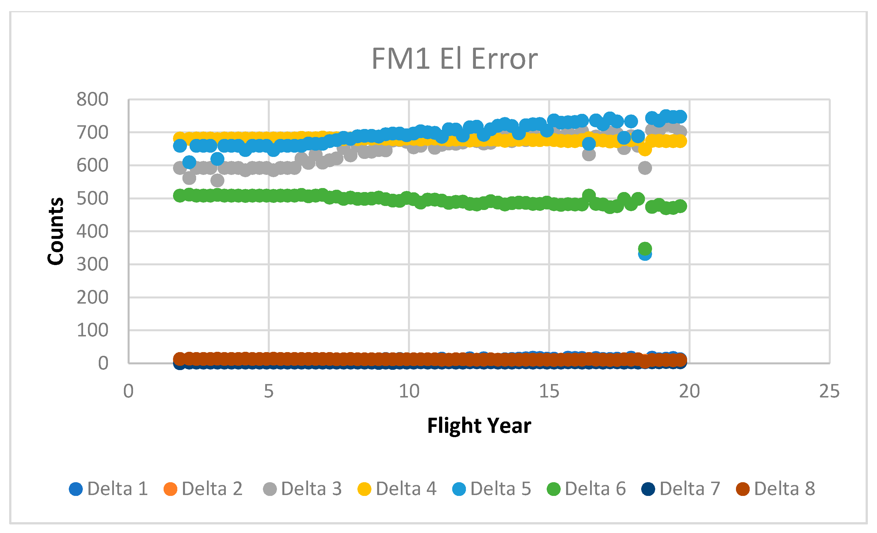
The torque bump was also plotted. This is for both azimuth gimbals and elevation gimbals. To enhance accurate trending, the relative torque bumps on the elevation gimbal were considered. These transitions and positions are listed in the above Table 3. The relative peak magnitudes show consistent increases in torque with the increase in angular rate. This is expected behavior. The magnitudes of Deltas 3-6 are higher than Delta 1,2 and 7,8.
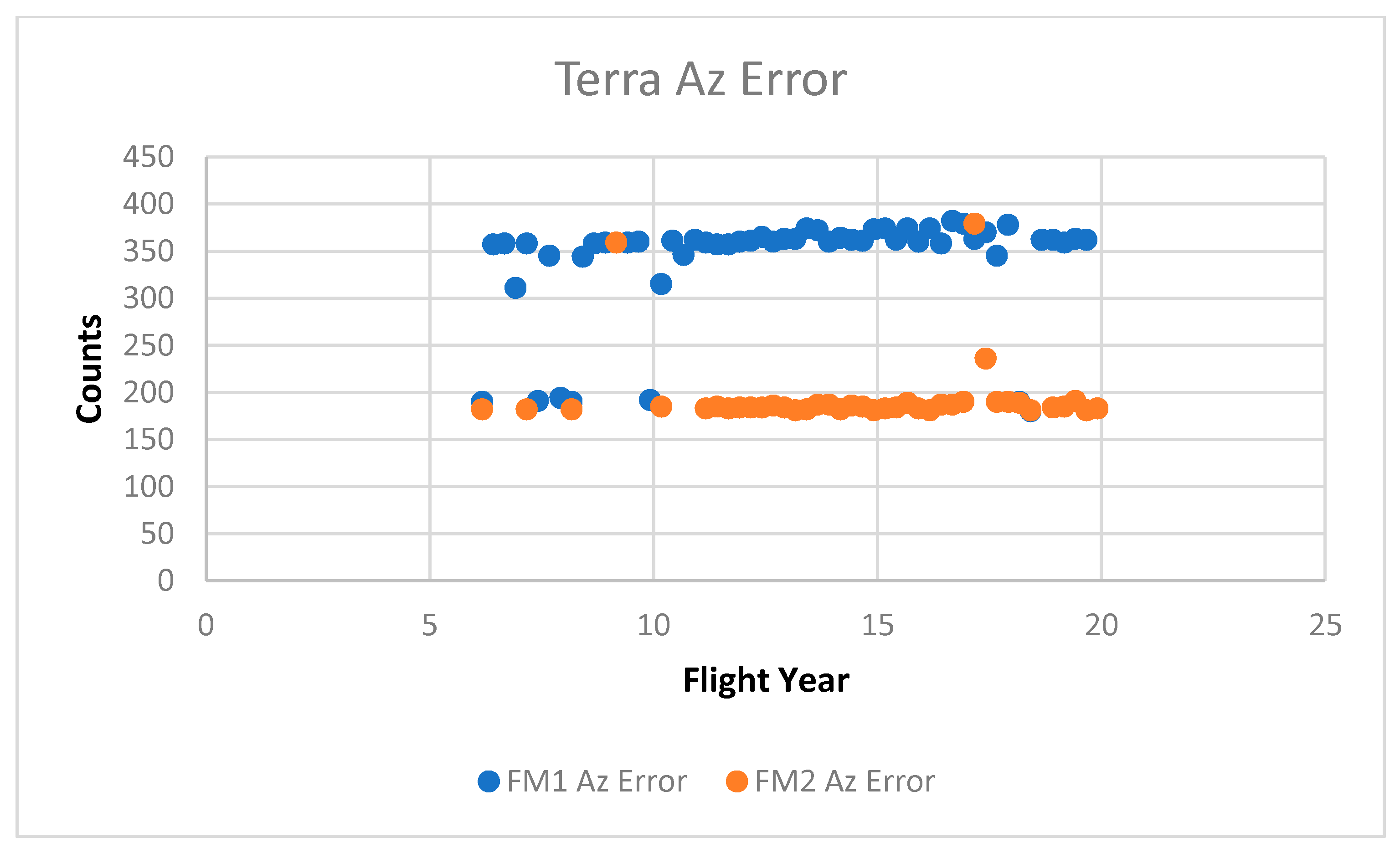
Plotting the relative peaks to valleys for the elevation gimbal position error per scan shows a consistent linear increase with flight years (Figure 8 and Figure 9). Plotting the maximum peak to valley for the azimuth gimbal position error per scan shows a consistent linear increase with flight years (Figure 10). The asymmetric shape (magnitude) observed at the torque trace endpoints is not unexpected. [36].
4. Discussion and Conclusions
This investigation focused on quantitatively describing the present health and expected life of the CERES gimbals on the Terra satellite. This was accomplished by trending friction torque and calculating evaporative lubricant loss.
CERES was well conceived to provide flight position error data by telemetry, allowing for the assessment of bearing lubrication lifetime trending and of gimbal degradation. Flight position error data have been continuously collected quarterly over the life of the instrument.
Bearings were formed from AISI 440C steel. Bearing assemblies are lubricated with Pennzane 2000 and additives. The evaporative lubricant loss rate was calculated using a modified Langmuir equation. This equation includes the beneficial effects of a labyrinth seal. Worst case losses on the elevation gimbals indicate that 18% of the starting lubricant has evaporated. Worst case losses on the azimuth gimbal indicate that 6% of the starting lubricant has evaporated. Lubrication loss should not be a factor in causing imminent damage to the elevation and azimuth gimbals.
Both azimuth and elevation gimbal position error were converted to running torque by simple scaling factors. There are many potential sources of parasitic torque. The scaling factors incorporate these sources. Bearing friction is the largest of the parasitic losses.
CERES torque trending behavior over time has four phases. The design limit for the elevation gimbals is 11 in-oz (0.078 N-m). Currently, the elevation gimbal is in phase 3. Phase 3 comprises a gradual rise in torque over time. Using a linear fit, the elevation gimbal torque will not reach the worst case for 40 flight years. This is indicative of good gimbal health.
The design limit for the azimuth gimbal is 58 in-oz (0.410 N-m). Currently, the azimuth gimbal is in phase 2. Phase 2 is a long period of stable torque with time. The azimuth running torque is well below the worst case. This is indicative of good gimbal heath. The azimuth gimbal is in a more stable state than the elevation gimbal. One factor is the cumulative operating cycles. The elevation gimbal operates nearly constantly and executes more cycles than the azimuth gimbal over time. The cumulative number of cycles on the elevation gimbal exceeds that on the azimuth gimbal by an order of magnitude.
Torque bump behavior was observed in the position error of both the azimuth and elevation gimbal scans. This occurred at times and positions of zero velocity, but did not increase in magnitude with flight time. While this transient response is sensitive to parametric change, it is difficult to quantify.
CERES elevation and azimuth gimbals have continually shown a nominal performance. They have been operating for over 20 flight years. They remain well within the subsystem design requirements. The design choices for the gimbals, bearings, and lubricant have resulted in a robust operation. The ultimate source of failure for the CERES gimbals will be lubricant loss from the contact areas. Wear and tribological damage are not primary sources of failure.
Funding
This research received no external funding.
Conflicts of Interest
The author declares no conflict of interest.
References
- Gardos, M.N. Labyrinth sealing of aerospace mechanisms. ASLE Trans. 1974, 17, 237–250. [Google Scholar] [CrossRef]
- Salmon, W.A.; Apt, C.M. A lubrication system for space vehicles. SAE Trans. 1964, 72, 79–86. [Google Scholar]
- Krishnan, S.; Lee, S.H.; Hsu, H.Y.; Konchady, G. Lubrication of attitude control systems. In Advances in Spacecraft Technologies; InTech: Rijeka, Croatia, 2011; pp. 75–98. [Google Scholar]
- Fusaro, R.L. Lubrication of Space Systems. Available online: https://ntrs.nasa.gov/archive/nasa/casi.ntrs.nasa.gov/19970003296.pdf (accessed on 26 November 2018).
- Loewenthal, S.; Jones, W.; Grout, J.; Predmore, R.; Thorn, R. Instrument Bearing Life with Non-CFC Cleaners. Available online: https://ntrs.nasa.gov/archive/nasa/casi.ntrs.nasa.gov/20010071561.pdf (accessed on 16 January 2015).
- Sathyan, K.; Hsu, H.Y.; Lee, S.H.; Gopinath, K. Long-term lubrication of momentum wheels used in spacecrafts—An overview. Tribol. Int. 2010, 43, 259–267. [Google Scholar] [CrossRef]
- Brown, P.L.; Miller, J.B.; Jones, W.R., Jr.; Rasmussen, K.; Wheeler, D.R.; Rana, M.; Peri, F. The Clouds and the Earth’s Radiant Energy System Elevation Bearing Assembly Life Test. Available online: https://ntrs.nasa.gov/archive/nasa/casi.ntrs.nasa.gov/19990053852.pdf (accessed on 27 November 2018).
- Anderson, M.J.; Freeman, S.; Roberts, E.W. Evaporative losses of vacuum-compatible oils through labyrinth seals. In Proceedings of the 10th European Space Mechanisms and Tribology Symposium, San Sebastian, Spain, 24–26 September 2003. [Google Scholar]
- Jones, W.R., Jr.; Poslowski, A.K.; Shogrin, B.A.; Herrera-Fierro, P.; Jansen, M.J. Evaluation of several space lubricants using a vacuum four-ball tribometer. Tribol. Trans. 1999, 42, 317–323. [Google Scholar] [CrossRef] [Green Version]
- Loewenthal, S.; Jones, W.; Predmore, R. Life of Pennzane and 815Z-Lubricated Instrument Bearings Cleaned with Non-CFC Solvents. Available online: https://ntrs.nasa.gov/archive/nasa/casi.ntrs.nasa.gov/19990095611.pdf (accessed on 8 October 2014).
- Jansen, M.J.; Jones, W.R., Jr.; Predmore, R.E.; Loewenthal, S.L. Relative Lifetimes of Several Space Liquid Lubricants Using a Vacuum Spiral Orbit Tribometer (SOT). Available online: https://ntrs.nasa.gov/archive/nasa/casi.ntrs.nasa.gov/20010069634.pdf (accessed on 11 April 2019).
- Bazinet, D.G.; Espinosa, M.A.; Loewenthal, S.H.; Gschwender, L.; Jones, W.R., Jr.; Predmore, R.E. Life of scanner bearings with four space liquid lubricants. J. Synth. Lubr. 2006, 23, 81–90. [Google Scholar] [CrossRef]
- Buttery, M. An Evaluation of Liquid, Solid, and Grease Lubricants for Space Mechanisms Using a Spiral Orbit Tribometer. Available online: https://ntrs.nasa.gov/archive/nasa/casi.ntrs.nasa.gov/20100021923.pdf (accessed on 6 June 2018).
- Venier, C.; Casserly, E.W.; Jones, W.R., Jr.; Marchetti, M.; Jansen, M.J.; Predmore, R.E. Tribological Properties of a Pennzane (Registered Trademark)-Based Liquid Lubricant (Disubstituted Alkylated Cyclopentane) for Low Temperature Space Applications. Available online: https://ntrs.nasa.gov/archive/nasa/casi.ntrs.nasa.gov/20020050211.pdf (accessed on 16 September 2015).
- Peterangelo, S.C.; Gschwender, L.; Snyder, C.E., Jr.; Jones, W.R., Jr.; Nguyen, Q.; Jansen, M.J. Improved additives for multiply alkylated cyclopentane-based lubricants. J. Synth. Lubr. 2008, 25, 31–41. [Google Scholar] [CrossRef]
- Hilton, M.R.; Fleischauer, P.D. Lubricants for High-Vacuum Applications; The Aerospace Corporation: El Segundo, CA, USA, 1993. [Google Scholar]
- Aerospace Products: Oils. Available online: https://www.nyelubricants.com/stuff/contentmgr/files/0/8b17e8eb040695b7b90019c9cc9c65f5/en/aerospace_matrix_oil__brochure.pdf (accessed on 1 February 2020).
- Morales, W.; Street, K.W., Jr.; Koch, V.R.; Richard, R.M. Evaluation of vapor pressure and ultra-high vacuum tribological properties of ionic liquids (2) mixtures and additives. In Proceedings of the STLE/ASME International Tribology Conference, Miami, FL, USA, 20–22 October 2008. [Google Scholar]
- Carre, D.J.; Bertrand, P.A. Modeling and measurement of aryl phosphate ester vapor pressures at 50C. Tribol. Trans. 1999, 42, 777–782. [Google Scholar] [CrossRef]
- Carre, D.J.; Bertrand, P.A. A model to calculate evaporative oil loss in spacecraft mechanisms. Tribol. Trans. 1999, 42, 282–288. [Google Scholar] [CrossRef]
- Roberts, E.W. Space tribology: Its role in spacecraft mechanisms. J. Phys. Appl. Phys. 2012, 45, 503001. [Google Scholar] [CrossRef]
- Scialdone, J.J.; Miller, M.K.; Montoya, A.F. Methods of Measuring Vapor Pressures of Lubricants with Their Additives Using TGA and/or Microbalances. Available online: https://ntrs.nasa.gov/archive/nasa/casi.ntrs.nasa.gov/19960022382.pdf (accessed on 1 February 2020).
- Nguyen, Q.N.; Jones, W.R., Jr. Volatility and wear characteristics of a variety of liquid lubricants for space applications. Tribol. Trans. 2001, 44, 671–677. [Google Scholar] [CrossRef]
- Dushman, S. Scientific Foundations of Vacuum Technique; JW Wiley & Sons: New York, NY, USA, 1962. [Google Scholar]
- Bialke, B. Space-flight experience and life test performance of a synthetic hydrocarbon lubricant. In Proceedings of the 6th European Space Mechanisms and Tribology Symposium, Zurich, Switzerland, 4–6 October 1995. [Google Scholar]
- Prat, P.; Vergne, P.; Sicre, J. New results in high pressure and low temperature rheology of liquid lubricants for space applications. J. Tribol. 1994, 116, 629–634. [Google Scholar] [CrossRef]
- Palladino, M.; Murer, J.; Didierjean, S.; Gaillard, L. Life prediction of fluid lubricated space bearings: A case study. In Proceedings of the 14th European Space Mechanisms and Tribology Symposium, Constance, Germany, 28–30 September 2011. [Google Scholar]
- Mobley, J.; Robertson, M.; Hodges, C. Extended life testing of duplex ball bearings. In Proceedings of the 43rd Aerospace Mechanisms Symposium, Santa Clara, CA, USA, 4–6 May 2016. [Google Scholar]
- Kalogeras, C.G.; Didziulis, S.V. Bearing Tests of Lubricant Additive Formulation and Pretreatment Processes; Aerospace Corporation: El Segundo, CA, USA, 1995. [Google Scholar]
- Fleischauer, P. Performance of fluid and solid lubricants in spacecraft applications. J. Synth. Lubr. 1995, 12, 1–12. [Google Scholar] [CrossRef]
- Loewenthal, S.H. Two gimbal bearing case studies: Some lessons learned. In Proceedings of the 22nd Aerospace Mechanisms Symposium, Hampton, VA, USA, 4–6 May 1988. [Google Scholar]
- Bauer, R.; Fleischauer, P.D. Torque Characteristics of Solid Lubricated Precision Bearings during Oscillatory Motion; The Aerospace Corporation: El Segundo, CA, USA, 1994. [Google Scholar]
- Miller, J.; Langley Research Center, Hampton, VA, USA. Unpublished work. 2008.
- Todd, M.J. Investigation of Torque Anomaly in Oscillating PDM Bearings; ESA (ESTL) 49: Warrington, UK, 1981. [Google Scholar]
- Masuko, M.; Kishi, K.; Suzuki, A.; Obara, S. The lifetime of boundary lubrication performance of small-quantity applied liquid lubricants for space mechanisms evaluated with a vacuum reciprocating tribometer. Tribol. Trans. 2010, 53, 75–83. [Google Scholar] [CrossRef]
- Pellicciotti, J.; Loewenthal, S.; Jones, W.R., Jr.; Jumper, M. Hubble space telescope fine guidance sensor post-flight bearing inspection. In Proceedings of the 37th Aersospace Mecahnisms Symposium, Galveston, TX, USA, 19–21 May 2004. [Google Scholar]
Figure 1.
Elevation scanning assembly.

Figure 2.
Azimuth scanning assembly.

Figure 3.
Representative plot showing phases of torque behavior with time.

Figure 4.
Elevation gimbal scan profile.

Figure 5.
Elevation error counts vs. elevation angle for Flight Model 1 (FM1); constant velocity portions (CW/CCW).
Figure 5.
Elevation error counts vs. elevation angle for Flight Model 1 (FM1); constant velocity portions (CW/CCW).

Figure 6.
FM1 and FM2 elevation gimbal running torque; x-axis shows flight years.

Figure 7.
FM1 and Flight Model 2 (FM2) azimuth gimbal running torque; x-axis shows flight years.

Figure 8.
FM1 elevation error count difference; x-axis shows flight years.

Figure 9.
FM2 elevation error count difference; x-axis shows flight years.

Figure 10.
FM1 and FM2 azimuth error count difference; x-axis shows flight years.


Table 1.
CERES gimbal properties.
| Parameter | Elevation Gimbal | Azimuth Gimbal |
|---|---|---|
| Motion | oscillatory | oscillatory |
| Lubrication | MT7-5-4 | MT7-5-4 |
| Temperature | 0 °C to 30 °C (operating) | −10 °C to 30 °C (operating) |
| Scan period | 6.6 s | Variable |
| Degree range | 17.7°–194.0°–17.7°/scan (EOS) | 90°–270°–90° (typ.) |
| Bearing material | AISI-440-C steel | AISI-440-C steel |
| Bearing | Angular contact pair | Angular spaced pair |
| Number of balls | 34/17 | 62 |
| Ball diameter | 0.125 | 0.25 |
| Pre-load | 10–20 lbs. | 300-350 lbs. |
| Starting torque | 1.0/0.75 in.-oz. | 46 in.-oz. |
| Angular travel/cycle | 352° (typ.) | 360° (typ.) |
| Pressure (in orbit) | <1 × 10⁻⁶ torr | <1 × 10⁻⁶ torr |
Table 2.
Normal elevation scan command table.
| Time (s) | 0.5 | 2.79 | 3.05 | 3.17 | 3.42 | 3.54 | 3.8 | 6.09 |
|---|---|---|---|---|---|---|---|---|
| Event | Delta 1 | Delta 2 | Delta 3 | Delta 4 | Delta 5 | Delta 6 | Delta 7 | Delta 8 |
| Position (deg) | 17.8 | 162.3 | 162.3 | 194 | 194 | 162.3 | 162.3 | 17.8 |
| Direction | CW | CW | CCW | CCW | ||||
| Angular Rate (deg/s) | 0 | 63.1 | 0 | 249.7 | 0 | 249.7 | 63.1 | 0 |
Table 3.
Evaporative lubricant loss calculations.
| Lubricant Loss Model | Operating Time (Flight Year) | Vapor Pressure (Torr) | Temp, T (K) | Clausing Factor, F | Molecular Weight, M (g/mol) | Lube Loss Rate (g/s) | Mass Loss (mg) | Modified Mass Loss (mg) Anderson | Initial Lubricant Mass (mg) (Reservoir) |
|---|---|---|---|---|---|---|---|---|---|
| Modified Langmuir | |||||||||
| Elevation | 20 | 2.47 × 10⁻¹⁰ | 303 | 0.077 | 900 | 1.04 × 10⁻¹² | 0.657 | 65.7 | 367/409 |
| Elevation | 20 | 1.27 × 10⁻¹⁰ | 303 | 0.077 | 900 | 5.36 × 10⁻¹³ | 0.337 | 33.7 | 367/409j |
| Azimuth | 20 | 2.47 × 10⁻¹⁰ | 303 | 0.080 | 900 | 6.14 × 10⁻¹² | 3.87 | 387 | 6882 |
| Azimuth | 20 | 1.27 × 10⁻¹⁰ | 303 | 0.080 | 900 | 3.157 × 10⁻¹² | 1.99 | 199 | 6882 |
| Monte Carlo | |||||||||
| Elevation | 303 | 0.077 | 690 | 2.87 × 10⁻¹² | 225 | ||||
| Azimuth | 303 | 0.080 | 690 | 1.689 × 10⁻¹¹ | 6881 | ||||
© 2020 by the author. Licensee MDPI, Basel, Switzerland. This article is an open access article distributed under the terms and conditions of the Creative Commons Attribution (CC BY) license (http://creativecommons.org/licenses/by/4.0/).
Share and Cite
MDPI and ACS Style
Butler, J.C. CERES Gimbal Performance on Terra. Lubricants 2020, 8, 79. https://0-doi-org.brum.beds.ac.uk/10.3390/lubricants8080079
AMA Style
Butler JC. CERES Gimbal Performance on Terra. Lubricants. 2020; 8(8):79. https://0-doi-org.brum.beds.ac.uk/10.3390/lubricants8080079
Chicago/Turabian StyleButler, John C. 2020. "CERES Gimbal Performance on Terra" Lubricants 8, no. 8: 79. https://0-doi-org.brum.beds.ac.uk/10.3390/lubricants8080079
Note that from the first issue of 2016, this journal uses article numbers instead of page numbers. See further details here.