Roughness-Induced Adhesive Hysteresis in Self-Affine Fractal Surfaces


Department of Mechanics, Mathematics and Management, Polytechnic University of Bari, Via E. Orabona, 4, 70125 Bari, Italy
*
Author to whom correspondence should be addressed.
Lubricants 2021, 9(1), 7; https://0-doi-org.brum.beds.ac.uk/10.3390/lubricants9010007
Submission received: 1 December 2020
/
Revised: 30 December 2020
/
Accepted: 4 January 2021
/
Published: 7 January 2021
(This article belongs to the Special Issue Interfacial Dissipative Phenomena in Tribomechanical Systems)
Abstract
:It is known that in the presence of surface roughness, adhesion can lead to distinct paths of loading and unloading for the area–load and penetration–load relationships, thus causing hysteretic loss. Here, we investigate the effects that the surface roughness parameters have on such adhesive hysteresis loss. We focus on the frictionless normal contact between soft elastic bodies and, for this reason, we model adhesion according to Johnson, Kendall, and Roberts (JKR) theory. Hysteretic energy loss is found to increase linearly with the true area of contact, while the detachment force is negligibly influenced by the maximum applied load reached at the end of the loading phase. Moreover, for the micrometric roughness amplitude considered in the present work, adhesion hysteresis is found to be affected by the shorter wavelengths of roughness. Specifically, hysteresis losses decrease with increasing fractal dimension and cut-off frequency of the roughness spectrum. However, we stress that a different behavior could occur in other ranges of roughness amplitude.
1. Introduction
The hysteretic dissipation is given by the difference between the work needed to bring two bodies into contact and that required to detach them. Its origin may be related to various phenomena occurring at the contact interface. The main causes of hysteresis are viscoelasticity [1,2], plasticity [3], adhesive elastic instabilities at jump-in and jump-out of contact [4], and surface roughness [5]. In particular, all natural and artificial surfaces are rough at some scale. Therefore, hysteretic losses may affect several technological applications. For example, biomedical devices [6] and structural adhesives [7] must safely adhere to surfaces during their application, but they should be easy to remove for reuse. Moreover, a recent challenge in soft robotics is to create climbing robots with reversible adhesion skills [8].
In contact experiments on soft matter, velocity-dependent dissipations are usually measured during detachment as a consequence of bulk viscoelasticity [9]. In a recent work [5], Dalvi et al. carried out loading–unloading contact experiments between smooth silicone hemispheres and rough nanodiamond substrates. Their experiments were performed at very low velocities (60 nm/s) both for the approach and detachment. Such choice allows the avoidance of velocity-dependent dissipations. However, great adhesion hysteresis was still observed due to the roughness-induced increase in the true contact area. This effect is expected to occur in compliant materials with small root mean square (rms) roughness amplitude ( 1 nm) [1], when they are bring in complete contact. Moving from the assumption of full-contact conditions, Dalvi et al. applied Persson and Tosatti (PT) adhesion theory [10] for predicting the magnitude of adhesion hysteresis. They found that the hysteretic dissipation increases almost linearly with the true contact area A, and it is equal to the product between A and the intrinsic surface energy , which depends on the interfacial adhesive properties of contacting bodies.
In [11], it is experimentally shown that can both increase and decrease the effective adhesive surface energy with respect to the smooth case. Moreover, numerical simulations of continuum adhesive contacts [12] have shown that there is an optimal that leads to a maximization of the hysteretic loss and pull-off force. Such value of is found when the contact region turns from being simply connected to being multiply connected. Similarly, in [13] it is shown that the effective surface energy reaches a maximum for a certain that, for vanishing applied pressure, is quite close to the value above which the effective contact area A becomes smaller than the nominal one . Moreover, the enhancement in the adhesion for small is much larger for , where H is the Hurst exponent, as the roughness-induced increase in the surface area is smaller when .
For RMS roughness amplitudes of the order of few microns, the true area of contact is expected to be predominantly multiply connected. In such case, partial contact conditions occur and surface roughness leads to a reduction in the true area of contact. This in turn destroys adhesion. However, Kesari et al. [11] found that adhesion hysteresis can also be measured for relative large . Inspired by the experimental findings in [11], Deng and Kesari (DK) [14] developed an analytical model for estimating hysteresis losses in the adhesive elastic contacts under the assumption of large roughness. DK’s model captures the increase of adhesion hysteresis with the penetration, which is usually called depth-dependent hysteresis. Moreover, in this case, a linear increase of the hysteretic dissipation with the area of contact is observed.
Carbone et al. [15] developed a numerical code based on a Boundary Element Method (BEM) for predicting loading–unloading hysteresis loops in the adhesive elastic contact of fractal self-affine 1D rough profiles. Their simulations were conducted under partial contact conditions, with ranging from up to . Due to adhesion hysteresis, two distinct paths were obtained for loading and unloading curves of the area vs. load relation. In particular, they found two sources of energy dissipation, one occurring at small scales and the second one at large scales.
In [16,17], similar multiasperity models have been developed to estimate adhesion hysteresis. They moved from the pioneering Greenwood and Williamson (GW) model, in which roughness is described by a distribution of identical spherical asperities. Adhesion is then implemented according to the classical theory of Johnson, Kendall, and Roberts (JKR) [18]. In a loading–unloading cycle, each asperity exhibits a hysteretic dissipation, which is due to jump-in and jump-off contact instabilities. The total adhesion hysteresis is returned by the contribution of each asperity. However, such models are based on a simplistic description of the surface roughness and do not take into account the elastic coupling between contact regions.
In this work, we propose an investigation of the adhesive elastic contact of rough surfaces, described by self-affine fractal geometries, with an advanced multiasperity model taking into account lateral interactions of asperities according to the authors of [19,20] and adhesion according to JKR theory. Moreover, the model takes also account of the jump-in and jump-off contact instabilities occurring on each asperity.
2. Problem Statement
2.1. Adhesion Hysteresis of Smooth Elastic Spheres
JKR theory [18] is commonly used to predict adhesion of soft materials. In the case of spherical contact, the fundamental equations of JKR theory give the applied load and penetration as a function of the contact radius a
being R the radius of curvature, the composite elastic modulus of the contacting bodies and the interface adhesion energy.
Under controlled displacement conditions, JKR model predicts a jump into contact at . However, Wu [21], investigating the jump-in instability occurring in atomic force microscopy measurements, found that jump-in instability is reached at a critical gap . Such effect is due to van der Waals interactions acting between approaching bodies. Wu proposed an empirical formula for the jump-in distance (valid for ),
where is the so-called Tabor parameter [22] and is the range of attractive forces.
The above equation can be used to modify JKR theory to consider the jump-in critical distance (see in [23]).
Moreover, under displacement controlled conditions and during retraction, JKR theory predicts a jump-off instability at a critical penetration
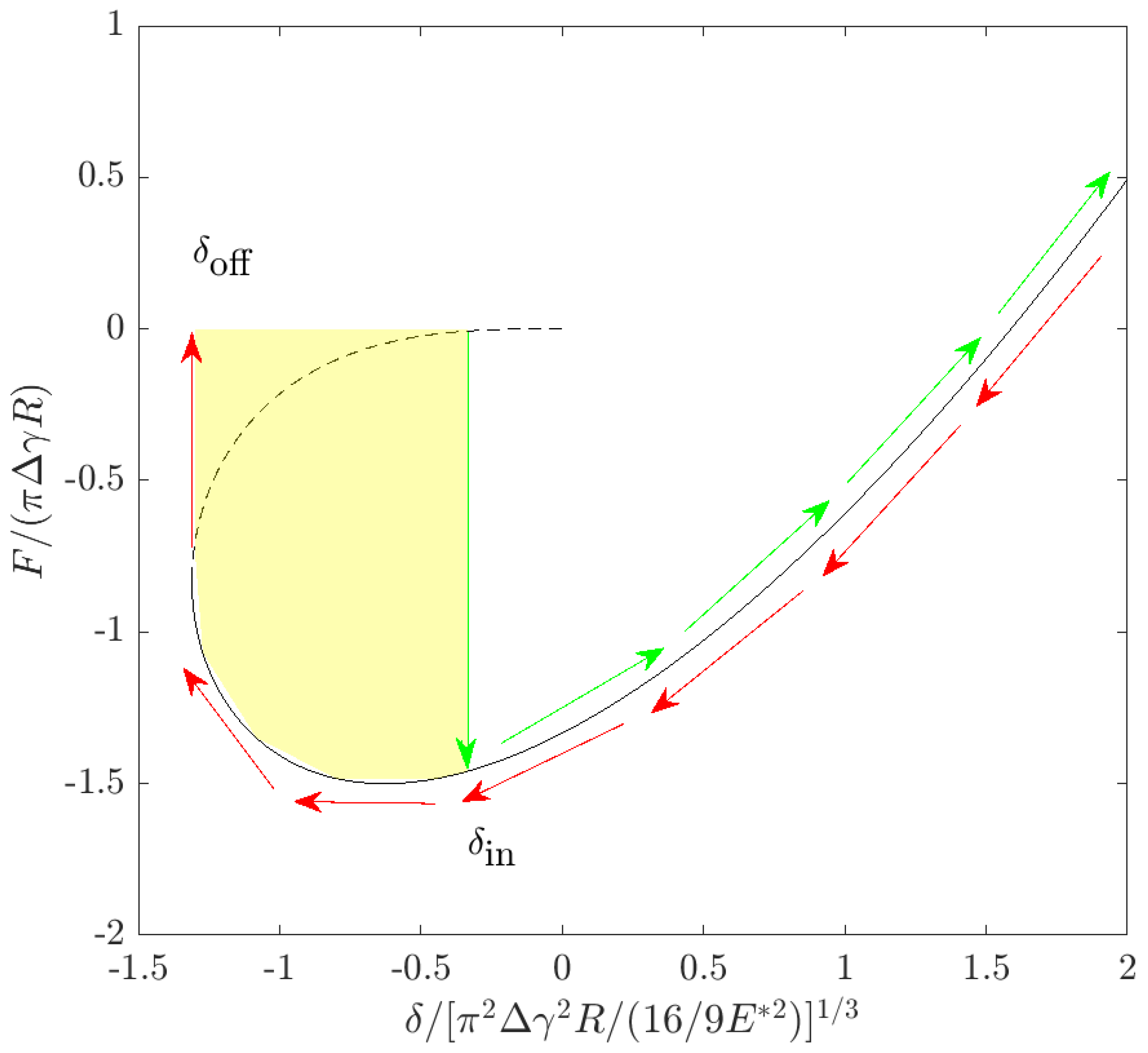
Figure 1 shows the loading-unloading cycle predicted by JKR theory. The yellow area represents the energy loss due to jumping instabilities. For smooth contact, the energy loss is independent on the maximum penetration (or, equivalently, applied force).
2.2. Adhesion Hysteresis of Rough Elastic Surfaces
In the case of rough surfaces, multiple unstable jumps occur at the location of each asperity in a loading–unloading cycle. To take account of this phenomenon, Equations (3) and (4) are implemented in a multiasperity model which in turn takes into account the elastic coupling due to asperities lateral interactions.
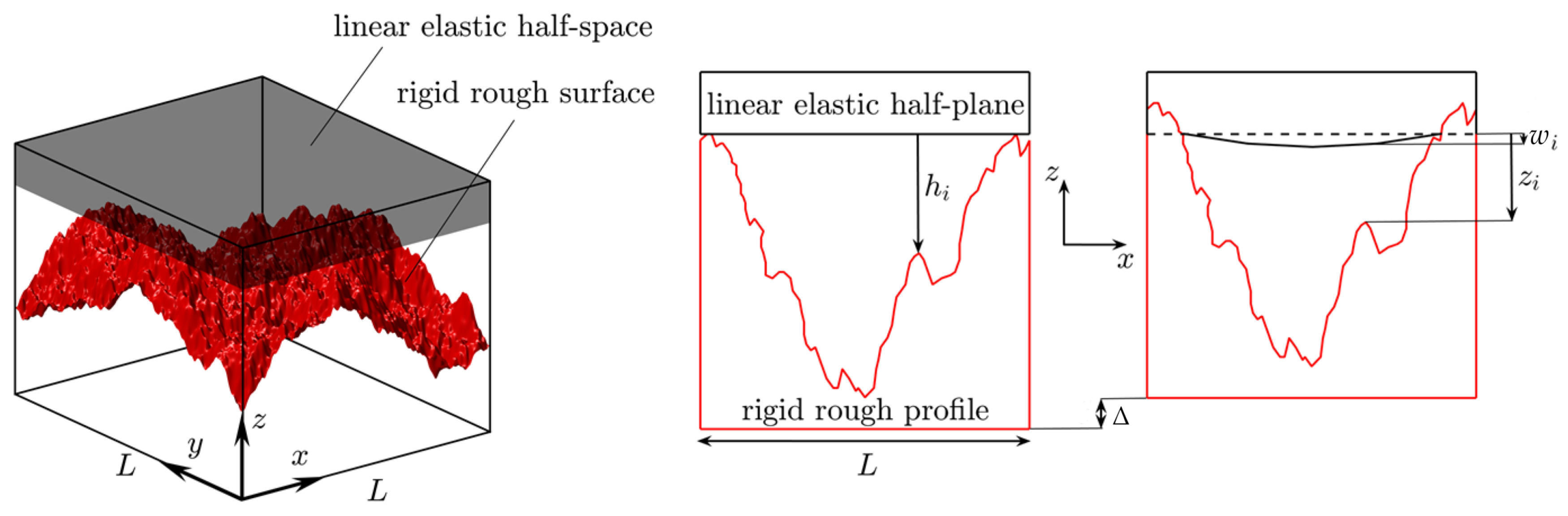
Let us consider a rigid rough surface approaching an elastic half-space (Figure 2). According to JKR formalism, the normal displacement of the elastic half-space at the location of the asperity i is
where is the displacement due to the elastic interaction between the asperities in contact and is given by [24]
where is the number of contact spots and is the distance between the asperities i and j.
When the rough surface approaches the half-space, a new contact is formed when the gap between an asperity and the half-space becomes smaller than , which is calculated for each asperity. A first estimate of the asperity contact radius is done by inverting the JKR relation (2). Then, after a further increment of the approach , being the height of the asperity i, the contact radius is increased by the quantity
which is obtained by differentiating Equation (2).
The total contact area and load are then obtained by summing up the contributions of all the asperities in contact. Moreover, as a self-balanced load distribution is considered, the interfacial mean separation is computed as , where and are the initial separation and the total approach, respectively.
3. Results
Computations have been performed on fractal self-affine isotropic surfaces. Roughness is described by its power spectral density (PSD), which has a power law relation with the magnitude of the wavevector . In this work, we consider fractal surfaces with PSD
and zero otherwise. We have denoted with and the short and long frequencies cut-off, respectively. The quantity L represents the lateral size of the domain (in this case ). Finally, H is the so-called Hurst exponent, which is related to the fractal dimension . Rough surfaces are numerically generated according to the spectral method proposed in [25,26].
In our calculations, we fixed mm and m. Furthermore, two sets of simulations have been performed. In the first one, we fixed and , with magnification 512. In the second one, we fixed and .
3.1. Adhesive Hysteresis and Pull-Off Force: Effect of Loading Parameters
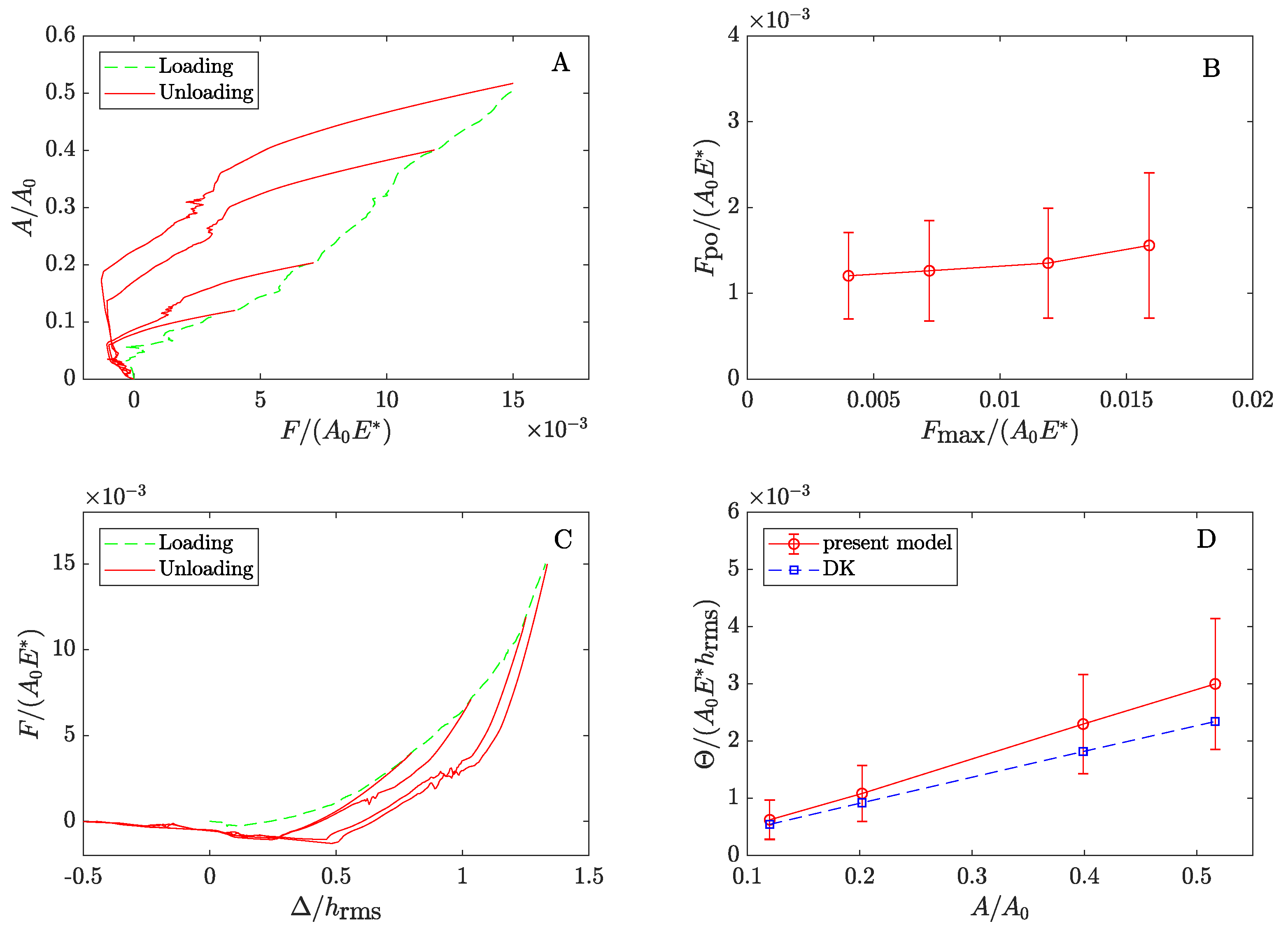
Figure 3A shows the normalized true contact area as a function of the dimensionless load . Calculations have been performed for , , and m. Moreover, the curves are obtained by averaging the results of six surface realizations. The material properties are MPa and J/m, which are typical values for very soft silicon elastomers. Unloading starts from different maximum applied loads .
For adhesiveless rough contacts, the area–load relation is known to be linear [27,28,29]. However, recent studies confirm that adhesion may lead to strong non-linearity of the curve [30,31,32]. In our calculations, this is especially true for the unloading path in agreement with numerical [15] and experimental [33] findings. The pull-off force is the maximum negative load reached during retraction. Near the pull-off point, unloading paths almost collapse on a single curve. As a result, the pull-off force is quite independent on the maximum true area of contact reached during the approach (Figure 3B). This is in agreement with experimental findings of Refs. [11,33].
In an approach–retraction cycle, the magnitude of hysteretic losses is equal to the area between the loading and unloading curves, where is the mean penetration of the rough surface in the half-space. Figure 3C shows the evolution of the dimensionless contact force with the normalized penetration . Recent experiments [5,11] suggest that, in presence of surface roughness, increases linearly with the penetration (or in a similar way with the true area of contact A). Such phenomenon is known in literature as depth-dependent hysteresis. Figure 3D shows the increase of the dimensionless energy loss with corresponding to the maximum applied loads. The model captures the linear relation between and and the analytical predictions given by DK’s model [14], as adapted to the present case (see Appendix A), are coherent with our numerical results.
3.2. Adhesive Hysteresis and Pull-Off Force: Effect of the Fractal Parameters
Surface roughness can be described by its statistical parameters, i.e., RMS roughness amplitude , RMS gradient , and RMS curvature . The first one is related to low frequencies of the PSD spectrum, while RMS slope and curvature mainly depends on the cut-off frequency and therefore on the magnification . Increasing , the PSD spectrum is enriched by smaller and smaller roughness wavelengths. An other important parameter is the Hurst exponent H. Low (high) values of H correspond to high (low) fractal dimension ().
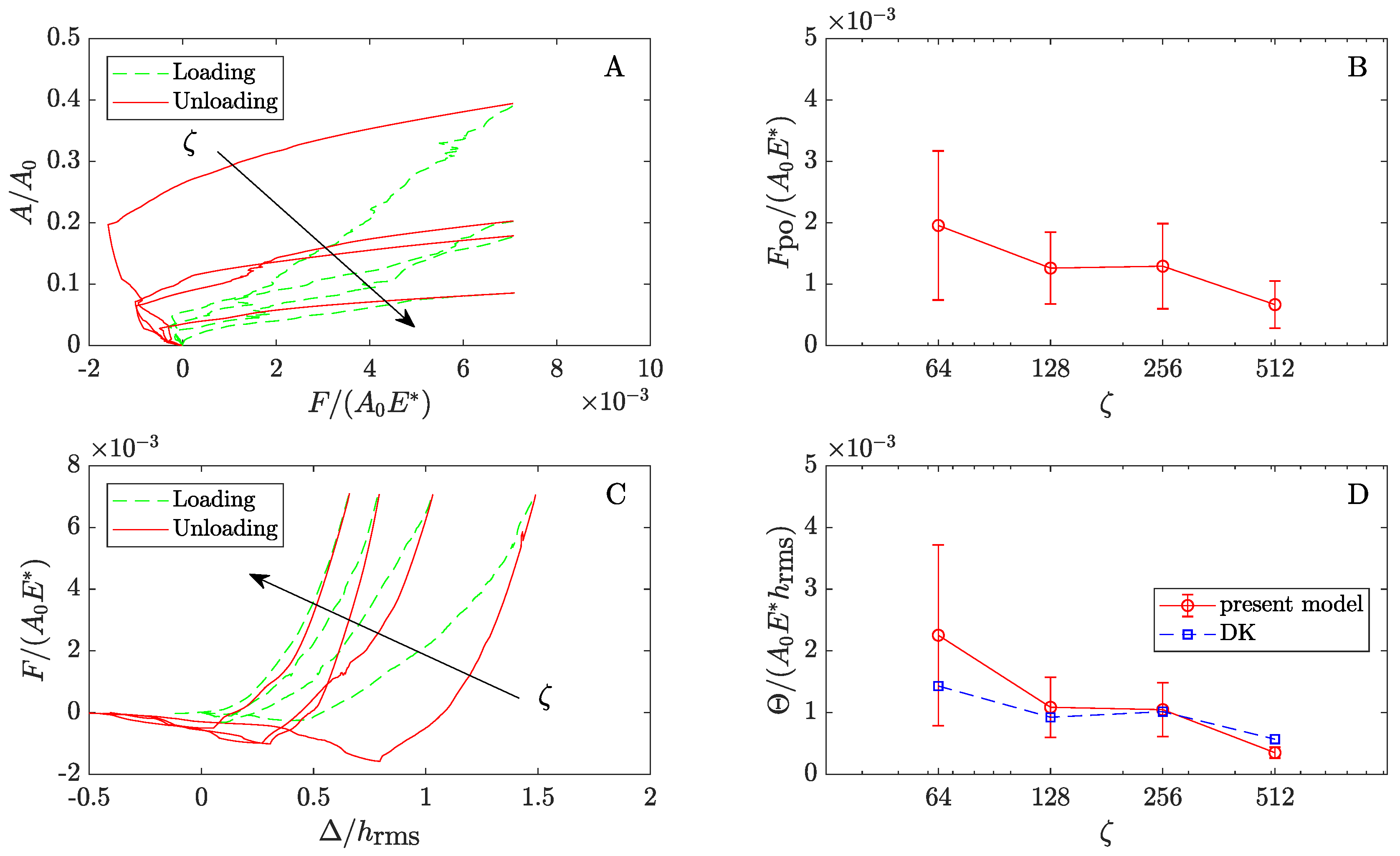
Figure 4A shows the relation at increasing values of the magnification ( 512) for m and . All curves are obtained for a same value of the applied load reached at the end of the approach, in similar way to the experiments performed in [5]. The true area of contact decreases with as an increase in corresponds to bigger rms gradient . In such case, surface roughness is described by several length-scales and a greater load is required to create new contact patches on smaller wavelengths. Specifically, as shown in [34], the dependence of the curves on (and thus on ) is exclusively due to the contribution of the repulsive interactions.
Figure 4B shows the dimensionless pull-off force as a function of the magnification. A general drop in the pull-off force is observed by increasing . This is in agreement with recent numerical findings in [35], where an in-house Boundary Element Method (BEM) has been developed for studying adhesive contact of rough surfaces, by including full Lennard–Jones potentials and surface integration at the asperity level. However, such results are due to the fact that we are considering surfaces with roughness amplitude of the order of microns. In fact, as found in [13], at sufficiently high values of the rms roughness amplitude (and more precisely of the product , being the roll-off frequency), for a decrease in magnification involves an increase in the effective surface energy at short length scale (large ). This effect results from the increase in the contact area as more a more short-wavelength roughness components are taken into account. However, we stress that such a result works as long as is high enough. Indeed, at lower , such effect is not observed and the adhesion seems to be governed only by the surface roughness amplitude [36].
In fact, for large and small , a model based on a JKR-type approach becomes questionable as the dimension of the contact spots decreases [37]. In such case, a DMT-type approach, based on the assumption of long-range adhesion interactions, could be more accurate in modeling the contact problem. In this regard, a DMT-type model is developed in [34] with the aim of investigating the adhesive contact of surfaces with of the order of 1 . It is found that is almost independent of , i.e., the adhesion force required for the detachment is magnification independent.This is confirmed in [38], where a stickiness criterion [38] is derived from Persson–Scaraggi DMT theory [37]. For typical values of the Hurst exponent (), the criterion suggests that adhesion is destroyed by the long wavelengths of roughness, while has negligible effects. Such result has been corroborated by very recent experimental [39] and analytical works [40,41], according to which the main parameter “killing” adhesion seems to be the roughness amplitude .
Figure 4C shows the load-penetration relationship for increasing magnification . The corresponding hysteretic losses are shown in Figure 4D. Our simulations suggest that the magnitude of energy loss follows the same trend of the pull-off force, i.e., it reduces with . Once again, DK’s predictions, as given by the proposed modified equation in appendix, are in agreement with our numerical calculations. The error bars in Figure 4B–D show the standard deviation on six surface realizations. The scatter is larger for surfaces with low magnification as a result of the smaller number of surface asperities. On the contrary, increasing , smaller and smaller asperities are added to the rough surface and their spatial distribution is expected to be more uniform in the nominal contact region. Moreover, as the linear size of the system is finite the PSD is not continuous and even assuming spectral components with random phases uniformly distributed in the range the surface will be not ergodic, and a single realization of the surface will be in general highly non-Gaussian, thus entailing finite-size effects related to the finite value of the asperities heights. It follows that for surfaces without a low-wavenumber roll-off (or cut-off) region, quantities which depend on the long wavelength roughness, such as the average interfacial separation (and hence the hysteresis dissipation) at low contact pressures, will vary strongly from one realization to another.
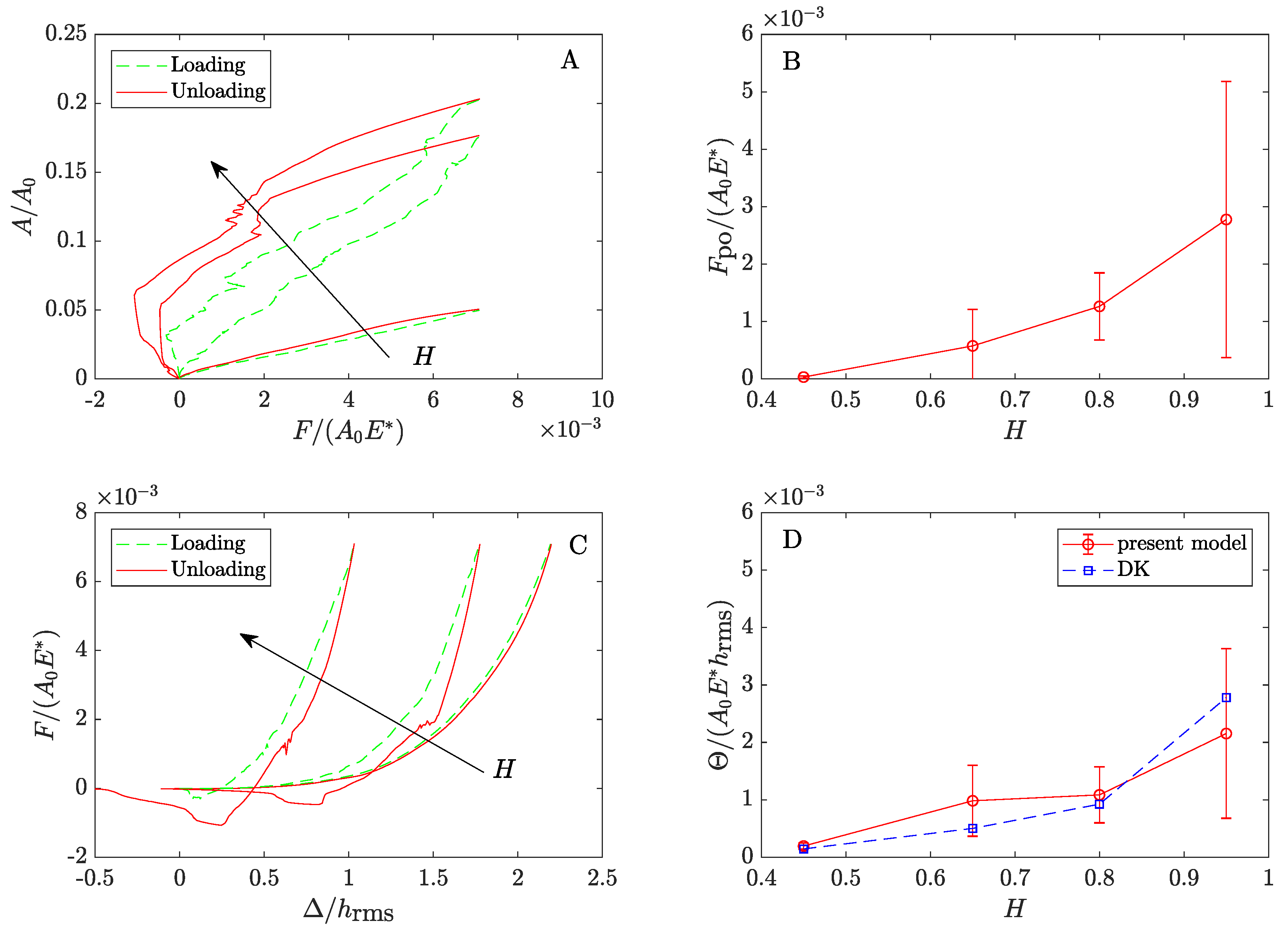
A second set of simulations has been performed on surfaces with fixed m, and different Hurst exponents . We have fixed again the maximum applied load . An increase in H leads to a decrease in RMS gradient, thus explaining why the area increases with H for a fixed load (Figure 5A). Figure 5B shows that the pull-off force is destroyed at low H; the same trend has been observed in [42], where the adhesive contact between a parabolic indenter with superimposed roughness and an elastic half space has been studied in the JKR-limit. Figure 5C shows how the relation modifies with H. In particular, at loading and unloading paths overlaps thus showing vanishing adhesive hysteretic loss , which is strongly affected by the Hurst exponent as shown in Figure 5D. Notice results are more scattered for surfaces with lower fractal dimension as finite-size effects related to the absence of a low-wavenumber roll-off (or cut-off) region are exaggerated at higher values of H.
4. Discussion and Conclusions
In the adhesive contact between an elastic half-space and a rigid randomly rough surface, loading-unloading loops can be observed as a result of adhesion hysteresis induced by roughness. Hysteretic losses are found to be linearly increasing with the true area of contact reached at the end of the loading path. On the contrary, the pull-off force is negligibly influenced by the maximum contact area (and thus maximum applied load).
Pull-off force and hysteretic losses are strongly affected by roughness parameters. Specifically, here we have investigated the effects of the Hurst exponent H and magnification .
Detachment force and hysteretic losses are observed to reduce by decreasing H and increasing . Such results are related to the increase in the RMS gradient occurring when H is reduced or is increased. Our outcomes are in agreement with the trends shown by very recent numerical, experimental and analytical findings.
However, we stress that our results are obtained on surfaces with RMS roughness amplitude of the order of few micrometers where we can reasonably expect partial contact conditions occur in a wide range of applied loads. In fact, multiasperity models become progressively less accurate moving towards full contact conditions. Moreover, numerical models allow to consider a limited range of magnifications, while real surfaces are characterized by roughness on several length scales (with the modern technologies we can measure , ranging from centimeter to nanometer scales). Despite such limitations, the present findings help to clarify some aspects of the hysteretic phenomenon occurring in the adhesive contact of rough soft matter.
Author Contributions
G.V. and L.A. contributed equally to this work. All authors have read and agreed to the published version of the manuscript.
Funding
This work was supported by the project “FASTire (Foam Airless Spoked Tire): Smart Airless Tyres for Extremely-Low Rolling Resistance and Superior Passengers Comfort” funded by the Italian MIUR Progetti di Ricerca di Rilevante Interesse Nazionale (PRIN) call 2017—grant n. 2017948FEN.
Informed Consent Statement
Informed consent was obtained from all subjects involved in the study.
Data Availability Statement
The data presented in this work are available on request from the corresponding author.
Acknowledgments
L.A. and G.V. acknowledge support from the Italian Ministry of Education, University and Research (MIUR) under the program “Departments of Excellence” (L.232/2016).
Conflicts of Interest
The authors declare no conflict of interest.
Appendix A. Deng and Kesari’s Model
Deng and Kesari’s model (DK) [14] is a combination of classical adhesive theories for smooth elastic spheres and Nayak’s theory of rough surfaces [43]. In their work, DK used both JKR [18] and Maugis–Dugdale [44] theories for estimating the energy loss in a loading–unloading cycle of a single spherical asperity. In the limit of high Tabor parameters (), the two theories predict the same behavior. For this reason, as our study is focused on very soft materials, for which high Tabor numbers are expected, here we discuss DK’s model in the framework of JKR theory.
DK gives an empirical estimate of the energy loss for a loading–unloading cycle of a single asperity of radius R; in the JKR limit the value of is
being .
For a rough surface the energy loss of each asperity depends on the value of its radius of curvature. Following the work in [43], the variation of curvature in the population of all asperities contained in any unit region is
where , being the surface’s mean curvature at the apex of an asperity, and the constants and are related to the Nayak parameter . The quantities , , and are the spectral moments of surface roughness PSD. In particular, they are related to the rms roughness amplitude , gradient and curvature by , , and .
Substituting (A2) in (A1) and integrating on the range of variation of t, the mean energy loss of contacting asperities can be written as
being .In DK’s model, is the radius of the spherical indenter that is in contact with a nominally flat surface. In our case, as contact occurs between nominally flat surfaces, .
Finally, the total energy loss can be computed as
where is the asperity density in a nominal contact region of unit area.
In the original DK’s model, the contact area A is computed applying JKR theory to the macroscopic spherical indenter of radius and neglecting roughness contribution. In particular, A is calculated as , where and are the values of the contact area at the maximum indentation and the macroscopic jump-in instability of the spherical tip, respectively.
In this work, as we are dealing with the contact between two nominally flat surfaces, is interpreted as the true contact area of the first few asperities jumping into contact, while is the true area of contact obtained at the end of the loading phase. Moreover, as in our calculations , we have assumed .
References
- Tiwari, A.; Dorogin, L.; Bennett, A.I.; Schulze, K.D.; Sawyer, W.G.; Tahir, M.; Heinrich, G.; Persson, B.N.J. The effect of surface roughness and viscoelasticity on rubber adhesion. Soft Matter 2017, 13, 3602–3621. [Google Scholar] [CrossRef]
- Violano, G.; Afferrante, L. Adhesion of compliant spheres: An experimental investigation. Procedia Struct. Integr. 2019, 24, 251–258. [Google Scholar] [CrossRef]
- Kim, J.Y.; Baltazar, A.; Rokhlin, S.I. Ultrasonic assessment of rough surface contact between solids from elastoplastic loading–unloading hysteresis cycle. J. Mech. Phys. Solids 2004, 52, 1911–1934. [Google Scholar] [CrossRef]
- Guduru, P.R.; Bull, C. Detachment of a rigid solid from an elastic wavy surface: Experiments. J. Mech. Phys. Solids 2007, 55, 473–488. [Google Scholar] [CrossRef]
- Dalvi, S.; Gujrati, A.; Khanal, S.R.; Pastewka, L.; Dhinojwala, A.; Jacobs, T.D. Linking energy loss in soft adhesion to surface roughness. Proc. Natl. Acad. Sci. USA 2019, 116, 25484–25490. [Google Scholar] [CrossRef] [Green Version]
- Pinnaratip, R.; Bhuiyan, M.S.A.; Meyers, K.; Rajachar, R.M.; Lee, B.P. Multifunctional biomedical adhesives. Adv. Healthc. Mater. 2019, 8, 1801568. [Google Scholar] [CrossRef] [PubMed]
- Kinloch, A.J. Adhesion and Adhesives: Science and Technology; Springer Science & Business Media: New York, NY, USA, 2012. [Google Scholar]
- Fiorello, I.; Tricinci, O.; Naselli, G.A.; Mondini, A.; Filippeschi, C.; Tramacere, F.; Mazzolai, B. Climbing Plant-Inspired Micropatterned Devices for Reversible Attachment. Adv. Funct. Mater. 2020, 30, 2003380. [Google Scholar] [CrossRef]
- Lorenz, B.; Krick, B.A.; Mulakaluri, N.; Smolyakova, M.; Dieluweit, S.; Sawyer, W.G.; Persson, B.N.J. Adhesion: Role of bulk viscoelasticity and surface roughness. J. Phys. Condens. Matter 2013, 25, 225004. [Google Scholar] [CrossRef] [PubMed]
- Persson, B.N.J.; Tosatti, E. The effect of surface roughness on the adhesion of elastic solids. J. Chem. Phys. 2001, 115, 5597–5610. [Google Scholar] [CrossRef] [Green Version]
- Kesari, H.; Doll, J.C.; Pruitt, B.L.; Cai, W.; Lew, A.J. Role of surface roughness in hysteresis during adhesive elastic contact. Philos. Mag. Philos. Mag. Lett. 2010, 90, 891–902. [Google Scholar] [CrossRef] [Green Version]
- Deng, W.; Kesari, H. Molecular statics study of depth-dependent hysteresis in nano-scale adhesive elastic contacts. Model. Simul. Mater. Sci. Eng. 2017, 25, 055002. [Google Scholar] [CrossRef]
- Persson, B.N.J. Adhesion between elastic bodies with randomly rough surfaces. Phys. Rev. Lett. 2002, 89, 245502. [Google Scholar] [CrossRef] [PubMed]
- Deng, W.; Kesari, H. Depth-dependent hysteresis in adhesive elastic contacts at large surface roughness. Sci. Rep. 2019, 9, 1–12. [Google Scholar] [CrossRef] [Green Version]
- Carbone, G.; Pierro, E.; Recchia, G. Loading-unloading hysteresis loop of randomly rough adhesive contacts. Phys. Rev. E 2015, 92, 062404. [Google Scholar] [CrossRef] [Green Version]
- Wei, Z.; He, M.F.; Zhao, Y.P. The effects of roughness on adhesion hysteresis. J. Adhes. Sci. Technol. 2010, 24, 1045–1054. [Google Scholar] [CrossRef] [Green Version]
- Greenwood, J.A. Reflections on and extensions of the Fuller and Tabor theory of rough surface adhesion. Tribol. Lett. 2017, 65, 159. [Google Scholar] [CrossRef] [Green Version]
- Johnson, K.L.; Kendall, K.; Roberts, A. Surface energy and the contact of elastic solids. Proc. R. Soc. Lond. A Math. Phys. Sci. 1971, 324, 301–313. [Google Scholar]
- Ciavarella, M.; Delfine, V.; Demelio, G. A “re-vitalized” Greenwood and Williamson model of elastic contact between fractal surfaces. J. Mech. Phys. Solids 2006, 54, 2569–2591. [Google Scholar] [CrossRef]
- Afferrante, L.; Carbone, G.; Demelio, G. Interacting and coalescing Hertzian asperities: A new multiasperity contact model. Wear 2012, 278, 28–33. [Google Scholar] [CrossRef]
- Wu, J.J. The jump-to-contact distance in atomic force microscopy measurement. J. Adhes. 2010, 86, 1071–1085. [Google Scholar] [CrossRef]
- Tabor, D. Surface Forces and Surface Interactions. In Plenary and Invited Lectures; Academic Press: Cambridge, MA, USA, 1977; pp. 3–14. [Google Scholar]
- Ciavarella, M.; Greenwood, J.A.; Barber, J.R. Effect of Tabor parameter on hysteresis losses during adhesive contact. J. Mech. Phys. Solids 2017, 98, 236–244. [Google Scholar] [CrossRef]
- Violano, G.; Afferrante, L. Modeling the adhesive contact of rough soft media with an advanced asperity model. Tribol. Lett. 2019, 67, 119. [Google Scholar] [CrossRef] [Green Version]
- Putignano, C.; Afferrante, L.; Carbone, G.; Demelio, G. A new efficient numerical method for contact mechanics of rough surfaces. Int. J. Solids Struct. 2012, 49, 338–343. [Google Scholar] [CrossRef] [Green Version]
- Putignano, C.; Menga, N.; Afferrante, L.; Carbone, G. Viscoelasticity induces anisotropy in contacts of rough solids. J. Mech. Phys. Solids 2019, 129, 147–159. [Google Scholar] [CrossRef]
- Afferrante, L.; Bottiglione, F.; Putignano, C.; Persson, B.N.J.; Carbone, G.J.T.L. Elastic contact mechanics of randomly rough surfaces: An assessment of advanced asperity models and Persson’s theory. Tribol. Lett. 2018, 66, 75. [Google Scholar] [CrossRef]
- Putignano, C.; Afferrante, L.; Carbone, G.; Demelio, G. The influence of the statistical properties of self-affine surfaces in elastic contacts: A numerical investigation. J. Mech. Phys. Solids 2012, 60, 973–982. [Google Scholar] [CrossRef]
- Muser, M.H.; Dapp, W.B.; Bugnicourt, R.; Sainsot, P.; Lesaffre, N.; Lubrecht, T.A.; Persson, B.N.J.; Harris, K.; Bennett, A.; Schulze, K.; et al. Greenwood Meeting the contact-mechanics challenge. Tribol. Lett. 2017, 65, 118. [Google Scholar] [CrossRef] [Green Version]
- Salehani, M.K.; van Dokkum, J.S.; Irani, N.; Nicola, L. On the load-area relation in rough adhesive contacts. Tribol. Int. 2020, 144, 106099. [Google Scholar] [CrossRef]
- Violano, G.; Afferrante, L. Contact of rough surfaces: Modeling adhesion in advanced multiasperity models. Proc. Inst. Mech. Eng. Part J. Eng. Tribol. 2019, 233, 1585–1593. [Google Scholar] [CrossRef]
- Violano, G.; Afferrante, L. On DMT methods to calculate adhesion in rough contacts. Tribol. Int. 2019, 130, 36–42. [Google Scholar] [CrossRef]
- Krick, B.A.; Vail, J.R.; Persson, B.N.; Sawyer, W.G. Optical in situ micro tribometer for analysis of real contact area for contact mechanics, adhesion, and sliding experiments. Tribol. Lett. 2012, 45, 185–194. [Google Scholar] [CrossRef]
- Violano, G.; Demelio, G.; Afferrante, L. A note on the effect of surface topography on adhesion of hard elastic rough bodies with low surface energy. J. Mech. Behav. Mater. 2019, 28, 8–12. [Google Scholar] [CrossRef]
- Ghanbarzadeh, A.; Faraji, M.; Neville, A. Deterministic normal contact of rough surfaces with adhesion using a surface integral method. Proc. R. Soc. A 2020, 476, 20200281. [Google Scholar] [CrossRef]
- Persson, B.N.J.; Sivebæk, I.M.; Samoilov, V.N.; Zhao, K.; Volokitin, A.I.; Zhang, Z. On the origin of Amonton’s friction law. J. Phys. Condens. Matter 2008, 20, 395006. [Google Scholar] [CrossRef]
- Persson, B.N.; Scaraggi, M. Theory of adhesion: Role of surface roughness. J. Chem. Phys. 2014, 141, 124701. [Google Scholar] [CrossRef] [PubMed] [Green Version]
- Violano, G.; Afferrante, L.; Papangelo, A.; Ciavarella, M. On stickiness of multiscale randomly rough surfaces. J. Adhes. 2019, 1–19. [Google Scholar] [CrossRef] [Green Version]
- Tiwari, A.; Wang, J.; Persson, B.N.J. Adhesion paradox: Why adhesion is usually not observed for macroscopic solids. Phys. Rev. E 2020, 102, 042803. [Google Scholar] [CrossRef] [PubMed]
- Joe, J.; Thouless, M.D.; Barber, J.R. Effect of roughness on the adhesive tractions between contacting bodies. J. Mech. Phys. Solids 2018, 118, 365–373. [Google Scholar] [CrossRef]
- Joe, J.; Scaraggi, M.; Barber, J.R. Effect of fine-scale roughness on the tractions between contacting bodies. Tribol. Int. 2017, 111, 52–56. [Google Scholar] [CrossRef]
- Li, Q.; Pohrt, R.; Popov, V.L. Adhesive Strength of Contacts of Rough Spheres. Front. Mech. Eng. 2019, 5, 7. [Google Scholar] [CrossRef] [Green Version]
- Nayak, P.R. Random Process Model of Rough Surfaces. J. Lubr. Tech. 1971, 93, 398–407. [Google Scholar] [CrossRef]
- Maugis, D. Adhesion of spheres: The JKR-DMT transition using a Dugdale model. J. Colloid Interface Sci. 1992, 150, 243–269. [Google Scholar] [CrossRef]
Figure 1.
The load–penetration curve predicted by Johnson, Kendall, and Roberts (JKR) theory. The loading (unloading) path is denoted by green (red) arrows. Positive penetration values correspond to indentation and compressive force. Jump into contact occurs at a penetration . The unloading path overlaps the loading one, but jump out of contact occurs at a critical penetration . The yellow area denotes the hysteretic energy loss.

Figure 2.
Elastic half-space in contact with a rigid rough surface.

Figure 3.
(A) The normalized area of contact as a function of the dimensionless load . Results are obtained on surfaces with m, and . Loading (green dashed line) and unloading (red solid line) curves are shown. Results are averaged on 6 surface realizations. (B) The dimensionless pull-off force as a function of the maximum applied load at the end of the loading phase. Error bars denote the standard deviation on 6 surface realizations. (C) The dimensionless mean penetration as a function of the applied load . (D) The dimensionless energy loss as a function of the normalized area of contact . Red solid and blue dashed lines refer to the present calculations and DK’s predictions, respectively. Error bars denote the standard deviation on 6 surface realizations.

Figure 4.
(A) The normalized area of contact as a function of the dimensionless load . Results are obtained on surfaces with m, , and . Loading (green dashed line) and unloading (red solid line) curves are shown. Results are averaged on 6 surface realizations. (B) The dimensionless pull-off force as a function of the magnification. Error bars denote the standard deviation on 6 surface realizations. (C) The dimensionless mean penetration as a function of applied load . (D) The dimensionless energy loss as a function of the magnification. Red solid and blue dashed lines refer to the present calculations and DK predictions, respectively. Error bars denote the standard deviation on 6 surface realizations.

Figure 5.
(A) The normalized area of contact as a function of the dimensionless load . Results are obtained on surfaces with m, , and . Loading (green dashed line) and unloading (red solid line) curves are shown. Results are averaged on 6 surface realizations. (B) The dimensionless pull-off force as a function of the Hurst exponent. Error bars denote the standard deviation on 6 surface realizations. (C) The dimensionless mean penetration as a function of applied load . (D) The dimensionless energy loss as a function of the Hurst exponent. Red solid and blue dashed lines refer to the present calculations and DK predictions, respectively. Error bars denote the standard deviation on 6 surface realizations.

Publisher’s Note: MDPI stays neutral with regard to jurisdictional claims in published maps and institutional affiliations. |
© 2021 by the authors. Licensee MDPI, Basel, Switzerland. This article is an open access article distributed under the terms and conditions of the Creative Commons Attribution (CC BY) license (http://creativecommons.org/licenses/by/4.0/).
Share and Cite
MDPI and ACS Style
Violano, G.; Afferrante, L. Roughness-Induced Adhesive Hysteresis in Self-Affine Fractal Surfaces. Lubricants 2021, 9, 7. https://0-doi-org.brum.beds.ac.uk/10.3390/lubricants9010007
AMA Style
Violano G, Afferrante L. Roughness-Induced Adhesive Hysteresis in Self-Affine Fractal Surfaces. Lubricants. 2021; 9(1):7. https://0-doi-org.brum.beds.ac.uk/10.3390/lubricants9010007
Chicago/Turabian StyleViolano, Guido, and Luciano Afferrante. 2021. "Roughness-Induced Adhesive Hysteresis in Self-Affine Fractal Surfaces" Lubricants 9, no. 1: 7. https://0-doi-org.brum.beds.ac.uk/10.3390/lubricants9010007
Note that from the first issue of 2016, this journal uses article numbers instead of page numbers. See further details here.